EP3321533B1 - Safety clutch for an agricultural vehicle or trailed accessory thereof - Google Patents
Safety clutch for an agricultural vehicle or trailed accessory thereof Download PDFInfo
- Publication number
- EP3321533B1 EP3321533B1 EP17193576.0A EP17193576A EP3321533B1 EP 3321533 B1 EP3321533 B1 EP 3321533B1 EP 17193576 A EP17193576 A EP 17193576A EP 3321533 B1 EP3321533 B1 EP 3321533B1
- Authority
- EP
- European Patent Office
- Prior art keywords
- plunger
- seat
- clutch according
- clutch
- retainer
- Prior art date
- Legal status (The legal status is an assumption and is not a legal conclusion. Google has not performed a legal analysis and makes no representation as to the accuracy of the status listed.)
- Active
Links
- 230000007246 mechanism Effects 0.000 claims description 27
- 230000009471 action Effects 0.000 claims description 16
- 230000008878 coupling Effects 0.000 claims description 11
- 238000010168 coupling process Methods 0.000 claims description 11
- 238000005859 coupling reaction Methods 0.000 claims description 11
- 230000006835 compression Effects 0.000 claims description 4
- 238000007906 compression Methods 0.000 claims description 4
- 238000000034 method Methods 0.000 claims description 4
- 238000005096 rolling process Methods 0.000 claims description 4
- 238000000605 extraction Methods 0.000 claims description 2
- 230000005540 biological transmission Effects 0.000 description 4
- 238000013459 approach Methods 0.000 description 3
- 230000033001 locomotion Effects 0.000 description 3
- 230000001419 dependent effect Effects 0.000 description 2
- 230000006378 damage Effects 0.000 description 1
- 230000007935 neutral effect Effects 0.000 description 1
- 230000036316 preload Effects 0.000 description 1
- 230000009467 reduction Effects 0.000 description 1
- 208000037974 severe injury Diseases 0.000 description 1
- 230000009528 severe injury Effects 0.000 description 1
Images


Classifications
-
- F—MECHANICAL ENGINEERING; LIGHTING; HEATING; WEAPONS; BLASTING
- F16—ENGINEERING ELEMENTS AND UNITS; GENERAL MEASURES FOR PRODUCING AND MAINTAINING EFFECTIVE FUNCTIONING OF MACHINES OR INSTALLATIONS; THERMAL INSULATION IN GENERAL
- F16D—COUPLINGS FOR TRANSMITTING ROTATION; CLUTCHES; BRAKES
- F16D7/00—Slip couplings, e.g. slipping on overload, for absorbing shock
- F16D7/04—Slip couplings, e.g. slipping on overload, for absorbing shock of the ratchet type
- F16D7/06—Slip couplings, e.g. slipping on overload, for absorbing shock of the ratchet type with intermediate balls or rollers
- F16D7/08—Slip couplings, e.g. slipping on overload, for absorbing shock of the ratchet type with intermediate balls or rollers moving axially between engagement and disengagement
-
- A—HUMAN NECESSITIES
- A01—AGRICULTURE; FORESTRY; ANIMAL HUSBANDRY; HUNTING; TRAPPING; FISHING
- A01B—SOIL WORKING IN AGRICULTURE OR FORESTRY; PARTS, DETAILS, OR ACCESSORIES OF AGRICULTURAL MACHINES OR IMPLEMENTS, IN GENERAL
- A01B61/00—Devices for, or parts of, agricultural machines or implements for preventing overstrain
- A01B61/02—Devices for, or parts of, agricultural machines or implements for preventing overstrain of the coupling devices between tractor and machine
- A01B61/025—Devices for, or parts of, agricultural machines or implements for preventing overstrain of the coupling devices between tractor and machine the driving connections
-
- A—HUMAN NECESSITIES
- A01—AGRICULTURE; FORESTRY; ANIMAL HUSBANDRY; HUNTING; TRAPPING; FISHING
- A01B—SOIL WORKING IN AGRICULTURE OR FORESTRY; PARTS, DETAILS, OR ACCESSORIES OF AGRICULTURAL MACHINES OR IMPLEMENTS, IN GENERAL
- A01B71/00—Construction or arrangement of setting or adjusting mechanisms, of implement or tool drive or of power take-off; Means for protecting parts against dust, or the like; Adapting machine elements to or for agricultural purposes
- A01B71/06—Special adaptations of coupling means between power take-off and transmission shaft to the implement or machine
-
- A—HUMAN NECESSITIES
- A01—AGRICULTURE; FORESTRY; ANIMAL HUSBANDRY; HUNTING; TRAPPING; FISHING
- A01F—PROCESSING OF HARVESTED PRODUCE; HAY OR STRAW PRESSES; DEVICES FOR STORING AGRICULTURAL OR HORTICULTURAL PRODUCE
- A01F15/00—Baling presses for straw, hay or the like
- A01F15/08—Details
- A01F15/0841—Drives for balers
- A01F15/085—Drives for balers for round balers
-
- A—HUMAN NECESSITIES
- A01—AGRICULTURE; FORESTRY; ANIMAL HUSBANDRY; HUNTING; TRAPPING; FISHING
- A01F—PROCESSING OF HARVESTED PRODUCE; HAY OR STRAW PRESSES; DEVICES FOR STORING AGRICULTURAL OR HORTICULTURAL PRODUCE
- A01F21/00—Devices for protecting human beings for threshing machines or baling presses
-
- F—MECHANICAL ENGINEERING; LIGHTING; HEATING; WEAPONS; BLASTING
- F16—ENGINEERING ELEMENTS AND UNITS; GENERAL MEASURES FOR PRODUCING AND MAINTAINING EFFECTIVE FUNCTIONING OF MACHINES OR INSTALLATIONS; THERMAL INSULATION IN GENERAL
- F16D—COUPLINGS FOR TRANSMITTING ROTATION; CLUTCHES; BRAKES
- F16D43/00—Automatic clutches
- F16D43/02—Automatic clutches actuated entirely mechanically
- F16D43/20—Automatic clutches actuated entirely mechanically controlled by torque, e.g. overload-release clutches, slip-clutches with means by which torque varies the clutching pressure
- F16D43/202—Automatic clutches actuated entirely mechanically controlled by torque, e.g. overload-release clutches, slip-clutches with means by which torque varies the clutching pressure of the ratchet type
- F16D43/204—Automatic clutches actuated entirely mechanically controlled by torque, e.g. overload-release clutches, slip-clutches with means by which torque varies the clutching pressure of the ratchet type with intermediate balls or rollers
- F16D43/206—Automatic clutches actuated entirely mechanically controlled by torque, e.g. overload-release clutches, slip-clutches with means by which torque varies the clutching pressure of the ratchet type with intermediate balls or rollers moving axially between engagement and disengagement
-
- F—MECHANICAL ENGINEERING; LIGHTING; HEATING; WEAPONS; BLASTING
- F16—ENGINEERING ELEMENTS AND UNITS; GENERAL MEASURES FOR PRODUCING AND MAINTAINING EFFECTIVE FUNCTIONING OF MACHINES OR INSTALLATIONS; THERMAL INSULATION IN GENERAL
- F16D—COUPLINGS FOR TRANSMITTING ROTATION; CLUTCHES; BRAKES
- F16D43/00—Automatic clutches
- F16D43/02—Automatic clutches actuated entirely mechanically
- F16D43/20—Automatic clutches actuated entirely mechanically controlled by torque, e.g. overload-release clutches, slip-clutches with means by which torque varies the clutching pressure
- F16D43/202—Automatic clutches actuated entirely mechanically controlled by torque, e.g. overload-release clutches, slip-clutches with means by which torque varies the clutching pressure of the ratchet type
- F16D43/204—Automatic clutches actuated entirely mechanically controlled by torque, e.g. overload-release clutches, slip-clutches with means by which torque varies the clutching pressure of the ratchet type with intermediate balls or rollers
- F16D43/208—Automatic clutches actuated entirely mechanically controlled by torque, e.g. overload-release clutches, slip-clutches with means by which torque varies the clutching pressure of the ratchet type with intermediate balls or rollers moving radially between engagement and disengagement
-
- F—MECHANICAL ENGINEERING; LIGHTING; HEATING; WEAPONS; BLASTING
- F16—ENGINEERING ELEMENTS AND UNITS; GENERAL MEASURES FOR PRODUCING AND MAINTAINING EFFECTIVE FUNCTIONING OF MACHINES OR INSTALLATIONS; THERMAL INSULATION IN GENERAL
- F16D—COUPLINGS FOR TRANSMITTING ROTATION; CLUTCHES; BRAKES
- F16D7/00—Slip couplings, e.g. slipping on overload, for absorbing shock
- F16D7/04—Slip couplings, e.g. slipping on overload, for absorbing shock of the ratchet type
- F16D7/06—Slip couplings, e.g. slipping on overload, for absorbing shock of the ratchet type with intermediate balls or rollers
- F16D7/10—Slip couplings, e.g. slipping on overload, for absorbing shock of the ratchet type with intermediate balls or rollers moving radially between engagement and disengagement
-
- A—HUMAN NECESSITIES
- A01—AGRICULTURE; FORESTRY; ANIMAL HUSBANDRY; HUNTING; TRAPPING; FISHING
- A01B—SOIL WORKING IN AGRICULTURE OR FORESTRY; PARTS, DETAILS, OR ACCESSORIES OF AGRICULTURAL MACHINES OR IMPLEMENTS, IN GENERAL
- A01B61/00—Devices for, or parts of, agricultural machines or implements for preventing overstrain
- A01B61/04—Devices for, or parts of, agricultural machines or implements for preventing overstrain of the connection between tools and carrier beam or frame
- A01B61/044—Devices for, or parts of, agricultural machines or implements for preventing overstrain of the connection between tools and carrier beam or frame the connection enabling a yielding pivoting movement around a substantially horizontal and transverse axis
- A01B61/046—Devices for, or parts of, agricultural machines or implements for preventing overstrain of the connection between tools and carrier beam or frame the connection enabling a yielding pivoting movement around a substantially horizontal and transverse axis the device including an energy accumulator for restoring the tool to its working position
Definitions
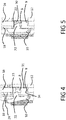
- Figure 5 shows the condition where tooth 9 has completely released seat 8 and is housed in slot 24 after occlusion mechanism 6 has rotated with respect to selectively disengageable unit 4.
- Head 22 is fully overlapped on seat 8 and, due to the biasing action of a spring 29, moves down and snaps into seat 8 to rest against sprocket 16 along the circumferential direction. Abutment of head 22 against sprocket 16 is kept by the action of spring 25 to define a retaining position of retainer 10.
- an extraction position of tooth 9 from seat 8 is kept while plunger 7 is outside seat 8.
- the operator can release handles 20 and retainer 10 keeps the angular position such that tooth 9 is out of seat 8.
- tooth 9 is circumferentially spaced from plunger 7 via a gap G (see figure 6 ).
- the operator shall switch the PTO off as soon as he or she understands that pick-up is disconnected from the PTO because the safety clutch 1 automatically switched in the disengaged position.
- safety clutch 1 comprises handles 20 according to figure 1
- disconnection of the PTO is the safest possible condition to guarantee that hands of the operator are not hurt when he or she grabs handles 20 and rotates disk 18 so that tooth 9 moves out from seat 8 and spring 25 is kept in a compressed state via arm 10 engaging seat 8.
- plunger 7 When clutch 1 is engaged and torque is transferred, plunger 7 is partly housed in sheath 14 and partly contacts a chamfered edge 30 of seat 8. The inclination of chamfered edge 30 is such to properly load plunger 7 to transmit torque until the maximum threshold is reached. When this happens, chamfered edge 30 applies on plunger 7 a load having a component that is parallel to the action of spring 13. The magnitude of such a component depends on the inclination of chamfered edge 30. If torque tends to further increase, the component parallel to axis A increases as well and this will cause compression of spring 13 to cause retraction of plunger 7 and disengagement of clutch 1. Therefore, preload of spring 13 sets the maximum level of torque transmitted by clutch 1.
- plunger 7 In case, by chance, plunger 7 is contacting tooth 9 and fully overlaps seat 8 when the operator has removed the blockage and decides to move occlusion mechanism 6, upon exit of tooth 9 from seat 8, plunger 7 would enter seat 8 and lift retainer 10 so that the latter is immediately disengaged from seat 8, as already mentioned in the above paragraphs.
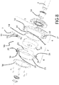
- FIG. 7 schematically shows a trailed baler 40 powered by the PTO of a tractor (not shown).
- Power from the PTO drives a gearbox (not shown) connected to a plurality of driven functional units, such as a compacting device preferably comprising belts 41, and a pick-up or feeder 42 comprising a plurality of tines 43 movable in a predetermined path to lift crop material from the ground and deliver it towards a compacting chamber 44 of baler 40.
- pick-up 42 is in series to compacting device with respect to the gearbox.
- torque transfer from PTO to functional units is provided with a speed reduction in order to increase torque available to the functional units.
- Safety clutch 1 can be placed in any position along the torque path on the baler, depending on the intended use.
- safety clutch 1 is in series between either the functional unit or the gearbox and pick-up 42.
- a clutch according to the present invention has the following advantages.
- clutch 50 is a further embodiment of a safety clutch according to the present invention. Elements and components of clutch 50 that are functionally identical to those already described in the preceding paragraphs will maintain the same reference numeral.
- Sprocket 16 of selectively disengageable unit 4 comprises a hub 52 radially supported by shaft 3 via a bushing 53.
- Seat 8 and slot 24 are radial and defined by a collar 54 rigidly connected to sprocket 16.
- sprocket 16 and collar 54 are a single body.
- Stop 27 radially projects from collar 54.
- Retainer 10 and spring 29 are attached to ring 55 as well so that head 22 reaches seat 8 through hole 23.
- the latter is radial and defined by ring 55.
- Ring 55 is axially attached to disengageable unit 4 via a flange 56 so that ring 55 is axially interposed between flange 56 and sprocket 16.
- flange 56 is attached to selectively disengageable unit 4, in particular to collar 54, via a plurality of screws.
- the operator may act on handles 20 or another manual grip or hold provided on obstruction mechanism 6.
- the operator may operate a servo-mechanism to rotate obstruction mechanism 6 with respect to selectively disengageable unit 4 to have tooth 9 exit, i.e. along the circumferential direction, from seat 8 and, thus, have clutch 1 re-engaged.
Description
- The present invention relates to a safety clutch for an agricultural vehicle or for a trailed accessory attached to an agricultural vehicle, in particular to power an implement.
- According to the present specification, an implement can be attached to the agricultural vehicle, e.g. a pick-up, or on a power accessory or machine trailed by a tractor and powered by the PTO of the tractor, e.g. a baler.
- Safety of an agricultural vehicle operator is a key issue. In particular, it is important to avoid that rotating shafts, that may be accessible by the operator in case of blockage by the crop or the like, may injure arms, legs or hands when the operator approaches the implement or the trailed machine to remove the cause of the blockage. A safety procedure prescribes that the driving shaft or the PTO shall be disconnected from the traction engine or the power hydraulic power source of the vehicle before the operator is able to approach the blocked implement or trailed machine.
- It is known to provide a torque limiter to automatically disconnect torque transmission from the driving shaft of an implement or of a trailed machine when the implement or accessory is blocked e.g. by crop and the operator is driving the vehicle. The torque limiter sets a maximum torque level to be transmitted to the implement or trailed accessory and this avoids that blockage may damage the vehicle or the trailed accessory or both.
- Sometimes the operator approaches a blocked implement or trailed machine to remove the cause of blockage, e.g. an obstruction, but the driving shaft of the implement or the PTO attached to the trailed accessory is still running.
- Known torque limiters are such that re-engagement is dependent on torque level, i.e. re-engagement occurs when the torque drops below the pre-defined maximum level. This is normally the case when the operator removes the obstruction and the PTO or the driving shaft are not switched off. Sudden re-engagement of the torque limiter may cause severe injuries to the operator if the latter removes the obstruction using his/her feet, hands, arms etc. because the implement or the trailed accessory will immediately start to work again as soon as the torque limiter is re-engaged.
- Even in case the PTO is disconnected or the driving shaft is not driven by the traction motor during removal of crop plug, power transmission via torque limiter may be inadvertently started too early. This may be a risk in case the operator is very close to the implement.
- In
FR 2 316 476 - In
US 2003/136625 a torque limiting coupling is shown having a coupling hub with circumferentially distributed apertures. A switching disk is rotatably arranged between a coupling position and an uncoupling position. The switching disk is loaded towards the coupling position and loads driving members towards the coupling hub. When a torque limit is exceeded, the driving members are transferred into the uncoupling position. A locking means is adjustable between a locking position, where the switching disk is locked in its uncoupling position, and a disengaging position. A retainer is adjustable between a retaining position, where the locking means is secured in its disengaging position, and a releasing position. A detent pawl is movable between a neutral position and a disconnecting position. In the disconnecting position, the detent pawl transfers the switching disk into the uncoupling position. In the disconnecting position, the detent pawl transfers the retainer into the retaining position. -
DE 44 41 218 - The scope of the present invention is to provide a safety clutch that solves the above mentioned problems.
- The scope of the present invention is achieved by a clutch that, once disconnected because of torque peak due to an obstruction, is re-engaged only upon a specific intentional operation from the operator.
- This is in particular achieved by a clutch according to
claim 1. - Other embodiments of the invention are described below and in the appended claims.
- For a better understanding of the present invention, the latter will further be disclosed with reference to the accompanying figures in which:
-
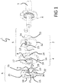
Figure 1 is an exploded view of a clutch according to the present invention; -
Figure 2 is a cross section offigure 1 in a plane offset from axis A offigure 1 ; -
Figure 3 is a cross section offigure 1 in the same plane as that offigure 2 ; -
Figures 4, 5 and6 are respective enlarged views of a detail offigure 1 ; -
Figure 7 is a schematic drawing of a conventional trailed baler comprising a safety clutch according to the present invention; -
Figure 8 is an exploded view of a clutch according to a second embodiment of the present invention; -
Figure 9 is a cross section view along an axial plane, of the embodiment according tofigure 8 ; and -
Figure 10 is a cross section according to plane X-X offigure 9 . -
Figure 1 refers, as a whole, to asafety clutch 1 comprising a rotatingunit 2 angularly connected to ashaft 3, and a selectivelydisengageable unit 4 coaxial to rotatingunit 2 and suitable for powering a device that may be blocked during use, e.g. by an obstruction of crop.Safety clutch 1 further comprises a zerobacklash torque limiter 5 operating to angularly connect rotatingunit 2 and selectivelydisengageable unit 4 for torque transfer and operation of an agricultural implement or trailed agricultural accessory until a maximum torque level is reached.Safety clutch 1 also comprises asafety occlusion mechanism 6 interacting withtorque limiter 5 to maintain angular disengagement of rotatingunit 2 from selectivelydisengageable unit 4 as soon as the maximum torque level is exceeded in use. - In particular,
torque limiter 5 comprises abiased plunger 7 releasably coupled in aseat 8 to provide a shape coupling for torque transferring between rotatingunit 2 and selectivelydisengageable unit 4 in normal use ofclutch 1.Occlusion mechanism 6 comprises an obstructingelement 9 movable between an obstructing position whereseat 8 is engaged by obstructingelement 9 and a release position whereseat 8 is engaged byplunger 7 for torque transfer. In particular, whenocclusion mechanism 6 is in the obstruction position, selectivelydisengageable unit 4 is blocked by the crop plug whilst rotatingunit 2 may still rotate. In such a condition,plunger 7 cannot enterseat 8. In particular, rotatingunit 2 and selectivelydisengageable unit 4 relatively rotate in both directions whenocclusion mechanism 6 is in the obstruction position. - In order to have the clutch re-engaged, the operator shall act so as to bring obstructing
element 9 in the release position. Then, when torque is applied toclutch 1,plunger 7 will find anun-obstructed seat 8, will be biased to enterseat 8 and this will re-instate torque transfer throughclutch 1. - According to a preferred embodiment,
safety occlusion mechanism 6 is biased to reach and maintain obstructing position. Therefore, as soon as maximum torque level is exceeded, plunger 7 retracts and angularly moves out ofseat 8 and the latter is engaged by obstructingelement 9. - Furthermore,
safety occlusion mechanism 6 comprises areleasable retainer 10 to keep release position after the operator has acted to remove obstructingelement 9 fromseat 8 and untilplunger 7 reaches the seat itself via relative rotation of rotatingunit 2 and selectivelydisengageable unit 4. - In order to provide an automatic engagement of
plunger 7 inseat 8 whenretainer 10 holds the release position of obstructingelement 9, the load acting onbiased plunger 7 when the latter entersseat 8 is such to disengagereleasable retainer 10. According to a preferred embodiment,retainer 10 is biased to enter inseat 8 when keeping the release position of thesafety occlusion mechanism 6; and plunger 7, upon enteringseat 8 during re-engagement, pushesretainer 10 out ofseat 8. - According to the preferred embodiment of
figure 1 , rotatingunit 2 comprises ahub 11 connectable toshaft 3 and aflange 12 radially projecting fromhub 11. Preferablyhub 11 is keyed toshaft 3 but other angularly rigid connections are possible depending on use. -
Clutch 1 is also designed so thatplunger 7 is driven in rotation by rotatingunit 2.Seat 8 forms part of the selectivelydisengageable unit 4. Preferably,plunger 7 moves to engageseat 8 along a direction substantially parallel to an axis A ofrotating unit 2 and is biased by acoil spring 13.Coil spring 13 is housed in asheath 14 projecting axially fromflange 12 and offset fromhub 11. Depending on the case,sheath 14 may be skew with respect tohub 11 or parallel tohub 11, the latter layout being shown infigure 1 .Sheath 14 houses apad 15 axially interposed betweenplunger 7 andcoil spring 13.Sheath 14 guides the axial movement ofplunger 7, which is preferably spherical, andpad 15. - Selectively
disengageable unit 4 comprises asprocket 16 connectable to a chain for torque transmission to e.g. a pick-up device of a baler, and is radially supported onshaft 3 by ajournal bearing 17. Depending on the use ofclutch 1,sprocket 16 may be substituted by a pulley, a gear or another torque-transmitting element and/or journal bearing may be substituted by a rolling bearing. - According to the embodiment of
figure 1 ,safety obstruction mechanism 6 comprises arotating disk 18 radially supported on acollar 19 ofsprocket 16, and one ormore handles 20 to help rotation ofdisk 18 by the operator. Obstructingelement 9 is a tooth axially projecting fromdisk 18 on an opposite side ofhandles 20 andretainer 10 comprises a pivotingarm 21 hinged ondisk 18. In particular,arm 21 comprises a head 22 (figure 2 ) movable inside ahole 23 ofdisk 18 so as to be adjacent totooth 9 along a circumferential direction. Furthermore,tooth 9 is housed in aslot 24, preferably an arched slot, branching fromseat 8 so that, whendisk 18 rotates relatively to sprocket 16,tooth 9 moves away or towardsseat 8. -
Safety occlusion mechanism 6 further comprises aspring 25, preferably a coil spring, to angularlybias disk 18 in the direction so thattooth 9 is kept insideseat 8, i.e. the obstructing positon ofocclusion mechanism 6. According to a preferred embodiment,spring 25 is compressed between astop 26 ofdisk 18 and astop 27 ofsprocket 16. -
Figure 2 shows the engagement position ofclutch 1. In particular,plunger 7 is shape-coupled inseat 8 and torque is transferred throughplunger 7, in particular producing shear forces inplunger 7.Tooth 9 do not engageseat 8 and the action ofspring 13 onplunger 7 is such to keephead 22 lifted so that there is no compression ofspring 25 by means ofretainer 10. Furthermore, action ofspring 13 is such to counterbalance the load ofspring 25 so as to keeptooth 9 outsideseat 8 when, during engagement ofclutch 1,plunger 7 is housed inseat 8. The engagement position according tofigure 2 is such that proper torque levels are transferred during use ofclutch 1 androtating unit 2 is rotatingly coupled to selectivelydisengageable unit 4. -
Figure 3 shows a disengaged position ofclutch 1. With respect tofigure 2 ,plunger 7 is retracted fromseat 8 against the action ofspring 13;disk 18 is angularly rotated in the circumferential direction by means ofspring 25 so thattooth 9 obstructsseat 8 and hinders re-entrance ofplunger 7; andhead 22 is more lifted and biased against a face orsurface 28 ofsprocket 16 opposed torotating unit 2. In the disengaged position, the operator may safely act to remove the crop plug from e.g. the pick-up of a baler, because the pick-up, which is connected to sprocket 16 by a chain, is not powered anymore. Furthermore, the operator can grab and rotate the pick-up to help remove the plug. In case, e.g. after action of the operator on the pick-up,plunger 7 facesseat 8,tooth 9 obstructs coupling of the plunger insideseat 8 so thatrotating unit 2 and selectivelydisengageable unit 4 can freely rotate in both directions one with respect to the other. In particular,tooth 9 is guided bydisk 18 to move along a trajectory that is transversal, preferably perpendicular, to the action ofspring 13 onplunger 7. According to the embodiment of thefigures 1 to 6 , guiding oftooth 9 along its trajectory is provided by the rotating coupling betweendisk 18 andsprocket 16. This may be obtained, depending on the design working conditions, by a rolling bearing or by a friction bushing or journal bearing. -
Figures 4 and 5 show a sequence of phases to bring again clutch 1 from the disengaged position offigure 3 to the engaged position offigure 2 . - In particular,
figure 4 shows the consequence of an incipient rotation ofdisk 18 by the operator when holding handles 20 to intentionally movetooth 9 out ofseat 8 against the action ofspring 25. Gradually,tooth 9 moves back insideslot 24 andhead 22 fully overlapsseat 8 sliding onface 28. -
Figure 5 shows the condition wheretooth 9 has completely releasedseat 8 and is housed inslot 24 afterocclusion mechanism 6 has rotated with respect to selectivelydisengageable unit 4.Head 22 is fully overlapped onseat 8 and, due to the biasing action of aspring 29, moves down and snaps intoseat 8 to rest againstsprocket 16 along the circumferential direction. Abutment ofhead 22 againstsprocket 16 is kept by the action ofspring 25 to define a retaining position ofretainer 10. In such a condition, an extraction position oftooth 9 fromseat 8 is kept whileplunger 7 is outsideseat 8. Furthermore, in such a condition, the operator can release handles 20 andretainer 10 keeps the angular position such thattooth 9 is out ofseat 8. In the retaining position,tooth 9 is circumferentially spaced fromplunger 7 via a gap G (seefigure 6 ). - According to a preferred safety procedure, the operator shall switch the PTO off as soon as he or she understands that pick-up is disconnected from the PTO because the
safety clutch 1 automatically switched in the disengaged position. Whensafety clutch 1 compriseshandles 20 according tofigure 1 , disconnection of the PTO is the safest possible condition to guarantee that hands of the operator are not hurt when he or she grabs handles 20 and rotatesdisk 18 so thattooth 9 moves out fromseat 8 andspring 25 is kept in a compressed state viaarm 10engaging seat 8. - As soon as
plunger 7 rotates with respect tosprocket 16 whileretainer 10 is engaged, e.g. because the operator has powered againshaft 3 by means of the PTO,seat 8 will at one point again fully overlapplunger 7. In such an instance,plunger 7contacts head 22 and action ofspring 13 overcomes the action ofspring 29. This liftshead 22 out of abutment againstsprocket 16. As soon ashead 22 is out of abutment againstseat 8 along the circumferential direction,tooth 9 will close gap G by means ofspring 25 andhead 22 is circumferentially displaced out ofseat 8. In particular,head 22 moves away fromslot 24 whenspring 25 closes gap G. As shown infigure 2 , in the engaged position ofclutch 1,head 22 is prevented from snapping intoseat 8 when the maximum torque limit is reached andplunger 7 retracts away fromseat 8 to disengageclutch 1. This is because, in such a condition,head 22 andseat 8 are misaligned. Furthermore, the action ofspring 13 is such to couple againplunger 7 inseat 8 against the action ofspring 29. It is important to note that, albeit rotatingelement 2 and selectivelydisengageable unit 4 relatively rotate in both directions of rotation when clutch 1 is disengaged, rotation for torque transmission in use is always in a single direction of rotation. To this regard,tooth 9 entersseat 8 along the single direction of rotation and gap G is closed after a rotation in such single direction. - Preferably, during closure of gap G,
head 22 lifts in such a way that head 22 is misaligned withseat 8. By means of an inclined surface a first portion ofhead 22 still facesseat 8 and a second portion ofhead 22 facessurface 28. According to the embodiment of thefigures 1 to 6 ,head 22 is inclined. According to a non-illustrated alternative, face 28 comprises a ramp on whichhead 22 slides to progressively lift out ofseat 8 whenretainer 10 moves away fromslot 24. In the engaged position ofclutch 1,head 22 may either contact an edge ofseat 8 or be lifted from such an edge because of contact withplunger 7. - When clutch 1 is engaged and torque is transferred,
plunger 7 is partly housed insheath 14 and partly contacts a chamferededge 30 ofseat 8. The inclination ofchamfered edge 30 is such to properly loadplunger 7 to transmit torque until the maximum threshold is reached. When this happens, chamferededge 30 applies on plunger 7 a load having a component that is parallel to the action ofspring 13. The magnitude of such a component depends on the inclination ofchamfered edge 30. If torque tends to further increase, the component parallel to axis A increases as well and this will cause compression ofspring 13 to cause retraction ofplunger 7 and disengagement ofclutch 1. Therefore, preload ofspring 13 sets the maximum level of torque transmitted byclutch 1. - In case, by chance,
plunger 7 is contactingtooth 9 and fully overlapsseat 8 when the operator has removed the blockage and decides to moveocclusion mechanism 6, upon exit oftooth 9 fromseat 8,plunger 7 would enterseat 8 and liftretainer 10 so that the latter is immediately disengaged fromseat 8, as already mentioned in the above paragraphs. - When clutch 1 disengages after the maximum torque level is reached, torque transmitted even in case of continuing rotation of
rotating element 2 is negligible and can be reduced to friction torque of rotatingelement 2 sliding against selectivelydisengageable unit 4. Furthermore, in view of interference caused by circumferential misalignment ofhead 22 andseat 8 in the engaged position ofclutch 1, whenplunger 7 retracts andtooth 9 rotates in the single direction intoseat 8,head 22 is prevented from snapping intoseat 8 and slides away fromseat 8 onface 28 along the circumferential direction. - In the disengaged position of
clutch 1, ideally there is no torque transmitted even incase rotating element 2 still rotates, except for the very low torque due to friction. This is obtained in particular iftooth 9 is shaped to contactplunger 7 during rotation ofrotating element 2 and supportsplunger 7 so thatspring 13 does not substantially extend or compress during a complete route ofrotating element 2. According to the embodiment offigures 1 to 6 ,plunger 7 rolls on a substantially flat face ofsprocket 16 and ahead 31 oftooth 9 is substantially coplanar with such a face. Furthermore, according to the embodiment of the figures,slot 24 andhead 31 have a radial position to overlap a rolling path ofplunger 7 onsprocket 16. Preferably, also radial width ofslot 24 is such that, whenplunger 7 rolls onslot 24,spring 13 does not substantially extend or compress. -
Figure 7 schematically shows a trailedbaler 40 powered by the PTO of a tractor (not shown). Power from the PTO drives a gearbox (not shown) connected to a plurality of driven functional units, such as a compacting device preferably comprisingbelts 41, and a pick-up orfeeder 42 comprising a plurality oftines 43 movable in a predetermined path to lift crop material from the ground and deliver it towards a compactingchamber 44 ofbaler 40. Preferably pick-up 42 is in series to compacting device with respect to the gearbox. In particular, torque transfer from PTO to functional units is provided with a speed reduction in order to increase torque available to the functional units.Safety clutch 1 can be placed in any position along the torque path on the baler, depending on the intended use. Preferably,safety clutch 1 is in series between either the functional unit or the gearbox and pick-up 42. - The above applies as well to implements on board of an agricultural vehicle, including the PTO.
- A clutch according to the present invention has the following advantages.
-
Clutch 1 is re-engaged only when the operator intentionally acts onocclusion mechanism 6 to removetooth 9 fromseat 8. Even in case the driving shaft or the PTO are still running, there is no automatic re-engagement ofclutch 1 upon removal of the blockage. According to a preferred safety procedure, the PTO needs to be stopped completely before the operator will be able to reposition theocclusion mechanism 6 viahandles 20 to make re-engagement of the clutch 1 possible. - Furthermore, gap G ensures that, after release of the retaining position of
head 22,clutch 1 re-engages and is fully reset in order to disengage in case of e.g. obstruction of the pick-up by a plug of crop. -
Plunger 7 stopstooth 9 andsafety occlusion mechanism 6 is biased in order to swiftly pushtooth 9 intoseat 8 whenplunger 7 retracts after the maximum torque level is reached. This is an embodiment of a zero-backlash torque limiter and ensures prompt disengagement ofclutch 1. - Furthermore, other features of dependent claims are such to provide a simple and compact structure, which ensures functioning in the harsh conditions of agricultural vehicles.
- It is clear furthermore that changes and variations are applicable to the clutch according to the present invention without departing from the scope of protection as defined in the attached claims.
- Depending on the torque transmitted, it is possible to apply zero-
backlash torque limiter 5 to function along a radial direction instead of the axial direction disclosed in the attached drawings. - According to
figures 8-10 , clutch 50 is a further embodiment of a safety clutch according to the present invention. Elements and components of clutch 50 that are functionally identical to those already described in the preceding paragraphs will maintain the same reference numeral. -
Clutch 50 is configured to provide a radial layout of zero-backlash torque limiter 5, compared to the axial layout ofsafety clutch 1. In particular, rotatingunit 2 comprises ahousing 51 rotationally fixed toshaft 3. Preferably,housing 51 is a disk and housesspring 13,pad 15 andplunger 7. Furthermore,housing 51 defines a radial guide forplunger 7. -
Sprocket 16 of selectivelydisengageable unit 4 comprises ahub 52 radially supported byshaft 3 via abushing 53. -
Seat 8 andslot 24 are radial and defined by acollar 54 rigidly connected tosprocket 16. Preferablysprocket 16 andcollar 54 are a single body.Stop 27 radially projects fromcollar 54. -
Safety obstruction mechanism 6 comprises aring 55 radially supported bycollar 54.Handles 20 project radially fromring 55 as well as stop 26 to press onspring 25. -
Retainer 10 andspring 29 are attached to ring 55 as well so thathead 22 reachesseat 8 throughhole 23. The latter is radial and defined byring 55. -
Ring 55 is axially attached todisengageable unit 4 via aflange 56 so thatring 55 is axially interposed betweenflange 56 andsprocket 16. Preferably,flange 56 is attached to selectivelydisengageable unit 4, in particular tocollar 54, via a plurality of screws. - The operator may act on
handles 20 or another manual grip or hold provided onobstruction mechanism 6. As an alternative, the operator may operate a servo-mechanism to rotateobstruction mechanism 6 with respect to selectivelydisengageable unit 4 to havetooth 9 exit, i.e. along the circumferential direction, fromseat 8 and, thus, have clutch 1 re-engaged.
Claims (20)
- A clutch (1) for an agricultural implement comprising:- a rotating unit (2) for connection to a powered shaft (3),- a selectively disengageable unit (4) coaxial to the rotating unit (2) to transfer a power torque within the implement,- a zero-backlash torque limiter (5) operable in:* an engaged position where a biased plunger (7) is housed in a seat (8) to angularly connect rotating unit (2) and selectively disengageable unit (4) for torque transfer until a maximum torque level is reached; and* a disengaged position where the plunger (7) is retracted outside the seat (8); and- a safety occlusion mechanism (6) having an obstructing element (9) selectively movable in an obstructing position to hinder the seat (8) to house plunger (7) and in a release position to allow shape coupling when the plunger (7) and the seat (8) overlap, wherein the occlusion mechanism (6) is biased to switch in the obstruction position when the plunger (7) exits the seat (8) to reach the disengaged position when the maximum torque level is reached, and is operable against the bias by an operator to switch back into the release position; characterised in that the clutch (1) further comprises a biased retainer (10), wherein the biased retainer (10) snaps in a retaining position to maintain a predefined extraction position of the obstructing element (9) from the seat (8) when occlusion mechanism (6) is operated against the bias and the plunger (7) is outside the seat (8).
- Clutch according to claim 1, wherein the retainer (10) is released from the retaining position by the biased plunger (7) when entering in the seat (8) and, after release of the retaining position, the retainer (10) is rotated by the bias of the occlusion mechanism (6) to abut by overlap on a surface (28) outside of the seat (8).
- Clutch according to claim 2, wherein, in the engaged position, the plunger (7) stops the obstructing element (9) to enter the seat (8) against the action of the biased occlusion mechanism (6).
- Clutch according to claim 3, wherein the seat (8) is through to selectively engage the plunger (7) or retainer (10) and wherein the plunger (7) is opposite to the retainer (10) with respect to the seat (8).
- Clutch according to any of claims 1 to 4, wherein the occlusion mechanism (6) relatively rotates with respect to the selectively disengageable unit (4) and comprises the retainer (10).
- Clutch according to any of the preceding claims, wherein upon relative rotation of the rotating unit (2) and the selectively disengageable unit (4) in the disengaged position, the plunger (7) rolls on a surface such that compression and elongation of the biased plunger (7) are substantially null.
- Clutch according to any of the preceding claims, wherein the obstructing element (9) is such to enter the seat (8) along a direction perpendicular to the action of the biased plunger (7) when entering the seat (8).
- Clutch according to any of the preceding claims, wherein the plunger (7) is a roller.
- Clutch according to claim 8, wherein the obstructing element (9) is a tooth overlapping a rolling path of the plunger (7) in the disengaged position.
- Clutch according to any of the preceding claims, wherein the occlusion mechanism (6) comprises a handle (20) or a manual grip to extract obstructing element (9) from the seat (8).
- Clutch according to any of the preceding claims, wherein the plunger (7) moves along a substantially axial direction to engage / disengage the seat (8).
- Clutch according to claim 11, wherein the plunger (7) is offset with respect to an axis of revolution (A) of the rotating unit (2).
- Clutch according to one of claims 11 or 12, wherein the obstructing element (9) is housed in an arched slot (24).
- Clutch according to any of claims 11 to 13, wherein the plunger (7) contacts a substantially flat face of the selectively disengageable unit (4) or a head (31) of the obstructing element (9) when the obstructing element (9) is in the obstructing position.
- Clutch according to any of claims 1 to 10, wherein the plunger (7) moves along a substantially radial direction to engage / disengage the seat (8).
- Clutch according to claim 15, wherein the plunger (7) is housed in a disk (51) of the rotating unit (2).
- Clutch according to one of claims 15 or 16, wherein the obstructing element (9) is housed in a radial slot (24).
- Clutch according to any of claims 15 to 17, wherein the plunger (7) contacts a collar (54) of the selectively disengageable unit (4) or a head (31) of the obstructing element (9) when the obstructing element (9) is in the obstructing position.
- Agricultural vehicle or trailed agricultural accessory (40) comprising an implement (42) driven via a safety clutch (1) according to any of the preceding claims.
- Method of operation of a clutch according to any of the claims 1 to 18, comprising the step of operating the safety occlusion mechanism (8) to switch back into the release position.
Applications Claiming Priority (1)
| Application Number | Priority Date | Filing Date | Title |
|---|---|---|---|
| BE2016/5746A BE1024270B1 (en) | 2016-10-06 | 2016-10-06 | SAFETY COUPLING FOR AN AGRICULTURAL VEHICLE OR ITS TRAILED ACCESSORIES |
Publications (2)
| Publication Number | Publication Date |
|---|---|
| EP3321533A1 EP3321533A1 (en) | 2018-05-16 |
| EP3321533B1 true EP3321533B1 (en) | 2019-06-19 |
Family
ID=57838073
Family Applications (1)
| Application Number | Title | Priority Date | Filing Date |
|---|---|---|---|
| EP17193576.0A Active EP3321533B1 (en) | 2016-10-06 | 2017-09-27 | Safety clutch for an agricultural vehicle or trailed accessory thereof |
Country Status (3)
| Country | Link |
|---|---|
| US (1) | US10455754B2 (en) |
| EP (1) | EP3321533B1 (en) |
| BE (1) | BE1024270B1 (en) |
Family Cites Families (15)
| Publication number | Priority date | Publication date | Assignee | Title |
|---|---|---|---|---|
| DE441218C (en) | 1927-02-28 | Alfred Rubart | Rock dust spreader | |
| US998615A (en) * | 1907-12-02 | 1911-07-25 | Cox Multi Mailer Company | Clutch. |
| US3132730A (en) * | 1960-08-31 | 1964-05-12 | Josef Y Dahlstrand | Torque disconnect safety coupling |
| GB1160062A (en) * | 1966-01-11 | 1969-07-30 | Fisholow Prod Ltd | Improvements in or relating to Overload Clutches |
| FR2316476A1 (en) * | 1975-06-30 | 1977-01-28 | Duc Henri | Automatically declutchable drive coupling - has inserts on driven member engaging ramp surfaces on drive member |
| IT1070120B (en) * | 1975-09-11 | 1985-03-25 | Walterscheid Gmbh Jean | FREEWHEEL COUPLING FOR THE LIMITATION OF THE TORQUE TRANSMITTED BY A MOTOR TO AN OPERATING MACHINE |
| GB1548751A (en) * | 1976-03-17 | 1979-07-18 | Brown Sadi Sa David | Torque-limiting devices |
| US4220230A (en) * | 1979-03-30 | 1980-09-02 | Hansen Quinten A | Overload release clutch |
| DE3602282A1 (en) * | 1986-01-25 | 1987-08-20 | Ringspann Maurer Kg A | OVERLOAD CLUTCH |
| DE4441218C2 (en) * | 1994-11-19 | 1998-07-09 | Walterscheid Gmbh Gkn | Torque limiting clutch or freewheel |
| DE19611622C1 (en) | 1996-03-25 | 1997-07-24 | Walterscheid Gmbh Gkn | Torque limiter clutch for agricultural vehicles |
| DE10145430C2 (en) | 2001-09-14 | 2003-09-25 | Walterscheid Gmbh Gkn | Torque limiting clutch |
| DE10201988C2 (en) * | 2002-01-21 | 2003-12-24 | Walterscheid Gmbh Gkn | Torque limiting clutch |
| DE102007057865A1 (en) | 2007-11-29 | 2009-06-04 | Gkn Walterscheid Gmbh | Torque limiting clutch |
| DE102009037026B4 (en) * | 2009-08-13 | 2011-07-28 | GKN Walterscheid GmbH, 53797 | Torque limiting clutch |
-
2016
- 2016-10-06 BE BE2016/5746A patent/BE1024270B1/en active IP Right Grant
-
2017
- 2017-09-27 EP EP17193576.0A patent/EP3321533B1/en active Active
- 2017-10-06 US US15/727,294 patent/US10455754B2/en active Active
Non-Patent Citations (1)
| Title |
|---|
| None * |
Also Published As
| Publication number | Publication date |
|---|---|
| US20180098480A1 (en) | 2018-04-12 |
| US10455754B2 (en) | 2019-10-29 |
| EP3321533A1 (en) | 2018-05-16 |
| BE1024270B1 (en) | 2018-01-10 |
Similar Documents
| Publication | Publication Date | Title |
|---|---|---|
| CA1125198A (en) | Overload clutch | |
| EP3343056A1 (en) | Electric pushing rod | |
| EP2571345B1 (en) | Combines | |
| US4071105A (en) | Coupling device for a power transmission shaft | |
| CN104675875A (en) | Torque limiter | |
| US20120129637A1 (en) | Transmission device for self-propelled equipment and self-propelled equipment fitted with such a transmission | |
| EP3321533B1 (en) | Safety clutch for an agricultural vehicle or trailed accessory thereof | |
| CA2358817C (en) | Detent torque overload clutch | |
| EP3423334B1 (en) | Walk behind power equipment with tight turning capability | |
| EP0952027B1 (en) | Auxiliary drive for utility vehicle and method of operation thereof | |
| GB2060339A (en) | Overload clutches | |
| KR102341958B1 (en) | Torque limiter with overspeed protection | |
| US6749049B2 (en) | Torque limiting coupling | |
| EP2693069B1 (en) | Friction drive clutch having ramped members | |
| JPS5834092B2 (en) | Douriyoku Karitoriki | |
| GB2042655A (en) | Torque Limiting Clutch | |
| EP4167709B1 (en) | A protection system for a drive shaft and drive shaft comprising said protection system | |
| DE102009015822B3 (en) | Hedge trimmer, has clutch element axially movable against force of spring that is supported against front surface of clutch element, where clutch claws are not provided in contact in hinged position | |
| EP2168426A1 (en) | Agricultural machine | |
| CN107448491B (en) | Automatic disengaging type coupling for rolling-in foreign matter | |
| GB2403517A (en) | A switchable freewheel coupling | |
| CZ20012679A3 (en) | Tractor for mowing grass | |
| CS236607B1 (en) | Safety claw clutch with adjustable moment | |
| JPS5823251B2 (en) | This is the first time I've ever seen such a thing. |
Legal Events
| Date | Code | Title | Description |
|---|---|---|---|
| PUAI | Public reference made under article 153(3) epc to a published international application that has entered the european phase |
Free format text: ORIGINAL CODE: 0009012 |
|
| STAA | Information on the status of an ep patent application or granted ep patent |
Free format text: STATUS: THE APPLICATION HAS BEEN PUBLISHED |
|
| AK | Designated contracting states |
Kind code of ref document: A1 Designated state(s): AL AT BE BG CH CY CZ DE DK EE ES FI FR GB GR HR HU IE IS IT LI LT LU LV MC MK MT NL NO PL PT RO RS SE SI SK SM TR |
|
| AX | Request for extension of the european patent |
Extension state: BA ME |
|
| STAA | Information on the status of an ep patent application or granted ep patent |
Free format text: STATUS: REQUEST FOR EXAMINATION WAS MADE |
|
| 17P | Request for examination filed |
Effective date: 20181116 |
|
| RBV | Designated contracting states (corrected) |
Designated state(s): AL AT BE BG CH CY CZ DE DK EE ES FI FR GB GR HR HU IE IS IT LI LT LU LV MC MK MT NL NO PL PT RO RS SE SI SK SM TR |
|
| GRAP | Despatch of communication of intention to grant a patent |
Free format text: ORIGINAL CODE: EPIDOSNIGR1 |
|
| STAA | Information on the status of an ep patent application or granted ep patent |
Free format text: STATUS: GRANT OF PATENT IS INTENDED |
|
| RIC1 | Information provided on ipc code assigned before grant |
Ipc: F16D 43/206 20060101ALI20181203BHEP Ipc: F16D 7/08 20060101AFI20181203BHEP Ipc: A01F 15/08 20060101ALI20181203BHEP Ipc: F16D 43/208 20060101ALI20181203BHEP Ipc: F16D 7/10 20060101ALI20181203BHEP |
|
| INTG | Intention to grant announced |
Effective date: 20190108 |
|
| GRAS | Grant fee paid |
Free format text: ORIGINAL CODE: EPIDOSNIGR3 |
|
| GRAA | (expected) grant |
Free format text: ORIGINAL CODE: 0009210 |
|
| STAA | Information on the status of an ep patent application or granted ep patent |
Free format text: STATUS: THE PATENT HAS BEEN GRANTED |
|
| AK | Designated contracting states |
Kind code of ref document: B1 Designated state(s): AL AT BE BG CH CY CZ DE DK EE ES FI FR GB GR HR HU IE IS IT LI LT LU LV MC MK MT NL NO PL PT RO RS SE SI SK SM TR |
|
| REG | Reference to a national code |
Ref country code: GB Ref legal event code: FG4D |
|
| REG | Reference to a national code |
Ref country code: CH Ref legal event code: EP |
|
| REG | Reference to a national code |
Ref country code: IE Ref legal event code: FG4D |
|
| REG | Reference to a national code |
Ref country code: DE Ref legal event code: R096 Ref document number: 602017004636 Country of ref document: DE |
|
| REG | Reference to a national code |
Ref country code: AT Ref legal event code: REF Ref document number: 1145900 Country of ref document: AT Kind code of ref document: T Effective date: 20190715 |
|
| REG | Reference to a national code |
Ref country code: NL Ref legal event code: MP Effective date: 20190619 |
|
| PG25 | Lapsed in a contracting state [announced via postgrant information from national office to epo] |
Ref country code: HR Free format text: LAPSE BECAUSE OF FAILURE TO SUBMIT A TRANSLATION OF THE DESCRIPTION OR TO PAY THE FEE WITHIN THE PRESCRIBED TIME-LIMIT Effective date: 20190619 Ref country code: LT Free format text: LAPSE BECAUSE OF FAILURE TO SUBMIT A TRANSLATION OF THE DESCRIPTION OR TO PAY THE FEE WITHIN THE PRESCRIBED TIME-LIMIT Effective date: 20190619 Ref country code: FI Free format text: LAPSE BECAUSE OF FAILURE TO SUBMIT A TRANSLATION OF THE DESCRIPTION OR TO PAY THE FEE WITHIN THE PRESCRIBED TIME-LIMIT Effective date: 20190619 Ref country code: NO Free format text: LAPSE BECAUSE OF FAILURE TO SUBMIT A TRANSLATION OF THE DESCRIPTION OR TO PAY THE FEE WITHIN THE PRESCRIBED TIME-LIMIT Effective date: 20190919 Ref country code: SE Free format text: LAPSE BECAUSE OF FAILURE TO SUBMIT A TRANSLATION OF THE DESCRIPTION OR TO PAY THE FEE WITHIN THE PRESCRIBED TIME-LIMIT Effective date: 20190619 Ref country code: AL Free format text: LAPSE BECAUSE OF FAILURE TO SUBMIT A TRANSLATION OF THE DESCRIPTION OR TO PAY THE FEE WITHIN THE PRESCRIBED TIME-LIMIT Effective date: 20190619 |
|
| REG | Reference to a national code |
Ref country code: LT Ref legal event code: MG4D |
|
| PG25 | Lapsed in a contracting state [announced via postgrant information from national office to epo] |
Ref country code: LV Free format text: LAPSE BECAUSE OF FAILURE TO SUBMIT A TRANSLATION OF THE DESCRIPTION OR TO PAY THE FEE WITHIN THE PRESCRIBED TIME-LIMIT Effective date: 20190619 Ref country code: BG Free format text: LAPSE BECAUSE OF FAILURE TO SUBMIT A TRANSLATION OF THE DESCRIPTION OR TO PAY THE FEE WITHIN THE PRESCRIBED TIME-LIMIT Effective date: 20190919 Ref country code: RS Free format text: LAPSE BECAUSE OF FAILURE TO SUBMIT A TRANSLATION OF THE DESCRIPTION OR TO PAY THE FEE WITHIN THE PRESCRIBED TIME-LIMIT Effective date: 20190619 Ref country code: GR Free format text: LAPSE BECAUSE OF FAILURE TO SUBMIT A TRANSLATION OF THE DESCRIPTION OR TO PAY THE FEE WITHIN THE PRESCRIBED TIME-LIMIT Effective date: 20190920 |
|
| REG | Reference to a national code |
Ref country code: AT Ref legal event code: MK05 Ref document number: 1145900 Country of ref document: AT Kind code of ref document: T Effective date: 20190619 |
|
| PG25 | Lapsed in a contracting state [announced via postgrant information from national office to epo] |
Ref country code: RO Free format text: LAPSE BECAUSE OF FAILURE TO SUBMIT A TRANSLATION OF THE DESCRIPTION OR TO PAY THE FEE WITHIN THE PRESCRIBED TIME-LIMIT Effective date: 20190619 Ref country code: NL Free format text: LAPSE BECAUSE OF FAILURE TO SUBMIT A TRANSLATION OF THE DESCRIPTION OR TO PAY THE FEE WITHIN THE PRESCRIBED TIME-LIMIT Effective date: 20190619 Ref country code: CZ Free format text: LAPSE BECAUSE OF FAILURE TO SUBMIT A TRANSLATION OF THE DESCRIPTION OR TO PAY THE FEE WITHIN THE PRESCRIBED TIME-LIMIT Effective date: 20190619 Ref country code: PT Free format text: LAPSE BECAUSE OF FAILURE TO SUBMIT A TRANSLATION OF THE DESCRIPTION OR TO PAY THE FEE WITHIN THE PRESCRIBED TIME-LIMIT Effective date: 20191021 Ref country code: EE Free format text: LAPSE BECAUSE OF FAILURE TO SUBMIT A TRANSLATION OF THE DESCRIPTION OR TO PAY THE FEE WITHIN THE PRESCRIBED TIME-LIMIT Effective date: 20190619 Ref country code: SK Free format text: LAPSE BECAUSE OF FAILURE TO SUBMIT A TRANSLATION OF THE DESCRIPTION OR TO PAY THE FEE WITHIN THE PRESCRIBED TIME-LIMIT Effective date: 20190619 Ref country code: AT Free format text: LAPSE BECAUSE OF FAILURE TO SUBMIT A TRANSLATION OF THE DESCRIPTION OR TO PAY THE FEE WITHIN THE PRESCRIBED TIME-LIMIT Effective date: 20190619 |
|
| PG25 | Lapsed in a contracting state [announced via postgrant information from national office to epo] |
Ref country code: ES Free format text: LAPSE BECAUSE OF FAILURE TO SUBMIT A TRANSLATION OF THE DESCRIPTION OR TO PAY THE FEE WITHIN THE PRESCRIBED TIME-LIMIT Effective date: 20190619 Ref country code: IS Free format text: LAPSE BECAUSE OF FAILURE TO SUBMIT A TRANSLATION OF THE DESCRIPTION OR TO PAY THE FEE WITHIN THE PRESCRIBED TIME-LIMIT Effective date: 20191019 Ref country code: SM Free format text: LAPSE BECAUSE OF FAILURE TO SUBMIT A TRANSLATION OF THE DESCRIPTION OR TO PAY THE FEE WITHIN THE PRESCRIBED TIME-LIMIT Effective date: 20190619 |
|
| PG25 | Lapsed in a contracting state [announced via postgrant information from national office to epo] |
Ref country code: TR Free format text: LAPSE BECAUSE OF FAILURE TO SUBMIT A TRANSLATION OF THE DESCRIPTION OR TO PAY THE FEE WITHIN THE PRESCRIBED TIME-LIMIT Effective date: 20190619 |
|
| PG25 | Lapsed in a contracting state [announced via postgrant information from national office to epo] |
Ref country code: DK Free format text: LAPSE BECAUSE OF FAILURE TO SUBMIT A TRANSLATION OF THE DESCRIPTION OR TO PAY THE FEE WITHIN THE PRESCRIBED TIME-LIMIT Effective date: 20190619 Ref country code: PL Free format text: LAPSE BECAUSE OF FAILURE TO SUBMIT A TRANSLATION OF THE DESCRIPTION OR TO PAY THE FEE WITHIN THE PRESCRIBED TIME-LIMIT Effective date: 20190619 |
|
| PG25 | Lapsed in a contracting state [announced via postgrant information from national office to epo] |
Ref country code: MC Free format text: LAPSE BECAUSE OF FAILURE TO SUBMIT A TRANSLATION OF THE DESCRIPTION OR TO PAY THE FEE WITHIN THE PRESCRIBED TIME-LIMIT Effective date: 20190619 Ref country code: IS Free format text: LAPSE BECAUSE OF FAILURE TO SUBMIT A TRANSLATION OF THE DESCRIPTION OR TO PAY THE FEE WITHIN THE PRESCRIBED TIME-LIMIT Effective date: 20200224 |
|
| REG | Reference to a national code |
Ref country code: DE Ref legal event code: R097 Ref document number: 602017004636 Country of ref document: DE |
|
| PLBE | No opposition filed within time limit |
Free format text: ORIGINAL CODE: 0009261 |
|
| STAA | Information on the status of an ep patent application or granted ep patent |
Free format text: STATUS: NO OPPOSITION FILED WITHIN TIME LIMIT |
|
| PG2D | Information on lapse in contracting state deleted |
Ref country code: IS |
|
| PG25 | Lapsed in a contracting state [announced via postgrant information from national office to epo] |
Ref country code: LU Free format text: LAPSE BECAUSE OF NON-PAYMENT OF DUE FEES Effective date: 20190927 Ref country code: IE Free format text: LAPSE BECAUSE OF NON-PAYMENT OF DUE FEES Effective date: 20190927 |
|
| REG | Reference to a national code |
Ref country code: BE Ref legal event code: MM Effective date: 20190930 |
|
| 26N | No opposition filed |
Effective date: 20200603 |
|
| PG25 | Lapsed in a contracting state [announced via postgrant information from national office to epo] |
Ref country code: BE Free format text: LAPSE BECAUSE OF NON-PAYMENT OF DUE FEES Effective date: 20190930 Ref country code: SI Free format text: LAPSE BECAUSE OF FAILURE TO SUBMIT A TRANSLATION OF THE DESCRIPTION OR TO PAY THE FEE WITHIN THE PRESCRIBED TIME-LIMIT Effective date: 20190619 |
|
| REG | Reference to a national code |
Ref country code: CH Ref legal event code: PL |
|
| PG25 | Lapsed in a contracting state [announced via postgrant information from national office to epo] |
Ref country code: CY Free format text: LAPSE BECAUSE OF FAILURE TO SUBMIT A TRANSLATION OF THE DESCRIPTION OR TO PAY THE FEE WITHIN THE PRESCRIBED TIME-LIMIT Effective date: 20190619 |
|
| REG | Reference to a national code |
Ref country code: DE Ref legal event code: R082 Ref document number: 602017004636 Country of ref document: DE Representative=s name: KROHER STROBEL RECHTS- UND PATENTANWAELTE PART, DE |
|
| PG25 | Lapsed in a contracting state [announced via postgrant information from national office to epo] |
Ref country code: MT Free format text: LAPSE BECAUSE OF FAILURE TO SUBMIT A TRANSLATION OF THE DESCRIPTION OR TO PAY THE FEE WITHIN THE PRESCRIBED TIME-LIMIT Effective date: 20190619 Ref country code: HU Free format text: LAPSE BECAUSE OF FAILURE TO SUBMIT A TRANSLATION OF THE DESCRIPTION OR TO PAY THE FEE WITHIN THE PRESCRIBED TIME-LIMIT; INVALID AB INITIO Effective date: 20170927 |
|
| PG25 | Lapsed in a contracting state [announced via postgrant information from national office to epo] |
Ref country code: CH Free format text: LAPSE BECAUSE OF NON-PAYMENT OF DUE FEES Effective date: 20200930 Ref country code: LI Free format text: LAPSE BECAUSE OF NON-PAYMENT OF DUE FEES Effective date: 20200930 |
|
| GBPC | Gb: european patent ceased through non-payment of renewal fee |
Effective date: 20210927 |
|
| PG25 | Lapsed in a contracting state [announced via postgrant information from national office to epo] |
Ref country code: MK Free format text: LAPSE BECAUSE OF FAILURE TO SUBMIT A TRANSLATION OF THE DESCRIPTION OR TO PAY THE FEE WITHIN THE PRESCRIBED TIME-LIMIT Effective date: 20190619 |
|
| PG25 | Lapsed in a contracting state [announced via postgrant information from national office to epo] |
Ref country code: GB Free format text: LAPSE BECAUSE OF NON-PAYMENT OF DUE FEES Effective date: 20210927 |
|
| PGFP | Annual fee paid to national office [announced via postgrant information from national office to epo] |
Ref country code: IT Payment date: 20230912 Year of fee payment: 7 |
|
| PGFP | Annual fee paid to national office [announced via postgrant information from national office to epo] |
Ref country code: FR Payment date: 20230922 Year of fee payment: 7 Ref country code: DE Payment date: 20230928 Year of fee payment: 7 |