EP2168265B1 - System und vorrichtung für integrierte drahtlose ortserkennung - Google Patents
System und vorrichtung für integrierte drahtlose ortserkennung Download PDFInfo
- Publication number
- EP2168265B1 EP2168265B1 EP08772495.1A EP08772495A EP2168265B1 EP 2168265 B1 EP2168265 B1 EP 2168265B1 EP 08772495 A EP08772495 A EP 08772495A EP 2168265 B1 EP2168265 B1 EP 2168265B1
- Authority
- EP
- European Patent Office
- Prior art keywords
- information
- location
- transmitter
- signal
- preferred
- Prior art date
- Legal status (The legal status is an assumption and is not a legal conclusion. Google has not performed a legal analysis and makes no representation as to the accuracy of the status listed.)
- Not-in-force
Links
- 238000001514 detection method Methods 0.000 title claims description 18
- 230000004044 response Effects 0.000 claims description 9
- 238000000034 method Methods 0.000 claims description 8
- 238000004519 manufacturing process Methods 0.000 claims description 4
- 238000004891 communication Methods 0.000 description 44
- 238000004886 process control Methods 0.000 description 11
- 238000005516 engineering process Methods 0.000 description 5
- 230000006870 function Effects 0.000 description 3
- 230000004075 alteration Effects 0.000 description 2
- 238000004590 computer program Methods 0.000 description 2
- 238000009434 installation Methods 0.000 description 2
- 239000003245 coal Substances 0.000 description 1
- 239000010779 crude oil Substances 0.000 description 1
- 230000006872 improvement Effects 0.000 description 1
- 230000037361 pathway Effects 0.000 description 1
- 239000000126 substance Substances 0.000 description 1
- 238000006467 substitution reaction Methods 0.000 description 1
Images

Classifications
-
- G—PHYSICS
- G01—MEASURING; TESTING
- G01S—RADIO DIRECTION-FINDING; RADIO NAVIGATION; DETERMINING DISTANCE OR VELOCITY BY USE OF RADIO WAVES; LOCATING OR PRESENCE-DETECTING BY USE OF THE REFLECTION OR RERADIATION OF RADIO WAVES; ANALOGOUS ARRANGEMENTS USING OTHER WAVES
- G01S5/00—Position-fixing by co-ordinating two or more direction or position line determinations; Position-fixing by co-ordinating two or more distance determinations
- G01S5/0009—Transmission of position information to remote stations
-
- G—PHYSICS
- G01—MEASURING; TESTING
- G01S—RADIO DIRECTION-FINDING; RADIO NAVIGATION; DETERMINING DISTANCE OR VELOCITY BY USE OF RADIO WAVES; LOCATING OR PRESENCE-DETECTING BY USE OF THE REFLECTION OR RERADIATION OF RADIO WAVES; ANALOGOUS ARRANGEMENTS USING OTHER WAVES
- G01S5/00—Position-fixing by co-ordinating two or more direction or position line determinations; Position-fixing by co-ordinating two or more distance determinations
- G01S5/01—Determining conditions which influence positioning, e.g. radio environment, state of motion or energy consumption
- G01S5/011—Identifying the radio environment
Definitions
- This disclosure relates generally to communication systems and more specifically to a system and apparatus for integrated wireless location detection.
- Processing facilities are often managed using process control systems.
- Example processing facilities include manufacturing plants, chemical plants, crude oil refineries, ore processing plants, and coal or other types of mines.
- process control systems typically manage the use of valves, pumps, and other industrial equipment in the processing facilities.
- An asset tracking systems can send a notification when an unauthorized individual, wearing a tracking badge, enters a restricted area.
- an asset tracking system can locate personal when incidents occur or can integrate the location of assets during a dangerous procedure.
- an operational improvement system an asset tracking system can locate an asset or provide statistical data regarding asset utilization.
- This disclosure provides a system and apparatus for integrated wireless location detection.
- a system is provided as defined in claim 1.
- the LD transmitter is further operable to transmit an identifier in at least one of the first RF signal and the second RF signal.
- the LD server is further operable to receive a signal indicating a preferred one of the first information and second information for the LD transmitter, receive the identifier from at least one of the first LD receiver and second LD receiver, and, in response to the identifier, calculate the location of the LD transmitter from the preferred one of the first information and second information.
- an apparatus is provided as defined in claim 5.
- FIGURE 1 illustrates a system 100 for providing wireless reporting of location information.
- a communication network 126 couples control system 102 to a wireless gateway 108 that provides wireless communication to process control system elements.
- a WiFi location server 104 coupled to a WiFi access point 112 by the communication network 126, provides location detection functionality in the system 100.
- the WiFi location server 104 also couples wirelessly to a WiFi access point 120 through the communication network 126 and the gateway 108. Where a WiFi tag 114 is in communication range of the WiFi access point 112, the WiFi access point 112 may receive an RF signal in the WiFi format from the WiFi tag 114 and determine information from the signal relating to a location of the WiFi tag 114. The WiFi access point 112 may then send the information via the communication network 126 to the WiFi location server 104.
- the WiFi access point 120 may receive an RF signal in the WiFi format from the WiFi tag 114 and determine information from the signal relating to the location of the WiFi tag 114. The WiFi access point 120 may then send the information wirelessly to the gateway 108, which forwards the information via the communication network 126 to the WiFi location server 104. The WiFi location server 104 may then use the location information received from one or both of the WiFi access points 112 and 120 to calculate the location of the WiFi tag 114.
- An Ultra Wide Band (UWB) location server 106 coupled to a UWB receiver 110 by the communication network 126, also provides location detection functionality in the system 100.
- the UWB location server 106 also couples wirelessly to a UWB receiver 122 through the communication network 126, the gateway 108, and the WiFi access point 120.
- the UWB receiver 122 is coupled to the WiFi access point 120 by a wired communication link 124.
- the UWB receiver 110 may receive an RF signal in the UWB format from the UWB tag 116 and determine information from the signal relating to a location of the UWB tag 116.
- the UWB receiver 110 may then send the information via the communication network 126 to the UWB location server 106.
- the UWB receiver 122 may receive an RF signal in the UWB format from the UWB tag 116 and determine information from the signal relating to the location of the UWB tag 116.
- the UWB receiver 122 may then send the information to the WiFi access point 120, which sends the information wirelessly to the gateway 108, which forwards the information via the communication network 126 to the UWB location server 106.
- the UWB location server 106 may then use the location information received from one or both of the UWB receivers 110 and 122 to calculate the location of the UWB tag 116.
- a UWB tag 118 may be located out of communication range of the UWB receivers 110 and 122, but in communication range of the WiFi access points 112 and 114.
- the UWB location server 106 will not be able to calculate a location of the tag 118, despite its being in communication range of the system 100. This is because the UWB and WiFi location detection functions of the system 100 operate using separate infrastructures.
- WiFi access points may be located throughout a processing facility for process control and other communication purposes. In areas covered by such a WiFi infrastructure, WiFi location detection may be implemented without the installation of additional hardware. UWB location detection systems have a greater level of accuracy and less susceptibility to RF clutter. However, in locations where this greater accuracy is needed, additional infrastructure must be installed to provide UWB location detection. UWB receivers must be installed and wired connections provided-either to the process control network or to nearby WiFi access points. Where a WiFi access point is not already located in the desired UWB coverage area, one must be installed to provide communication back to the UWB location server.
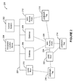
- FIGURE 2 illustrates a system 200 according to the present disclosure for providing integrated wireless reporting of location information.
- the embodiment of the system 200 shown in FIGURE 2 is for illustration only. Other embodiments of the system 200 could be used without departing from the scope of this disclosure.
- a control system 202 communicates via a communication network 226 and RF gateways 208 and 209 with process control elements (not shown) of the system 200.
- the control system 202 also communicates with an integrated location server 204 via the communication network 226.
- the integrated location server 204 is operable to calculate locations of integrated location tags 214, 216 and 218.
- the tags 214, 216 and 218 include both UWB and WiFi transmitters. In other embodiments of the disclosure, however, integrated location tags may employ other combinations of location detection technologies.
- the integrated location tag 216 may be in a location served only by a UWB receiver 210 and a UWB receiver 222.
- the UWB receiver 210 may receive an RF signal in the UWB format sent by the tag 216.
- the UWB receiver 210 may then detect information relating to the location of the tag 216 and send that information to the integrated location server 204 via the communication network 226.
- the UWB receiver 222 may also receive an RF signal in the UWB format sent by the tag 216.
- the UWB receiver 222 may then detect information relating to the location of the tag 216 and send that information to the integrated location server 204 via a communication link 224 to a WiFi access point 220, which wirelessly sends the information to the integrated location server 204 via the RF gateways 208 and 209 and the communication network 226.
- the integrated location tag 218 may be in a location served only by a WiFi access point 212 and the WiFi access point 220.
- the WiFi access point 212 may receive an RF signal in the WiFi format sent by the tag 218.
- the WiFi access point 212 may then detect information relating to the location of the tag 218 and send that information to the integrated location server 204 via the communication network 226.
- the WiFi access point 220 may also receive an RF signal in the WiFi format sent by the tag 218.
- the WiFi access point 220 may then detect information relating to the location of the tag 218 and wirelessly send the information to the integrated location server 204 via the RF gateways 208 and 209 and the communication network 226.
- the integrated location tag 214 may be in a location served by the WiFi access point 220 and the UWB receiver 222.
- the UWB receiver 222 may receive an RF signal in the UWB format sent by the tag 214.
- the UWB receiver 222 may then detect information relating to the location of the tag 214 and send that information to the integrated location server 204 via the communication link 224 to the WiFi access point 220, which wirelessly sends the information to the integrated location server 204 via the RF gateways 208 and 209 and the communication network 226.
- the WiFi access point 220 may also receive an RF signal in the WiFi format sent by the tag 214.
- the WiFi access point 220 may then detect information relating to the location of the tag 214 and wirelessly send the information to the integrated location server 204 via the RF gateways 208 and 209 and the communication network 226.
- the WiFi access point 220 is able to communicate with both the RF gateways 208 and 209, two wireless communications pathways are established between the WiFi access point 220 an the integrated location server 204. As a result, an interruption to one of the two communication paths may occur without preventing the integrated location server 204 from continuing to receive location information from the WiFi access point 220 and the UWB receiver 222.
- FIGURE 2 illustrates one example of a system for providing integrated wireless reporting of location information
- various changes may be made to FIGURE 2 .
- the layout and arrangement of the system could vary, and any number of tags, access points, location receivers, gateways, networks, servers, and control systems could be used or supported.
- While only integrated location tags are shown in the system 200, it will be understood that single format tags (such as those shown in the system 100) may also be used in the system 200.
- WiFi Wireless Fidelity
- UWB Ultra-Widelity
- ZigBee ZigBee
- components could be combined or omitted and additional components could be added in the system 200 according to particular needs.
- wireless communication of system 200 is described as radio frequency communication, it will be understood that other types of wireless communication, such as infrared, may be used.
- system 200 while described as being used to providing wireless reporting of location information in an industrial facility, the system 200 could be used to provide wireless reporting of location information in any other type of environment.
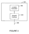
- FIGURE 3 illustrates an integrated location server 300 according to the present disclosure.
- the embodiment of the device 300 shown in FIGURE 3 is for illustration only. Other embodiments of the server 300 could be used without departing from the scope of this disclosure. Also, for ease of explanation, the server 300 is described with respect to the system 200 of FIGURE 2 . The node 300 could be used in any suitable system.
- the integrated location server 300 includes a location calculator 302 and a network interface 304.
- the network interface 304 couples the location calculator 302 to a communication network 306, which may be the communication network 226 of FIGURE 2 .
- the integrated location server 300 may receive information via the communication network 306 relating to a location of a location detection tag from location detection receivers using a plurality RF formats.
- the location calculator 302 receives the information via the network interface 304 and may then calculate a location for the tag.
- the location calculator receives a message from the control system 202 indicating that information determined from RF signals in a first format (“first format information”) is preferable over information determined from RF signals received in a second format (“second format information").
- first format information information determined from RF signals in a first format
- second format information information determined from RF signals received in a second format
- the location calculator 302 may calculate the location of the tag from the second format information.
- the location calculator 302 may resume calculating the location of the tag from the preferred first format information.
- a location detection tag transmits a unique identifier identifying the tag.
- the location calculator 302 may receive a message from the control system 202 indicating that the location of a specified tag is preferably to be calculated from first format information, identifying the tag by its unique identifier. In response to such a message, when the location calculator 302 receives both first format information and second format information, it calculates the location of the specified tag from the first format information. However, where the location calculator 302 only receives second format information, the location calculator 302 may calculate the location of the specified tag from the received second format information. Once the location calculator 302 is again receiving first format information, it may resume calculating the location of the specified tag from the preferred first format information.
- FIGURE 3 illustrates one example of an integrated tracking receiver and wireless relay node
- the layout and arrangement of the node 300 could vary, and any number of tracking receivers, wireless nodes, numbers and types of antennas could be used or supported.
- components could be combined or omitted and additional components could be added in the node 300 according to particular needs.
- various functions described above are implemented or supported by a computer program that is formed from computer readable program code and that is embodied in a computer readable medium.
- computer readable program code includes any type of computer code, including source code, object code, and executable code.
- computer readable medium includes any type of medium capable of being accessed by a computer, such as read only memory (ROM), random access memory (RAM), a hard disk drive, a compact disc (CD), a digital video disc (DVD), or any other type of memory.
- Couple and its derivatives refer to any direct or indirect communication between two or more elements, whether or not those elements are in physical contact with one another.
- application and “program” refer to one or more computer programs, software components, sets of instructions, procedures, functions, objects, classes, instances, related data, or a portion thereof adapted for implementation in a suitable computer code (including source code, object code, or executable code).
- transmit and “communicate,” as well as derivatives thereof, encompass both direct and indirect communication.
- the term “or” is inclusive, meaning and/or.
- controller means any device, system, or part thereof that controls at least one operation.
- a controller may be implemented in hardware, firmware, software, or some combination of at least two of the same.
- the functionality associated with any particular controller may be centralized or distributed, whether locally or remotely.
Landscapes
- Physics & Mathematics (AREA)
- Engineering & Computer Science (AREA)
- General Physics & Mathematics (AREA)
- Radar, Positioning & Navigation (AREA)
- Remote Sensing (AREA)
- Mobile Radio Communication Systems (AREA)
Claims (10)
- System, das Folgendes aufweist:einen Ortsbestimmungs(LD)-Sender, der betriebsfähig ist, um ein erstes Hochfrequenz(HF)-Signal in einem ersten Format und ein zweites HF-Signal in einem zweiten Format zu senden;einen ersten LD-Empfänger, der für Folgendes betriebsfähig ist:Empfangen des ersten HF-Signals von dem LD-Sender; undBestimmen erster Informationen, die einen Ort des LD-Senders betreffen, von dem ersten HF-Signal;einen zweiten LD-Empfänger, der für Folgendes betriebsfähig ist:Empfangen des zweiten HF-Signals von dem LD-Sender; undBestimmen zweiter Informationen, die den Ort des LD-Senders betreffen, von dem zweiten HF-Signal; undeinen LD-Server, der für Folgendes betriebsfähig ist:drahtloses Empfangen der ersten Informationen und der zweiten Informationen von dem ersten LD-Empfänger beziehungsweise dem zweiten LD-Empfänger;Empfangen einer Nachricht, die Informationen aufweist, die identifizieren, dass die Informationen von einem der LD-Empfänger gegenüber den Informationen von einem anderen der LD-Empfänger zur Verwendung bei der Berechnung des Ortes des LD-Senders bevorzugt werden, von einem industriellen Prozesssteuerungssystem;Identifizieren von bevorzugten von den ersten Informationen und den zweiten Informationen zur Verwendung bei der Berechnung des Ortes des LD-Senders von der Nachricht; undBerechnen des Ortes des LD-Senders von den bevorzugten von den ersten Informationen und den zweiten Informationen.
- System nach Anspruch 1, wobei:der LD-Sender ferner betriebsfähig ist, um eine Kennung in mindestens einem von dem ersten HF-Signal und dem zweiten HF-Signal zu senden; undder LD-Server ferner für Folgendes betriebsfähig ist:Empfangen der Kennung von mindestens einem von dem ersten LD-Empfänger und dem zweiten LD-Empfänger;Identifizieren der bevorzugten von den ersten Informationen und den zweiten Informationen von der Nachricht auf der Grundlage der Kennung, wobei die Nachricht Informationen aufweist, die identifizieren, dass die Informationen von einem der LD-Empfänger gegenüber den Informationen von einem anderen der LD-Empfänger für den LD-Sender bevorzugt werden, der die Kennung aufweist; undals Reaktion auf die Kennung, Berechnen des Ortes des LD-Senders von den bevorzugten von den ersten Informationen und den zweiten Informationen.
- System nach Anspruch 2, wobei der LD-Server ferner betriebsfähig ist, um den Ort des LD-Senders von den anderen von den ersten Informationen und den zweiten Informationen als Reaktion auf einen Fehler beim Empfangen der bevorzugten von den ersten Informationen und den zweiten Informationen zu berechnen.
- System nach Anspruch 1, wobei der LD-Server ferner betriebsfähig ist, um die ersten Informationen und die zweiten Informationen drahtlos über mehrere Zwischenknoten zu empfangen.
- Vorrichtung, die Folgendes aufweist:eine Netzschnittstelle; undeinen Ortsberechner, der für Folgendes betriebsfähig ist:Empfangen von ersten Informationen von einem ersten Ortsbestimmungs(LD)-Empfänger über die Netzschnittstelle, wobei die ersten Informationen einen Ort eines LD-Senders betreffen und von einem ersten Hochfrequenz(HF)-Signal in einem ersten HF-Format bestimmt werden, das von dem LD-Sender empfangen wird;Empfangen von zweiten Informationen von einem zweiten LD-Empfänger über die Netzschnittstelle, wobei die zweiten Informationen den Ort des LD-Senders betreffen und von einem zweiten HF-Signal in einem zweiten HF-Format bestimmt werden, das von dem LD-Sender empfangen wird;Empfangen einer Nachricht, die Informationen aufweist, die identifizieren, dass die Informationen von einem der LD-Empfänger gegenüber den Informationen von einem anderen der LD-Empfänger zur Verwendung bei der Berechnung des Ortes des LD-Senders bevorzugt werden, von einem industriellen Prozesssteuerungssystem;Identifizieren von bevorzugten von den ersten Informationen und den zweiten Informationen zur Verwendung bei der Berechnung des Ortes des LD-Senders von der Nachricht; undBerechnen des Ortes des LD-Senders von den bevorzugten von den ersten Informationen und den zweiten Informationen.
- Vorrichtung nach Anspruch 5, wobei der Ortsberechner ferner für Folgendes betriebsfähig ist:Empfangen einer Kennung des LD-Senders von einem von dem ersten und dem zweiten LD-Empfänger über die Netzschnittstelle;Identifizieren der bevorzugten von den ersten Informationen und den zweiten Informationen von der Nachricht auf der Grundlage der Kennung, wobei die Nachricht Informationen aufweist, die identifizieren, dass die Informationen von einem der LD-Empfänger gegenüber den Informationen von einem anderen der LD-Empfänger für den LD-Sender bevorzugt werden, der die Kennung aufweist; undals Reaktion auf die Kennung, Berechnen des Ortes des LD-Senders von den bevorzugten von den ersten Informationen und den zweiten Informationen.
- Vorrichtung nach Anspruch 6, wobei der Ortsberechner ferner betriebsfähig ist, um den Ort des LD-Senders von den anderen von den ersten Informationen und den zweiten Informationen als Reaktion auf einen Fehler beim Empfangen der bevorzugten von den ersten Informationen und den zweiten Informationen zu berechnen.
- Verfahren, das Folgendes aufweist:Senden eines ersten Hochfrequenz(HF)-Signals in einem ersten Format von einem Ortsbestimmungs(LD)-Sender;Senden eines zweiten HF-Signals in einem zweiten Format von dem LD-Sender;Empfangen des ersten HF-Signals in einem ersten LD-Empfänger und Bestimmen von ersten Informationen, die einen Ort des LD-Senders betreffen, von dem ersten HF-Signal;Empfangen des zweiten HF-Signals in einem zweiten LD-Empfänger und Bestimmen von zweiten Informationen, die den Ort des LD-Senders betreffen, von dem zweiten HF-Signal;drahtloses Empfangen der ersten Informationen und der zweiten Informationen in einem LD-Server;Empfangen einer Nachricht, die Informationen aufweist, die identifizieren, dass die Informationen von einem der LD-Empfänger gegenüber den Informationen von einem anderen der LD-Empfänger zur Verwendung bei der Berechnung des Ortes des LD-Senders bevorzugt werden, von einem industriellen Prozesssteuerungssystem an dem LD-Server;Identifizieren von bevorzugten von den ersten Informationen und den zweiten Informationen zur Verwendung bei der Berechnung des Ortes des LD-Senders von der Nachricht; undBerechnen des Ortes des LD-Senders an dem LD-Server von den bevorzugten von den ersten Informationen und den zweiten Informationen.
- Verfahren nach Anspruch 8, das ferner Folgendes aufweist:Senden einer Kennung in mindestens einem von dem ersten HF-Signal und dem zweiten HF-Signal;Empfangen der Kennung von mindestens einem von dem ersten LD-Empfänger und dem zweiten LD-Empfänger in dem LD-Server;Identifizieren der bevorzugten von den ersten Informationen und den zweiten Informationen von der Nachricht auf der Grundlage der Kennung, wobei die Nachricht Informationen aufweist, die identifizieren, dass die Informationen von einem der LD-Empfänger gegenüber den Informationen von einem anderen der LD-Empfänger für den LD-Sender bevorzugt werden, der die Kennung aufweist; und als Reaktion auf die Kennung, Berechnen des Ortes des LD-Senders von den bevorzugten von den ersten Informationen und den zweiten Informationen.
- Verfahren nach Anspruch 9, das ferner das Berechnen des Ortes des LD-Senders von den anderen von den ersten Informationen und den zweiten Informationen als Reaktion auf einen Fehler beim Empfangen der bevorzugten von den ersten Informationen und den zweiten Informationen aufweist.
Applications Claiming Priority (2)
| Application Number | Priority Date | Filing Date | Title |
|---|---|---|---|
| US11/879,543 US8265651B2 (en) | 2007-07-17 | 2007-07-17 | System and apparatus for integrated wireless location detection |
| PCT/US2008/069582 WO2009012103A1 (en) | 2007-07-17 | 2008-07-10 | System and apparatus for integrated wireless location detection |
Publications (3)
| Publication Number | Publication Date |
|---|---|
| EP2168265A1 EP2168265A1 (de) | 2010-03-31 |
| EP2168265A4 EP2168265A4 (de) | 2011-07-20 |
| EP2168265B1 true EP2168265B1 (de) | 2015-10-07 |
Family
ID=40259996
Family Applications (1)
| Application Number | Title | Priority Date | Filing Date |
|---|---|---|---|
| EP08772495.1A Not-in-force EP2168265B1 (de) | 2007-07-17 | 2008-07-10 | System und vorrichtung für integrierte drahtlose ortserkennung |
Country Status (5)
| Country | Link |
|---|---|
| US (1) | US8265651B2 (de) |
| EP (1) | EP2168265B1 (de) |
| CN (1) | CN101803240A (de) |
| CA (1) | CA2693258A1 (de) |
| WO (1) | WO2009012103A1 (de) |
Families Citing this family (10)
| Publication number | Priority date | Publication date | Assignee | Title |
|---|---|---|---|---|
| US8633853B2 (en) | 2008-07-31 | 2014-01-21 | Honeywell International Inc. | Method and apparatus for location detection using GPS and WiFi/WiMAX |
| US9500736B2 (en) * | 2008-07-31 | 2016-11-22 | Honeywell International Inc. | System and method for providing self-locating wireless sensors |
| US8755814B2 (en) * | 2008-07-31 | 2014-06-17 | Honeywell International Inc. | Method and apparatus for intermittent location reporting |
| US8350666B2 (en) | 2008-10-15 | 2013-01-08 | Honeywell International Inc. | Apparatus and method for location-based access control in wireless networks |
| RU2419106C1 (ru) * | 2009-11-09 | 2011-05-20 | Государственное образовательное учреждение высшего профессионального образования "Военная академия связи имени С.М. Буденного" Министерства обороны Российской Федерации | Способ и устройство определения координат источника радиоизлучения |
| RU2423719C1 (ru) * | 2010-05-11 | 2011-07-10 | Общество с ограниченной ответственностью "Специальный Технологический Центр" | Способ адаптивного измерения пространственных параметров источников радиоизлучений и устройство для его осуществления |
| ES2401228B1 (es) * | 2011-03-01 | 2014-05-05 | Telefónica, S.A. | Método para localización móvil en una red inalámbrica que ofrece servicios basados en localización |
| US10298939B2 (en) | 2011-06-22 | 2019-05-21 | Qualcomm Incorporated | Quantization in video coding |
| FR3077141B1 (fr) * | 2018-01-22 | 2020-07-03 | Kerlink | Procede de geolocalisation d'un dispositif emetteur de signal |
| CN108769901B (zh) * | 2018-05-18 | 2020-03-17 | 华南农业大学 | 一种基于uwb技术的实验室设备管理系统和方法 |
Family Cites Families (22)
| Publication number | Priority date | Publication date | Assignee | Title |
|---|---|---|---|---|
| US6570487B1 (en) | 1997-01-24 | 2003-05-27 | Axcess Inc. | Distributed tag reader system and method |
| US6034603A (en) | 1997-01-24 | 2000-03-07 | Axcess, Inc. | Radio tag system and method with improved tag interference avoidance |
| US6243587B1 (en) * | 1997-12-10 | 2001-06-05 | Ericsson Inc. | Method and system for determining position of a mobile transmitter |
| US7005985B1 (en) | 1999-07-20 | 2006-02-28 | Axcess, Inc. | Radio frequency identification system and method |
| US7286158B1 (en) | 1999-12-22 | 2007-10-23 | Axcess International Inc. | Method and system for providing integrated remote monitoring services |
| US7019663B2 (en) * | 2002-08-08 | 2006-03-28 | Symbol Technologies, Inc. | RF tracking system and method |
| JP3766407B2 (ja) | 2003-08-01 | 2006-04-12 | 鹿島建設株式会社 | 消防隊員の位置検知方法 |
| US7904244B2 (en) | 2003-11-18 | 2011-03-08 | Sarimo Technologies, LLC | Determining a location or position using information from multiple location and positioning technologies and applications using such a determined location or position |
| EP1779680A4 (de) | 2004-07-30 | 2008-09-17 | Reva Systems Corpoartion | Rfid-etiketten-datenakquisitionssystem |
| US7821449B2 (en) | 2005-01-12 | 2010-10-26 | Qualcomm Incorporated | Base station almanac assisted positioning |
| CN101137913A (zh) * | 2005-03-02 | 2008-03-05 | 富士通株式会社 | 位置检测系统以及rfid终端 |
| US7471242B2 (en) | 2005-12-08 | 2008-12-30 | Honeywell International Inc. | Method and apparatus for installing and/or determining the position of a receiver of a tracking system |
| US20070132576A1 (en) | 2005-12-08 | 2007-06-14 | Honeywell International Inc. | Method and apparatus for tracking persons |
| US20070132577A1 (en) | 2005-12-09 | 2007-06-14 | Honeywell International Inc. | Method and apparatus for estimating the location of a signal transmitter |
| US20070205886A1 (en) | 2006-03-01 | 2007-09-06 | Huseth Steve D | RF/acoustic person locator system |
| US20070241901A1 (en) | 2006-03-31 | 2007-10-18 | Honeywell International Inc. | System and method for object tracking via tag readings |
| US7420510B2 (en) | 2006-04-17 | 2008-09-02 | Honeywell International Inc. | Location and tracking of people with combined use of RF infrastructure and dead reckoning modules |
| US8081996B2 (en) | 2006-05-16 | 2011-12-20 | Honeywell International Inc. | Integrated infrastructure for coexistence of WI-FI networks with other networks |
| US20080109098A1 (en) | 2006-11-08 | 2008-05-08 | Honeywell International Inc. | Apparatus and method for integrating people and asset tracking information into a process control system |
| US8332063B2 (en) | 2006-11-08 | 2012-12-11 | Honeywell International Inc. | Apparatus and method for process control using people and asset tracking information |
| US8396280B2 (en) | 2006-11-29 | 2013-03-12 | Honeywell International Inc. | Apparatus and method for inspecting assets in a processing or other environment |
| US7688198B2 (en) | 2006-11-29 | 2010-03-30 | Honeywell International Inc. | Apparatus and method for monitoring hazardous materials in a processing or other environment |
-
2007
- 2007-07-17 US US11/879,543 patent/US8265651B2/en active Active
-
2008
- 2008-07-10 EP EP08772495.1A patent/EP2168265B1/de not_active Not-in-force
- 2008-07-10 CA CA2693258A patent/CA2693258A1/en not_active Abandoned
- 2008-07-10 WO PCT/US2008/069582 patent/WO2009012103A1/en not_active Ceased
- 2008-07-10 CN CN200880107443A patent/CN101803240A/zh active Pending
Also Published As
| Publication number | Publication date |
|---|---|
| US8265651B2 (en) | 2012-09-11 |
| US20090021390A1 (en) | 2009-01-22 |
| WO2009012103A1 (en) | 2009-01-22 |
| EP2168265A4 (de) | 2011-07-20 |
| CA2693258A1 (en) | 2009-01-22 |
| CN101803240A (zh) | 2010-08-11 |
| EP2168265A1 (de) | 2010-03-31 |
Similar Documents
| Publication | Publication Date | Title |
|---|---|---|
| EP2168265B1 (de) | System und vorrichtung für integrierte drahtlose ortserkennung | |
| US7768394B2 (en) | System and apparatus for integrated location detection and wireless communications | |
| US20240227885A9 (en) | Methods and systems for decentralized train control | |
| US7982614B2 (en) | Method and apparatus for wireless asset tracking using asset tags with motion sensors | |
| EP2532198B1 (de) | Mobilfunknetz in innenräumen mit positionsinformationen eines mobilgeräts | |
| CN101349744B (zh) | 一种基于Zigbee网络平台的井下人员跟踪定位方法及其系统 | |
| US20090045939A1 (en) | Locating devices using wireless communications | |
| US20130060351A1 (en) | Asset tracking in process control environments | |
| US8755814B2 (en) | Method and apparatus for intermittent location reporting | |
| EP1859605A1 (de) | Sicheres verfahren und vorrichtung zum abrufen von netzknotenkennungen in drahtlosen netzwerken | |
| WO2011013084A1 (en) | Asset tracking system and method | |
| JP7693834B2 (ja) | 独立したuwbアンカー同期によるuwbの位置特定 | |
| KR101850610B1 (ko) | Rtls 기반의 실시간 안전, 보안 및 위치추적 통합관제시스템 | |
| KR102422614B1 (ko) | 비콘 및 이를 이용한 도난감지방법 | |
| CN107851239B (zh) | 智能无线资产跟踪 | |
| US8428511B1 (en) | System and method for a high available and survivable communication system | |
| KR100660150B1 (ko) | 다중 안테나를 사용하는 무선 주파수 식별 태그의감지장치 및 방법 | |
| EP4484994A1 (de) | Innenraumpositionierungs- und -führungssystem auf basis von extrem niederfrequenten magnetfeldbaken und mobilen vorrichtungen sowie zugehöriges verfahren | |
| US12581272B2 (en) | Real-time location system and method using sensor-to-sensor data collection | |
| JP2006010311A (ja) | 中継方式障害物検出システムおよび方法 | |
| KR20090083868A (ko) | 다중 안테나에 의한 영역별 무선 주파수 식별 태그의 감지장치 및 방법 | |
| US12464391B2 (en) | System and method for monitoring a sensor network | |
| US20180124562A1 (en) | Virtual perimeter system and method | |
| EP2833684B1 (de) | Sensoren-Netzwerk für die Innenortung mobiler Einheiten | |
| KR20090016213A (ko) | 다중 안테나에 의한 영역별 무선 주파수 태그의 감지장치및 방법 |
Legal Events
| Date | Code | Title | Description |
|---|---|---|---|
| PUAI | Public reference made under article 153(3) epc to a published international application that has entered the european phase |
Free format text: ORIGINAL CODE: 0009012 |
|
| 17P | Request for examination filed |
Effective date: 20100108 |
|
| AK | Designated contracting states |
Kind code of ref document: A1 Designated state(s): AT BE BG CH CY CZ DE DK EE ES FI FR GB GR HR HU IE IS IT LI LT LU LV MC MT NL NO PL PT RO SE SI SK TR |
|
| AX | Request for extension of the european patent |
Extension state: AL BA MK RS |
|
| RIN1 | Information on inventor provided before grant (corrected) |
Inventor name: AMIDI, SOROUSHC/O HONEYWELL INTERNATIONAL INC. |
|
| DAX | Request for extension of the european patent (deleted) | ||
| A4 | Supplementary search report drawn up and despatched |
Effective date: 20110621 |
|
| 17Q | First examination report despatched |
Effective date: 20110629 |
|
| GRAP | Despatch of communication of intention to grant a patent |
Free format text: ORIGINAL CODE: EPIDOSNIGR1 |
|
| INTG | Intention to grant announced |
Effective date: 20150708 |
|
| GRAS | Grant fee paid |
Free format text: ORIGINAL CODE: EPIDOSNIGR3 |
|
| GRAA | (expected) grant |
Free format text: ORIGINAL CODE: 0009210 |
|
| AK | Designated contracting states |
Kind code of ref document: B1 Designated state(s): AT BE BG CH CY CZ DE DK EE ES FI FR GB GR HR HU IE IS IT LI LT LU LV MC MT NL NO PL PT RO SE SI SK TR |
|
| REG | Reference to a national code |
Ref country code: GB Ref legal event code: FG4D |
|
| REG | Reference to a national code |
Ref country code: AT Ref legal event code: REF Ref document number: 754275 Country of ref document: AT Kind code of ref document: T Effective date: 20151015 Ref country code: CH Ref legal event code: EP |
|
| REG | Reference to a national code |
Ref country code: IE Ref legal event code: FG4D |
|
| REG | Reference to a national code |
Ref country code: DE Ref legal event code: R096 Ref document number: 602008040534 Country of ref document: DE |
|
| RAP2 | Party data changed (patent owner data changed or rights of a patent transferred) |
Owner name: HONEYWELL INTERNATIONAL INC. |
|
| REG | Reference to a national code |
Ref country code: NL Ref legal event code: MP Effective date: 20151007 |
|
| REG | Reference to a national code |
Ref country code: AT Ref legal event code: MK05 Ref document number: 754275 Country of ref document: AT Kind code of ref document: T Effective date: 20151007 |
|
| REG | Reference to a national code |
Ref country code: LT Ref legal event code: MG4D |
|
| PG25 | Lapsed in a contracting state [announced via postgrant information from national office to epo] |
Ref country code: NO Free format text: LAPSE BECAUSE OF FAILURE TO SUBMIT A TRANSLATION OF THE DESCRIPTION OR TO PAY THE FEE WITHIN THE PRESCRIBED TIME-LIMIT Effective date: 20160107 Ref country code: NL Free format text: LAPSE BECAUSE OF FAILURE TO SUBMIT A TRANSLATION OF THE DESCRIPTION OR TO PAY THE FEE WITHIN THE PRESCRIBED TIME-LIMIT Effective date: 20151007 Ref country code: IS Free format text: LAPSE BECAUSE OF FAILURE TO SUBMIT A TRANSLATION OF THE DESCRIPTION OR TO PAY THE FEE WITHIN THE PRESCRIBED TIME-LIMIT Effective date: 20160207 Ref country code: LT Free format text: LAPSE BECAUSE OF FAILURE TO SUBMIT A TRANSLATION OF THE DESCRIPTION OR TO PAY THE FEE WITHIN THE PRESCRIBED TIME-LIMIT Effective date: 20151007 Ref country code: IT Free format text: LAPSE BECAUSE OF FAILURE TO SUBMIT A TRANSLATION OF THE DESCRIPTION OR TO PAY THE FEE WITHIN THE PRESCRIBED TIME-LIMIT Effective date: 20151007 Ref country code: ES Free format text: LAPSE BECAUSE OF FAILURE TO SUBMIT A TRANSLATION OF THE DESCRIPTION OR TO PAY THE FEE WITHIN THE PRESCRIBED TIME-LIMIT Effective date: 20151007 Ref country code: HR Free format text: LAPSE BECAUSE OF FAILURE TO SUBMIT A TRANSLATION OF THE DESCRIPTION OR TO PAY THE FEE WITHIN THE PRESCRIBED TIME-LIMIT Effective date: 20151007 |
|
| PG25 | Lapsed in a contracting state [announced via postgrant information from national office to epo] |
Ref country code: AT Free format text: LAPSE BECAUSE OF FAILURE TO SUBMIT A TRANSLATION OF THE DESCRIPTION OR TO PAY THE FEE WITHIN THE PRESCRIBED TIME-LIMIT Effective date: 20151007 Ref country code: SE Free format text: LAPSE BECAUSE OF FAILURE TO SUBMIT A TRANSLATION OF THE DESCRIPTION OR TO PAY THE FEE WITHIN THE PRESCRIBED TIME-LIMIT Effective date: 20151007 Ref country code: PT Free format text: LAPSE BECAUSE OF FAILURE TO SUBMIT A TRANSLATION OF THE DESCRIPTION OR TO PAY THE FEE WITHIN THE PRESCRIBED TIME-LIMIT Effective date: 20160208 Ref country code: FI Free format text: LAPSE BECAUSE OF FAILURE TO SUBMIT A TRANSLATION OF THE DESCRIPTION OR TO PAY THE FEE WITHIN THE PRESCRIBED TIME-LIMIT Effective date: 20151007 Ref country code: LV Free format text: LAPSE BECAUSE OF FAILURE TO SUBMIT A TRANSLATION OF THE DESCRIPTION OR TO PAY THE FEE WITHIN THE PRESCRIBED TIME-LIMIT Effective date: 20151007 Ref country code: PL Free format text: LAPSE BECAUSE OF FAILURE TO SUBMIT A TRANSLATION OF THE DESCRIPTION OR TO PAY THE FEE WITHIN THE PRESCRIBED TIME-LIMIT Effective date: 20151007 Ref country code: GR Free format text: LAPSE BECAUSE OF FAILURE TO SUBMIT A TRANSLATION OF THE DESCRIPTION OR TO PAY THE FEE WITHIN THE PRESCRIBED TIME-LIMIT Effective date: 20160108 |
|
| REG | Reference to a national code |
Ref country code: FR Ref legal event code: PLFP Year of fee payment: 9 |
|
| REG | Reference to a national code |
Ref country code: DE Ref legal event code: R097 Ref document number: 602008040534 Country of ref document: DE |
|
| PG25 | Lapsed in a contracting state [announced via postgrant information from national office to epo] |
Ref country code: CZ Free format text: LAPSE BECAUSE OF FAILURE TO SUBMIT A TRANSLATION OF THE DESCRIPTION OR TO PAY THE FEE WITHIN THE PRESCRIBED TIME-LIMIT Effective date: 20151007 |
|
| PLBE | No opposition filed within time limit |
Free format text: ORIGINAL CODE: 0009261 |
|
| STAA | Information on the status of an ep patent application or granted ep patent |
Free format text: STATUS: NO OPPOSITION FILED WITHIN TIME LIMIT |
|
| PG25 | Lapsed in a contracting state [announced via postgrant information from national office to epo] |
Ref country code: EE Free format text: LAPSE BECAUSE OF FAILURE TO SUBMIT A TRANSLATION OF THE DESCRIPTION OR TO PAY THE FEE WITHIN THE PRESCRIBED TIME-LIMIT Effective date: 20151007 Ref country code: RO Free format text: LAPSE BECAUSE OF FAILURE TO SUBMIT A TRANSLATION OF THE DESCRIPTION OR TO PAY THE FEE WITHIN THE PRESCRIBED TIME-LIMIT Effective date: 20151007 Ref country code: DK Free format text: LAPSE BECAUSE OF FAILURE TO SUBMIT A TRANSLATION OF THE DESCRIPTION OR TO PAY THE FEE WITHIN THE PRESCRIBED TIME-LIMIT Effective date: 20151007 Ref country code: SK Free format text: LAPSE BECAUSE OF FAILURE TO SUBMIT A TRANSLATION OF THE DESCRIPTION OR TO PAY THE FEE WITHIN THE PRESCRIBED TIME-LIMIT Effective date: 20151007 |
|
| 26N | No opposition filed |
Effective date: 20160708 |
|
| PG25 | Lapsed in a contracting state [announced via postgrant information from national office to epo] |
Ref country code: SI Free format text: LAPSE BECAUSE OF FAILURE TO SUBMIT A TRANSLATION OF THE DESCRIPTION OR TO PAY THE FEE WITHIN THE PRESCRIBED TIME-LIMIT Effective date: 20151007 |
|
| PG25 | Lapsed in a contracting state [announced via postgrant information from national office to epo] |
Ref country code: BE Free format text: LAPSE BECAUSE OF FAILURE TO SUBMIT A TRANSLATION OF THE DESCRIPTION OR TO PAY THE FEE WITHIN THE PRESCRIBED TIME-LIMIT Effective date: 20151007 |
|
| REG | Reference to a national code |
Ref country code: CH Ref legal event code: PL |
|
| PG25 | Lapsed in a contracting state [announced via postgrant information from national office to epo] |
Ref country code: MC Free format text: LAPSE BECAUSE OF FAILURE TO SUBMIT A TRANSLATION OF THE DESCRIPTION OR TO PAY THE FEE WITHIN THE PRESCRIBED TIME-LIMIT Effective date: 20151007 |
|
| PG25 | Lapsed in a contracting state [announced via postgrant information from national office to epo] |
Ref country code: LI Free format text: LAPSE BECAUSE OF NON-PAYMENT OF DUE FEES Effective date: 20160731 Ref country code: CH Free format text: LAPSE BECAUSE OF NON-PAYMENT OF DUE FEES Effective date: 20160731 |
|
| REG | Reference to a national code |
Ref country code: IE Ref legal event code: MM4A |
|
| REG | Reference to a national code |
Ref country code: FR Ref legal event code: PLFP Year of fee payment: 10 |
|
| PG25 | Lapsed in a contracting state [announced via postgrant information from national office to epo] |
Ref country code: IE Free format text: LAPSE BECAUSE OF NON-PAYMENT OF DUE FEES Effective date: 20160710 |
|
| PG25 | Lapsed in a contracting state [announced via postgrant information from national office to epo] |
Ref country code: LU Free format text: LAPSE BECAUSE OF NON-PAYMENT OF DUE FEES Effective date: 20160710 |
|
| PG25 | Lapsed in a contracting state [announced via postgrant information from national office to epo] |
Ref country code: CY Free format text: LAPSE BECAUSE OF FAILURE TO SUBMIT A TRANSLATION OF THE DESCRIPTION OR TO PAY THE FEE WITHIN THE PRESCRIBED TIME-LIMIT Effective date: 20151007 Ref country code: HU Free format text: LAPSE BECAUSE OF FAILURE TO SUBMIT A TRANSLATION OF THE DESCRIPTION OR TO PAY THE FEE WITHIN THE PRESCRIBED TIME-LIMIT; INVALID AB INITIO Effective date: 20080710 |
|
| PG25 | Lapsed in a contracting state [announced via postgrant information from national office to epo] |
Ref country code: MT Free format text: LAPSE BECAUSE OF NON-PAYMENT OF DUE FEES Effective date: 20160731 Ref country code: TR Free format text: LAPSE BECAUSE OF FAILURE TO SUBMIT A TRANSLATION OF THE DESCRIPTION OR TO PAY THE FEE WITHIN THE PRESCRIBED TIME-LIMIT Effective date: 20151007 |
|
| REG | Reference to a national code |
Ref country code: FR Ref legal event code: PLFP Year of fee payment: 11 |
|
| PG25 | Lapsed in a contracting state [announced via postgrant information from national office to epo] |
Ref country code: BG Free format text: LAPSE BECAUSE OF FAILURE TO SUBMIT A TRANSLATION OF THE DESCRIPTION OR TO PAY THE FEE WITHIN THE PRESCRIBED TIME-LIMIT Effective date: 20151007 |
|
| PGFP | Annual fee paid to national office [announced via postgrant information from national office to epo] |
Ref country code: FR Payment date: 20180726 Year of fee payment: 11 |
|
| PGFP | Annual fee paid to national office [announced via postgrant information from national office to epo] |
Ref country code: GB Payment date: 20180731 Year of fee payment: 11 |
|
| PGFP | Annual fee paid to national office [announced via postgrant information from national office to epo] |
Ref country code: DE Payment date: 20180928 Year of fee payment: 11 |
|
| REG | Reference to a national code |
Ref country code: DE Ref legal event code: R119 Ref document number: 602008040534 Country of ref document: DE |
|
| GBPC | Gb: european patent ceased through non-payment of renewal fee |
Effective date: 20190710 |
|
| PG25 | Lapsed in a contracting state [announced via postgrant information from national office to epo] |
Ref country code: GB Free format text: LAPSE BECAUSE OF NON-PAYMENT OF DUE FEES Effective date: 20190710 Ref country code: DE Free format text: LAPSE BECAUSE OF NON-PAYMENT OF DUE FEES Effective date: 20200201 |
|
| PG25 | Lapsed in a contracting state [announced via postgrant information from national office to epo] |
Ref country code: FR Free format text: LAPSE BECAUSE OF NON-PAYMENT OF DUE FEES Effective date: 20190731 |