EP2167914B1 - System to measure the transit time position(s) of pulses in a time domain data - Google Patents
System to measure the transit time position(s) of pulses in a time domain data Download PDFInfo
- Publication number
- EP2167914B1 EP2167914B1 EP08796176.9A EP08796176A EP2167914B1 EP 2167914 B1 EP2167914 B1 EP 2167914B1 EP 08796176 A EP08796176 A EP 08796176A EP 2167914 B1 EP2167914 B1 EP 2167914B1
- Authority
- EP
- European Patent Office
- Prior art keywords
- thz
- waveform
- sample
- pulse
- amplitude point
- Prior art date
- Legal status (The legal status is an assumption and is not a legal conclusion. Google has not performed a legal analysis and makes no representation as to the accuracy of the status listed.)
- Active
Links
Images








Classifications
-
- G—PHYSICS
- G01—MEASURING; TESTING
- G01C—MEASURING DISTANCES, LEVELS OR BEARINGS; SURVEYING; NAVIGATION; GYROSCOPIC INSTRUMENTS; PHOTOGRAMMETRY OR VIDEOGRAMMETRY
- G01C3/00—Measuring distances in line of sight; Optical rangefinders
- G01C3/02—Details
- G01C3/06—Use of electric means to obtain final indication
- G01C3/08—Use of electric radiation detectors
-
- G—PHYSICS
- G01—MEASURING; TESTING
- G01R—MEASURING ELECTRIC VARIABLES; MEASURING MAGNETIC VARIABLES
- G01R29/00—Arrangements for measuring or indicating electric quantities not covered by groups G01R19/00 - G01R27/00
-
- G—PHYSICS
- G01—MEASURING; TESTING
- G01B—MEASURING LENGTH, THICKNESS OR SIMILAR LINEAR DIMENSIONS; MEASURING ANGLES; MEASURING AREAS; MEASURING IRREGULARITIES OF SURFACES OR CONTOURS
- G01B7/00—Measuring arrangements characterised by the use of electric or magnetic techniques
-
- G—PHYSICS
- G01—MEASURING; TESTING
- G01N—INVESTIGATING OR ANALYSING MATERIALS BY DETERMINING THEIR CHEMICAL OR PHYSICAL PROPERTIES
- G01N21/00—Investigating or analysing materials by the use of optical means, i.e. using sub-millimetre waves, infrared, visible or ultraviolet light
- G01N21/17—Systems in which incident light is modified in accordance with the properties of the material investigated
- G01N21/25—Colour; Spectral properties, i.e. comparison of effect of material on the light at two or more different wavelengths or wavelength bands
- G01N21/31—Investigating relative effect of material at wavelengths characteristic of specific elements or molecules, e.g. atomic absorption spectrometry
- G01N21/35—Investigating relative effect of material at wavelengths characteristic of specific elements or molecules, e.g. atomic absorption spectrometry using infrared light
- G01N21/3581—Investigating relative effect of material at wavelengths characteristic of specific elements or molecules, e.g. atomic absorption spectrometry using infrared light using far infrared light; using Terahertz radiation
- G01N21/3586—Investigating relative effect of material at wavelengths characteristic of specific elements or molecules, e.g. atomic absorption spectrometry using infrared light using far infrared light; using Terahertz radiation by Terahertz time domain spectroscopy [THz-TDS]
-
- G—PHYSICS
- G01—MEASURING; TESTING
- G01N—INVESTIGATING OR ANALYSING MATERIALS BY DETERMINING THEIR CHEMICAL OR PHYSICAL PROPERTIES
- G01N23/00—Investigating or analysing materials by the use of wave or particle radiation, e.g. X-rays or neutrons, not covered by groups G01N3/00 – G01N17/00, G01N21/00 or G01N22/00
Definitions
- the present invention relates to methods to measure the transit time values for pulses in time domain waveform data. Examples will be presented using Time-Domain Terahertz data to determine sample properties. Terahertz electromagnetic radiation is potentially useful in many industrial measurement applications.
- TD-THz essentially single cycle pulses (approximately 1 ps width, Figure 1 ) of radiation are synchronously generated and detected. This synchronous method results in high fidelity measurement of the radiation's electric field strength over a waveform time window. This width of this window can vary over a wide range depending on the instrumentation used. As THz radiation pulses are very brief in time, they will contain an extremely wide band of frequencies (10 GHz up to 50 THz).
- TD-THz pulse Once a TD-THz pulse has interacted with a sample, a number of useful measurements can be extracted from acquired time-domain data. Possible measurements include, but are not limited to, sample mass, thickness, density, refractive index, density and surface variations, and spectroscopy (e.g. moisture content, polymorph identification).
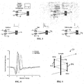
- FIG. 2 illustrates a terahertz transmitter 10 and terahertz receiver 12.
- TD-THz the changes in the THz pulses after they have interacted with material are recorded in a time-domain waveform.
- the pulse transmits through a sample 14 the pulse's arrival at the receiver will be attenuated and delayed compared to the transmission of the same pulse through an air path ( Figure 2 ).
- the amount of the pulse delay is determined by the material's group refractive index value and the amount of mass in the sample beam.
- the attenuation of the pulse is also dependent on material's refractive index (Fresnel reflection loss), the scattering of radiation with the sample and the attenuation of the pulse's frequencies by the material.
- a THz pulse travels through air with minimum timeof-flight and no loss in amplitude.
- essentially transparent solid materials e.g., plastics, paper, and cloth
- the increased time-of-flight will be proportional to the mass and index of refraction of the material.
- scattering or absorbing media such as foam or water laden cloth
- sample thickness measurement An example measurement would be sample thickness measurement. This measurement could be made in either transmission or reflection optical geometries.
- the delay of the THz pulse by the sample 14 can be used to measure thickness ( Figure 4 ).
- Line 16 represents no sample.
- Line 18 represents a thin sample.
- Line 20 represents a thick sample. This method requires determining the time position of peaks from two time-domain waveforms that were acquired at two different times (i.e., sample in and out of the beam). This method can result in offset or scaling errors if the position of either peak is shifted due to instrumental or environmental conditions.
- THz pulses will reflect some energy at any interface (e.g., Fresnel reflection).
- a multipass sample chamber 21 is illustrated. Reflections using mirrors 22 and 24 from the front and rear surface of a sample can be observed as shown in Figure 6 . The time delay between these two reflection peaks is determined by the mass and the refractive index of the material. Thus, it is possible to measure the sample's mass, thickness and/or density of a sample from a single time-domain waveform. Measurements made in this manner will exhibit reduced offset or timing slope errors.
- Multipassing the THz pulses through the sample would increase the observed time delay without changing the imprecision of the pulse time measurement (as long a sufficient Signal-to-Noise is maintained). This concept is illustrated in Figure 4 . This method would increase the overall sample thickness measurement precision.
- reflection waveforms An interesting aspect of reflection waveforms is the polarity of the waveform pulses.
- TD-THz measures the direct electric field, thus the polarity of the pulse does indicate the electric field polarity.
- the pulse will flip polarity when reflecting off a low to high refractive index or metal interface. That is why the first pulse in the reflection waveform of Figure 6 (air-tosample) is flipped in polarity.
- the strength of reflection is dependent, among other factors, on the difference in refractive index between the two materials. This information can be used to determine the delta refractive index change, including the sign of the delta, of the two materials across the interface.
- Hirsch O. et al "Techniques for cancellation of interfering multiple reflections in terahertz time-domain measurements", Microelectronics Journal 39 (2008) 841-848 describes algorithms allowing a significant reduction of the effects of multiple pulses, which originate from pulse reflections within terahertz (THz) emitters.
- the algorithms are based on models for the pulse propagation inside the emitter. Model parameters can be estimated from a calibration experiment using a reference signal in the absence of a sample. The parameters once estimated for a particular emitter device, can then be used to suppress the effects of multiple pulses in all measurements performed with the same emitter. The application of this method is demonstrated in the investigation of a disc sample and in the investigation of a paint layer.
- the transit time of the TD-THz pulse(s) needs to be precisely determined. This can be accomplished with multiple methods. Three algorithms for rapid, high precision pulse time value, using TD-THz pulses as example data, are presented; edge midpoint method, model fitting method, and a deconvolution with fitting method. Guidelines for determining the best algorithm are described below.
- the selection of algorithm depends on multiple factors; Figure 7 helps illustrate this point.
- the waveform 28 is 2ps (0.6mm), waveform 30 is 0.02ps (60 microns), and waveform 32 is 0.005ps (15 microns).
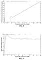
- the edge midpoint algorithm is generally a faster computational method, but it typically does not function as well on very thin samples ( Figure 8 ).
- the peak-to-peak amplitude method is also fast, but only works on very thin samples ( Figure 9 ).
- the model fitting and deconvolution algorithms typically work with all samples, and provides higher precision (Table 1), but are slower to compute.
- the midpoint of a pulse's edges are determined and offset so that they are at 0V.
- a number of points around the 0V midpoint are selected for analysis ( Figure 10 ).
- a linear fit of the data is performed for points around this midpoint ( Figure 10 ).
- the resulting linear fit equation is solved for its intercept and that value is the time assigned to that peak.
- a linear fit of the selected points provides the most computationally simple and thus fastest method to precisely determine the edge midpoint.
- higher order fits are also possible and can provide further time precision improvements.
- a 3rd order polynomial had demonstrated improved fitting precision.
- Other non-linear or higher order fits are possible.
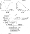
- FIG. 12 A flowchart detailing the method 34 for a midpoint determination is shown in Figure 12 .
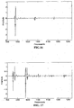
- Example peak shapes are highlighted in Figure 13 , where the two standard cases for multiple peak find. If the ratio of Vmin/Vmax is too large, the peak is assumed to be a bipolar case as given below. If the ratio of Vmin/Vmin2 (or Vmax/Vmax2) is too large, the peak is marked as irregular (type 3).
- Figure 14 provides the two non-standard 'bipolar' cases for multiple peak find. The above results confirm we are able to resolve and quantify multiple peaks and edges per peak using the edge midpoint detection algorithm.
- the method 34 first acquires a waveform as shown in step 36.
- step 38 a determination is made if a maximum voltage is greater than the absolute value of the minimum of the waveform. If step 38 is true, then a determination is made in step 40 if the minimum occurred before the maximum. Thereafter, in step 42, a minimum is found by stepping back from the maximum. The method 34 then continues to step 48 which will be described in greater detail in the paragraphs that follow.
- step 38 determines whether step 38 is false. If step 38 is false, a determination is made in step 44 if the maximum occurred before the minimum. If step 44 is false, the method continues to step 48 which will be described in greater detail later. Otherwise, the method continues to step 46 where the maximum is determined by stepping back from the minimum.
- step 48 a linear fit is accomplished by using a linear regression of a subset of data points between a minimum value and a maximum value of the waveform.
- step 50 a pulse time is determined by when the linear regression line is at a midpoint of maximum and minimum voltages.
- This model fitting method uses the edge midpoint method as a starting point for fitting a model waveform.
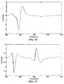
- the model waveform is a single THz pulse ( Figure 16 , Figure 18 ), collected as much as possible using the same conditions as the sample waveform ( Figure 17 , Figure 19 ).
- the edge midpoint is used to generate a starting point for the model fitting, which then uses a simplex optimization method to evaluate a series of trial waveforms with varying timing and amplitude and converge on the best solution parameters.
- FIG. 20 For initial testing, two copies of the model waveform are used to fit the front and back of a 0.5 mm (0.02") thick plastic shim.
- waveform 52 is sample waveform
- waveform 54 is trial waveform, wherein the starting point of trial fit of model waveform to sample waveform using 256 points.
- Figure 21 illustrates the final result after method optimization, wherein waveform 56 is sample waveform, and waveform 58 is trial waveform.
- the optimization varies the timing of the two copies and overall scaling of the waveform.
- W trial and W ref are the time domain trial and reference waveforms
- C is a scaling factor
- ⁇ (v) is the phase shift from the model peak to the first sample peak
- ⁇ (v) is the phase shift from the first sample peak to the second sample peak.
- Each waveform itself is 99 averages.
- the time is measured on a slow Personal Computer.
- Method Standard deviation (mean 8 to 8.15ps) Time required Zero crossing method 1.62fs 0.046 sec Peak fitting, 256 points 0.91 fs 0.21 sec Peak fitting, 512 points 0.90fs 0.33 sec Peak fitting, entire waveform 0.91 fs 2.80 sec
- THz measurements can be considered as the convolution of the inherent instrument response (due to photoconductive material properties, laser pulse shape, transmitter and receiver antenna geometries, etc.) with the surface(s) of the sample. If the instrument response can be determined separately, for instance by using a reference surface, the THz measurement can be deconvolved to extract the sample surface data alone. Deconvolution has been reported in the past for THz 3D reconstruction. The unique element here is the application of deconvolution to thickness measurements. Deconvolution prior to model fitting improves the accuracy of the results.
- the acquired terahertz waveform y(t) is the convolution of the reference waveform or instrument response h(t), with the Fresnel reflections from the actual object x(t).
- the object may have multiple layers of differing refractive index, absorbance and thickness.
- (x) and ( t ) represent the forward and inverse Fourier transforms respectively.
- Deconvolution is the inverse operation of reconstructing an unknown object given the acquired THz waveform and a THz reference waveform.
- the division produces very noisy results because the THz measurement is oversampled to prevent aliasing.
- the oversampled measurement has zero or minimal SNR over part of the frequency range, and in this frequency range the result of the division is to amplify the noise.
- the solution is to filter the measurement.
- One method is a simple bandpass filter. However, this needs to be adjusted for the bandwidth of each THz system configuration, and may create impulse response artifacts.
- An alternate filter R( ⁇ ) is the Tikhonov filter, a simple, gradual filter to eliminate low-SNR parts of the spectrum: R ⁇ ⁇ 1 1 + ⁇ F h t 2
- Figure 23 shows a sample THz measurement and reference measurement.
- the line 58 is a reflected THz measurement from a painted panel.
- the line 60 is the instrument response, measured separately.
- Figure 24 shows the Fourier transforms of the measurements.
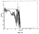
- Figure 25 and Figure 26 show the result of the division in the Fourier domain.
- the signal has already been bandpassed to limit it to 2.2THz.
- the increasing variability of the signal at higher frequencies e.g. around 0.5THz vs. around 2THz
- the results are shown of applying the Tikhonov filter to the result of Figure 25 causes a reweighting of the data toward the frequencies with greater SNR.
- the line 62 is the result of dividing the reference pulse by itself and applying the same filtering.
- Figure 27 shows the completed deconvolution.
- the peaks are narrower and symmetric, which makes them more discernable than the original waveforms.
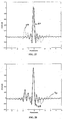
- Line 64 is the inverse Fourier transform of the data in Figure 26 , which is the completed deconvolution of the data in Figure 23 .
- Line 66 is the deconvolution of the reference pulse, which can be fit to the sample pulse for increased accuracy.
- the deconvolution method is followed by a model fitting. As described above, the timing and amplitude of the fitting function is varied using a simplex multidimensional search technique.
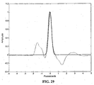
- FIG. 29 is the result of convolving Figure 27 with a Gaussian.
- the Gaussian has relatively compact support and minimizes ripple, although the FWHM of the peaks is slightly increased.
- Figure 30 is the model fitting of Figure 29 .
- a major advantage of the deconvolution / fitting method is the extension to thinner samples the expected linear behavior of the fit of the delta transit time between reflections off the front and rear surfaces of samples to the thickness of the sample ( Figure 22 ).
- time-domain Terahertz waveform pulses are the pulse's position in time and amplitude. It is well understood that instrumental or environmental conditions (e.g., noise, drift) effect the measurement, in this case decreasing the precision of the peak time position or amplitude measurement.
- a system internal reference could both confirm proper system operation, and, if necessary, provide data for corrections (e.g., amplitude scaling or time calibration) to the sample waveform results.
- any refractive index interface will generate a reflection of a THz pulse.
- the proposed invention and implementation here is to install an internal calibration etalon 72 in the sensor head that would provide reflection signals to be used for system and measurement calibration. Note that, for a sensor with this internal calibration etalon and a single layer film type sample shown, four interfaces (etalon front and rear surface and sample front and rear surface) are present. Thus four reflection peaks (designated by the reference numerals 74, 76, 78 and 80 in Figure 33 are expected. A TD-THz waveform of such an experimental configuration is shown in Figure 22 . The expected 4 reflection peaks are observed.
- this concept is not limited to 4 interfaces, but could be extended to any number of interfaces, for example multilayer samples or stacked samples.
- the calibration etalon would be ideally manufactured from a stable material with a low thermal expansion coefficient, low index of refraction at THz frequencies and extremely low absorption.
- High Density Polyethylene (HDPE) is a reasonable target material.
- Low resistivity Silicon or fused silica are also options.
- this calibration etalon would be to provide for a simultaneous measurement of the timing and amplitude of the etalon and the sample for each individual waveform acquisition. Changes in the instrumentation or environmental conditions would be reflected as changes in the calibration etalon peaks. The etalon would be chosen to provide a stable signal, thus changes in the etalon measurements could be used to adjust the sample measurements. Example adjustments would include scaling the sample delta time measurement or using the calibration signal amplitude information to improve the model fit algorithm. It is important to note again that this calibration / reference information would be contained within each individual TD-THz reflection waveform. The TD-THz waveform time window would have to be long enough to ensure both the calibration etalon and sample reflections occur within this window.
- the amplitude of the reflected pulses could be used to help model the reflected sample waveform pulses, especially for the peak to peak amplitude and model fitting methods.
- the thickness of the etalon would be varied to provide the best calibration precision. Ideally, the etalon would only reflect a small portion of the THz pulse, leaving the bulk of the pulse energy to pass on to the sample. If the etalon were relatively thick, then two cleanly separated reflection peaks (as seen in Figure 6 and Figure 22 ) would result. Then a measure of the delta time between the two calibration etalon peaks would be the preferred time analysis method. If the etalon were sufficiently thin, it would reflect less THz energy, which is preferred. However, in this case the individual interfaces would not be time resolved and the model fit using amplitude fit method discussed earlier would be required. Which method and algorithm provides better sample measurement precision would depend on the sample and experimental conditions (e.g., measurement rate).
- the use of a rear reflector 84 with the Internal Calibration Etalon (ICE) 82 allows improved measurement precision of other sample properties.
- An example is the absolute thickness of the sample.
- the typical method to calculate the thickness of a sample requires the value of the delta pulse transit times for the TD-THz pulse reflections off the front and rear surfaces of the sample and knowledge of the sample's refractive index. With the use of an ICE and rear reflector, higher precision thickness measurements can be made without knowledge of the sample material's refractive index.
- the delta pulse transit time value for the empty structure needs to be measured and recorded. This value is used in the calculation of the absolute sample thickness.
- Thickness T Ref ⁇ T Pk 1 ⁇ T Pk 3 + T Pk 2 ⁇ c
- T Pk times are relative to the T Pk0 time.
- the T Ref value is measured with the empty ICE / Rear Reflector structure.
- c is the known value for the speed of light. The calculation provides high precision result for the sample thickness regardless of the sample material composition.
- multipassing the THz pulse through the sample in a transmission measurement would increase the observed time-of-flight delay between an air reference and sample scan without increasing the imprecision of the timing measurement. This is desirable.
- first multipass sample chamber 86 with a sample 14 and a second multipass sample chamber 88 without a sample are shown.
- the first and second multipass sample chambers 86 and 88 each include a fully reflecting mirrors 90 and 92 and partially reflecting mirrors 94 and 96. Also shown are resulting sample waveforms 98 and 100 for the multipass sample chambers 86 and 88, respectively. If one side of the multipass sample chambers 86 and 88 were selected to be only partially reflecting, then multiple acquisitions of the transmitting THz pulse are possible within the same time-domain waveform.
- the thickness of the sample would be determined by the increase in the spacing between transmission pulses for the sample compared to air.
- the pulse delta time value for air would be a required value.
- this value would be relatively easy to measure as the delta time would be determined by the sample multipass etalon spacing.
- This spacing could be set to any appropriate distance to give clear separation between the transmission pulses. This minimum separation would be maintained for all sample thicknesses, that is the two pulse do not convolve and interfere with each other as is seen for reflection measurement of thin sample. This aspect would be quite advantageous for transmission measurements.
- the advantage of the multiple transmissions passes increasing the measured time-of-flight delay (as a multiple of the number of pass through the sample) still exists. That is the delay between the first and third transmission pulses would be four times that of an air / single pass transmission. This will translate into significantly improved precision of the delta time measurement.
- Figure 37 shows another embodiment of the multipass sample chamber 86, which shows a first transmission pulse 102, a second transmission pulse 104 and a third transmission pulse 106. If it is possible to increase the etalon such that a set pulse etalon reflections occurs with no sample in the THz beam, then the resulting waveform will simultaneously provide information of the etalon and the increase in time-of-flight for the transmission pulse through the sample. Figure 37 also illustrates the resulting waveform 108.
- the computer system 110 can include a set of instructions that can be executed to cause the computer system 110 to perform any one or more of the methods or computer based functions disclosed herein.
- Computer system 110 may operate as a standalone device or may be connected, e.g., using a network, to other computer systems or peripheral devices.
- the computer system may operate in the capacity of a server or as a client user computer in a server-client user network environment, or as a peer computer system in a peer-to-peer (or distributed) network environment.
- the computer system 110 can also be implemented as or incorporated into various devices, such as a personal computer (PC), a tablet PC, a set-top box (STB), a personal digital assistant (PDA), a mobile device, a palmtop computer, a laptop computer, a desktop computer, a communications device, a wireless telephone, a land-line telephone, a control system, a camera, a scanner, a facsimile machine, a printer, a pager, a personal trusted device, a web appliance, a network router, switch or bridge, or any other machine capable of executing a set of instructions (sequential or otherwise) that specify actions to be taken by that machine.
- the computer system 110 can be implemented using electronic devices that provide voice, video or data communication.
- the term "system” shall also be taken to include any collection of systems or sub-systems that individually or jointly execute a set, or multiple sets, of instructions to perform one or more computer functions.
- the computer system 110 may include a processor 112, e.g., a central processing unit (CPU), a graphics processing unit (GPU), or both. Moreover, the computer system 110 can include a main memory 114 and a static memory 116 that can communicate with each other via a bus 118. As shown, the computer system 110 may further include a video display unit 120, such as a liquid crystal display (LCD), an organic light emitting diode (OLED), a flat panel display, a solid state display, or a cathode ray tube (CRT). Additionally, the computer system 110 may include an input device 122, such as a keyboard, and a cursor control device 124, such as a mouse. The computer system 110 can also include a disk drive unit 126, a signal generation device 128, such as a speaker or remote control, and a network interface device 130.
- a processor 112 e.g., a central processing unit (CPU), a graphics processing unit (GPU), or both.
- the computer system 110
- the disk drive unit 126 may include a computer-readable medium 132 in which one or more sets of instructions 134, e.g. software, can be embedded. Further, the instructions 134 may embody one or more of the methods or logic as described herein. In a particular embodiment, the instructions 134 may reside completely, or at least partially, within the main memory 114, the static memory 116, and/or within the processor 112 during execution by the computer system 110. The main memory 114 and the processor 82 also may include computer-readable media.
- dedicated hardware implementations such as application specific integrated circuits, programmable logic arrays and other hardware devices, can be constructed to implement one or more of the methods described herein.
- Applications that may include the apparatus and systems of various embodiments can broadly include a variety of electronic and computer systems.
- One or more embodiments described herein may implement functions using two or more specific interconnected hardware modules or devices with related control and data signals that can be communicated between and through the modules, or as portions of an application-specific integrated circuit. Accordingly, the present system encompasses software, firmware, and hardware implementations.
- the methods described herein may be implemented by software programs executable by a computer system.
- implementations can include distributed processing, component/object distributed processing, and parallel processing.
- virtual computer system processing can be constructed to implement one or more of the methods or functionality as described herein.
- the present disclosure contemplates a computer-readable medium that includes instructions 134 or receives and executes instructions 134 responsive to a propagated signal, so that a device connected to a network 136 can communicate voice, video or data over the network 136. Further, the instructions 134 may be transmitted or received over the network 136 via the network interface device 130.
- While the computer-readable medium is shown to be a single medium, the term “computer-readable medium” includes a single medium or multiple media, such as a centralized or distributed database, and/or associated caches and servers that store one or more sets of instructions.
- the term “computer-readable medium” shall also include any medium that is capable of storing, encoding or carrying a set of instructions for execution by a processor that cause a computer system to perform any one or more of the methods or operations disclosed herein.
- the computer-readable medium can include a solid-state memory such as a memory card or other package that houses one or more non-volatile read-only memories. Further, the computer-readable medium can be a random access memory or other volatile re-writable memory. Additionally, the computer-readable medium can include a magneto-optical or optical medium, such as a disk or tapes or other storage device to capture carrier wave signals such as a signal communicated over a transmission medium. A digital file attachment to an e-mail or other self-contained information archive or set of archives may be considered a distribution medium that is equivalent to a tangible storage medium. Accordingly, the disclosure is considered to include any one or more of a computer-readable medium or a distribution medium and other equivalents and successor media, in which data or instructions may be stored.
Landscapes
- Physics & Mathematics (AREA)
- General Physics & Mathematics (AREA)
- Spectroscopy & Molecular Physics (AREA)
- Health & Medical Sciences (AREA)
- Biochemistry (AREA)
- Immunology (AREA)
- Radar, Positioning & Navigation (AREA)
- Engineering & Computer Science (AREA)
- Pathology (AREA)
- Life Sciences & Earth Sciences (AREA)
- Chemical & Material Sciences (AREA)
- Analytical Chemistry (AREA)
- Electromagnetism (AREA)
- General Health & Medical Sciences (AREA)
- Remote Sensing (AREA)
- Toxicology (AREA)
- Investigating Or Analysing Materials By Optical Means (AREA)
- Length Measuring Devices By Optical Means (AREA)
Description
- The present invention relates to methods to measure the transit time values for pulses in time domain waveform data. Examples will be presented using Time-Domain Terahertz data to determine sample properties. Terahertz electromagnetic radiation is potentially useful in many industrial measurement applications. In TD-THz, essentially single cycle pulses (approximately 1 ps width,
Figure 1 ) of radiation are synchronously generated and detected. This synchronous method results in high fidelity measurement of the radiation's electric field strength over a waveform time window. This width of this window can vary over a wide range depending on the instrumentation used. As THz radiation pulses are very brief in time, they will contain an extremely wide band of frequencies (10 GHz up to 50 THz). - Once a TD-THz pulse has interacted with a sample, a number of useful measurements can be extracted from acquired time-domain data. Possible measurements include, but are not limited to, sample mass, thickness, density, refractive index, density and surface variations, and spectroscopy (e.g. moisture content, polymorph identification).
-
Figure 2 illustrates aterahertz transmitter 10 andterahertz receiver 12. TD-THz, the changes in the THz pulses after they have interacted with material are recorded in a time-domain waveform. For example, as the pulse transmits through asample 14, the pulse's arrival at the receiver will be attenuated and delayed compared to the transmission of the same pulse through an air path (Figure 2 ). The amount of the pulse delay is determined by the material's group refractive index value and the amount of mass in the sample beam. The attenuation of the pulse is also dependent on material's refractive index (Fresnel reflection loss), the scattering of radiation with the sample and the attenuation of the pulse's frequencies by the material. - In the top schematic, a THz pulse travels through air with minimum timeof-flight and no loss in amplitude. The addition of essentially transparent solid materials (e.g., plastics, paper, and cloth), in the THz beam path (lower left) will result in a longer time-of-flight for the pulse. The increased time-of-flight will be proportional to the mass and index of refraction of the material. In the bottom right schematic, scattering or absorbing media (such as foam or water laden cloth) will reduce the pulse amplitude in addition to generating a time-of-flight pulse delay.
- Many measurements can be made with reflections of the TD-THz pulses off the sample (
Figure 3 ). This figure illustrates a subset of possible interactions and thus sample properties that can be measured. The consistent need for all measurements is the precision determination of the transit time value for the TD-THz pulse(s). - An example measurement would be sample thickness measurement. This measurement could be made in either transmission or reflection optical geometries. In transmission, the delay of the THz pulse by the
sample 14 can be used to measure thickness (Figure 4 ). InFigure 4 ,Line 16 represents no sample. Line 18 represents a thin sample.Line 20 represents a thick sample. This method requires determining the time position of peaks from two time-domain waveforms that were acquired at two different times (i.e., sample in and out of the beam). This method can result in offset or scaling errors if the position of either peak is shifted due to instrumental or environmental conditions. - Alternatively, THz pulses will reflect some energy at any interface (e.g., Fresnel reflection). Referring to
Figure 5 , amultipass sample chamber 21 is illustrated.Reflections using mirrors Figure 6 . The time delay between these two reflection peaks is determined by the mass and the refractive index of the material. Thus, it is possible to measure the sample's mass, thickness and/or density of a sample from a single time-domain waveform. Measurements made in this manner will exhibit reduced offset or timing slope errors. - Multipassing the THz pulses through the sample would increase the observed time delay without changing the imprecision of the pulse time measurement (as long a sufficient Signal-to-Noise is maintained). This concept is illustrated in
Figure 4 . This method would increase the overall sample thickness measurement precision. - An interesting aspect of reflection waveforms is the polarity of the waveform pulses. TD-THz measures the direct electric field, thus the polarity of the pulse does indicate the electric field polarity. In transmission measurements, the presence of a sample does not affect the pulse polarity. However, for reflection measurements, the pulse will flip polarity when reflecting off a low to high refractive index or metal interface. That is why the first pulse in the reflection waveform of
Figure 6 (air-tosample) is flipped in polarity. The strength of reflection is dependent, among other factors, on the difference in refractive index between the two materials. This information can be used to determine the delta refractive index change, including the sign of the delta, of the two materials across the interface. - Hirsch O. et al: "Techniques for cancellation of interfering multiple reflections in terahertz time-domain measurements", Microelectronics Journal 39 (2008) 841-848 describes algorithms allowing a significant reduction of the effects of multiple pulses, which originate from pulse reflections within terahertz (THz) emitters. The algorithms are based on models for the pulse propagation inside the emitter. Model parameters can be estimated from a calibration experiment using a reference signal in the absence of a sample. The parameters once estimated for a particular emitter device, can then be used to suppress the effects of multiple pulses in all measurements performed with the same emitter. The application of this method is demonstrated in the investigation of a disc sample and in the investigation of a paint layer.
-
-
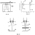
Figure 1 illustrates a Time-Domain Terahertz (TD-THz) Waveform; -
Figure 2 illustrates a THz pulse interactions with materials; -
Figure 3 illustrates a Example Reflection Interactions of TD-THz pulses; -
Figure 4 illustrates a transmission measurement of air and various thickness samples; -
Figure 5 illustrates a multipass sample chamber; -
Figure 6 illustrates a reflection TD-THz waveform from a sample; -
Figure 7 illustrates a simulated example of a TD-THz pulse reflected from various material thicknesses; -
Figure 8 illustrates a plot of the edge midpoint algorithm applied to various sample thicknesses; -
Figure 9 illustrates a plot of the peak-to-peak reflected waveform amplitude versus sample thickness; -
Figure 10 illustrates a pulse edge for midpoint determination; -
Figure 11 illustrates a linear fit of selected edge midpoint; -
Figure 12 illustrates a Flowchart for midpoint determination; -
Figure 13 illustrates two standard cases for multiple peak find; -
Figure 14 illustrates two non-standard 'bipolar' cases for multiple peak find; -
Figure 15 illustrates a case wherein the first peak is noted as bipolar and the second as a standard type; -
Figure 16 illustrates a model waveform; -
Figure 17 illustrates a sample waveform, wherein the first two peaks are the plastic shim, and the second two peaks are a silicon reference etalon; -
Figure 18 illustrates a zoomed view of model waveform peak; -
Figure 19 illustrates a zoomed view of sample waveform peaks; -
Figure 20 illustrates a starting point of trial fit of model waveform to sample waveform using 256 points; -
Figure 21 illustrates a final result after method optimization; -
Figure 22 illustrates a plastic shim thickness measurement results; -
Figure 23 illustrates sample data for deconvolution method; -
Figure 24 illustrates a Fourier transform of the data inFigure 23 ; -
Figure 25 illustrates a frequency domain result of dividing the sample by the reference; -
Figure 26 illustrates a Tikhonov filter to the result ofFigure 25 causes a reweighting of the data toward the frequencies with greater signal to noise ratio; -
Figure 27 illustrates an inverse Fourier transform of the data inFigure 26 , which is the completed deconvolution of the data inFigure 23 ; -
Figure 28 illustrates a model fitting applied to a deconvolution result; -
Figure 29 illustrates a result of convolvingFigure 27 with a Gaussian; -
Figure 30 illustrates a model fitting ofFigure 29 ; -
Figure 31 illustrates a model fitting ofFigure 30 including reflections; -
Figure 32 illustrates a sensor with Internal Calibration Etalon; -
Figure 33 illustrates a Reflection waveform from Internal Calibration Etalon Sensor and single layer sample; -
Figure 34 illustrates a ICE / Rear Reflector Structure, wherein the left most figure is an empty structure, while the right most figure is the structure with a sample; -
Figure 35 illustrates a TD-THz waveform for sample in Internal Calibration Etalon/ Rear Reflector structure; -
Figure 36 illustrates a sample multipass etalon; -
Figure 37 illustrates a multipass sample etalon chamber with a simultaneous reference air path; and -
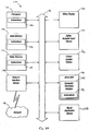
Figure 38 is a block diagram of a general purpose computer embodying the principles of the present invention. - In order to make a number of different sample property measurements, the transit time of the TD-THz pulse(s) needs to be precisely determined. This can be accomplished with multiple methods. Three algorithms for rapid, high precision pulse time value, using TD-THz pulses as example data, are presented; edge midpoint method, model fitting method, and a deconvolution with fitting method. Guidelines for determining the best algorithm are described below.
- The selection of algorithm depends on multiple factors;
Figure 7 helps illustrate this point. The waveform 26 simulates a 10ps delay between the front and back reflections, equivalent to 3mm of n=1.5 material. Thewaveform 28 is 2ps (0.6mm),waveform 30 is 0.02ps (60 microns), andwaveform 32 is 0.005ps (15 microns). The edge midpoint algorithm is generally a faster computational method, but it typically does not function as well on very thin samples (Figure 8 ). The peak-to-peak amplitude method is also fast, but only works on very thin samples (Figure 9 ). The model fitting and deconvolution algorithms typically work with all samples, and provides higher precision (Table 1), but are slower to compute. - In the edge midpoint method, the midpoint of a pulse's edges are determined and offset so that they are at 0V. A number of points around the 0V midpoint are selected for analysis (
Figure 10 ). Then a linear fit of the data is performed for points around this midpoint (Figure 10 ). The resulting linear fit equation is solved for its intercept and that value is the time assigned to that peak. This method is computationally simple and provides high precision of the peak time position, on the order of 1/75th of the waveform measurement point spacing, a significant improvement in timing precision. - A linear fit of the selected points provides the most computationally simple and thus fastest method to precisely determine the edge midpoint. However, higher order fits are also possible and can provide further time precision improvements. A 3rd order polynomial had demonstrated improved fitting precision. Other non-linear or higher order fits are possible.
- A flowchart detailing the
method 34 for a midpoint determination is shown inFigure 12 . Example peak shapes are highlighted inFigure 13 , where the two standard cases for multiple peak find. If the ratio of Vmin/Vmax is too large, the peak is assumed to be a bipolar case as given below. If the ratio of Vmin/Vmin2 (or Vmax/Vmax2) is too large, the peak is marked as irregular (type 3). -
Figure 14 provides the two non-standard 'bipolar' cases for multiple peak find. The above results confirm we are able to resolve and quantify multiple peaks and edges per peak using the edge midpoint detection algorithm. - Referring to
Figure 12 , themethod 34 first acquires a waveform as shown instep 36. Instep 38, a determination is made if a maximum voltage is greater than the absolute value of the minimum of the waveform. Ifstep 38 is true, then a determination is made instep 40 if the minimum occurred before the maximum. Thereafter, instep 42, a minimum is found by stepping back from the maximum. Themethod 34 then continues to step 48 which will be described in greater detail in the paragraphs that follow. - If
step 38 is false, a determination is made in step 44 if the maximum occurred before the minimum. If step 44 is false, the method continues to step 48 which will be described in greater detail later. Otherwise, the method continues to step 46 where the maximum is determined by stepping back from the minimum. - In
step 48, a linear fit is accomplished by using a linear regression of a subset of data points between a minimum value and a maximum value of the waveform. Finally, instep 50, a pulse time is determined by when the linear regression line is at a midpoint of maximum and minimum voltages. - This model fitting method uses the edge midpoint method as a starting point for fitting a model waveform. The model waveform is a single THz pulse (
Figure 16 ,Figure 18 ), collected as much as possible using the same conditions as the sample waveform (Figure 17 ,Figure 19 ). The edge midpoint is used to generate a starting point for the model fitting, which then uses a simplex optimization method to evaluate a series of trial waveforms with varying timing and amplitude and converge on the best solution parameters. - For initial testing, two copies of the model waveform are used to fit the front and back of a 0.5 mm (0.02") thick plastic shim. In
Figure 20 ,waveform 52 is sample waveform, andwaveform 54 is trial waveform, wherein the starting point of trial fit of model waveform to sample waveform using 256 points.Figure 21 illustrates the final result after method optimization, whereinwaveform 56 is sample waveform, andwaveform 58 is trial waveform. The optimization varies the timing of the two copies and overall scaling of the waveform. The timing ΔT is varied by changing the phase of the Fourier transform,


Table 1 - Results of peak fitting 100 waveforms collected using the spinner. Each waveform itself is 99 averages. The time is measured on a slow Personal Computer. Method Standard deviation (mean 8 to 8.15ps) Time required Zero crossing method 1.62fs 0.046 sec Peak fitting, 256 points 0.91 fs 0.21 sec Peak fitting, 512 points 0.90fs 0.33 sec Peak fitting, entire waveform 0.91 fs 2.80 sec - For the deconvolution method, THz measurements can be considered as the convolution of the inherent instrument response (due to photoconductive material properties, laser pulse shape, transmitter and receiver antenna geometries, etc.) with the surface(s) of the sample. If the instrument response can be determined separately, for instance by using a reference surface, the THz measurement can be deconvolved to extract the sample surface data alone. Deconvolution has been reported in the past for THz 3D reconstruction. The unique element here is the application of deconvolution to thickness measurements. Deconvolution prior to model fitting improves the accuracy of the results. The convolution of two functions is equivalent to multiplication of their Fourier transforms:


- For THz signals the acquired terahertz waveform y(t) is the convolution of the reference waveform or instrument response h(t), with the Fresnel reflections from the actual object x(t). The object may have multiple layers of differing refractive index, absorbance and thickness.(x) and
 (t) represent the forward and inverse Fourier transforms respectively.
- Deconvolution is the inverse operation of reconstructing an unknown object given the acquired THz waveform and a THz reference waveform. The simplest method of deconvolution uses a division in the Fourier domain:

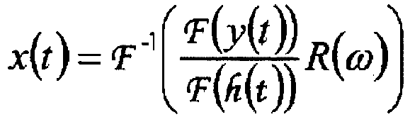
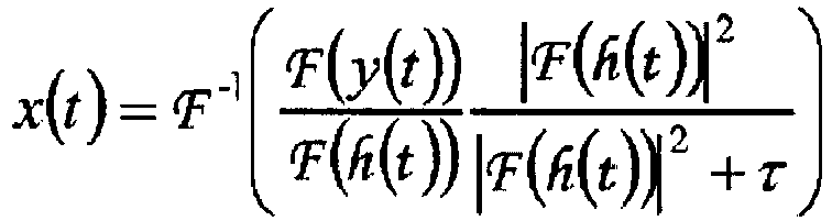
- This division produces very noisy results because the THz measurement is oversampled to prevent aliasing. The oversampled measurement has zero or minimal SNR over part of the frequency range, and in this frequency range the result of the division is to amplify the noise. The solution is to filter the measurement. One method is a simple bandpass filter. However, this needs to be adjusted for the bandwidth of each THz system configuration, and may create impulse response artifacts. An alternate filter R(ω) is the Tikhonov filter, a simple, gradual filter to eliminate low-SNR parts of the spectrum:

- This method is proposed in the context of imaging deconvolution. Doing the filtering and deconvolution simultaneously reduces the number of transforms required:

-
Figure 23 shows a sample THz measurement and reference measurement. Theline 58 is a reflected THz measurement from a painted panel. Theline 60 is the instrument response, measured separately.Figure 24 shows the Fourier transforms of the measurements.Figure 25 andFigure 26 show the result of the division in the Fourier domain. InFigure 25 , the signal has already been bandpassed to limit it to 2.2THz. However, the increasing variability of the signal at higher frequencies (e.g. around 0.5THz vs. around 2THz) is a result of the SNR variation in the broadband THz pulse. InFigure 26 , the results are shown of applying the Tikhonov filter to the result ofFigure 25 causes a reweighting of the data toward the frequencies with greater SNR. The line 62 is the result of dividing the reference pulse by itself and applying the same filtering. -
Figure 27 shows the completed deconvolution. The peaks are narrower and symmetric, which makes them more discernable than the original waveforms.Line 64 is the inverse Fourier transform of the data inFigure 26 , which is the completed deconvolution of the data inFigure 23 . Line 66 is the deconvolution of the reference pulse, which can be fit to the sample pulse for increased accuracy. The deconvolution method is followed by a model fitting. As described above, the timing and amplitude of the fitting function is varied using a simplex multidimensional search technique. - In
Figure 28 , model fitting applied to the deconvolution result. The line 68 is the result of fitting 3 copies of the reference pulse to the sample pulse.Line 70 is the residual error. - A further refinement is to convolve the deconvolved result with a smooth, compact function such as a Gaussian, as shown in
Figure 29 andFigure 30 .Figure 29 is the result of convolvingFigure 27 with a Gaussian. The Gaussian has relatively compact support and minimizes ripple, although the FWHM of the peaks is slightly increased.Figure 30 is the model fitting ofFigure 29 . - An additional refinement is to use known or assumed refractive index values for the layer materials to calculate the internal reflections within the sample as shown in
Figure 31 . The round dots indicate the amplitude and timing of the main reflections, and the stars indicate multiple bounces of the terahertz pulse between paint layers. The dotted line again indicates the residual error. - A major advantage of the deconvolution / fitting method is the extension to thinner samples the expected linear behavior of the fit of the delta transit time between reflections off the front and rear surfaces of samples to the thickness of the sample (
Figure 22 ). - As discussed, the primary measurement characteristics of time-domain Terahertz waveform pulses are the pulse's position in time and amplitude. It is well understood that instrumental or environmental conditions (e.g., noise, drift) effect the measurement, in this case decreasing the precision of the peak time position or amplitude measurement. A system internal reference could both confirm proper system operation, and, if necessary, provide data for corrections (e.g., amplitude scaling or time calibration) to the sample waveform results.
- As previously noted, any refractive index interface will generate a reflection of a THz pulse. As shown in
Figure 32 , the proposed invention and implementation here is to install an internal calibration etalon 72 in the sensor head that would provide reflection signals to be used for system and measurement calibration. Note that, for a sensor with this internal calibration etalon and a single layer film type sample shown, four interfaces (etalon front and rear surface and sample front and rear surface) are present. Thus four reflection peaks (designated by thereference numerals Figure 33 are expected. A TD-THz waveform of such an experimental configuration is shown inFigure 22 . The expected 4 reflection peaks are observed. - Also note that this concept is not limited to 4 interfaces, but could be extended to any number of interfaces, for example multilayer samples or stacked samples.
- The calibration etalon would be ideally manufactured from a stable material with a low thermal expansion coefficient, low index of refraction at THz frequencies and extremely low absorption. High Density Polyethylene (HDPE) is a reasonable target material. Low resistivity Silicon or fused silica are also options.
- The purpose of this calibration etalon would be to provide for a simultaneous measurement of the timing and amplitude of the etalon and the sample for each individual waveform acquisition. Changes in the instrumentation or environmental conditions would be reflected as changes in the calibration etalon peaks. The etalon would be chosen to provide a stable signal, thus changes in the etalon measurements could be used to adjust the sample measurements. Example adjustments would include scaling the sample delta time measurement or using the calibration signal amplitude information to improve the model fit algorithm. It is important to note again that this calibration / reference information would be contained within each individual TD-THz reflection waveform. The TD-THz waveform time window would have to be long enough to ensure both the calibration etalon and sample reflections occur within this window. The previously discussed pulse time position methods and algorithms would be critical to provide sufficient precision to allow this calibration standard to be useful. In addition, the amplitude of the reflected pulses could be used to help model the reflected sample waveform pulses, especially for the peak to peak amplitude and model fitting methods.
- The thickness of the etalon would be varied to provide the best calibration precision. Ideally, the etalon would only reflect a small portion of the THz pulse, leaving the bulk of the pulse energy to pass on to the sample. If the etalon were relatively thick, then two cleanly separated reflection peaks (as seen in
Figure 6 andFigure 22 ) would result. Then a measure of the delta time between the two calibration etalon peaks would be the preferred time analysis method. If the etalon were sufficiently thin, it would reflect less THz energy, which is preferred. However, in this case the individual interfaces would not be time resolved and the model fit using amplitude fit method discussed earlier would be required. Which method and algorithm provides better sample measurement precision would depend on the sample and experimental conditions (e.g., measurement rate). - As shown in
Figure 34 , according to the invention, the use of arear reflector 84 with the Internal Calibration Etalon (ICE) 82 allows improved measurement precision of other sample properties. An example is the absolute thickness of the sample. The typical method to calculate the thickness of a sample requires the value of the delta pulse transit times for the TD-THz pulse reflections off the front and rear surfaces of the sample and knowledge of the sample's refractive index. With the use of an ICE and rear reflector, higher precision thickness measurements can be made without knowledge of the sample material's refractive index. - For this method, the delta pulse transit time value for the empty structure needs to be measured and recorded. This value is used in the calculation of the absolute sample thickness.
- Once the sample is inserted in the structure, at least four pulses are observed (
Figure 35 ). Using the high precision methods discussed above, the transit times (Tpk#) for all the pulses needs to be found. - With these high precision values, the absolute thickness of the sample can be calculated according to the following formula:

- All TPk times are relative to the TPk0 time. The TRef value is measured with the empty ICE / Rear Reflector structure. c is the known value for the speed of light. The calculation provides high precision result for the sample thickness regardless of the sample material composition.
- As illustrated in
Figure 4 , multipassing the THz pulse through the sample in a transmission measurement would increase the observed time-of-flight delay between an air reference and sample scan without increasing the imprecision of the timing measurement. This is desirable. - However, an undesirable aspect of transmission measurements is changes in the air reference scan (e.g., drift) or in the THz transmitter / receiver spacing (e.g., mechanical motion) are in general indistinguishable from changes in the sample. The follow system and method addresses this issue.
- Referring to
Figure 36 , a firstmultipass sample chamber 86 with asample 14 and a second multipass sample chamber 88 without a sample are shown. The first and secondmultipass sample chambers 86 and 88 each include a fully reflectingmirrors mirrors sample waveforms 98 and 100 for themultipass sample chambers 86 and 88, respectively. If one side of themultipass sample chambers 86 and 88 were selected to be only partially reflecting, then multiple acquisitions of the transmitting THz pulse are possible within the same time-domain waveform. - The thickness of the sample would be determined by the increase in the spacing between transmission pulses for the sample compared to air. Thus, the pulse delta time value for air would be a required value. However this value would be relatively easy to measure as the delta time would be determined by the sample multipass etalon spacing. This spacing could be set to any appropriate distance to give clear separation between the transmission pulses. This minimum separation would be maintained for all sample thicknesses, that is the two pulse do not convolve and interfere with each other as is seen for reflection measurement of thin sample. This aspect would be quite advantageous for transmission measurements. Additionally, the advantage of the multiple transmissions passes increasing the measured time-of-flight delay (as a multiple of the number of pass through the sample) still exists. That is the delay between the first and third transmission pulses would be four times that of an air / single pass transmission. This will translate into significantly improved precision of the delta time measurement.
- Another improvement can be realized because the mechanical stability effect on the measurement would only depend on the etalon spacing, rather than the transmitter to receiver distance. It will be easier to choose materials and construction methods for the etalon that will produce greater thermal and mechanical stability. Improvements in the sample chamber etalon stability will directly translate into improved precision of the measurement.
-
Figure 37 shows another embodiment of themultipass sample chamber 86, which shows afirst transmission pulse 102, asecond transmission pulse 104 and athird transmission pulse 106. If it is possible to increase the etalon such that a set pulse etalon reflections occurs with no sample in the THz beam, then the resulting waveform will simultaneously provide information of the etalon and the increase in time-of-flight for the transmission pulse through the sample.Figure 37 also illustrates the resultingwaveform 108. - Referring to
Figure 38 , an illustrative embodiment of a general computer system is shown and is designated 110. Thecomputer system 110 can include a set of instructions that can be executed to cause thecomputer system 110 to perform any one or more of the methods or computer based functions disclosed herein.Computer system 110 may operate as a standalone device or may be connected, e.g., using a network, to other computer systems or peripheral devices. - In a networked deployment, the computer system may operate in the capacity of a server or as a client user computer in a server-client user network environment, or as a peer computer system in a peer-to-peer (or distributed) network environment. The
computer system 110 can also be implemented as or incorporated into various devices, such as a personal computer (PC), a tablet PC, a set-top box (STB), a personal digital assistant (PDA), a mobile device, a palmtop computer, a laptop computer, a desktop computer, a communications device, a wireless telephone, a land-line telephone, a control system, a camera, a scanner, a facsimile machine, a printer, a pager, a personal trusted device, a web appliance, a network router, switch or bridge, or any other machine capable of executing a set of instructions (sequential or otherwise) that specify actions to be taken by that machine. In a particular embodiment, thecomputer system 110 can be implemented using electronic devices that provide voice, video or data communication. Further, while asingle computer system 80 is illustrated, the term "system" shall also be taken to include any collection of systems or sub-systems that individually or jointly execute a set, or multiple sets, of instructions to perform one or more computer functions. - As illustrated in
Figure 38 , thecomputer system 110 may include aprocessor 112, e.g., a central processing unit (CPU), a graphics processing unit (GPU), or both. Moreover, thecomputer system 110 can include amain memory 114 and astatic memory 116 that can communicate with each other via abus 118. As shown, thecomputer system 110 may further include avideo display unit 120, such as a liquid crystal display (LCD), an organic light emitting diode (OLED), a flat panel display, a solid state display, or a cathode ray tube (CRT). Additionally, thecomputer system 110 may include aninput device 122, such as a keyboard, and acursor control device 124, such as a mouse. Thecomputer system 110 can also include adisk drive unit 126, asignal generation device 128, such as a speaker or remote control, and anetwork interface device 130. - In a particular embodiment, as depicted in
Figure 28 , thedisk drive unit 126 may include a computer-readable medium 132 in which one or more sets ofinstructions 134, e.g. software, can be embedded. Further, theinstructions 134 may embody one or more of the methods or logic as described herein. In a particular embodiment, theinstructions 134 may reside completely, or at least partially, within themain memory 114, thestatic memory 116, and/or within theprocessor 112 during execution by thecomputer system 110. Themain memory 114 and theprocessor 82 also may include computer-readable media. - In an alternative embodiment, dedicated hardware implementations, such as application specific integrated circuits, programmable logic arrays and other hardware devices, can be constructed to implement one or more of the methods described herein. Applications that may include the apparatus and systems of various embodiments can broadly include a variety of electronic and computer systems. One or more embodiments described herein may implement functions using two or more specific interconnected hardware modules or devices with related control and data signals that can be communicated between and through the modules, or as portions of an application-specific integrated circuit. Accordingly, the present system encompasses software, firmware, and hardware implementations.
- In accordance with various embodiments of the present disclosure, the methods described herein may be implemented by software programs executable by a computer system. Further, in an exemplary, non-limited embodiment, implementations can include distributed processing, component/object distributed processing, and parallel processing. Alternatively, virtual computer system processing can be constructed to implement one or more of the methods or functionality as described herein.
- The present disclosure contemplates a computer-readable medium that includes
instructions 134 or receives and executesinstructions 134 responsive to a propagated signal, so that a device connected to anetwork 136 can communicate voice, video or data over thenetwork 136. Further, theinstructions 134 may be transmitted or received over thenetwork 136 via thenetwork interface device 130. - While the computer-readable medium is shown to be a single medium, the term "computer-readable medium" includes a single medium or multiple media, such as a centralized or distributed database, and/or associated caches and servers that store one or more sets of instructions. The term "computer-readable medium" shall also include any medium that is capable of storing, encoding or carrying a set of instructions for execution by a processor that cause a computer system to perform any one or more of the methods or operations disclosed herein.
- In a particular non-limiting, exemplary embodiment, the computer-readable medium can include a solid-state memory such as a memory card or other package that houses one or more non-volatile read-only memories. Further, the computer-readable medium can be a random access memory or other volatile re-writable memory. Additionally, the computer-readable medium can include a magneto-optical or optical medium, such as a disk or tapes or other storage device to capture carrier wave signals such as a signal communicated over a transmission medium. A digital file attachment to an e-mail or other self-contained information archive or set of archives may be considered a distribution medium that is equivalent to a tangible storage medium. Accordingly, the disclosure is considered to include any one or more of a computer-readable medium or a distribution medium and other equivalents and successor media, in which data or instructions may be stored.
- Although the present specification describes components and functions that may be implemented in particular embodiments with reference to particular standards and protocols, the invention is not limited to such standards and protocols. For example, standards for Internet and other packet switched network transmission (e.g., TCP/IP, UDP/IP, HTML, HTTP) represent examples of the state of the art. Such standards are periodically superseded by faster or more efficient equivalents having essentially the same functions. Accordingly, replacement standards and protocols having the same or similar functions as those disclosed herein are considered equivalents thereof.
- The illustrations of the embodiments described herein are intended to provide a general understanding of the structure of the various embodiments. The illustrations are not intended to serve as a complete description of all of the elements and features of apparatus and systems that utilize the structures or methods described herein. Many other embodiments may be apparent to those of skill in the art upon reviewing the disclosure. Other embodiments may be utilized and derived from the disclosure, such that structural and logical substitutions and changes may be made without departing from the scope of the disclosure. Additionally, the illustrations are merely representational and may not be drawn to scale. Certain proportions within the illustrations may be exaggerated, while other proportions may be minimized. Accordingly, the disclosure and the figures are to be regarded as illustrative rather than restrictive.
- In the Detailed Description, various features may be grouped together or described in a single embodiment for the purpose of streamlining the disclosure. This disclosure is not to be interpreted as reflecting an intention that the claimed embodiments require more features than are expressly recited in each claim. Rather, as the following claims reflect, inventive subject matter may be directed to less than all of the features of any of the disclosed embodiments. Thus, the following claims are incorporated into the Detailed Description, with each claim standing on its own as defining separately claimed subject matter.
Claims (7)
- A system for interpreting a terahertz (THz) waveform, the system comprising
a THz transmitter (10) configured to output a pulse of THz radiation;
a THz receiver (12) configured to receive at least a portion of the pulse of THz radiation;
an internal calibration etalon (82) configured to receive the pulse of THz radiation coming from the THz transmitter (10) and to reflect a small portion of the THz pulse to the THz receiver (12) and to leave the bulk of the THz pulse energy pass through, wherein the internal calibration etalon (82) comprises an etalon front surface and an etalon rear surface, the etalon front surface and the etalon rear surface being refractive index interfaces configured to generate a reflection of the THz pulse respectively;
a rear reflector (84) being arranged downstream from the internal calibration etalon (82) with respect to the propagation direction of the THz pulse, wherein the rear reflector (84) is spaced apart from the internal calibration etalon (82);
a spacing between the internal calibration etalon (82) and the rear reflector (84) for arranging a sample (14) such that the sample (14) is not in direct physical contact with the internal calibration etalon (82) and the rear reflector (84), and the sample (14) can receive the portion of the pulse of THz radiation passing through the internal calibration etalon (82);
wherein the rear reflector (84) is configured to receive the portion of the pulse of THz radiation passing through the sample (14) and to reflect the portion back to the sample in the direction of the THz receiver. - The system of claim 1, further comprising a computer system (110) configured to interpret one or more time domain THz waveforms received by the THz receiver (12), the time domain THz waveforms comprising the portion of the THz pulse reflected from the internal calibration etalon (82) to the THz receiver (12), the portion of the THz pulse reflected from the rear reflector (84), the portion of the THz pulse reflected from a first refractive index interface of the sample (14), and the portion of the THz pulse reflected from a second refractive index interface of the sample (14).
- The system of claim 2, wherein the computer system (110) comprises a processor (112) configured to execute either an edge midpoint analysis method, a deconvolution analysis method, a model fitting analysis method or a combination of the deconvolution analysis method and a model fitting analysis method for interpreting the time domain THz waveforms.
- The system of claim 3, wherein during the edge midpoint analysis method, the processor (112) is configured to:find a maximum voltage amplitude point of at least one time domain THz waveform;find the absolute value of a minimum amplitude point of the at least one time domain THz waveform;determine which of the maximum amplitude point and minimum amplitude point is greater;determine which of the maximum amplitude point and minimum amplitude point occurred first with respect to time;- when the maximum amplitude point is greater than the minimum amplitude point and the minimum amplitude point occurred first with respect to time, finding the minimum amplitude point of the at least one time domain THz waveform by stepping back with respect to time along the at least one time domain THz waveform from the maximum amplitude point;- when the minimum amplitude point is greater than the maximum amplitude point and the maximum amplitude point occurred first with respect to time, finding the maximum amplitude point of the at least one time domain THz waveform by stepping back with respect to time along the at least one time domain THz waveform from the minimum amplitude point;utilizing a linear regression of a subset of data points between the minimum amplitude point and the maximum amplitude point to calculate a best fit line between the minimum amplitude point and the maximum amplitude point; anddetermine a pulse time of the at least one time domain THz waveform when the linear regression line is at the midpoint of the minimum amplitude point and the maximum amplitude point.
- The system of claim 3, wherein during the deconvolution analysis the processor (112) is configured to deconvolve and filter at least one time domain THz waveform using a reference waveform to create a deconvolved time domain THz waveform.
- The system of claim 5, wherein the processor (112) is configured to create a deconvolved time domain THz waveform by using a reference waveform comprising a waveform reflected from a reference surface having single interference.
- The system of claim 3, wherein the model fitting method utilizes a simplex optimization method.
Applications Claiming Priority (4)
| Application Number | Priority Date | Filing Date | Title |
|---|---|---|---|
| US95919607P | 2007-07-12 | 2007-07-12 | |
| US95988307P | 2007-07-17 | 2007-07-17 | |
| US96177107P | 2007-07-24 | 2007-07-24 | |
| PCT/US2008/069935 WO2009009785A1 (en) | 2007-07-12 | 2008-07-14 | System and method to measure the transit time position(s) of pulses in a time domain data |
Publications (3)
| Publication Number | Publication Date |
|---|---|
| EP2167914A1 EP2167914A1 (en) | 2010-03-31 |
| EP2167914A4 EP2167914A4 (en) | 2010-07-28 |
| EP2167914B1 true EP2167914B1 (en) | 2016-04-27 |
Family
ID=40229108
Family Applications (1)
| Application Number | Title | Priority Date | Filing Date |
|---|---|---|---|
| EP08796176.9A Active EP2167914B1 (en) | 2007-07-12 | 2008-07-14 | System to measure the transit time position(s) of pulses in a time domain data |
Country Status (8)
| Country | Link |
|---|---|
| US (1) | US8457915B2 (en) |
| EP (1) | EP2167914B1 (en) |
| JP (2) | JP5653212B2 (en) |
| KR (1) | KR101717785B1 (en) |
| CN (2) | CN105403531B (en) |
| CA (1) | CA2692942C (en) |
| ES (1) | ES2584244T3 (en) |
| WO (1) | WO2009009785A1 (en) |
Cited By (1)
| Publication number | Priority date | Publication date | Assignee | Title |
|---|---|---|---|---|
| EP4286832A1 (en) | 2022-05-31 | 2023-12-06 | Instytut Wysokich Cisnien Polskiej Akademii Nauk | Method of measuring refractive index of liquid substance under test |
Families Citing this family (47)
| Publication number | Priority date | Publication date | Assignee | Title |
|---|---|---|---|---|
| GB0814618D0 (en) * | 2008-08-11 | 2008-09-17 | Univ Leeds | Apparatus and method for measuring absorption charateristics of samples |
| DE102009021843B4 (en) * | 2009-05-19 | 2011-02-24 | Fraunhofer-Gesellschaft zur Förderung der angewandten Forschung e.V. | Method for determining a quantity of a flowable substance added to a body to be filled |
| WO2011047016A1 (en) | 2009-10-13 | 2011-04-21 | Picometrix, Llc | System and method for detection and measurement of interfacial properties in single and multilayer objects |
| US8378304B2 (en) | 2010-08-24 | 2013-02-19 | Honeywell Asca Inc. | Continuous referencing for increasing measurement precision in time-domain spectroscopy |
| US9140542B2 (en) * | 2012-02-08 | 2015-09-22 | Honeywell Asca Inc. | Caliper coating measurement on continuous non-uniform web using THz sensor |
| KR102143540B1 (en) * | 2012-10-19 | 2020-08-11 | 피코메트릭스 엘엘씨 | Calculating material properties using reflection terahertz radiation |
| JP2014209094A (en) | 2013-03-29 | 2014-11-06 | キヤノン株式会社 | Information acquisition device and information acquisition method for acquiring information on sample using terahertz wave |
| WO2015073807A1 (en) * | 2013-11-15 | 2015-05-21 | Picometrix, Llc | System for determining at least one property of a sheet dielectric sample using terahertz radiation |
| JP6238058B2 (en) * | 2013-12-17 | 2017-11-29 | 国立研究開発法人情報通信研究機構 | Terahertz spectroscopy system |
| CN105917200B (en) * | 2013-12-17 | 2019-07-02 | 派克米瑞斯有限责任公司 | Systems for transmitting and receiving electromagnetic radiation |
| EP2899497B1 (en) * | 2014-01-28 | 2019-03-13 | ABB Schweiz AG | Sensor system and method for characterizing a wet paint layer |
| EP2899498B1 (en) * | 2014-01-28 | 2020-03-11 | ABB Schweiz AG | Sensor system and method for characterizing a coated body |
| US9182281B1 (en) | 2014-05-30 | 2015-11-10 | Honeywell Asca Inc. | Robust terahertz spectrometer configuration against scanner heads misalignment |
| US20150362428A1 (en) * | 2014-06-12 | 2015-12-17 | John F. Federici | System and method for elimination of fresnel reflection boundary effects and beam steering in pulsed terahertz computed tomography |
| JP2016075618A (en) * | 2014-10-08 | 2016-05-12 | パイオニア株式会社 | Abnormality detection apparatus, abnormality detection method, computer program, and recording medium |
| WO2016132452A1 (en) * | 2015-02-17 | 2016-08-25 | パイオニア株式会社 | Terahertz wave measurement device, terahertz wave measurement method, and computer program |
| WO2016139155A1 (en) * | 2015-03-03 | 2016-09-09 | Sikora Ag | Device and method for measuring the diameter and/or the wall thickness of a strand |
| JPWO2017085862A1 (en) * | 2015-11-20 | 2018-08-30 | パイオニア株式会社 | Measuring device, measuring method, and computer program |
| DE102016105599A1 (en) * | 2016-04-14 | 2017-10-19 | Inoex Gmbh | Terahertz measuring device for the measurement of test objects and a terahertz measuring method |
| JP6815825B2 (en) * | 2016-10-25 | 2021-01-20 | 旭化成株式会社 | Evaluation device and evaluation method |
| CN111201432B (en) * | 2017-10-13 | 2023-02-17 | Abb瑞士股份有限公司 | Method and apparatus for detecting THz beams of pulses with time-of-flight correction |
| WO2019180556A1 (en) | 2018-03-22 | 2019-09-26 | 3M Innovative Properties Company | Time-domain terahertz measurement system having a single reference surface |
| US12295102B1 (en) | 2018-03-29 | 2025-05-06 | Cirrus Logic Inc. | Far field interference cancellation for resistive-inductive-capacitive sensors |
| US12130159B2 (en) | 2018-08-22 | 2024-10-29 | Cirrus Logic Inc. | Detecting and adapting to changes in a resonant phase sensing system having a resistive-inductive-capacitive sensor |
| DE102018124175A1 (en) * | 2018-10-01 | 2020-04-02 | Sikora Ag | Method and device for controlling a production plant for plate-like or strand-like bodies |
| US10948313B2 (en) | 2019-02-26 | 2021-03-16 | Cirrus Logic, Inc. | Spread spectrum sensor scanning using resistive-inductive-capacitive sensors |
| US11536758B2 (en) | 2019-02-26 | 2022-12-27 | Cirrus Logic, Inc. | Single-capacitor inductive sense systems |
| DE102019109340A1 (en) * | 2019-04-09 | 2020-10-15 | CiTEX Holding GmbH | THz measuring method and THz measuring device for detecting a flow of matter |
| JP2019203905A (en) * | 2019-09-04 | 2019-11-28 | パイオニア株式会社 | Measuring device, measuring method, and computer program |
| US12463643B2 (en) | 2019-11-19 | 2025-11-04 | Cirrus Logic Inc. | Baseline calculation for sensor system |
| DE102020113306A1 (en) * | 2020-05-15 | 2021-11-18 | Helmut Fischer GmbH Institut für Elektronik und Messtechnik | Device for transmitting and / or receiving terahertz radiation and control device therefor |
| CN111784573A (en) * | 2020-05-21 | 2020-10-16 | 昆明理工大学 | A passive terahertz image super-resolution reconstruction method based on transfer learning |
| US11868540B2 (en) * | 2020-06-25 | 2024-01-09 | Cirrus Logic Inc. | Determination of resonant frequency and quality factor for a sensor system |
| US11835410B2 (en) | 2020-06-25 | 2023-12-05 | Cirrus Logic Inc. | Determination of resonant frequency and quality factor for a sensor system |
| DE102020120547A1 (en) | 2020-08-04 | 2022-02-10 | CiTEX Holding GmbH | THz measurement method and THz measurement device for measuring a measurement object |
| US11808669B2 (en) | 2021-03-29 | 2023-11-07 | Cirrus Logic Inc. | Gain and mismatch calibration for a phase detector used in an inductive sensor |
| US11821761B2 (en) | 2021-03-29 | 2023-11-21 | Cirrus Logic Inc. | Maximizing dynamic range in resonant sensing |
| CN113821420B (en) * | 2021-08-24 | 2024-07-09 | 运达能源科技集团股份有限公司 | Performance comparison and data conversion method for CMS system of wind turbine generator |
| CN113960555B (en) * | 2021-10-19 | 2024-06-07 | 北京环境特性研究所 | Target terahertz time-domain echo processing method, device, equipment and storage medium |
| US11979115B2 (en) | 2021-11-30 | 2024-05-07 | Cirrus Logic Inc. | Modulator feedforward compensation |
| US11854738B2 (en) | 2021-12-02 | 2023-12-26 | Cirrus Logic Inc. | Slew control for variable load pulse-width modulation driver and load sensing |
| CN114964014B (en) * | 2022-05-23 | 2024-07-23 | 天津大学四川创新研究院 | Multilayer film thickness measurement method based on terahertz and readable storage medium |
| KR102806653B1 (en) * | 2023-01-12 | 2025-05-12 | 원광대학교산학협력단 | Apparatus for estimating stress state and method thereof |
| JP7527530B1 (en) * | 2024-02-09 | 2024-08-02 | 三菱電機株式会社 | Resin type estimation device and resin type estimation method |
| WO2026012891A1 (en) | 2024-07-08 | 2026-01-15 | Danmarks Tekniske Universitet | Correction of systematic delay errors of an optical delay device |
| CN119665837B (en) * | 2024-12-16 | 2026-01-02 | 江苏大学 | A method for detecting thin film thickness using terahertz technology |
| CN119880843A (en) * | 2025-03-28 | 2025-04-25 | 长春理工大学 | Multilayer medium optical parameter iterative extraction method and system |
Citations (1)
| Publication number | Priority date | Publication date | Assignee | Title |
|---|---|---|---|---|
| EP0762078A2 (en) * | 1995-08-28 | 1997-03-12 | Hewlett-Packard Company | System for determining the thickness and index of refraction of a film |
Family Cites Families (26)
| Publication number | Priority date | Publication date | Assignee | Title |
|---|---|---|---|---|
| US6078047A (en) * | 1997-03-14 | 2000-06-20 | Lucent Technologies Inc. | Method and apparatus for terahertz tomographic imaging |
| JP3417323B2 (en) * | 1998-02-03 | 2003-06-16 | 松下電器産業株式会社 | Etalon evaluation method, etalon evaluation device, and laser oscillator |
| GB2360842B (en) * | 2000-03-31 | 2002-06-26 | Toshiba Res Europ Ltd | An apparatus and method for investigating a sample |
| US6510329B2 (en) * | 2001-01-24 | 2003-01-21 | Datex-Ohmeda, Inc. | Detection of sensor off conditions in a pulse oximeter |
| US20030035120A1 (en) * | 2001-08-14 | 2003-02-20 | Myatt Christopher J. | Multiple-interferometer device for wavelength measuring and locking |
| EP1428011A2 (en) * | 2001-09-12 | 2004-06-16 | Teraview Limited | Imaging apparatus and method |
| EP1469298A1 (en) | 2001-12-28 | 2004-10-20 | Tochigi Nikon Corporation | Spectral measuring device |
| JP4046158B2 (en) * | 2002-06-21 | 2008-02-13 | 財団法人大阪産業振興機構 | Coating film measuring method and apparatus |
| US7129491B2 (en) * | 2002-11-13 | 2006-10-31 | Rensselaer Polytechnic Institute | Diffraction mode terahertz tomography |
| US7057250B2 (en) * | 2003-04-09 | 2006-06-06 | University Of Delaware | Terahertz frequency band wavelength selector |
| JP3950818B2 (en) * | 2003-05-29 | 2007-08-01 | アイシン精機株式会社 | Reflective terahertz spectrometer and measurement method |
| JP2005157601A (en) * | 2003-11-25 | 2005-06-16 | Canon Inc | Laminated object counting device and counting method using electromagnetic waves |
| GB2425833B (en) * | 2004-01-19 | 2007-02-21 | David Alexander Crawley | Terahertz Radiation Sensor and Imaging System |
| US7449695B2 (en) * | 2004-05-26 | 2008-11-11 | Picometrix | Terahertz imaging system for examining articles |
| GB2416204B (en) * | 2004-07-16 | 2007-03-21 | Teraview Ltd | Apparatus and method for investigating a sample |
| JP4609993B2 (en) * | 2004-12-08 | 2011-01-12 | 独立行政法人理化学研究所 | Terahertz wave generation method and apparatus |
| US20060227316A1 (en) * | 2005-04-06 | 2006-10-12 | Phillip Gatt | Three-dimensional imaging device |
| US20070090294A1 (en) * | 2005-10-24 | 2007-04-26 | The Boeing Company | Terahertz imaging non-destructive inspection systems and methods |
| US7601977B2 (en) * | 2005-12-13 | 2009-10-13 | Massachusetts Institute Of Technology | Phase-matched terahertz emitter |
| EP1876438A1 (en) * | 2006-07-05 | 2008-01-09 | Dtu | Determining concentration of a substance in aqueous solution by selfreferenced reflection THz spectroscopy |
| WO2008089342A1 (en) * | 2007-01-19 | 2008-07-24 | The General Hospital Corporation | Rotating disk reflection for fast wavelength scanning of dispersed broadband light |
| GB2465896B (en) | 2007-01-29 | 2011-12-07 | Teraview Ltd | A pharmaceutical analysis method and apparatus |
| GB0708491D0 (en) * | 2007-05-01 | 2007-06-06 | Univ Durham | Pulse reconstruction |
| JP4975001B2 (en) * | 2007-12-28 | 2012-07-11 | キヤノン株式会社 | Waveform information acquisition apparatus and waveform information acquisition method |
| JP2009210421A (en) * | 2008-03-04 | 2009-09-17 | Sony Corp | Terahertz spectrometer |
| JP5028529B2 (en) | 2008-10-14 | 2012-09-19 | 国立大学法人東北大学 | Sample analysis method |
-
2008
- 2008-07-14 WO PCT/US2008/069935 patent/WO2009009785A1/en not_active Ceased
- 2008-07-14 CN CN201510673031.8A patent/CN105403531B/en active Active
- 2008-07-14 US US12/667,986 patent/US8457915B2/en active Active
- 2008-07-14 EP EP08796176.9A patent/EP2167914B1/en active Active
- 2008-07-14 ES ES08796176.9T patent/ES2584244T3/en active Active
- 2008-07-14 JP JP2010516294A patent/JP5653212B2/en active Active
- 2008-07-14 CA CA2692942A patent/CA2692942C/en active Active
- 2008-07-14 CN CN200880106694A patent/CN101802551A/en active Pending
- 2008-07-14 KR KR1020107003043A patent/KR101717785B1/en active Active
-
2014
- 2014-08-04 JP JP2014158677A patent/JP5773512B2/en active Active
Patent Citations (1)
| Publication number | Priority date | Publication date | Assignee | Title |
|---|---|---|---|---|
| EP0762078A2 (en) * | 1995-08-28 | 1997-03-12 | Hewlett-Packard Company | System for determining the thickness and index of refraction of a film |
Cited By (1)
| Publication number | Priority date | Publication date | Assignee | Title |
|---|---|---|---|---|
| EP4286832A1 (en) | 2022-05-31 | 2023-12-06 | Instytut Wysokich Cisnien Polskiej Akademii Nauk | Method of measuring refractive index of liquid substance under test |
Also Published As
| Publication number | Publication date |
|---|---|
| JP5773512B2 (en) | 2015-09-02 |
| CN105403531A (en) | 2016-03-16 |
| ES2584244T3 (en) | 2016-09-26 |
| JP2010533300A (en) | 2010-10-21 |
| KR20100057801A (en) | 2010-06-01 |
| CA2692942C (en) | 2016-07-12 |
| JP2014238417A (en) | 2014-12-18 |
| CN105403531B (en) | 2019-05-14 |
| US8457915B2 (en) | 2013-06-04 |
| EP2167914A4 (en) | 2010-07-28 |
| KR101717785B1 (en) | 2017-03-17 |
| CN101802551A (en) | 2010-08-11 |
| EP2167914A1 (en) | 2010-03-31 |
| JP5653212B2 (en) | 2015-01-14 |
| WO2009009785A1 (en) | 2009-01-15 |
| US20100280779A1 (en) | 2010-11-04 |
| CA2692942A1 (en) | 2009-01-15 |
Similar Documents
| Publication | Publication Date | Title |
|---|---|---|
| EP2167914B1 (en) | System to measure the transit time position(s) of pulses in a time domain data | |
| EP2909573B1 (en) | System for calculation of material properties using reflection terahertz radiation and an external reference structure | |
| CN112105954B (en) | Frequency Modulated Continuous Wave (FMCW) Based System and Method for FMCW Range Estimation | |
| Withayachumnankul et al. | Fundamentals of measurement in terahertz time-domain spectroscopy | |
| Levine et al. | Model-based imaging of damage with Lamb waves via sparse reconstruction | |
| CN110506192B (en) | Thickness measuring device, thickness measuring method and thickness measuring procedure | |
| Abadi et al. | Broadband sparse-array blind deconvolution using frequency-difference beamforming | |
| EP3956689B1 (en) | Time-of-flight measurements using linear inverse function | |
| CN103189722B (en) | A continuous reference for increased measurement precision in time-domain spectroscopy | |
| US9134182B2 (en) | Measurement apparatus and method, tomography apparatus and method | |
| WO2011111385A1 (en) | Method for calibrating the time axis in time - domain terahertz wave measuring apparatus | |
| CN104422931A (en) | Ultrasonic measurement apparatus, ultrasonic imaging apparatus, and ultrasonic measurement method | |
| Prasad et al. | Real-time calibration of the AARTFAAC array for transient detection | |
| CN117813523A (en) | Frequency modulated continuous wave (FMCW) based system for estimation and compensation of nonlinearities in linear swept sources | |
| EP3605145A1 (en) | High-resolution remote processing method | |
| HK1147124A (en) | System and method to measure the transit time position(s) of pulses in a time domain data | |
| US10288487B2 (en) | Apparatus and method for MEMS resonant sensor arrays | |
| LT7083B (en) | METHOD, DEVICE AND SYSTEM OF ULTRASOUND ASSESSMENT OF PHYSIOLOGICAL REACTION OF PLANT LEAVES | |
| CN114384539B (en) | Absorption spectrum line phase shift speed measurement method based on background light synchronous difference | |
| WO2025202660A1 (en) | Apparatus for varying the path length of a beam of radiation | |
| Abdukirim et al. | Mitigation of atmospheric turbulence effects on ISAL imaging by real-time adaptive optics compensation | |
| TW202542482A (en) | Optical measurement equipment and optical measurement methods | |
| CN118961642A (en) | Insulation paper structural defect detection method, device, equipment, medium and product based on terahertz wave | |
| Schmidhammer et al. | Ultrafast THz sensing for inline monitoring and real time observation of transient phenomena | |
| Kadlec et al. | Terahertz spectroscopy with focused beams: Gouy shift correction for highly accurate refractive index retrieval |
Legal Events
| Date | Code | Title | Description |
|---|---|---|---|
| PUAI | Public reference made under article 153(3) epc to a published international application that has entered the european phase |
Free format text: ORIGINAL CODE: 0009012 |
|
| 17P | Request for examination filed |
Effective date: 20100112 |
|
| AK | Designated contracting states |
Kind code of ref document: A1 Designated state(s): AT BE BG CH CY CZ DE DK EE ES FI FR GB GR HR HU IE IS IT LI LT LU LV MC MT NL NO PL PT RO SE SI SK TR |
|
| AX | Request for extension of the european patent |
Extension state: AL BA MK RS |
|
| A4 | Supplementary search report drawn up and despatched |
Effective date: 20100630 |
|
| RIC1 | Information provided on ipc code assigned before grant |
Ipc: G01C 3/08 20060101ALI20100624BHEP Ipc: G01N 21/35 20060101AFI20100624BHEP |
|
| DAX | Request for extension of the european patent (deleted) | ||
| 17Q | First examination report despatched |
Effective date: 20110525 |
|
| GRAP | Despatch of communication of intention to grant a patent |
Free format text: ORIGINAL CODE: EPIDOSNIGR1 |
|
| INTG | Intention to grant announced |
Effective date: 20151112 |
|
| GRAS | Grant fee paid |
Free format text: ORIGINAL CODE: EPIDOSNIGR3 |
|
| GRAA | (expected) grant |
Free format text: ORIGINAL CODE: 0009210 |
|
| AK | Designated contracting states |
Kind code of ref document: B1 Designated state(s): AT BE BG CH CY CZ DE DK EE ES FI FR GB GR HR HU IE IS IT LI LT LU LV MC MT NL NO PL PT RO SE SI SK TR |
|
| REG | Reference to a national code |
Ref country code: GB Ref legal event code: FG4D |
|
| REG | Reference to a national code |
Ref country code: CH Ref legal event code: EP |
|
| REG | Reference to a national code |
Ref country code: AT Ref legal event code: REF Ref document number: 795334 Country of ref document: AT Kind code of ref document: T Effective date: 20160515 |
|
| REG | Reference to a national code |
Ref country code: IE Ref legal event code: FG4D |
|
| REG | Reference to a national code |
Ref country code: DE Ref legal event code: R096 Ref document number: 602008043889 Country of ref document: DE |
|
| REG | Reference to a national code |
Ref country code: FR Ref legal event code: PLFP Year of fee payment: 9 |
|
| REG | Reference to a national code |
Ref country code: NL Ref legal event code: FP |
|
| REG | Reference to a national code |
Ref country code: LT Ref legal event code: MG4D |
|
| REG | Reference to a national code |
Ref country code: ES Ref legal event code: FG2A Ref document number: 2584244 Country of ref document: ES Kind code of ref document: T3 Effective date: 20160926 |
|
| PG25 | Lapsed in a contracting state [announced via postgrant information from national office to epo] |
Ref country code: NO Free format text: LAPSE BECAUSE OF FAILURE TO SUBMIT A TRANSLATION OF THE DESCRIPTION OR TO PAY THE FEE WITHIN THE PRESCRIBED TIME-LIMIT Effective date: 20160727 Ref country code: PL Free format text: LAPSE BECAUSE OF FAILURE TO SUBMIT A TRANSLATION OF THE DESCRIPTION OR TO PAY THE FEE WITHIN THE PRESCRIBED TIME-LIMIT Effective date: 20160427 Ref country code: FI Free format text: LAPSE BECAUSE OF FAILURE TO SUBMIT A TRANSLATION OF THE DESCRIPTION OR TO PAY THE FEE WITHIN THE PRESCRIBED TIME-LIMIT Effective date: 20160427 Ref country code: LT Free format text: LAPSE BECAUSE OF FAILURE TO SUBMIT A TRANSLATION OF THE DESCRIPTION OR TO PAY THE FEE WITHIN THE PRESCRIBED TIME-LIMIT Effective date: 20160427 |
|
| PG25 | Lapsed in a contracting state [announced via postgrant information from national office to epo] |
Ref country code: SE Free format text: LAPSE BECAUSE OF FAILURE TO SUBMIT A TRANSLATION OF THE DESCRIPTION OR TO PAY THE FEE WITHIN THE PRESCRIBED TIME-LIMIT Effective date: 20160427 Ref country code: HR Free format text: LAPSE BECAUSE OF FAILURE TO SUBMIT A TRANSLATION OF THE DESCRIPTION OR TO PAY THE FEE WITHIN THE PRESCRIBED TIME-LIMIT Effective date: 20160427 Ref country code: LV Free format text: LAPSE BECAUSE OF FAILURE TO SUBMIT A TRANSLATION OF THE DESCRIPTION OR TO PAY THE FEE WITHIN THE PRESCRIBED TIME-LIMIT Effective date: 20160427 Ref country code: PT Free format text: LAPSE BECAUSE OF FAILURE TO SUBMIT A TRANSLATION OF THE DESCRIPTION OR TO PAY THE FEE WITHIN THE PRESCRIBED TIME-LIMIT Effective date: 20160829 Ref country code: GR Free format text: LAPSE BECAUSE OF FAILURE TO SUBMIT A TRANSLATION OF THE DESCRIPTION OR TO PAY THE FEE WITHIN THE PRESCRIBED TIME-LIMIT Effective date: 20160728 |
|
| PG25 | Lapsed in a contracting state [announced via postgrant information from national office to epo] |
Ref country code: BE Free format text: LAPSE BECAUSE OF FAILURE TO SUBMIT A TRANSLATION OF THE DESCRIPTION OR TO PAY THE FEE WITHIN THE PRESCRIBED TIME-LIMIT Effective date: 20160427 |
|
| REG | Reference to a national code |
Ref country code: DE Ref legal event code: R097 Ref document number: 602008043889 Country of ref document: DE |
|
| PG25 | Lapsed in a contracting state [announced via postgrant information from national office to epo] |
Ref country code: CZ Free format text: LAPSE BECAUSE OF FAILURE TO SUBMIT A TRANSLATION OF THE DESCRIPTION OR TO PAY THE FEE WITHIN THE PRESCRIBED TIME-LIMIT Effective date: 20160427 Ref country code: SK Free format text: LAPSE BECAUSE OF FAILURE TO SUBMIT A TRANSLATION OF THE DESCRIPTION OR TO PAY THE FEE WITHIN THE PRESCRIBED TIME-LIMIT Effective date: 20160427 Ref country code: DK Free format text: LAPSE BECAUSE OF FAILURE TO SUBMIT A TRANSLATION OF THE DESCRIPTION OR TO PAY THE FEE WITHIN THE PRESCRIBED TIME-LIMIT Effective date: 20160427 Ref country code: EE Free format text: LAPSE BECAUSE OF FAILURE TO SUBMIT A TRANSLATION OF THE DESCRIPTION OR TO PAY THE FEE WITHIN THE PRESCRIBED TIME-LIMIT Effective date: 20160427 Ref country code: RO Free format text: LAPSE BECAUSE OF FAILURE TO SUBMIT A TRANSLATION OF THE DESCRIPTION OR TO PAY THE FEE WITHIN THE PRESCRIBED TIME-LIMIT Effective date: 20160427 |
|
| REG | Reference to a national code |
Ref country code: CH Ref legal event code: PL |
|
| PLBE | No opposition filed within time limit |
Free format text: ORIGINAL CODE: 0009261 |
|
| STAA | Information on the status of an ep patent application or granted ep patent |
Free format text: STATUS: NO OPPOSITION FILED WITHIN TIME LIMIT |
|
| PG25 | Lapsed in a contracting state [announced via postgrant information from national office to epo] |
Ref country code: MC Free format text: LAPSE BECAUSE OF FAILURE TO SUBMIT A TRANSLATION OF THE DESCRIPTION OR TO PAY THE FEE WITHIN THE PRESCRIBED TIME-LIMIT Effective date: 20160427 |
|
| 26N | No opposition filed |
Effective date: 20170130 |
|
| PG25 | Lapsed in a contracting state [announced via postgrant information from national office to epo] |
Ref country code: LI Free format text: LAPSE BECAUSE OF NON-PAYMENT OF DUE FEES Effective date: 20160731 Ref country code: CH Free format text: LAPSE BECAUSE OF NON-PAYMENT OF DUE FEES Effective date: 20160731 |
|
| REG | Reference to a national code |
Ref country code: IE Ref legal event code: MM4A |
|
| PG25 | Lapsed in a contracting state [announced via postgrant information from national office to epo] |
Ref country code: SI Free format text: LAPSE BECAUSE OF FAILURE TO SUBMIT A TRANSLATION OF THE DESCRIPTION OR TO PAY THE FEE WITHIN THE PRESCRIBED TIME-LIMIT Effective date: 20160427 |
|
| REG | Reference to a national code |
Ref country code: FR Ref legal event code: PLFP Year of fee payment: 10 |
|
| PG25 | Lapsed in a contracting state [announced via postgrant information from national office to epo] |
Ref country code: IE Free format text: LAPSE BECAUSE OF NON-PAYMENT OF DUE FEES Effective date: 20160714 |
|
| PG25 | Lapsed in a contracting state [announced via postgrant information from national office to epo] |
Ref country code: LU Free format text: LAPSE BECAUSE OF NON-PAYMENT OF DUE FEES Effective date: 20160714 |
|
| REG | Reference to a national code |
Ref country code: AT Ref legal event code: UEP Ref document number: 795334 Country of ref document: AT Kind code of ref document: T Effective date: 20160427 |
|
| PG25 | Lapsed in a contracting state [announced via postgrant information from national office to epo] |
Ref country code: HU Free format text: LAPSE BECAUSE OF FAILURE TO SUBMIT A TRANSLATION OF THE DESCRIPTION OR TO PAY THE FEE WITHIN THE PRESCRIBED TIME-LIMIT; INVALID AB INITIO Effective date: 20080714 Ref country code: CY Free format text: LAPSE BECAUSE OF FAILURE TO SUBMIT A TRANSLATION OF THE DESCRIPTION OR TO PAY THE FEE WITHIN THE PRESCRIBED TIME-LIMIT Effective date: 20160427 |
|
| PG25 | Lapsed in a contracting state [announced via postgrant information from national office to epo] |
Ref country code: TR Free format text: LAPSE BECAUSE OF FAILURE TO SUBMIT A TRANSLATION OF THE DESCRIPTION OR TO PAY THE FEE WITHIN THE PRESCRIBED TIME-LIMIT Effective date: 20160427 Ref country code: MT Free format text: LAPSE BECAUSE OF NON-PAYMENT OF DUE FEES Effective date: 20160731 Ref country code: IS Free format text: LAPSE BECAUSE OF FAILURE TO SUBMIT A TRANSLATION OF THE DESCRIPTION OR TO PAY THE FEE WITHIN THE PRESCRIBED TIME-LIMIT Effective date: 20160427 |
|
| REG | Reference to a national code |
Ref country code: FR Ref legal event code: PLFP Year of fee payment: 11 |
|
| PG25 | Lapsed in a contracting state [announced via postgrant information from national office to epo] |
Ref country code: BG Free format text: LAPSE BECAUSE OF FAILURE TO SUBMIT A TRANSLATION OF THE DESCRIPTION OR TO PAY THE FEE WITHIN THE PRESCRIBED TIME-LIMIT Effective date: 20160427 |
|
| REG | Reference to a national code |
Ref country code: DE Ref legal event code: R081 Ref document number: 602008043889 Country of ref document: DE Owner name: LUNA INNOVATIONS INCORPORATED, ROANOKE, US Free format text: FORMER OWNER: PICOMETRIX, LLC, ANN ARBOR, MICH., US |
|
| REG | Reference to a national code |
Ref country code: GB Ref legal event code: 732E Free format text: REGISTERED BETWEEN 20211021 AND 20211027 |
|
| REG | Reference to a national code |
Ref country code: NL Ref legal event code: PD Owner name: LUNA INNOVATIONS INCORPORATED; US Free format text: DETAILS ASSIGNMENT: CHANGE OF OWNER(S), ASSIGNMENT; FORMER OWNER NAME: TERAMETRIX LLC Effective date: 20220119 Ref country code: NL Ref legal event code: HC Owner name: TERAMETRIX LLC; US Free format text: DETAILS ASSIGNMENT: CHANGE OF OWNER(S), CHANGE OF OWNER(S) NAME; FORMER OWNER NAME: PICOMETRIX, LLC Effective date: 20220119 |
|
| REG | Reference to a national code |
Ref country code: AT Ref legal event code: PC Ref document number: 795334 Country of ref document: AT Kind code of ref document: T Owner name: LUNA INNOVATIONS LNCORPORATED, US Effective date: 20220127 |
|
| P01 | Opt-out of the competence of the unified patent court (upc) registered |
Effective date: 20230526 |
|
| REG | Reference to a national code |
Ref country code: ES Ref legal event code: PC2A Owner name: LUNA INNOVATIONS INCORPORATED Effective date: 20241108 |
|
| PGFP | Annual fee paid to national office [announced via postgrant information from national office to epo] |
Ref country code: NL Payment date: 20250726 Year of fee payment: 18 |
|
| PGFP | Annual fee paid to national office [announced via postgrant information from national office to epo] |
Ref country code: ES Payment date: 20250801 Year of fee payment: 18 |
|
| PGFP | Annual fee paid to national office [announced via postgrant information from national office to epo] |
Ref country code: DE Payment date: 20250729 Year of fee payment: 18 |
|
| PGFP | Annual fee paid to national office [announced via postgrant information from national office to epo] |
Ref country code: IT Payment date: 20250721 Year of fee payment: 18 |
|
| PGFP | Annual fee paid to national office [announced via postgrant information from national office to epo] |
Ref country code: GB Payment date: 20250728 Year of fee payment: 18 |
|
| PGFP | Annual fee paid to national office [announced via postgrant information from national office to epo] |
Ref country code: AT Payment date: 20250702 Year of fee payment: 18 Ref country code: FR Payment date: 20250725 Year of fee payment: 18 |