EP2167792B1 - Turbolader von einem fahrzeug mit einer spezifischen dichtungsanordnung - Google Patents
Turbolader von einem fahrzeug mit einer spezifischen dichtungsanordnung Download PDFInfo
- Publication number
- EP2167792B1 EP2167792B1 EP08760810A EP08760810A EP2167792B1 EP 2167792 B1 EP2167792 B1 EP 2167792B1 EP 08760810 A EP08760810 A EP 08760810A EP 08760810 A EP08760810 A EP 08760810A EP 2167792 B1 EP2167792 B1 EP 2167792B1
- Authority
- EP
- European Patent Office
- Prior art keywords
- lubricating oil
- oil
- shaft
- gap
- housing
- Prior art date
- Legal status (The legal status is an assumption and is not a legal conclusion. Google has not performed a legal analysis and makes no representation as to the accuracy of the status listed.)
- Active
Links
Images

Classifications
-
- F—MECHANICAL ENGINEERING; LIGHTING; HEATING; WEAPONS; BLASTING
- F01—MACHINES OR ENGINES IN GENERAL; ENGINE PLANTS IN GENERAL; STEAM ENGINES
- F01D—NON-POSITIVE DISPLACEMENT MACHINES OR ENGINES, e.g. STEAM TURBINES
- F01D25/00—Component parts, details, or accessories, not provided for in, or of interest apart from, other groups
- F01D25/18—Lubricating arrangements
- F01D25/183—Sealing means
- F01D25/186—Sealing means for sliding contact bearing
-
- F—MECHANICAL ENGINEERING; LIGHTING; HEATING; WEAPONS; BLASTING
- F01—MACHINES OR ENGINES IN GENERAL; ENGINE PLANTS IN GENERAL; STEAM ENGINES
- F01D—NON-POSITIVE DISPLACEMENT MACHINES OR ENGINES, e.g. STEAM TURBINES
- F01D25/00—Component parts, details, or accessories, not provided for in, or of interest apart from, other groups
- F01D25/18—Lubricating arrangements
- F01D25/22—Lubricating arrangements using working-fluid or other gaseous fluid as lubricant
-
- F—MECHANICAL ENGINEERING; LIGHTING; HEATING; WEAPONS; BLASTING
- F16—ENGINEERING ELEMENTS AND UNITS; GENERAL MEASURES FOR PRODUCING AND MAINTAINING EFFECTIVE FUNCTIONING OF MACHINES OR INSTALLATIONS; THERMAL INSULATION IN GENERAL
- F16C—SHAFTS; FLEXIBLE SHAFTS; ELEMENTS OR CRANKSHAFT MECHANISMS; ROTARY BODIES OTHER THAN GEARING ELEMENTS; BEARINGS
- F16C33/00—Parts of bearings; Special methods for making bearings or parts thereof
- F16C33/02—Parts of sliding-contact bearings
- F16C33/04—Brasses; Bushes; Linings
- F16C33/06—Sliding surface mainly made of metal
- F16C33/10—Construction relative to lubrication
-
- F—MECHANICAL ENGINEERING; LIGHTING; HEATING; WEAPONS; BLASTING
- F16—ENGINEERING ELEMENTS AND UNITS; GENERAL MEASURES FOR PRODUCING AND MAINTAINING EFFECTIVE FUNCTIONING OF MACHINES OR INSTALLATIONS; THERMAL INSULATION IN GENERAL
- F16C—SHAFTS; FLEXIBLE SHAFTS; ELEMENTS OR CRANKSHAFT MECHANISMS; ROTARY BODIES OTHER THAN GEARING ELEMENTS; BEARINGS
- F16C33/00—Parts of bearings; Special methods for making bearings or parts thereof
- F16C33/02—Parts of sliding-contact bearings
- F16C33/04—Brasses; Bushes; Linings
- F16C33/06—Sliding surface mainly made of metal
- F16C33/10—Construction relative to lubrication
- F16C33/1025—Construction relative to lubrication with liquid, e.g. oil, as lubricant
-
- F—MECHANICAL ENGINEERING; LIGHTING; HEATING; WEAPONS; BLASTING
- F05—INDEXING SCHEMES RELATING TO ENGINES OR PUMPS IN VARIOUS SUBCLASSES OF CLASSES F01-F04
- F05D—INDEXING SCHEME FOR ASPECTS RELATING TO NON-POSITIVE-DISPLACEMENT MACHINES OR ENGINES, GAS-TURBINES OR JET-PROPULSION PLANTS
- F05D2220/00—Application
- F05D2220/40—Application in turbochargers
-
- F—MECHANICAL ENGINEERING; LIGHTING; HEATING; WEAPONS; BLASTING
- F16—ENGINEERING ELEMENTS AND UNITS; GENERAL MEASURES FOR PRODUCING AND MAINTAINING EFFECTIVE FUNCTIONING OF MACHINES OR INSTALLATIONS; THERMAL INSULATION IN GENERAL
- F16C—SHAFTS; FLEXIBLE SHAFTS; ELEMENTS OR CRANKSHAFT MECHANISMS; ROTARY BODIES OTHER THAN GEARING ELEMENTS; BEARINGS
- F16C17/00—Sliding-contact bearings for exclusively rotary movement
- F16C17/12—Sliding-contact bearings for exclusively rotary movement characterised by features not related to the direction of the load
- F16C17/18—Sliding-contact bearings for exclusively rotary movement characterised by features not related to the direction of the load with floating brasses or brushing, rotatable at a reduced speed
-
- F—MECHANICAL ENGINEERING; LIGHTING; HEATING; WEAPONS; BLASTING
- F16—ENGINEERING ELEMENTS AND UNITS; GENERAL MEASURES FOR PRODUCING AND MAINTAINING EFFECTIVE FUNCTIONING OF MACHINES OR INSTALLATIONS; THERMAL INSULATION IN GENERAL
- F16C—SHAFTS; FLEXIBLE SHAFTS; ELEMENTS OR CRANKSHAFT MECHANISMS; ROTARY BODIES OTHER THAN GEARING ELEMENTS; BEARINGS
- F16C2360/00—Engines or pumps
- F16C2360/23—Gas turbine engines
- F16C2360/24—Turbochargers
Definitions
- the invention relates to a turbocharger with a turbocharger housing, in which at least one impeller, such as a turbine wheel and / or a compressor wheel is mounted.
- Turbochargers normally have a housing in which a turbine wheel and a compressor wheel are rotatably mounted on a shaft by means of radial bearings.
- the shaft can reach revolutions of, for example, up to 300,000 rpm.
- To accommodate occurring axial forces can also be provided, for example, at least one thrust bearing.
- the bearings are lubricated by means of a corresponding lubricating oil.
- turbocharger In the turbocharger it may come to oil loss in the turbine and / or the compressor due to its oil-lubricated storage. In the case of the turbocharger, dynamic sealing takes place via piston rings, but these can not adequately prevent a transfer of lubricating oil to the turbine side or to the compressor side. Due to the latest exhaust technology, a transfer, in particular on the turbine side, should be avoided if possible, since it can lead, for example, to the slagging of the soot particle filter or the catalyst, with the result that their effectiveness is massively impaired.
- turbocharger housing which is provided with an oil throttle, which at least reduces a transfer of lubricating oil to the turbine side or to the compressor side.
- the bearing has the advantage that the lubricating oil flow can be throttled by the lubricating oil throttle, so that the flow of lubricating oil to the turbine or compressor wheel can be significantly reduced or substantially prevented.
- slagging of the soot particle filter or of the catalyst can be prevented and thus its effectiveness can be maintained, in contrast to the prior art, as described above.
- the housing and the shaft form a space for accommodating a relaxation volume of lubricating oil. This has the advantage that in this room a part of the lubricating oil can be initially retained.
- the gap has a gap height which is suitable for throttling a lubricating oil flow.
- a gap height which is suitable for throttling a lubricating oil flow.
- At least one sealing element is arranged in the gap in order to reduce or substantially prevent an oil passage.
- This is also a simple and easy to manufacture design to form an oil restrictor.
- the gap can also be selected slightly larger than the variant without a seal by providing an additional seal.
- a recess in the shoulder of the shaft is provided, wherein the recess is disposed adjacent to the gap and serves to receive lubricating oil, which passes through the oil throttle. In the recess while lubricating oil can be collected and retained.
- the gap is located on the side of the shaft to which the turbine wheel and / or the compressor wheel is attached so that an oil throttle may be provided to prevent uncontrolled flow of oil to the turbine wheel or impeller.
- a drain for the lubricating oil of the bearing assembly is provided in the housing.
- the oil drain can be connected to the space in which the expansion volume collects or with the depression, which is opposite to a collecting space. These are just a few examples of where oil drainage can be provided. However, the invention is not limited thereto. Thus, the oil drain can be arranged at any point which is suitable to dissipate lubricating oil and to prevent the passage of the oil to the turbine or compressor wheel.
- an oil collecting space is arranged opposite the shoulder of the shaft. This has the advantage that lubricating oil, which is thrown off the shaft, can be absorbed in the oil sump.
- a corresponding recess in the shoulder opposite the oil collecting space is provided in the shaft.
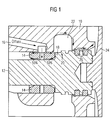
- a section of a turbocharger housing 10 according to the prior art in a sectional view is shown.
- a turbo shaft 12 is arranged, which is rotatably mounted on each side via a respective radial bearing 14.
- a lubricating oil supply 16 is provided, for example in the form of a bore through the Lubricating oil is passed to the bearings 14.
- radial bearing 14 is a raised paragraph 18 is provided with a ⁇ lschleudkante 20.
- the oil-spinning edge 20 is located opposite an oil collection chamber 22 in the housing 10 of the turbocharger. Following the ⁇ lschleuderkante 20 of paragraph 18, at the end of a turbine wheel 24 is fixed, provided with two piston rings or piston ring seals 26 for sealing.
- the lubricating oil which is supplied via the oil supply 16 to the radial bearing 14, exits axially from the storage, as with the arrows in Fig. 1 is drawn. In this case occurs in both directions of the respective bearing 14 about 50% of the lubricating oil, as with the arrows in Fig. 1 is drawn.
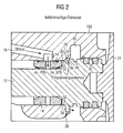
- a turbocharger housing 100 according to a first embodiment of the invention is provided, as shown in FIG Fig. 2 is shown.
- the turbocharger housing 100 initially also has, for example, two radial bearings 14 on each side of the turbo shaft 12. Via an oil flow 16 the respective bearing 14 lubricating oil is supplied. On the outside of the one radial bearing 14, an elevated shoulder 28 is formed, as in Fig. 2 is shown. This paragraph 28 may accordingly also on the other side at the other radial bearing (not shown) be provided. This applies to all embodiments according to the invention.
- the elevated shoulder 28 forms with the turbocharger housing 10 has a narrow gap 30 at its front end.
- the gap 30 is at least partially or completely circumferential and forms an oil throttle 32. This causes the main part of the lubricating oil, for example 70%, does not exit in the direction of turbine wheel but in the opposite direction, as with the arrows in Fig. 2 is drawn. Only, for example, 30% of the lubricating oil migrate to or through the gap 30.
- the information of 70% and 30% are merely exemplary.
- a recess 34 is provided to form a space 36 for receiving a relaxation volume of lubricating oil.
- a corresponding recess can also be provided in the paragraph 28.
- only the depression may be provided in the shoulder to form a space for a relaxation volume.
- a lubricating oil guide or drain 38 is provided in the turbocharger housing 10 from which the lubricating oil collected in, for example, the recess 34 can drain properly without passing to the turbine or turbine wheel 24.
- the oil collecting space 40 is provided, in which lubricating oil reaches the shoulder 28 up to this area and is thrown away from the shaft 12.
- a depression 46 is formed in the shoulder 28, in which the lubricating oil collected in the oil collecting space 40 can be received and thereby is not forwarded directly in the direction of the turbine wheel 24.
- a piston seal arrangement is provided on the shoulder at which, for example, two piston seals 42 are provided.
- FIG Fig. 3 A second embodiment of the turbocharger housing 100 according to the invention is shown in FIG Fig. 3 shown schematically and greatly simplified.
- turbocharger housing 100 In the turbocharger housing 100 is also a shaft 12 rotatably supported by radial bearings 14.
- the lubricating oil supply for supplying lubricating oil to the bearings 14 has been omitted for reasons of clarity.
- an elevated shoulder 28 is provided on the outside of the bearing 14.
- the shoulder 28 forms with its front end a gap 30 which is formed at least partially or completely circulating, wherein in the gap 30 at least one sealing element 44 is provided to form an oil throttle.
- the sealing element 44 may be a piston ring seal.
- the oil collection chamber 40 is provided, wherein opposite to the oil collection chamber 40, a corresponding recess 46 is provided in the paragraph 28.
- the recess 46 may also be formed partially or completely circulating. If a portion of the lubricating oil despite this oil restrictor 32 in this area of the paragraph 28, the lubricating oil may indeed be thrown off the shoulder 28 and collected in the oil collection chamber 40. However, the lubricating oil is returned and thereby enters the receiving space
- the depression 46 in the shoulder 28 of the shaft 12 makes it considerably more difficult for the lubricating oil to escape laterally and to penetrate via a subsequent piston ring seal 42 into the turbine region or turbine wheel 24.
- turbocharger housing 10 can also be combined with one another.
- individual features of the two embodiments may be combined with each other without departing from the scope of the claims.
- the recess 46 instead of the recess 46 or in addition to the recess 46 of the receiving space 36 and the recess 34 of the first embodiment may be provided.
- the receiving space 36 additionally in the second embodiment, optionally in front of and / or behind at least one or more seals can be provided.
- the oil throttle 32 in the form of a gap 30 without additional seal 44, according to the first embodiment can also be provided in the second embodiment.
- this shape of the oil throttle 32 of the first embodiment may be provided additionally or alternatively to the oil throttle 32 of the second embodiment.
- the oil throttle 32 by means of seal 44 of the second embodiment also be provided in the first embodiment and that alternatively or additionally.
- the present invention and the two embodiments are not limited to reducing or substantially preventing the passage of lubricating oil into the turbine.
- the turbocharger housing 10 can be provided with an oil throttle 32 on the side of the turbine and / or the compressor.
- the two embodiments according to the invention, as shown in the Fig. 2 and 3 are shown, can also be transferred to the compressor or the compressor side. This also applies to the previously described combinations of the first and second embodiments.
Landscapes
- Engineering & Computer Science (AREA)
- General Engineering & Computer Science (AREA)
- Mechanical Engineering (AREA)
- Chemical & Material Sciences (AREA)
- Oil, Petroleum & Natural Gas (AREA)
- Supercharger (AREA)
- Structures Of Non-Positive Displacement Pumps (AREA)
- Lubrication Of Internal Combustion Engines (AREA)
Description
- Die Erfindung betrifft einen Turbolader mit einem Turboladergehäuse, in welchem wenigstens ein Laufrad, wie ein Turbinenrad und/oder ein Verdichterrad gelagert ist.
- Turbolader weisen normalerweise ein Gehäuse auf, in dem ein Turbinenrad und ein Verdichterrad auf einer Welle drehbar mittels Radiallagern gelagert sind. Dabei kann die Welle Umdrehungen von beispielsweise bis zu 300.000 U/min erreichen. Um auftretende Axialkräfte aufzunehmen kann auch beispielsweise wenigstens ein Axiallager vorgesehen werden. Die Lager werden hierbei mittels eines entsprechenden Schmieröls geschmiert.
- Bei dem Turbolader kann es aufgrund seiner ölgeschmierten Lagerung zum Ölverlust in die Turbine und/oder den Verdichter kommen. Beim Turbolader erfolgt eine dynamische Abdichtung über Kolbenringe, diese können jedoch nicht geeignet einen Übertritt von Schmieröl zur Turbinenseite bzw. zur Verdichterseite hin verhindern. Aufgrund neuester Abgastechnik ist ein Übertritt, insbesondere turbinenseitig möglichst zu vermeiden, da es beispielsweise zur Verschlackung des Russpartikelfilters bzw. des Katalysators führen kann, was zur Folge hat, dass deren Wirksamkeit massiv beeinträchtigt wird.
- Demnach ist es die Aufgabe der vorliegenden Erfindung, ein Turboladergehäuse bereitzustellen, das mit einer Öldrossel versehen ist, das einen Übertritt von Schmieröl zu Turbinenseite bzw. zur Verdichterseite zumindest reduziert.
- Diese Aufgabe wird durch ein Turboladergehäuse mit den Merkmalen des Patentanspruchs 1 gelöst.
-
US 4 314 705 beschreibt die technischen Merkmale gemäß dem Oberbegriff vom Anspruch 1 - Demgemäß wird erfindungsgemäß ein Turbolader mit einem Turboladergehäuse bereitgestellt, mit:
- einer Durchtrittsöffnung für eine Welle,
- wobei die Welle drehbar mittels einer Lageranordnung in dem Gehäuse gelagert ist,
- wobei zur Schmierung der Lager Schmieröl zugeführt wird,
und - wobei ein erhöhter Absatz der Welle an der Außenseite zumindest eines Lagers vorgesehen ist, der mit dem Gehäuse einen Spalt bildet, der als Schmieröldrossel ausgebildet ist, um einen Durchtritt von Schmieröl von Seiten des Lagers zumindest zu reduzieren und wobei eine Aussparung in dem Gehäuse im Anschluss an den Spalt angeordnet ist, wobei das Gehäuse und die Welle einen Raum zur Aufnahme eines Entspannungsvolumens von Schmieröl bilden.
- Das Lager hat dabei den Vorteil, dass der Schmierölfluss durch die Schmieröldrossel gedrosselt werden kann, so dass der Fluss an Schmieröl zum Turbinenrad bzw. Verdichterrad erheblich reduziert oder im Wesentlichen ganz unterbunden werden kann. Dadurch kann eine Verschlackung des Russpartikelfilters bzw. des Katalysators verhindert und damit deren Wirksamkeit aufrechterhalten werden, im Gegensatz zum Stand der Technik, wie er oben beschrieben wurde.
- Vorteilhafte Ausgestaltungen und Weiterbildungen der Erfin-dung ergeben sich aus den Unteransprüchen sowie der Beschreibung unter Bezugnahme auf die Zeichnungen.
- Darüber hinaus bilden das Gehäuse und die Welle einen Raum zur Aufnahme eines Entspannungsvolumens an Schmieröl. Dies hat den Vorteil, dass in diesem Raum ein Teil des Schmieröls zunächst zurückgehalten werden kann.
- Gemäß einer Ausgestaltung der Erfindung weist der Spalt eine Spalthöhe auf, die geeignet ist einen Schmierölfluss zu drosseln. Ein solcher Spalt hat den Vorteil, dass er eine sehr einfache und leicht herzustellende Ausgestaltung darstellt, um eine Öldrossel bereitzustellen.
- In einer weiteren Ausgestaltung der Erfindung ist in dem Spalt wenigstens ein Dichtelement angeordnet ist, um einen Öldurchtritt zu reduzieren oder im Wesentlichen zu verhindern. Dies stellt ebenfalls eine einfache und leicht herzustellende Ausgestaltung dar, um eine Öldrossel zu bilden. Der Spalt kann dabei wahlweise durch das Vorsehen einer zusätzlichen Dichtung auch etwas größer gewählt werden als die Variante ohne Dichtung.
- In einer anderen erfindungsgemäßen Ausführungsform ist eine Vertiefung in dem Absatz der Welle vorgesehen, wobei die Vertiefung im Anschluss an den Spalt angeordnet ist und zur Aufnahme von Schmieröl dient, welches durch die Öldrossel gelangt. In der Vertiefung kann dabei Schmieröl gesammelt und zurückgehalten werden.
- In einer anderen erfindungsgemäßen Ausführungsform ist der Spalt auf der Seite der Welle angeordnet, an der das Turbinenrad und/oder das Verdichterrad befestigt ist, so dass eine Öldrossel vorgesehen werden kann, um einen unkontrollierten ölfluß zum Turbinenrad bzw. zum Verdichterrad zu verhindern. Dies hat den Vorteil, dass grundsätzlich sowohl auf der Turbinenseite wie auch auf der Verdichterseite eine solche Öldrossel angeordnet werden kann.
- In einer anderen erfindungsgemäßen Ausführungsform ist ein Abfluss für das Schmieröl der Lageranordnung in dem Gehäuse vorgesehen. Dadurch kann das Öl sehr einfach abgeführt werden. Der Ölabfluss kann dabei mit dem Raum verbunden sein, in dem sich das Entspannungsvolumen sammelt oder mit der Vertiefung, die einem Auffangraum gegenüberliegt. Dies sind jedoch nur einige Beispiele wo der Ölabfluss vorgesehen werden kann. Die Erfindung ist jedoch nicht darauf beschränkt. So kann der Ölabfluss an jeder Stelle angeordnet sein, die geeignet ist, um Schmieröl abzuführen und einen Übertritt des öls zum Turbinenrad bzw. Verdichterrad zu verhindern.
- Gemäß einer weiteren erfindungsgemäßen Ausführungsform ist ein Ölfangraum gegenüber dem Absatz der Welle angeordnet ist. Dies hat den Vorteil, dass Schmieröl, das von der Welle weggeschleudert wird, in dem Ölfangraum aufgenommen werden kann.
- In einer anderen erfindungsgemäßen Ausführungsform ist in der Welle eine entsprechende Vertiefung in dem Absatz gegenüber dem Ölfangraum vorgesehen. Dies hat den Vorteil, dass Schmieröl das in dem Ölauffangraum aufgesammelt wird zum Teil zumindest in der Vertiefung gesammelt werden kann. Dadurch kann das Schmieröl zurückgehalten werden, bevor es zu dem Turbinen- oder Verdichterrad gelangen kann.
- Die Erfindung wird nachfolgend anhand der in den schematischen Figuren der Zeichnungen angegebenen Ausführungsbeispiele näher erläutert. Es zeigen:
- Fig. 1
- einen Ausschnitt eines Turboladergehäuses gemäß dem Stand der Technik, in einer Schnittansicht;
- Fig. 2
- eine Schnittansicht eines Turboladergehäuses gemäß einer ersten Ausführungsform der Erfindung, und
- Fig. 3
- eine Schnittansicht eines Turboladergehäuses gemäß einer zweiten Ausführungsform der Erfindung.
- In allen Figuren sind gleiche bzw. funktionsgleiche Elemente und Vorrichtungen - sofern nichts anderes angegeben ist - mit denselben Bezugszeichen versehen worden.
- In
Fig. 1 ist ein Ausschnitt eines Turboladergehäuses 10 gemäß dem Stand der Technik in einer Schnittansicht gezeigt. In dem Gehäuse 10 ist eine Turbowelle 12 angeordnet, die über jeweils ein Radiallager 14 auf jeder Seite drehbar gelagert ist. Zur Schmierung der Lagerung 14 ist eine Schmierölzufuhr 16 vorgesehen, beispielsweise in Form einer Bohrung durch die Schmieröl zu den Lagern 14 geleitet wird. Auf der Außenseite des inFig. 1 gezeigten Radiallagers 14 ist ein erhöhter Absatz 18 vorgesehen mit einer Ölschleuderkante 20. Die Ölschleuderkante 20 liegt dabei einem Ölauffangraum 22 im Gehäuse 10 des Turboladers gegenüber. Im Anschluss an die Ölschleuderkante 20 ist der Absatz 18, an dessen Ende ein Turbinenrad 24 befestigt ist, mit zwei Kolbenringen bzw. Kolbenringdichtungen 26 zur Abdichtung versehen. - Im Betrieb passiert mit dem Schmieröl folgendes. Das Schmieröl das über die Ölzufuhr 16 dem Radiallager 14 zugeführt wird, tritt axial aus der Lagerung aus, wie mit den Pfeilen in
Fig. 1 eingezeichnet ist. Dabei tritt in beiden Richtungen des jeweiligen Lagers 14 ungefähr 50% des Schmieröls aus, wie mit den Pfeilen inFig. 1 eingezeichnet ist. - Das ausgetretene Schmieröl wird von der Ölschleuderkante 20 von der Turbowelle 12 weggeschleudert und in dem gegenüberliegenden Ölauffangraum 22 des Turboladergehäuses 10 aufgefangen und nach unten zu dem Absatz der Welle 12 abgeführt. Ein Ölübertritt zur Turbine bzw. zum Turbinenrad 24 ist dabei trotz der vorgesehenen Kolbenringe 26 bei ungünstigen Druckverhältnissen leicht möglich mit den bekannten Folgen, wie der Verschmutzung von Russpartikelfilter und Katalysator.
- Um diesen Schmierölübertritt zu verhindern oder zumindest einzuschränken wird ein Turboladergehäuse 100 gemäß einer ersten Ausführungsform der Erfindung bereitgestellt, wie es in
Fig. 2 dargestellt ist. - Das Turboladergehäuse 100 weist dabei zunächst ebenfalls beispielsweise zwei Radiallager 14 auf jeder Seite der Turbowelle 12 auf. Über einen Ölzufluss 16 wird dem jeweiligen Lager 14 Schmieröl zugeführt. An der Außenseite des einen Radiallagers 14 ist dabei ein erhöhter Absatz 28 ausgebildet, wie in
Fig. 2 gezeigt ist. Dieser Absatz 28 kann entsprechend auch auf der anderen Seite bei dem anderen Radiallager (nicht dargestellt) vorgesehen werden. Dies gilt für alle erfindungsgemäßen Ausführungsformen. - Der erhöhte Absatz 28 bildet dabei mit dem Turboladergehäuse 10 einen schmalen Spalt 30 aus an seinem vorderen Ende. Der Spalt 30 ist dabei zumindest teilweise oder vollständig umlaufend und bildet eine Öldrossel 32. Dies bewirkt, dass der Hauptteil des Schmieröls, beispielsweise 70%, nicht in Richtung Turbinenrad austritt sondern in die entgegengesetzte Richtung, wie mit den Pfeilen in
Fig. 2 eingezeichnet ist. Lediglich beispielsweise 30% des Schmieröls wandern zu bzw. durch den Spalt 30. Die Angaben von 70% und 30% sind dabei lediglich beispielhaft. - Im Anschluss an diesen Spalt 30 ist in dem Turboladergehäuse 100, wie in
Fig. 2 dargestellt ist, eine Aussparung 34 vorgesehen, um einen Raum 36 zu bilden zur Aufnahme eines Entspannungsvolumens von Schmieröl. Dabei kann zusätzlich auch eine entsprechende Vertiefung (nicht dargestellt) in dem Absatz 28 vorgesehen werden. Alternativ kann auch statt der Aussparung 34 nur die Vertiefung (nicht dargestellt) in dem Absatz vorgesehen werden, um einen Raum für ein Entspannungsvolumen zu bilden. - Zusätzlich ist eine Schmierölführung bzw. ein Ölablauf 38 in dem Turboladergehäuse 10 vorgesehen, aus der das Schmieröl, das beispielsweise in der Aussparung 34 gesammelt wurde, geeignet abfließen kann, ohne dabei zu der Turbine bzw. dem Turbinenrad 24 überzutreten.
- Im Anschluss an die Aussparung 34 ist der ölauffangraum 40 vorgesehen, in dem Schmieröl das bis zu diesem Bereich an dem Absatz 28 gelangt und von der Welle 12 weggeschleudert wird aufgefangen werden kann. Gegenüberliegend dem Ölauffangraum 40 ist eine Vertiefung 46 in dem Absatz 28 ausgebildet, in der das in dem Ölauffangraum 40 aufgefangene Schmieröl aufgenommen werden kann und dadurch nicht direkt in Richtung des Turbinenrads 24 weitergeleitet wird. Im Anschluss an den Ölauffangraum 40 ist eine Kolbendichtungsanordnung auf dem Absatz vorgesehen, an der beispielsweise zwei Kolbendichtungen 42 vorgesehen sind.
- Durch die gezielte Führung des Schmieröls, das aus der Lagerung 14 abfließt, hier in
Fig. 2 beispielsweise über den Öldrosselspalt 30 und die Aussparung 34 und die Führung 38 zum Ablassen des Schmieröls in dem Turboladergehäuse 100, kann effizient verhindert werden, dass große Mengen an Öl an die Kolbenringabdichtung 42 gelangen können und dabei zu der Turbine bzw. dem Turbinenrad 24 bei ungünstigen Druckverhältnissen übertreten können. - Eine zweite Ausführungsform des erfindungsgemäßen Turboladergehäuses 100 ist in
Fig. 3 schematisch und stark vereinfacht dargestellt. - In dem Turboladergehäuse 100 ist dabei ebenfalls eine Welle 12 drehbar mittels Radiallagern 14 gelagert. Die Schmierölzuführung zum Zuführen von Schmieröl zu den Lagern 14 ist dabei aus Gründen der Übersichtlichkeit weggelassen worden. Wie in der ersten Ausführungsform ist an der Außenseite des Lagers 14 ein erhöhter Absatz 28 vorgesehen. Der Absatz 28 bildet dabei mit seinem vorderen Ende einen Spalt 30, der zumindest teilweise oder vollständig umlaufen ausgebildet ist, wobei in dem Spalt 30 wenigstens ein Dichtungselement 44 vorgesehen ist, um eine Öldrossel zu bilden. Das Dichtungselement 44 kann dabei eine Kolbenringdichtung sein.
- Im Anschluss an den Spalt 30 ist der Ölauffangraum 40 vorgesehen, wobei gegenüberliegend dem Ölauffangraum 40 eine entsprechende Vertiefung 46 in dem Absatz 28 vorgesehen ist. Die Vertiefung 46 kann dabei ebenfalls teilweise oder vollständig umlaufen ausgebildet sein. Gelangt ein Teil des Schmieröls trotz der Öldrossel 32 in diesen Bereich des Absatzes 28, so kann das Schmieröl zwar von dem Absatz 28 weggeschleudert und in dem Ölauffangraum 40 aufgefangen werden. Das Schmieröl wird jedoch zurückgeführt und gelangt dabei in die dem Aufnahmeraum 40 zumindest teilweise oder vollständig gegenüberliegende Vertiefung 46 auf dem Absatz 28. Durch die Vertiefung 46 in dem Absatz 28 der Welle 12 wird es dem Schmieröl erheblich erschwert seitlich auszutreten und über eine nachfolgende Kolbenringdichtung 42 in den Turbinenbereich bzw. zum Turbinenrad 24 hin einzudringen. Eine Schmierölzuführung 16 sowie eine Schmierölabführung bzw. ein Ölablauf 38, wie beispielsweise in der ersten Ausführungsform, wurden aus Gründen der Übersichtlichkeit weggelassen.
- Obwohl die vorliegende Erfindung vorstehend anhand der bevorzugten Ausführungsbeispiele beschrieben wurde, ist sie darauf nicht beschränkt, sondern auf vielfältige Art und Weise modifizierbar. Die zuvor beschriebenen Ausführungsformen sind dabei miteinander kombinierbar, insbesondere einzelne Merkmale davon.
- Insbesondere können die vorliegenden Ausführungsformen des erfindungsgemäßen Turboladergehäuses 10 auch miteinander kombiniert werden. Insbesondere können einzelne Merkmale der beiden Ausführungsformen miteinander kombiniert werden, ohne von dem Schutzumfang der Ansprüche abzuweichen.
- So kann beispielsweise in der zweiten Ausführungsform statt der Vertiefung 46 oder zusätzlich zu der Vertiefung 46 der Aufnahmeraum 36 bzw. die Aussparung 34 der ersten Ausführungsform vorgesehen werden. Grundsätzlich ist aber auch denkbar, beispielsweise den Aufnahmeraum 36 zusätzlich in der zweiten Ausführungsform vorzusehen, wobei wahlweise davor und/oder dahinter wenigstens eine oder mehrere Dichtungen vorgesehen werden können.
- Des Weiteren kann die Öldrossel 32 in Form eines Spalts 30 ohne zusätzliche Dichtung 44, gemäß der ersten Ausführungsform auch bei der zweiten Ausführungsform vorgesehen werden. Dabei kann diese Form der Öldrossel 32 der ersten Ausführungsform zusätzlich oder alternativ zu der Öldrossel 32 der zweiten Ausführungsform vorgesehen werden. Umgekehrt kann auch die Öldrossel 32 mittels Dichtung 44 der zweiten Ausführungsform auch bei der ersten Ausführungsform vorgesehen werden und zwar alternativ oder zusätzlich.
- Außerdem kann bei beiden erfindungsgemäßen Ausführungsformen neben zwei Kolbenringdichtungen 42 am Ende vor dem jeweiligen Laufrad, wie in den
Fig. 2 und3 dargestellt ist, auch nur eine Kolbenringdichtung 42 oder mehr als zwei Kolberingdichtungen 42 vorgesehen werden. Grundsätzlich kann aber auch eine andere Dichtung angeordnet werden, die geeignet ist einen Durchtritt an Schmieröl im Wesentlichen zu verhindern oder zumindest zu unterdrücken. - Des Weiteren ist die vorliegende Erfindung und die beiden Ausführungsformen nicht darauf beschränkt, den Übertritt von Schmieröl in die Turbine zu reduzieren oder im Wesentlichen zu verhindern. Grundsätzlich kann das Tuboladergehäuse 10 auf der Seite der Turbine und/oder des Verdichters mit einer Öldrossel 32 versehen sein. Die beiden erfindungsgemäßen Ausführungsformen, wie sie in den
Fig. 2 und3 gezeigt sind, lassen sich ebenso auf den Verdichter bzw. die Verdichterseite übertragen. Dies gilt auch für die zuvor beschriebenen Kombinationen der ersten und zweiten Ausführungsform.
Claims (10)
- Turbolader mit einem Turboladergehäuse (100), mit:einer Durchtrittsöffnung für eine Welle (12),- wobei die Welle (12) drehbar mittels einer Lageranordnung (14) in dem Gehäuse (100) gelagert ist,- wobei zur Schmierung der Lager (14) Schmieröl zugeführt wird,- wobei ein erhöhter Absatz (28) der Welle (12) an der Außenseite zumindest eines Lagers (14) vorgesehen ist, der mit dem Gehäuse (100) einen Spalt (30) bildet, der als Schmieröldrossel (32) ausgebildet ist, um einen Durchtritt von Schmieröl von Seiten des Lagers (14) zumindest zu reduzieren, und- wobei eine Aussparung (34) in dem Gehäuse (10) im Anschluss an den Spalt (30) angeordnet ist dadurch gekennzeichnet, dass das Gehäuse (10) und die Welle (12) einen Raum (36) zur Aufnahme eines Entspannungsvolumens von Schmieröl bilden.
- Turbolader nach Anspruch 1,
dadurch gekennzeichnet,
dass der Spalt (30) eine Spalthöhe aufweist, die geeignet ist einen Schmierölfluss zu drosseln. - Turbolader nach wenigstens einem der Ansprüche 1 oder 2,
dadurch gekennzeichnet,
dass in dem Spalt (30) wenigstens ein Dichtelement (42, 44) angeordnet ist, um einen Öldurchtritt zu reduzieren oder im Wesentlichen zu verhindern. - Turbolader nach wenigstens einem der Ansprüche 1 bis 3,
dadurch gekennzeichnet,
dass eine Vertiefung (46) in dem Absatz (28) der Welle (12) vorgesehen ist, wobei die Vertiefung (46) im Anschluss an den Spalt (30) angeordnet ist und zur Aufnahme von Schmieröl dient, welches durch die Öldrossel (32) gelangt. - Turbolader nach wenigstens einem der Ansprüche 1 bis 4,
dadurch gekennzeichnet,
dass der Spalt (30) zumindest teilweise oder vollständig umlaufen ausgebildet ist. - Turbolader nach wenigstens einem der Ansprüche 1 bis 5,
dadurch gekennzeichnet,
dass der Spalt (30) auf der Seite der Welle (12) angeordnet ist, an der das Turbinenrad (24) und/oder das Verdichterrad befestigt ist. - Turbolader nach wenigstens einem der Ansprüche 1 bis 6,
dadurch gekennzeichnet,
dass ein Abfluss (38) für das Schmieröl der Lageranordnung (14) in dem Gehäuse (10) vorgesehen ist. - Turbolader nach wenigstens einem der Ansprüche 1 bis 7,
dadurch gekennzeichnet,
dass ein Ölfangraum (40) gegenüber dem Absatz (28) der Welle (12) angeordnet ist. - Turbolader nach Anspruch 8,
dadurch gekennzeichnet,
dass in der Welle (12) die Vertiefung (46) in dem Absatz (28) gegenüber dem Ölfangraum (40) vorgesehen ist. - Fahrzeug mit einem Turbolader nach einem der Ansprüche 1 bis 9.
Applications Claiming Priority (2)
| Application Number | Priority Date | Filing Date | Title |
|---|---|---|---|
| DE102007027869A DE102007027869B4 (de) | 2007-06-18 | 2007-06-18 | Turbolader mit einem Turboladergehäuse |
| PCT/EP2008/057251 WO2008155267A1 (de) | 2007-06-18 | 2008-06-11 | Turbolader von einem fahrzeug mit einer spezifischen dichtungsanordnung |
Publications (2)
| Publication Number | Publication Date |
|---|---|
| EP2167792A1 EP2167792A1 (de) | 2010-03-31 |
| EP2167792B1 true EP2167792B1 (de) | 2011-06-01 |
Family
ID=39744846
Family Applications (1)
| Application Number | Title | Priority Date | Filing Date |
|---|---|---|---|
| EP08760810A Active EP2167792B1 (de) | 2007-06-18 | 2008-06-11 | Turbolader von einem fahrzeug mit einer spezifischen dichtungsanordnung |
Country Status (6)
| Country | Link |
|---|---|
| US (1) | US20100192571A1 (de) |
| EP (1) | EP2167792B1 (de) |
| JP (1) | JP5355559B2 (de) |
| AT (1) | ATE511597T1 (de) |
| DE (1) | DE102007027869B4 (de) |
| WO (1) | WO2008155267A1 (de) |
Cited By (1)
| Publication number | Priority date | Publication date | Assignee | Title |
|---|---|---|---|---|
| US11131242B2 (en) | 2017-11-24 | 2021-09-28 | Brp-Rotax Gmbh & Co. Kg | Turbocharger for an internal combustion engine |
Families Citing this family (17)
| Publication number | Priority date | Publication date | Assignee | Title |
|---|---|---|---|---|
| DE102007025131A1 (de) * | 2007-05-30 | 2008-12-04 | Mahle International Gmbh | Ladeeinrichtung |
| DE102010038524B4 (de) | 2010-07-28 | 2020-08-13 | Man Energy Solutions Se | Turbomaschine |
| WO2012027184A2 (en) | 2010-08-24 | 2012-03-01 | Borgwarner Inc. | Exhaust-gas turbocharger |
| DE102012206650B4 (de) | 2012-04-23 | 2024-03-28 | Ford Global Technologies, Llc | Turboladeranordnung für einen Verbrennungsmotor |
| JP5983188B2 (ja) * | 2012-08-28 | 2016-08-31 | ダイキン工業株式会社 | ターボ圧縮機及びターボ冷凍機 |
| DE102012022647A1 (de) | 2012-11-20 | 2014-05-22 | Daimler Ag | Abgasturbolader für eine Verbrennungskraftmaschine |
| FR3007069B1 (fr) * | 2013-06-12 | 2015-07-17 | Snecma | Tourillon pour turbine haute pression, et turboreacteur incluant un tel tourillon |
| DE102014208078A1 (de) * | 2014-04-29 | 2015-10-29 | Bosch Mahle Turbo Systems Gmbh & Co. Kg | Abgasturbolader mit einem Rotor |
| WO2016031013A1 (ja) * | 2014-08-28 | 2016-03-03 | 三菱重工業株式会社 | 軸受装置、及び回転機械 |
| DE102014221880A1 (de) | 2014-10-28 | 2016-04-28 | Schaeffler Technologies AG & Co. KG | Rotorwelle eines Abgasturboladers sowie Verfahren zur Herstellung derselben |
| DE102015204563A1 (de) | 2015-03-13 | 2016-09-15 | Bayerische Motoren Werke Aktiengesellschaft | Abgasturbolader |
| DE102015204564A1 (de) | 2015-03-13 | 2016-09-15 | Bayerische Motoren Werke Aktiengesellschaft | Abgasturbolader |
| US10927759B2 (en) * | 2016-05-20 | 2021-02-23 | Ihi Corporation | Bearing structure for turbocharger and turbocharger |
| WO2020072572A1 (en) | 2018-10-04 | 2020-04-09 | Cummins Inc. | Crankshaft thrust bearing |
| WO2020079128A1 (de) * | 2018-10-18 | 2020-04-23 | Abb Turbo Systems Ag | Abgasturbolader mit verbesserter wellendichtung |
| CN109707467B (zh) * | 2018-11-30 | 2022-02-11 | 江苏理工学院 | 一种防积碳涡轮增压器 |
| FR3108064B1 (fr) * | 2020-03-10 | 2022-06-24 | Ntn Snr Roulements | Butée de suspension de véhicule automobile |
Family Cites Families (12)
| Publication number | Priority date | Publication date | Assignee | Title |
|---|---|---|---|---|
| US2953416A (en) * | 1957-09-17 | 1960-09-20 | Garrett Corp | Thrust bearing construction |
| US4268229A (en) * | 1979-04-19 | 1981-05-19 | The Garrett Corporation | Turbocharger shaft seal arrangement |
| US4314705A (en) * | 1979-05-23 | 1982-02-09 | Ishikawajima-Harima Jukogyo Kabushiki Kaisha | Oil seal device |
| JPS5612170U (de) * | 1979-07-10 | 1981-02-02 | ||
| JPS55170420U (de) * | 1979-05-23 | 1980-12-06 | ||
| JPS5613513U (de) * | 1979-07-10 | 1981-02-05 | ||
| JPS5740634U (de) * | 1980-08-19 | 1982-03-04 | ||
| DE4012361A1 (de) * | 1989-04-19 | 1990-10-25 | Aisin Seiki | Oeldichtungsvorrichtung fuer einen turbolader |
| US5890881A (en) * | 1996-11-27 | 1999-04-06 | Alliedsignal Inc. | Pressure balanced turbocharger rotating seal |
| GB0218092D0 (en) * | 2002-08-03 | 2002-09-11 | Holset Engineering Co | Turbocharger |
| DE102004055429B3 (de) * | 2004-11-17 | 2006-08-10 | Man B & W Diesel Ag | Dichtungseinrichtung für eine insbesondere im Stillstand geschmierte Lagerung einer Rotorwelle |
| EP1947373A1 (de) * | 2007-01-19 | 2008-07-23 | ABB Turbo Systems AG | Dichtungsanordnung |
-
2007
- 2007-06-18 DE DE102007027869A patent/DE102007027869B4/de not_active Withdrawn - After Issue
-
2008
- 2008-06-11 WO PCT/EP2008/057251 patent/WO2008155267A1/de not_active Ceased
- 2008-06-11 JP JP2010512639A patent/JP5355559B2/ja active Active
- 2008-06-11 US US12/664,702 patent/US20100192571A1/en not_active Abandoned
- 2008-06-11 AT AT08760810T patent/ATE511597T1/de active
- 2008-06-11 EP EP08760810A patent/EP2167792B1/de active Active
Cited By (1)
| Publication number | Priority date | Publication date | Assignee | Title |
|---|---|---|---|---|
| US11131242B2 (en) | 2017-11-24 | 2021-09-28 | Brp-Rotax Gmbh & Co. Kg | Turbocharger for an internal combustion engine |
Also Published As
| Publication number | Publication date |
|---|---|
| JP5355559B2 (ja) | 2013-11-27 |
| US20100192571A1 (en) | 2010-08-05 |
| ATE511597T1 (de) | 2011-06-15 |
| JP2010530491A (ja) | 2010-09-09 |
| DE102007027869B4 (de) | 2010-04-29 |
| WO2008155267A1 (de) | 2008-12-24 |
| DE102007027869A1 (de) | 2008-12-24 |
| EP2167792A1 (de) | 2010-03-31 |
Similar Documents
| Publication | Publication Date | Title |
|---|---|---|
| EP2167792A1 (de) | Turbolader von einem fahrzeug mit einer spezifischen dichtungsanordnung | |
| DE19641673B4 (de) | Axialgleitlager | |
| DE102014201547B4 (de) | Turbolader | |
| EP2140114B1 (de) | Axiallager insbesondere für einen turbolader | |
| EP1103706B1 (de) | Lagerkammer für ein Gasturbinen-Triebwerk | |
| EP2137382B1 (de) | Statorhitzeschild | |
| EP3011181B1 (de) | Kältemittelverdichter | |
| DE102008020067A1 (de) | Lageranordnung mit einem doppelreihigen Wälzlager, Turbolader und Verfahren zur Zuführung eines Schmiermittels zu den Wälzkörperreihen eines doppelreihigen Wälzlagers | |
| WO2012139830A1 (de) | Lagereinheit für einen turbolader | |
| DE112013003184T5 (de) | Turbolader | |
| EP3069051A1 (de) | Planetenträger mit integrierter schmierstoffversorgung | |
| DE102005015212A1 (de) | Wellendichtung | |
| DE102004045588B4 (de) | Walzkörper-Halter und Schrägkugellageranordnung, bei welcher derselbe verwendet wird | |
| DE102014217053A1 (de) | Tragkonstruktion für eine Läuferwelle sowie ein Turbolader | |
| DE69819293T2 (de) | Hydraulikdichtung | |
| DE112017001057B4 (de) | Radialgleitlager und rotationsmaschine | |
| DE102016124283A1 (de) | Hydrodynamische Kupplung | |
| DE102016222625A1 (de) | Lagerbuchse für eine Welle eines Turboladers | |
| DE2945272A1 (de) | Turbolader | |
| DE102018129826A1 (de) | Zahnradpumpe, die luft aus dem gepumpten öl entfernt | |
| WO2019214883A1 (de) | Lagereinrichtung mit einer strukturierten welle | |
| DE112017001041T5 (de) | Gleit- oder Radiallager und Drehmaschine | |
| DE102017106942A1 (de) | Hydrodynamische Kupplung | |
| DE102014212620A1 (de) | Lageraußenring für ein Radialwälzlager | |
| DE10030698A1 (de) | Verfahren zum Schmieren und Kühlen eines hydrodynamischen Gleitlagers und Vorrichtung zur Durchführung dieses Verfahrens |
Legal Events
| Date | Code | Title | Description |
|---|---|---|---|
| PUAI | Public reference made under article 153(3) epc to a published international application that has entered the european phase |
Free format text: ORIGINAL CODE: 0009012 |
|
| 17P | Request for examination filed |
Effective date: 20100118 |
|
| AK | Designated contracting states |
Kind code of ref document: A1 Designated state(s): AT BE BG CH CY CZ DE DK EE ES FI FR GB GR HR HU IE IS IT LI LT LU LV MC MT NL NO PL PT RO SE SI SK TR |
|
| AX | Request for extension of the european patent |
Extension state: AL BA MK RS |
|
| DAX | Request for extension of the european patent (deleted) | ||
| RTI1 | Title (correction) |
Free format text: VEHICLE TURBOCHARGER WITH A SPECIFIC SEAL |
|
| GRAP | Despatch of communication of intention to grant a patent |
Free format text: ORIGINAL CODE: EPIDOSNIGR1 |
|
| RTI1 | Title (correction) |
Free format text: VEHICLE TURBOCHARGER WITH A SPECIFIC SEAL |
|
| GRAS | Grant fee paid |
Free format text: ORIGINAL CODE: EPIDOSNIGR3 |
|
| GRAA | (expected) grant |
Free format text: ORIGINAL CODE: 0009210 |
|
| AK | Designated contracting states |
Kind code of ref document: B1 Designated state(s): AT BE BG CH CY CZ DE DK EE ES FI FR GB GR HR HU IE IS IT LI LT LU LV MC MT NL NO PL PT RO SE SI SK TR |
|
| REG | Reference to a national code |
Ref country code: GB Ref legal event code: FG4D Free format text: NOT ENGLISH |
|
| REG | Reference to a national code |
Ref country code: CH Ref legal event code: EP |
|
| REG | Reference to a national code |
Ref country code: IE Ref legal event code: FG4D Free format text: LANGUAGE OF EP DOCUMENT: GERMAN |
|
| REG | Reference to a national code |
Ref country code: DE Ref legal event code: R096 Ref document number: 502008003744 Country of ref document: DE Effective date: 20110714 |
|
| REG | Reference to a national code |
Ref country code: NL Ref legal event code: VDEP Effective date: 20110601 |
|
| PG25 | Lapsed in a contracting state [announced via postgrant information from national office to epo] |
Ref country code: SE Free format text: LAPSE BECAUSE OF FAILURE TO SUBMIT A TRANSLATION OF THE DESCRIPTION OR TO PAY THE FEE WITHIN THE PRESCRIBED TIME-LIMIT Effective date: 20110601 Ref country code: LT Free format text: LAPSE BECAUSE OF FAILURE TO SUBMIT A TRANSLATION OF THE DESCRIPTION OR TO PAY THE FEE WITHIN THE PRESCRIBED TIME-LIMIT Effective date: 20110601 Ref country code: HR Free format text: LAPSE BECAUSE OF FAILURE TO SUBMIT A TRANSLATION OF THE DESCRIPTION OR TO PAY THE FEE WITHIN THE PRESCRIBED TIME-LIMIT Effective date: 20110601 Ref country code: NO Free format text: LAPSE BECAUSE OF FAILURE TO SUBMIT A TRANSLATION OF THE DESCRIPTION OR TO PAY THE FEE WITHIN THE PRESCRIBED TIME-LIMIT Effective date: 20110901 |
|
| PG25 | Lapsed in a contracting state [announced via postgrant information from national office to epo] |
Ref country code: FI Free format text: LAPSE BECAUSE OF FAILURE TO SUBMIT A TRANSLATION OF THE DESCRIPTION OR TO PAY THE FEE WITHIN THE PRESCRIBED TIME-LIMIT Effective date: 20110601 Ref country code: SI Free format text: LAPSE BECAUSE OF FAILURE TO SUBMIT A TRANSLATION OF THE DESCRIPTION OR TO PAY THE FEE WITHIN THE PRESCRIBED TIME-LIMIT Effective date: 20110601 Ref country code: LV Free format text: LAPSE BECAUSE OF FAILURE TO SUBMIT A TRANSLATION OF THE DESCRIPTION OR TO PAY THE FEE WITHIN THE PRESCRIBED TIME-LIMIT Effective date: 20110601 Ref country code: GR Free format text: LAPSE BECAUSE OF FAILURE TO SUBMIT A TRANSLATION OF THE DESCRIPTION OR TO PAY THE FEE WITHIN THE PRESCRIBED TIME-LIMIT Effective date: 20110902 Ref country code: CY Free format text: LAPSE BECAUSE OF FAILURE TO SUBMIT A TRANSLATION OF THE DESCRIPTION OR TO PAY THE FEE WITHIN THE PRESCRIBED TIME-LIMIT Effective date: 20110601 Ref country code: ES Free format text: LAPSE BECAUSE OF FAILURE TO SUBMIT A TRANSLATION OF THE DESCRIPTION OR TO PAY THE FEE WITHIN THE PRESCRIBED TIME-LIMIT Effective date: 20110912 |
|
| REG | Reference to a national code |
Ref country code: IE Ref legal event code: FD4D |
|
| PG25 | Lapsed in a contracting state [announced via postgrant information from national office to epo] |
Ref country code: NL Free format text: LAPSE BECAUSE OF FAILURE TO SUBMIT A TRANSLATION OF THE DESCRIPTION OR TO PAY THE FEE WITHIN THE PRESCRIBED TIME-LIMIT Effective date: 20110601 Ref country code: MT Free format text: LAPSE BECAUSE OF FAILURE TO SUBMIT A TRANSLATION OF THE DESCRIPTION OR TO PAY THE FEE WITHIN THE PRESCRIBED TIME-LIMIT Effective date: 20110601 |
|
| BERE | Be: lapsed |
Owner name: CONTINENTAL AUTOMOTIVE G.M.B.H. Effective date: 20110630 |
|
| PG25 | Lapsed in a contracting state [announced via postgrant information from national office to epo] |
Ref country code: EE Free format text: LAPSE BECAUSE OF FAILURE TO SUBMIT A TRANSLATION OF THE DESCRIPTION OR TO PAY THE FEE WITHIN THE PRESCRIBED TIME-LIMIT Effective date: 20110601 Ref country code: IS Free format text: LAPSE BECAUSE OF FAILURE TO SUBMIT A TRANSLATION OF THE DESCRIPTION OR TO PAY THE FEE WITHIN THE PRESCRIBED TIME-LIMIT Effective date: 20111001 Ref country code: CZ Free format text: LAPSE BECAUSE OF FAILURE TO SUBMIT A TRANSLATION OF THE DESCRIPTION OR TO PAY THE FEE WITHIN THE PRESCRIBED TIME-LIMIT Effective date: 20110601 Ref country code: PT Free format text: LAPSE BECAUSE OF FAILURE TO SUBMIT A TRANSLATION OF THE DESCRIPTION OR TO PAY THE FEE WITHIN THE PRESCRIBED TIME-LIMIT Effective date: 20111003 Ref country code: IE Free format text: LAPSE BECAUSE OF FAILURE TO SUBMIT A TRANSLATION OF THE DESCRIPTION OR TO PAY THE FEE WITHIN THE PRESCRIBED TIME-LIMIT Effective date: 20110601 |
|
| PG25 | Lapsed in a contracting state [announced via postgrant information from national office to epo] |
Ref country code: SK Free format text: LAPSE BECAUSE OF FAILURE TO SUBMIT A TRANSLATION OF THE DESCRIPTION OR TO PAY THE FEE WITHIN THE PRESCRIBED TIME-LIMIT Effective date: 20110601 Ref country code: PL Free format text: LAPSE BECAUSE OF FAILURE TO SUBMIT A TRANSLATION OF THE DESCRIPTION OR TO PAY THE FEE WITHIN THE PRESCRIBED TIME-LIMIT Effective date: 20110601 Ref country code: RO Free format text: LAPSE BECAUSE OF FAILURE TO SUBMIT A TRANSLATION OF THE DESCRIPTION OR TO PAY THE FEE WITHIN THE PRESCRIBED TIME-LIMIT Effective date: 20110601 |
|
| PG25 | Lapsed in a contracting state [announced via postgrant information from national office to epo] |
Ref country code: BE Free format text: LAPSE BECAUSE OF NON-PAYMENT OF DUE FEES Effective date: 20110630 |
|
| PLBE | No opposition filed within time limit |
Free format text: ORIGINAL CODE: 0009261 |
|
| STAA | Information on the status of an ep patent application or granted ep patent |
Free format text: STATUS: NO OPPOSITION FILED WITHIN TIME LIMIT |
|
| 26N | No opposition filed |
Effective date: 20120302 |
|
| REG | Reference to a national code |
Ref country code: DE Ref legal event code: R097 Ref document number: 502008003744 Country of ref document: DE Effective date: 20120302 |
|
| PG25 | Lapsed in a contracting state [announced via postgrant information from national office to epo] |
Ref country code: DK Free format text: LAPSE BECAUSE OF FAILURE TO SUBMIT A TRANSLATION OF THE DESCRIPTION OR TO PAY THE FEE WITHIN THE PRESCRIBED TIME-LIMIT Effective date: 20110601 |
|
| REG | Reference to a national code |
Ref country code: CH Ref legal event code: PL |
|
| REG | Reference to a national code |
Ref country code: CH Ref legal event code: PL |
|
| PG25 | Lapsed in a contracting state [announced via postgrant information from national office to epo] |
Ref country code: MC Free format text: LAPSE BECAUSE OF NON-PAYMENT OF DUE FEES Effective date: 20110630 Ref country code: CH Free format text: LAPSE BECAUSE OF NON-PAYMENT OF DUE FEES Effective date: 20120630 Ref country code: LI Free format text: LAPSE BECAUSE OF NON-PAYMENT OF DUE FEES Effective date: 20120630 |
|
| PG25 | Lapsed in a contracting state [announced via postgrant information from national office to epo] |
Ref country code: LU Free format text: LAPSE BECAUSE OF NON-PAYMENT OF DUE FEES Effective date: 20110611 |
|
| PG25 | Lapsed in a contracting state [announced via postgrant information from national office to epo] |
Ref country code: BG Free format text: LAPSE BECAUSE OF FAILURE TO SUBMIT A TRANSLATION OF THE DESCRIPTION OR TO PAY THE FEE WITHIN THE PRESCRIBED TIME-LIMIT Effective date: 20110901 |
|
| PGFP | Annual fee paid to national office [announced via postgrant information from national office to epo] |
Ref country code: GB Payment date: 20130619 Year of fee payment: 6 |
|
| PGFP | Annual fee paid to national office [announced via postgrant information from national office to epo] |
Ref country code: FR Payment date: 20130703 Year of fee payment: 6 Ref country code: IT Payment date: 20130626 Year of fee payment: 6 |
|
| PG25 | Lapsed in a contracting state [announced via postgrant information from national office to epo] |
Ref country code: TR Free format text: LAPSE BECAUSE OF FAILURE TO SUBMIT A TRANSLATION OF THE DESCRIPTION OR TO PAY THE FEE WITHIN THE PRESCRIBED TIME-LIMIT Effective date: 20110601 |
|
| PG25 | Lapsed in a contracting state [announced via postgrant information from national office to epo] |
Ref country code: HU Free format text: LAPSE BECAUSE OF FAILURE TO SUBMIT A TRANSLATION OF THE DESCRIPTION OR TO PAY THE FEE WITHIN THE PRESCRIBED TIME-LIMIT Effective date: 20110601 |
|
| REG | Reference to a national code |
Ref country code: AT Ref legal event code: MM01 Ref document number: 511597 Country of ref document: AT Kind code of ref document: T Effective date: 20130611 |
|
| PG25 | Lapsed in a contracting state [announced via postgrant information from national office to epo] |
Ref country code: AT Free format text: LAPSE BECAUSE OF NON-PAYMENT OF DUE FEES Effective date: 20130611 |
|
| GBPC | Gb: european patent ceased through non-payment of renewal fee |
Effective date: 20140611 |
|
| REG | Reference to a national code |
Ref country code: FR Ref legal event code: ST Effective date: 20150227 |
|
| PG25 | Lapsed in a contracting state [announced via postgrant information from national office to epo] |
Ref country code: IT Free format text: LAPSE BECAUSE OF NON-PAYMENT OF DUE FEES Effective date: 20140611 |
|
| PG25 | Lapsed in a contracting state [announced via postgrant information from national office to epo] |
Ref country code: FR Free format text: LAPSE BECAUSE OF NON-PAYMENT OF DUE FEES Effective date: 20140630 Ref country code: GB Free format text: LAPSE BECAUSE OF NON-PAYMENT OF DUE FEES Effective date: 20140611 |
|
| REG | Reference to a national code |
Ref country code: DE Ref legal event code: R081 Ref document number: 502008003744 Country of ref document: DE Owner name: VITESCO TECHNOLOGIES GMBH, DE Free format text: FORMER OWNER: CONTINENTAL AUTOMOTIVE GMBH, 30165 HANNOVER, DE |
|
| REG | Reference to a national code |
Ref country code: DE Ref legal event code: R081 Ref document number: 502008003744 Country of ref document: DE Owner name: SCHAEFFLER TECHNOLOGIES AG & CO. KG, DE Free format text: FORMER OWNER: VITESCO TECHNOLOGIES GMBH, 30165 HANNOVER, DE Ref country code: DE Ref legal event code: R081 Ref document number: 502008003744 Country of ref document: DE Owner name: VITESCO TECHNOLOGIES GMBH, DE Free format text: FORMER OWNER: VITESCO TECHNOLOGIES GMBH, 30165 HANNOVER, DE |
|
| REG | Reference to a national code |
Ref country code: DE Ref legal event code: R084 Ref document number: 502008003744 Country of ref document: DE |
|
| P01 | Opt-out of the competence of the unified patent court (upc) registered |
Effective date: 20230530 |
|
| REG | Reference to a national code |
Ref country code: DE Ref legal event code: R081 Ref document number: 502008003744 Country of ref document: DE Owner name: SCHAEFFLER TECHNOLOGIES AG & CO. KG, DE Free format text: FORMER OWNER: VITESCO TECHNOLOGIES GMBH, 93055 REGENSBURG, DE |
|
| PGFP | Annual fee paid to national office [announced via postgrant information from national office to epo] |
Ref country code: DE Payment date: 20260630 Year of fee payment: 19 |