EP2167735B1 - Vorrichtung und verfahren zur bereitstellung von dehnungsmessungen von isolierten rohren - Google Patents
Vorrichtung und verfahren zur bereitstellung von dehnungsmessungen von isolierten rohren Download PDFInfo
- Publication number
- EP2167735B1 EP2167735B1 EP08770749.3A EP08770749A EP2167735B1 EP 2167735 B1 EP2167735 B1 EP 2167735B1 EP 08770749 A EP08770749 A EP 08770749A EP 2167735 B1 EP2167735 B1 EP 2167735B1
- Authority
- EP
- European Patent Office
- Prior art keywords
- clamp
- pipe
- insulation
- bases
- strain gauge
- Prior art date
- Legal status (The legal status is an assumption and is not a legal conclusion. Google has not performed a legal analysis and makes no representation as to the accuracy of the status listed.)
- Not-in-force
Links
- 238000000034 method Methods 0.000 title claims description 31
- 238000005259 measurement Methods 0.000 title description 2
- 238000009413 insulation Methods 0.000 claims description 57
- 239000000463 material Substances 0.000 claims description 39
- 238000003466 welding Methods 0.000 claims description 33
- 239000004743 Polypropylene Substances 0.000 claims description 19
- 238000006073 displacement reaction Methods 0.000 claims description 19
- -1 polypropylene Polymers 0.000 claims description 19
- 229920001155 polypropylene Polymers 0.000 claims description 18
- 238000005260 corrosion Methods 0.000 claims description 11
- 239000004033 plastic Substances 0.000 claims description 10
- 229920003023 plastic Polymers 0.000 claims description 10
- 238000005452 bending Methods 0.000 claims description 7
- 230000007797 corrosion Effects 0.000 claims description 7
- 238000000576 coating method Methods 0.000 claims description 6
- 230000001681 protective effect Effects 0.000 claims description 4
- 230000000712 assembly Effects 0.000 claims description 3
- 238000000429 assembly Methods 0.000 claims description 3
- 229920001519 homopolymer Polymers 0.000 claims description 3
- 239000011248 coating agent Substances 0.000 claims description 2
- 229910000831 Steel Inorganic materials 0.000 description 15
- 239000010959 steel Substances 0.000 description 15
- XLYOFNOQVPJJNP-UHFFFAOYSA-N water Substances O XLYOFNOQVPJJNP-UHFFFAOYSA-N 0.000 description 11
- 238000012544 monitoring process Methods 0.000 description 6
- 230000008569 process Effects 0.000 description 6
- 238000004519 manufacturing process Methods 0.000 description 5
- 239000004593 Epoxy Substances 0.000 description 4
- 239000000853 adhesive Substances 0.000 description 4
- 230000001070 adhesive effect Effects 0.000 description 4
- 230000006399 behavior Effects 0.000 description 4
- 239000007787 solid Substances 0.000 description 4
- 238000012360 testing method Methods 0.000 description 4
- 229910000934 Monel 400 Inorganic materials 0.000 description 3
- 238000010521 absorption reaction Methods 0.000 description 3
- OANFWJQPUHQWDL-UHFFFAOYSA-N copper iron manganese nickel Chemical compound [Mn].[Fe].[Ni].[Cu] OANFWJQPUHQWDL-UHFFFAOYSA-N 0.000 description 3
- 238000011161 development Methods 0.000 description 3
- 230000018109 developmental process Effects 0.000 description 3
- 238000005553 drilling Methods 0.000 description 3
- 238000009434 installation Methods 0.000 description 3
- 230000007246 mechanism Effects 0.000 description 3
- 229910000792 Monel Inorganic materials 0.000 description 2
- 239000004698 Polyethylene Substances 0.000 description 2
- 238000013459 approach Methods 0.000 description 2
- 238000001816 cooling Methods 0.000 description 2
- 230000002596 correlated effect Effects 0.000 description 2
- 230000000875 corresponding effect Effects 0.000 description 2
- 238000010586 diagram Methods 0.000 description 2
- 230000000694 effects Effects 0.000 description 2
- 125000003700 epoxy group Chemical group 0.000 description 2
- 239000000945 filler Substances 0.000 description 2
- 230000004927 fusion Effects 0.000 description 2
- 239000003292 glue Substances 0.000 description 2
- 239000002184 metal Substances 0.000 description 2
- 229920000647 polyepoxide Polymers 0.000 description 2
- 239000004800 polyvinyl chloride Substances 0.000 description 2
- 229920000915 polyvinyl chloride Polymers 0.000 description 2
- 238000002360 preparation method Methods 0.000 description 2
- 230000000452 restraining effect Effects 0.000 description 2
- 150000003839 salts Chemical class 0.000 description 2
- 229920001169 thermoplastic Polymers 0.000 description 2
- 239000004416 thermosoftening plastic Substances 0.000 description 2
- 238000005253 cladding Methods 0.000 description 1
- 230000006835 compression Effects 0.000 description 1
- 238000007906 compression Methods 0.000 description 1
- 230000001419 dependent effect Effects 0.000 description 1
- 230000010339 dilation Effects 0.000 description 1
- 239000004744 fabric Substances 0.000 description 1
- 239000000835 fiber Substances 0.000 description 1
- 239000012530 fluid Substances 0.000 description 1
- 239000013505 freshwater Substances 0.000 description 1
- 238000010438 heat treatment Methods 0.000 description 1
- 238000007654 immersion Methods 0.000 description 1
- 229910001119 inconels 625 Inorganic materials 0.000 description 1
- 238000002955 isolation Methods 0.000 description 1
- 230000002045 lasting effect Effects 0.000 description 1
- 238000012986 modification Methods 0.000 description 1
- 230000004048 modification Effects 0.000 description 1
- 239000006223 plastic coating Substances 0.000 description 1
- 238000004023 plastic welding Methods 0.000 description 1
- 229920000573 polyethylene Polymers 0.000 description 1
- 229920000642 polymer Polymers 0.000 description 1
- 230000002035 prolonged effect Effects 0.000 description 1
- 239000011253 protective coating Substances 0.000 description 1
- 230000009467 reduction Effects 0.000 description 1
- 230000004044 response Effects 0.000 description 1
- 238000007790 scraping Methods 0.000 description 1
- 229910001220 stainless steel Inorganic materials 0.000 description 1
- 239000010935 stainless steel Substances 0.000 description 1
- 238000006467 substitution reaction Methods 0.000 description 1
- 230000008646 thermal stress Effects 0.000 description 1
- 238000005493 welding type Methods 0.000 description 1
Images




Classifications
-
- G—PHYSICS
- G01—MEASURING; TESTING
- G01L—MEASURING FORCE, STRESS, TORQUE, WORK, MECHANICAL POWER, MECHANICAL EFFICIENCY, OR FLUID PRESSURE
- G01L5/00—Apparatus for, or methods of, measuring force, work, mechanical power, or torque, specially adapted for specific purposes
- G01L5/04—Apparatus for, or methods of, measuring force, work, mechanical power, or torque, specially adapted for specific purposes for measuring tension in flexible members, e.g. ropes, cables, wires, threads, belts or bands
- G01L5/10—Apparatus for, or methods of, measuring force, work, mechanical power, or torque, specially adapted for specific purposes for measuring tension in flexible members, e.g. ropes, cables, wires, threads, belts or bands using electrical means
- G01L5/102—Apparatus for, or methods of, measuring force, work, mechanical power, or torque, specially adapted for specific purposes for measuring tension in flexible members, e.g. ropes, cables, wires, threads, belts or bands using electrical means using sensors located at a non-interrupted part of the flexible member
-
- E—FIXED CONSTRUCTIONS
- E21—EARTH OR ROCK DRILLING; MINING
- E21B—EARTH OR ROCK DRILLING; OBTAINING OIL, GAS, WATER, SOLUBLE OR MELTABLE MATERIALS OR A SLURRY OF MINERALS FROM WELLS
- E21B17/00—Drilling rods or pipes; Flexible drill strings; Kellies; Drill collars; Sucker rods; Cables; Casings; Tubings
- E21B17/01—Risers
- E21B17/015—Non-vertical risers, e.g. articulated or catenary-type
-
- G—PHYSICS
- G01—MEASURING; TESTING
- G01B—MEASURING LENGTH, THICKNESS OR SIMILAR LINEAR DIMENSIONS; MEASURING ANGLES; MEASURING AREAS; MEASURING IRREGULARITIES OF SURFACES OR CONTOURS
- G01B21/00—Measuring arrangements or details thereof, where the measuring technique is not covered by the other groups of this subclass, unspecified or not relevant
- G01B21/32—Measuring arrangements or details thereof, where the measuring technique is not covered by the other groups of this subclass, unspecified or not relevant for measuring the deformation in a solid
Definitions
- the present development relates to monitoring equipment for, for example, monitoring the strain on a section of underwater pipe.
- These pipes are typically steel with several layers of insulation and anticorrosion protection to help reduce the effects of the pipe's submersion in water, particularly salt water, as well as the low temperatures and high pressures exerted at depth.
- the insulation and anticorrosion protection additionally help extend the longevity of the pipes, which may be in service in such harsh environments up to twenty-five or thirty years or more.
- the strains in submerged pipes have been measured by a variety of strain sensors that are either bonded to the steel pipe surface or clamped in intimate contact with the steel surface, often using metal bands around the steel pipe.
- Such approaches are disruptive or damaging to the insulation and anti-corrosion coatings on such pipes. It is also time consuming and labor intensive to have to remove the layers of insulation and anti-corrosion coatings in order to attach the gauges.
- the clamping mechanisms themselves were typically steel or some other metal which is itself subject to the corrosive effects of the salt water - or even fresh water - in which the pipes were submerged.
- US 2006/0115335 discloses a collar structure for clamping a fiber optic sensor to the exterior of a marine pipe.
- GB 2431974 discloses an insulation coating for pipework.
- US 6315497 discloses an electrical isolation joint for introducing current into a pipe-in-pipe system.
- US 6374893 discloses a plastic welder.
- the invention provides a method of attaching a sensor to a pipe, the method comprising: aligning at least two clamp bases along an axis parallel to a length of insulated pipe; bonding the clamp bases to insulation covering an outer surface of the pipe; placing a sensor assembly into the clamp bases; and securing the sensor assembly into the clamp bases so that the sensor assembly does not move within the clamp bases.
- the invention provides a strain gauge assembly comprising: a length of pipe including one or more layers of polypropylene insulation; at least two attachment bases welded to the outer layer of insulation; and a displacement sensor attached to the at least two attachment bases, so that the displacement sensor is immobile with respect to the at least two attachment bases and registers displacement proportional to the bending of the length of pipe.
- the invention provides a device for attaching a strain gauge to a length of insulated pipe, comprising: a first base having a cavity adapted to accept a first portion of a strain gauge, the base adapted to be welded to insulation on a pipe; a first restraining member adapted to hold the first portion of a strain gauge immobilized within the cavity of the first base; a second base having a second cavity adapted to accept a second portion of the strain gauge, the base adapted to be welded to the insulation; and a second restraining member adapted to hold the second portion of the strain gauge immobilized within the second cavity of the second base, wherein any movement of the first portion of the strain gauge with respect to the second portion of the strain gauge is indicative of strain on the underlying pipe.
- An aspect of at least one of the embodiments disclosed herein includes the realization that the damage caused to the insulated pipes noted above can be avoided by mounting the desired sensors to the outer surface of the insulation.
- the behavior of the interior pipe can be correlated to the behavior of the outer surface of the insulation.
- the behaviors detected at the outer surface can be used to determine the behavior of the pipe within the insulation.
- sufficient monitoring of the insulated pipe can be performed without removing or damaging the insulation in the same way the known techniques require removal and/or damaging the insulation.
- Some embodiments disclosed herein provide methods and/or apparatuses that can be used to monitor strain in a steel pipe with reduced or eliminated disruption of the insulative, anti-corrosive layers, and/or coatings that cover the pipe.
- the methods and/or apparatuses can include an attachment scheme that is less intrusive and less sensitive to dilation of the insulation layer on the pipe than previous strain monitoring solutions. Additionally, methods and apparatuses can reduce corrosion by virtue of the reduction in the number and volume of metallic components.
- LVDT Linear Variable Differential Transformer
- Other strain sensors are also commercially available and can be used.
- the sensor is attached to the surface of commonly used insulation and anti-corrosion coatings for submerged pipes, such as those for transporting gas and oil.
- other sensors and other materials can also be used.
- FIG. 1 An overview of a typical layout of a pipe extending between a floating offshore platform and the well site of an operation for the production of oil or gas is illustrated in Figure 1 .
- insulated steel pipe 102 extends from an oil tanker 104 or other platform toward a well of a drilling operation.
- the pipe 102 extends downward from the boat 104 into contact with the seafloor with significant sag.
- the sag in the pipe 102 allows the boat 104 to move relative to the well without instantly breaking the pipe 102.
- Such a pipe can be used for production, i.e., collection of gas, oil, or other fluids from the well, or for other purposes.
- the area of the pipe that nears and comes in contact with the sea floor 1 10 is often referred to as the touch down zone (or TDZ) 108. It is at this general location that the largest strains of the pipe usually occur, as the pipe 102 is bent as the platform or ship 104 moves in response to the swell, or other force, such as ocean currents, that act on the pipe 102.
- strain stations 106 can be provided at intervals along the pipe in and around the vicinity of the TDZ 108. These strain stations can include multiple strain gauges attached to the pipe with a protective plastic coating or protection blister surrounding them.
- An aspect of at least one of the embodiments disclosed herein includes the realization that testing the strain on the outer insulation of the pipe 102 provides data that can be correlated to the strain of the inner steel pipe, sufficiently accurately for monitoring purposes.
- data from strain gauges properly placed on the exterior of the pipe's insulation layers provides similar strain readings to those from strain gauges installed by removing or otherwise damaging the insulation, without much of the expense and damage of removing the insulation layers, attaching the sensors, and replacing some or all of the insulation.
- the attachment of strain gauges in accordance with the present embodiments requires less time and cost of both the materials used and the labor in attaching the gauges.
- the steel pipe also remains protected by having relatively undisturbed insulation.
- the attachment mechanisms can be made of a plastic such as polypropylene or some other corrosion resistant material.
- a plastic such as polypropylene or some other corrosion resistant material.
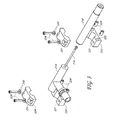
- Figure 2 illustrates a strain gauge assembly 212 connected to the pipe 102.
- an LVDT-type displacement sensor 214 can be used as a strain sensor.
- the displacement sensor 214 can include an armature 216 and armature attachment bar 218.
- the LVDT 214 can be configured to measure the displacement of the armature 216 relative to the armature attachment bar 218. Each end of the LVDT 214 can be held immobile with respect to the pipe being measured so that any displacement of the armature 216 relative to the armature attachment bar 218 would indicate that the pipe is bending under some strain.
- this strain gauge assembly 212 can be connected to the pipe's 102 insulation using clamps 220 near opposing ends of the strain gauge.
- the clamps 220 can be a split-block type clamp, having a clamp base 222 and a clamp top 224. However, other types of clamps can also be used.
- the clamp base 222 can be bonded directly to the insulation, such as by using a thermoplastic weld 228.
- the strain gauge assembly 212 can be held in place by securing the ends of the assembly 212 with two clamps, e.g., with the clamp tops 224 being screwed 226 or otherwise attached to the clamp base 222 with the corresponding portions of the assembly 212 clamped between the corresponding tops 224 and bases 222.
- clamp sections 222, 224 can be attached to threaded dowels 328 to hold the clamp sections 222, 224 in place.
- the clamp sections may be composed of any suitable polypropylene (“PP"), polyethylene (“PE”), or polyvinyl chloride (“PVC”) material.
- the clamp base 222 is preferably composed of a homopolymer polypropylene that is relatively noncompressible under pressure.
- embodiments of clamp sections 222, 224 preferably have any gas bubbles or pockets removed during manufacture to avoid compression and failure at the high pressures of deep water.
- Such material is available, for example, under the commercial name VERSADUR® Homopolymer Polypropylene 500 Natural. However, other materials can also be used.
- Moplen COAT EP/60 BIANCO available from Basell USA, Inc.
- Preferable materials have a relatively low water absorption rate and a relatively low Izod impact strength.
- one preferred material will have a water absorption of about .0100% or less based on the ASTM D 570 standard known to those in the art.
- the fasteners 226, dowels 328, and/or other parts of the fastening components can be made from any suitable material, including but without limitation, stainless steel, Monel 400, etc.
- the clamp 220 can be configured such that a catastrophic impact to the clamp will break the clamp itself with minimal or no damage to the protective coating of the pipe 102.
- Clamps 220 are most preferably made of a material identical to the insulation surface material to which they will be attached. However, it is understood that any co- or homo-polymer polypropylene material with strength, water absorption, Young's modulus, Poisson's ratio, and thermal expansion properties similar to or identical to the particular pipe insulation surface material are also suitable, and other plastics can also be used for the systems and methods disclosed herein.
- the use of matching or substantially matching materials for the clamps 220 and the insulation surface material of the pipe helps ensure the longevity of the strain measurement system.
- Embodiments of the welding technique described herein essentially makes the clamps 220 an extension of the insulation surface material, thereby reducing the complexity and failure potential rather than adding to it as in the prior method of adding new attachment points of different materials.
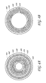
- FIGs 4A and 4B illustrate two insulated pipe configurations for which the strain gauge assembly and attachment methods disclosed herein can be used.
- Catenary risers which can comprise sections of pipe 102 used in oil production often include five layers of insulation and anti-corrosion materials (often known as 5LPP).
- the insulation builds out from the steel with layers of fusion bond epoxy 436, polypropylene adhesive 438, solid polypropylene 440, syntactic polypropylene 442, and solid polypropylene 444 ( Figure 4A ).
- Similar piping is generally used for gas export risers, except that only three layers of insulation are used (often referred to as 3LPP): fusion bond epoxy 436, polypropylene adhesive 438, and solid polypropylene 444 ( Figure 4B ). Regardless of the exact insulation, it is generally preferable to match the material for the clamps 220 with the outer solid polypropylene layer 444.
- 3LPP three layers of insulation
- FIG. 5 is a block diagram of an embodiment of a method of attaching a strain gauge to a catenary riser for strain testing.
- this process occurs on land before transporting a section of pipe to the installation location. It is also possible to attach strain gauges on the ship but the process generally occurs prior to lowering the pipe into the water.
- Hot Gas Hand Welding can be used for attaching the LVDT fixtures to the surface of the 3LPP, 5LPP, or similar coated pipes.
- Hot Gas Welding is generally a manual process using a filler material to perform the weld. The gas (air) simultaneously transmits heat into the parent materials and the welding rod to allow molecular interlocking to take place.
- a Hot Gas Hand Welding system that can be used generally comprises a welding gun, a clean air supply unit, and a welding tip.
- the welding gun typically is provided with a means to adjust the welding temperature.
- One example device that is suitable for this type of welding is the Hot Jet S with speed welding nozzle available from LEISTER.
- Other suitable welding techniques to accomplish welds, particularly, for example, plastic welds, as described herein would be known to those of skill in the art.
- the surface of the insulated piping can be prepared prior to welding the clamps 220 for mounting the strain testing gauge (block 550).
- the Polypropylene surface of the risers can be sanded or otherwise scraped down to virgin material and chemically cleaned.
- the surfaces can be prepared such that they are coplanar with the lower surface of the bases 222 so that the clamp bases are more likely to maintain contact with the pipe's attachment surfaces and limit or avoid air bubbles between the two surfaces. It is also preferred to prepare the pipe surfaces so that the clamps will be placed along the pipe in a manner to hold the displacement sensor 214 in an orientation that is substantially parallel to the longitudinal axis of the pipe.
- Such a preparation process can be performed with an eye towards minimizing the disturbance of the insulation and so as not to damage the overall effectiveness of the insulation. For example, the insulation layers can remain substantially unaltered.
- a scraper can be used to remove the rough outer surface of the polypropylene insulation at each attachment location. Each location is then wiped with a clean cloth to remove dirt, oil, or loose scrapings to provide a better surface for welding. Each base can also be scraped in the area where it will contact the pipe insulation to remove oxidized molecules that may interfere with the welding process.
- an installation or alignment jig 664 can be used to temporarily attach a first clamp base 222 and a second clamp base 222 to the attachment site at the appropriate distance and orientation (block 552). This can help align the bases 222 with their respective installation location marks.
- the alignment jig 664 can be as a pipe having a length and diameter approximate to that of the LVDT 214 and the armature attachment bar 218. Once the bases 222 are in position, the alignment jig 664 and clamps 220 can be temporarily secured to the pipe with a strap 666 or other securing method, such as adhesives, tacks, or the like, to hold the clamp bases in place at the prepared attachment locations.
- the welding gun with a “tacking" tip, can be used to tack the perimeters of the bases 222 onto the outer surface of the insulation of the pipe 102 (block 554).
- a common form of hot gas welding known as "High Speed Welding”
- High Speed Welding can be used to complete the attachment of the clamp bases 222 to the insulation on the pipe 102 (blocks 554, 556).
- High speed welding tips are designed to guide the welding rod into the weld zone while simultaneously heating up the rod and the base material.
- a shoe at the end of the rod orifice allows the operator to apply the welding pressure.
- the welding pressure is dependent on material type and rod size. It is understood that other suitable forms of hot gas welding or other welding techniques can also be used.
- the welder be set to between about 300°C and about 340°C with an air flow volume of about 45 1/min and 55 1/min. Other suitable settings will be apparent to those of skill in the art based on the welding equipment and properties of the materials used. Utilizing a tack weld helps assure that the bases are in proper place and alignment and that they stay in position when additional welding is performed. In some embodiments, the tack welding can be skipped. In other embodiments, the strap 666 and alignment jig 664 can be removed once tack welding is completed. This can help allow easier access to all sides of the clamp bases for the next steps.
- the welding can be completed using regular plastic welding (block 556).
- the welding rod used is preferably scraped before use to clean it and remove any oxidized material, as with the preparation of the clamp bases 222.
- the regular weld preferably surrounds the clamp base to provide the most bonded surface area.
- a first welding pass can be allowed to cool before a subsequent pass. For example, a delay of approximately 3-4 minutes between passes will provide stronger welds - similar to the preferred time to cool the tack welds.
- Compatible materials between the clamp bases 222 and the welding rod filling material can be used to help ensure lasting welds.
- the filler and the bases 222 material can have the same or a close melt flow index.
- One of skill in the art will have familiarity with proper conditions for thermoplastic welding as described herein.
- the LVDT 214 is placed in the slot of one clamp base 222, while the armature attachment bar 218 is placed in the other (block 558).
- the clamp tops are then set in place over the strain gauge pieces and fastened to the clamp bases to hold the strain gauge in place (block 560).
- Fasteners 226, which can be made from Monel 400, Monel 500, Inconel 625, Super Duplex Steels, or other long life corrosion resistant materials, can be bolts (as shown in Fig. 3 ), screws, or other fastening mechanisms and can be used to close the strain sensor clamps 220. Monel is also a preferred material for fasteners 226 because it is additionally resistant to hard marine growth.
- the clamp bases 222 as noted above, can have two threaded dowels 328 inserted into holes 329. The threads can be aligned with clearance holes 331 through the clamp base 222.
- the clamp top 224 can have two clearance holes 331 which can be for ! ⁇ -20 socket head cap screws, which can serve as the fasteners 226, although other sizes can also be used.
- Flat washers 330 can be used here to distribute the load and cross-drilled heads for Monel 400 seizing wire to reduce the likelihood of the fasteners 226 backing out.
- the fasteners 226 can thread into the threaded dowels 328 in the base and can be tightened enough to close the gap between the clamp top 224 and base 222.
- this procedure can be repeated one or more times with additional strain gauges set out at various locations around the circumference of the pipe 102 - generally approximately the same distance along the length of the pipe section. This would allow the collection of data indicative of a pipe bending in a multitude of directions.
- the one or more strain gauge assemblies can be enclosed in a protective casing (block 562).
- This casing is meant to help reduce impact damage to the strain gauges.
- these casings may further be waterproof or water resistant to reduce corrosion of strain gauge components.
- the interior of the casing can be pressure neutralized.
- the casing is a steel shell connected to the pipe with rubber bushings.
- a clamp top 224 can include a flexible or rigid rubber piece that is bolted in place in a manner similar to that shown.
- Another alternative can be a generally U-shaped bolt that would fit around a portion of the strain gauge. It could, for example, be threaded at both ends that would fit through holes in the bottom clamp 222 and be secured by nuts.
- Epoxies or other glues that are degassed, that have a low porosity, and that will not break down in water can also be suitable forms of bonding the strain gauge to the clamp bottoms 222 and/or the clamp bottoms 222 to the insulated pipes.
- preferred alternative epoxies or other glues should be able to maintain their bonds for the expected pipe submersion time of up to approximately 25-30 years or more.
- the mounting blocks can be constructed from materials other than those disclosed herein.
- assembly of the strain gauge in the mounting blocks can utilize any of a variety of suitable fastening devices, including screws, nuts and bolts, adhesives, and the like. Accordingly, other combinations, omissions, substitutions and modifications will be apparent to the skilled artisan in view of the disclosure herein.
Landscapes
- Engineering & Computer Science (AREA)
- Physics & Mathematics (AREA)
- Geology (AREA)
- Life Sciences & Earth Sciences (AREA)
- General Physics & Mathematics (AREA)
- Mining & Mineral Resources (AREA)
- Analytical Chemistry (AREA)
- Chemical & Material Sciences (AREA)
- Mechanical Engineering (AREA)
- Environmental & Geological Engineering (AREA)
- Fluid Mechanics (AREA)
- General Life Sciences & Earth Sciences (AREA)
- Geochemistry & Mineralogy (AREA)
- Measurement Of Length, Angles, Or The Like Using Electric Or Magnetic Means (AREA)
Claims (15)
- Verfahren zum Anbringen eines Sensors an einem Rohr, das Verfahren umfassend:Ausrichten (522) von zumindest zwei Einspannbasen (222) entlang einer Achse parallel zu einer Länge von isoliertem Rohr (102);Verbinden (556) der Einspannbasen (222) mit Isolierung (440; 444), die eine Außenfläche des Rohrs (102) abdeckt;Anordnen (558) einer Sensoranordnung (214) in den Einspannbasen (222); undderartiges Befestigen (560) der Sensoranordnung (214) in den Einspannbasen (222), dass sich die Sensoranordnung (214) nicht innerhalb der Einspannbasen (222) bewegt.
- Verfahren nach Anspruch 1, wobei der Verbindungsschritt (556) durch Schweißen der Einspannbasen (222) unter Verwendung einer Kunststoffschweißung ausgeführt wird; vorzugsweise wobei die Schweißung durch Heißgashandschweißen ausgeführt wird.
- Verfahren nach Anspruch 2, wobei die Isolierung (440; 444) und die zumindest zwei Einspannbasen (222) aus Polypropylen hergestellt sind; vorzugsweise wobei die zumindest zwei Einspannbasen (222) aus Homopolymer-Polypropylen hergestellt sind.
- Verfahren nach einem der Ansprüche 2 oder 3, wobei die zumindest zwei Einspannbasen (222) aus einem Material hergestellt sind, das mit der Isolierung (440; 444) zusammenpasst, welche die Außenfläche des Rohrs (102) abdeckt, und derart gebaut sind, dass die Einspannbasen (222) unter Schlagbeanspruchung versagen, bevor die Beanspruchung die Isolierung (440; 444) des Rohrs beschädigt.
- Verfahren nach einem der Ansprüche 2, 3 oder 4, wobei die Schritte von Anspruch 2 für mehrfache Sensoranordnungen (214), die an verschiedenen Stellen um einen Umfang des Rohrs (102) angeordnet werden, wiederholt werden.
- Verfahren nach einem der vorhergehenden Ansprüche, wobei zum Unterstützen beim Verbinden der Einspannbasen (222) keine dauerhaften Bänder benutzt werden.
- Belastungsmessgerät- und Rohranordnung, umfassend:eine Länge Rohr (102) mit einer oder mehr Schichten aus Polypropylenisolierung (440; 444);zumindest zwei Einspannbasen (222), die an die Isolierungsaußenschicht (440, 444) geschweißt sind; undeinen Verschiebungssensor (214), der derart an die zumindest zwei Einspannbasen (222) angebracht ist, dass der Verschiebungssensor (214) bezüglich der zwei Einspannbasen (222) unbeweglich ist und Verschiebung proportional zum Biegen der Länge Rohr (102) registriert.
- Anordnung nach Anspruch 7, wobei der Verschiebungssensor (214) an einer Einspannbasis (222) an einem Ende im Wesentlichen gegenüber einem Anbringungspunkt des Verschiebungssensors (214) an einer anderen der Einspannbasen (222) angebracht ist.
- Anordnung nach einem der Ansprüche 7 oder 8, ferner umfassend zumindest einen zweiten Verschiebungssensor (214), der an einem anderen Abschnitt der Isolierungsaußenschicht (440; 444) durch zumindest eine Einspannbasis (222) angebracht ist, wobei der Verschiebungssensor und der zweite Verschiebungssensor zum Registrieren von Verschiebung proportional zum Biegen der Länge Rohr (102) in verschiedenen Ebenen imstande sind.
- Anordnung nach einem der Ansprüche 7, 8 oder 9, ferner umfassend ein Schutzgehäuse, das den Verschiebungssensor (214) im Wesentlichen innerhalb eines Hohlraums des Gehäuses einschließt.
- Anordnung nach einem der Ansprüche 7, 8, 9 oder 10, wobei jede Einspannbasis (222) durch eine Kunststoffschweißung an die Isolieraußenschicht (440; 444) geschweißt ist.
- Anordnung nach einem der Ansprüche 7, 8, 9, 10 oder 11, wobei jede Einspannbasis (222) aus einem Material hergestellt ist, das der Isolieraußenschicht (440; 444) im Wesentlichen ähnelt; vorzugsweise wobei jede Einspannbasis (222) aus einem Material hergestellt ist, das mit der Isolieraußenschicht (440; 444) identisch ist.
- Vorrichtung zum Anbringen eines Belastungsmessgeräts (214) an einer Länge von isoliertem Rohr (102), umfassend:eine erste Einspannbasis (222) mit einem Hohlraum, der zum Annehmen eines ersten Abschnitts eines Belastungsmessgeräts (214) geeignet ist, wobei die Einspannbasis (222) dazu geeignet ist, an die Isolierung (440; 444) auf einem Rohr (102) geschweißt zu sein;eine erste Einspannoberseite (224), die zum Halten des ersten Abschnitts eines Belastungsmessgeräts (214) zu halten, der innerhalb des Hohlraums der ersten Basis (222) festgesetzt ist;eine zweite Einspannbasis (222) mit einem zweiten Hohlraum, der zum Annehmen eines zweiten Abschnitts eines Belastungsmessgeräts (214) geeignet ist, wobei die Einspannbasis (222) dazu geeignet ist, an die Isolierung (440; 444) geschweißt zu sein; undeine zweite Einspannoberseite (224), die zum Halten des zweiten Abschnitts des Belastungsmessgeräts (214) zu halten, der innerhalb des zweiten der zweiten Einspannbasis (222) festgesetzt ist,wobei jegliche Bewegung des ersten Abschnitts des Belastungsmessgeräts (214) bezüglich des zweiten Abschnitts des Belastungsmessgeräts (214) eine Belastung auf das darunter liegende Rohr (102) anzeigt.
- Vorrichtung nach Anspruch 13, wobei die erste und zweite Einspannbasis (222) ein Kunststoffmaterial umfassen und dazu geeignet sind, unter Verwendung einer Kunststoffschweißung an die Isolierung (440; 444) geschweißt zu sein; und/oder wobei die erste und zweite Einspannoberseite (224) ein korrosionsbeständiges Material, vorzugsweise eine korrosionsbeständige Beschichtung, enthalten.
- Vorrichtung nach einem der Ansprüche 13 oder 14, wobei die erste und zweite Einspannoberseite (224) jede ein Kunststoffstück enthalten, das zum Halten der jeweiligen Abschnitte des Belastungsmessers (214) in den Hohlräumen der jeweiligen ersten und zweiten Einspannbasis (222) geeignet ist, und wobei die erste und zweite Einspannbasis (222) jede zum Annehmen von zumindest einem Befestigungselement zum Festhalten der jeweiligen Kunststoffstücke und Belastungsmessgerätabschnitte geeignet sind.
Applications Claiming Priority (2)
| Application Number | Priority Date | Filing Date | Title |
|---|---|---|---|
| US94327507P | 2007-06-11 | 2007-06-11 | |
| PCT/US2008/066606 WO2008154604A1 (en) | 2007-06-11 | 2008-06-11 | Device and method for providing strain measurements of insulated pipes |
Publications (3)
| Publication Number | Publication Date |
|---|---|
| EP2167735A1 EP2167735A1 (de) | 2010-03-31 |
| EP2167735A4 EP2167735A4 (de) | 2013-01-02 |
| EP2167735B1 true EP2167735B1 (de) | 2014-07-23 |
Family
ID=40095219
Family Applications (1)
| Application Number | Title | Priority Date | Filing Date |
|---|---|---|---|
| EP08770749.3A Not-in-force EP2167735B1 (de) | 2007-06-11 | 2008-06-11 | Vorrichtung und verfahren zur bereitstellung von dehnungsmessungen von isolierten rohren |
Country Status (4)
| Country | Link |
|---|---|
| US (1) | US7891254B2 (de) |
| EP (1) | EP2167735B1 (de) |
| BR (1) | BRPI0812503A2 (de) |
| WO (1) | WO2008154604A1 (de) |
Families Citing this family (19)
| Publication number | Priority date | Publication date | Assignee | Title |
|---|---|---|---|---|
| JP5341855B2 (ja) * | 2010-10-01 | 2013-11-13 | 日本分光株式会社 | 微小容量圧力計 |
| BR112013012653A2 (pt) | 2010-11-23 | 2017-06-27 | Bmt Scient Marine Services Inc | sistemas de controle e de montagem de sensor para membro tubular subaquático e método de instalação de sistema de monitoração à distância com elemento tubular |
| CN102778311B (zh) * | 2012-07-23 | 2014-04-16 | 北京航空航天大学 | 一种井下抽油杆多维径向压力测量装置 |
| WO2014016784A2 (en) * | 2012-07-24 | 2014-01-30 | Services Petroliers Schlumberger | Displacement sensor for subsea structures |
| CN103567582B (zh) * | 2012-07-25 | 2015-07-15 | 中冶建筑研究总院有限公司 | 一种构件外表面安装应变传感器的方法 |
| US9618435B2 (en) * | 2014-03-31 | 2017-04-11 | Dmar Engineering, Inc. | Umbilical bend-testing |
| GB201506496D0 (en) | 2015-04-16 | 2015-06-03 | Expro North Sea Ltd | Measurement system and methods |
| CN106323508A (zh) * | 2015-06-29 | 2017-01-11 | 中国二十冶集团有限公司 | 一种应力计安装方法 |
| CN108036760A (zh) * | 2017-11-30 | 2018-05-15 | 雄邦压铸(南通)有限公司 | 新能源汽车车身结构件变形检测及校形方法 |
| US11187603B2 (en) * | 2018-06-11 | 2021-11-30 | Oil States Industries, Inc. | Variable reluctance measurement technology for drilling risers and riser towers |
| WO2020037388A1 (en) * | 2018-08-18 | 2020-02-27 | Monflex Tec Engenharia De Integridade Ltda. | System for monitoring the integrity of risers and maritime structures using deformation sensors installed by clamps, and methods for installing and calibrating the pre-tension on deformation sensors for monitoring the integrity of risers |
| CN109520465B (zh) * | 2019-01-08 | 2024-08-16 | 同济大学 | 标距可调式应变传感器固定装置 |
| CN109540496B (zh) * | 2019-01-10 | 2023-10-13 | 西南石油大学 | 一种用于研究盐穴库输送管道变形强度的实验装置及方法 |
| JP7203645B2 (ja) * | 2019-03-11 | 2023-01-13 | 日本電産コパル電子株式会社 | ロードセル |
| GB202002029D0 (en) * | 2020-02-14 | 2020-04-01 | Trelleborg Offshore Uk Ltd | A device for monitoring strain of an elongate underwater member |
| CN111366527B (zh) * | 2020-04-01 | 2021-10-08 | 大连理工大学 | 适用于研究金属材料应力腐蚀的多通道腐蚀监测系统 |
| CN112577826B (zh) * | 2020-12-02 | 2022-12-23 | 天津大学 | 一种模拟深水环境下管道均布荷载的试验平台 |
| CN112577827B (zh) * | 2020-12-02 | 2022-03-29 | 天津大学 | 一种模拟深水环境下管道均布荷载的试验方法 |
| CN119164816A (zh) * | 2024-11-21 | 2024-12-20 | 大安吉电绿氢能源有限公司 | 埋地管外防护层损伤模拟实验装置 |
Family Cites Families (15)
| Publication number | Priority date | Publication date | Assignee | Title |
|---|---|---|---|---|
| US3857452A (en) * | 1974-02-14 | 1974-12-31 | Tri Coastal Ind Inc | Dump truck load-sensing assembly |
| DE3151048C2 (de) * | 1981-12-23 | 1985-03-21 | Paul Forkardt GmbH & Co KG, 4000 Düsseldorf | Spannkraftaufnehmer für umlaufende Spanneinrichtungen |
| US4932253A (en) * | 1989-05-02 | 1990-06-12 | Mccoy James N | Rod mounted load cell |
| AU4254296A (en) * | 1994-11-21 | 1996-06-17 | Ulrike Richter | Butt-welding device for pipes made of thermoplastic materials |
| US5813658A (en) * | 1994-11-23 | 1998-09-29 | Arnco Corporation | Cable feeding apparatus |
| US6315497B1 (en) * | 1995-12-29 | 2001-11-13 | Shell Oil Company | Joint for applying current across a pipe-in-pipe system |
| US6292436B1 (en) * | 1997-10-01 | 2001-09-18 | Input/Output, Inc. | Underwater cable arrangements, internal devices for use in an underwater cable, and methods of connecting and internal device to a stress member of an underwater cable |
| WO2000000799A1 (en) * | 1998-06-26 | 2000-01-06 | Cidra Corporation | Non-intrusive fiber optic pressure sensor for measuring unsteady pressures within a pipe |
| US6374893B1 (en) * | 1998-07-23 | 2002-04-23 | Leonard Iven Behl | Plastic welder |
| US7194913B2 (en) * | 2002-08-26 | 2007-03-27 | Shell Oil Company | Apparatuses and methods for monitoring stress in steel catenary risers |
| US7343818B2 (en) * | 2003-01-21 | 2008-03-18 | Cidra Corporation | Apparatus and method of measuring gas volume fraction of a fluid flowing within a pipe |
| US7171315B2 (en) * | 2003-11-25 | 2007-01-30 | Cidra Corporation | Method and apparatus for measuring a parameter of a fluid flowing within a pipe using sub-array processing |
| AU2005302031B2 (en) | 2004-11-03 | 2008-10-09 | Shell Internationale Research Maatschappij B.V. | Apparatus and method for retroactively installing sensors on marine elements |
| GB2431974B (en) | 2005-11-01 | 2010-12-08 | Corus Uk Ltd | Insulation coating for pipework |
| CN201278404Y (zh) * | 2008-09-16 | 2009-07-22 | 富士康(昆山)电脑接插件有限公司 | 电连接器组件 |
-
2008
- 2008-06-11 EP EP08770749.3A patent/EP2167735B1/de not_active Not-in-force
- 2008-06-11 US US12/137,427 patent/US7891254B2/en active Active
- 2008-06-11 BR BRPI0812503-1A patent/BRPI0812503A2/pt not_active IP Right Cessation
- 2008-06-11 WO PCT/US2008/066606 patent/WO2008154604A1/en not_active Ceased
Also Published As
| Publication number | Publication date |
|---|---|
| US7891254B2 (en) | 2011-02-22 |
| EP2167735A1 (de) | 2010-03-31 |
| WO2008154604A8 (en) | 2010-01-28 |
| BRPI0812503A2 (pt) | 2015-06-16 |
| US20080303382A1 (en) | 2008-12-11 |
| WO2008154604A1 (en) | 2008-12-18 |
| EP2167735A4 (de) | 2013-01-02 |
Similar Documents
| Publication | Publication Date | Title |
|---|---|---|
| EP2167735B1 (de) | Vorrichtung und verfahren zur bereitstellung von dehnungsmessungen von isolierten rohren | |
| US8366351B2 (en) | Method of making an undersea pipe including anticorrosion linings and welds | |
| US6739803B2 (en) | Method of installation of electrically heated pipe-in-pipe subsea pipeline | |
| EP3280940B1 (de) | Verfahren zur installation eines elektrisch erwärmbaren unterwasserflussleitung | |
| JPS62124393A (ja) | 水中ダクト用断熱装置 | |
| EP3947822B1 (de) | Vorrichtung zum bewegen entlang einer zylindrischen struktur und ihre verwendung sowie verfahren zum bearbeiten einer zylindrischen struktur | |
| WO2009122166A2 (en) | Complex pipe monitoring | |
| CA2875633C (en) | Pipeline and methods to provide cathodic protection to a pipeline | |
| EP2815057B1 (de) | Bewegungsbegrenzer für an hybride-steigrohrtürme befestigte strukturen | |
| US7651137B2 (en) | Insulated pipe joint | |
| WO2010049667A1 (en) | Apparatus and method for reducing stress across subsea pipe joints | |
| BR102018012268B1 (pt) | Sistema para inspeção de um reparo ou junta de material composto aplicado a uma estrutura | |
| BR112018006023B1 (pt) | Método para produção de um oleoduto revestido com um sistema de monitoramento de integridade, método para monitorar a integridade de um oleoduto revestido, encaixe de eletrofusão e oleoduto revestido | |
| NO335353B1 (no) | Isolerende kobling for elektrisk oppvarmet rørledning | |
| EP0132332B1 (de) | Kathodisches Schutzsystem für Rohrleitungen | |
| Seaman et al. | Development and testing of a post-installable deepwater monitoring system using fiber-optic sensors | |
| CN116659559A (zh) | 一种水下传感器安装装置及更换方法 | |
| Knudsen et al. | SmartPipe: Self Diagnostic Pipelines and Risers | |
| Guan et al. | Novel Thermal Insulation Systems for Deepwater and Arctic Pipelines Based on Styrenic Alloys | |
| Walsh et al. | Application of learnings from the assessment of cathodic protection and coatings on a recovered marine pipeline end termination | |
| CcORMRPOESRITpIEp | Tests verify suitability of GRP in sub-sea pipes | |
| Netto et al. | Repair Techniques for Flexible Pipe External Sheath | |
| Thomas et al. | External Pitting And Crevice Corrosion Of 316L Stainless Steel Instrument Tubing In Marine Environments And Proposed Solution | |
| BR102017017283B1 (pt) | Dispositivo bipartido para aplicação de resina em reparo de um duto flexível e/ou monitoramento de duto rígido | |
| BR102017017283A2 (pt) | Dispositivo bipartido para aplicação de resina em reparo de um duto flexível e/ou monitoramento de duto rígido |
Legal Events
| Date | Code | Title | Description |
|---|---|---|---|
| PUAI | Public reference made under article 153(3) epc to a published international application that has entered the european phase |
Free format text: ORIGINAL CODE: 0009012 |
|
| 17P | Request for examination filed |
Effective date: 20091228 |
|
| AK | Designated contracting states |
Kind code of ref document: A1 Designated state(s): AT BE BG CH CY CZ DE DK EE ES FI FR GB GR HR HU IE IS IT LI LT LU LV MC MT NL NO PL PT RO SE SI SK TR |
|
| AX | Request for extension of the european patent |
Extension state: AL BA MK RS |
|
| DAX | Request for extension of the european patent (deleted) | ||
| A4 | Supplementary search report drawn up and despatched |
Effective date: 20121203 |
|
| RIC1 | Information provided on ipc code assigned before grant |
Ipc: E02D 5/02 20060101AFI20121127BHEP Ipc: E21B 17/01 20060101ALI20121127BHEP Ipc: G01B 21/32 20060101ALI20121127BHEP Ipc: G01L 5/10 20060101ALI20121127BHEP |
|
| RIC1 | Information provided on ipc code assigned before grant |
Ipc: G01L 5/10 20060101ALI20131129BHEP Ipc: E02D 5/02 20060101AFI20131129BHEP Ipc: E21B 17/01 20060101ALI20131129BHEP Ipc: G01B 21/32 20060101ALI20131129BHEP |
|
| GRAP | Despatch of communication of intention to grant a patent |
Free format text: ORIGINAL CODE: EPIDOSNIGR1 |
|
| INTG | Intention to grant announced |
Effective date: 20140129 |
|
| GRAS | Grant fee paid |
Free format text: ORIGINAL CODE: EPIDOSNIGR3 |
|
| GRAA | (expected) grant |
Free format text: ORIGINAL CODE: 0009210 |
|
| AK | Designated contracting states |
Kind code of ref document: B1 Designated state(s): AT BE BG CH CY CZ DE DK EE ES FI FR GB GR HR HU IE IS IT LI LT LU LV MC MT NL NO PL PT RO SE SI SK TR |
|
| REG | Reference to a national code |
Ref country code: GB Ref legal event code: FG4D |
|
| REG | Reference to a national code |
Ref country code: CH Ref legal event code: EP |
|
| REG | Reference to a national code |
Ref country code: IE Ref legal event code: FG4D |
|
| REG | Reference to a national code |
Ref country code: AT Ref legal event code: REF Ref document number: 678976 Country of ref document: AT Kind code of ref document: T Effective date: 20140815 |
|
| REG | Reference to a national code |
Ref country code: DE Ref legal event code: R096 Ref document number: 602008033465 Country of ref document: DE Effective date: 20140904 |
|
| REG | Reference to a national code |
Ref country code: AT Ref legal event code: MK05 Ref document number: 678976 Country of ref document: AT Kind code of ref document: T Effective date: 20140723 |
|
| REG | Reference to a national code |
Ref country code: NL Ref legal event code: VDEP Effective date: 20140723 |
|
| REG | Reference to a national code |
Ref country code: LT Ref legal event code: MG4D |
|
| PG25 | Lapsed in a contracting state [announced via postgrant information from national office to epo] |
Ref country code: GR Free format text: LAPSE BECAUSE OF FAILURE TO SUBMIT A TRANSLATION OF THE DESCRIPTION OR TO PAY THE FEE WITHIN THE PRESCRIBED TIME-LIMIT Effective date: 20141024 Ref country code: PT Free format text: LAPSE BECAUSE OF FAILURE TO SUBMIT A TRANSLATION OF THE DESCRIPTION OR TO PAY THE FEE WITHIN THE PRESCRIBED TIME-LIMIT Effective date: 20141124 Ref country code: NO Free format text: LAPSE BECAUSE OF FAILURE TO SUBMIT A TRANSLATION OF THE DESCRIPTION OR TO PAY THE FEE WITHIN THE PRESCRIBED TIME-LIMIT Effective date: 20141023 Ref country code: BG Free format text: LAPSE BECAUSE OF FAILURE TO SUBMIT A TRANSLATION OF THE DESCRIPTION OR TO PAY THE FEE WITHIN THE PRESCRIBED TIME-LIMIT Effective date: 20141023 Ref country code: LT Free format text: LAPSE BECAUSE OF FAILURE TO SUBMIT A TRANSLATION OF THE DESCRIPTION OR TO PAY THE FEE WITHIN THE PRESCRIBED TIME-LIMIT Effective date: 20140723 Ref country code: SE Free format text: LAPSE BECAUSE OF FAILURE TO SUBMIT A TRANSLATION OF THE DESCRIPTION OR TO PAY THE FEE WITHIN THE PRESCRIBED TIME-LIMIT Effective date: 20140723 Ref country code: FI Free format text: LAPSE BECAUSE OF FAILURE TO SUBMIT A TRANSLATION OF THE DESCRIPTION OR TO PAY THE FEE WITHIN THE PRESCRIBED TIME-LIMIT Effective date: 20140723 Ref country code: ES Free format text: LAPSE BECAUSE OF FAILURE TO SUBMIT A TRANSLATION OF THE DESCRIPTION OR TO PAY THE FEE WITHIN THE PRESCRIBED TIME-LIMIT Effective date: 20140723 |
|
| PG25 | Lapsed in a contracting state [announced via postgrant information from national office to epo] |
Ref country code: HR Free format text: LAPSE BECAUSE OF FAILURE TO SUBMIT A TRANSLATION OF THE DESCRIPTION OR TO PAY THE FEE WITHIN THE PRESCRIBED TIME-LIMIT Effective date: 20140723 Ref country code: AT Free format text: LAPSE BECAUSE OF FAILURE TO SUBMIT A TRANSLATION OF THE DESCRIPTION OR TO PAY THE FEE WITHIN THE PRESCRIBED TIME-LIMIT Effective date: 20140723 Ref country code: CY Free format text: LAPSE BECAUSE OF FAILURE TO SUBMIT A TRANSLATION OF THE DESCRIPTION OR TO PAY THE FEE WITHIN THE PRESCRIBED TIME-LIMIT Effective date: 20140723 Ref country code: IS Free format text: LAPSE BECAUSE OF FAILURE TO SUBMIT A TRANSLATION OF THE DESCRIPTION OR TO PAY THE FEE WITHIN THE PRESCRIBED TIME-LIMIT Effective date: 20141123 Ref country code: LV Free format text: LAPSE BECAUSE OF FAILURE TO SUBMIT A TRANSLATION OF THE DESCRIPTION OR TO PAY THE FEE WITHIN THE PRESCRIBED TIME-LIMIT Effective date: 20140723 Ref country code: PL Free format text: LAPSE BECAUSE OF FAILURE TO SUBMIT A TRANSLATION OF THE DESCRIPTION OR TO PAY THE FEE WITHIN THE PRESCRIBED TIME-LIMIT Effective date: 20140723 Ref country code: NL Free format text: LAPSE BECAUSE OF FAILURE TO SUBMIT A TRANSLATION OF THE DESCRIPTION OR TO PAY THE FEE WITHIN THE PRESCRIBED TIME-LIMIT Effective date: 20140723 |
|
| REG | Reference to a national code |
Ref country code: DE Ref legal event code: R097 Ref document number: 602008033465 Country of ref document: DE |
|
| PG25 | Lapsed in a contracting state [announced via postgrant information from national office to epo] |
Ref country code: SK Free format text: LAPSE BECAUSE OF FAILURE TO SUBMIT A TRANSLATION OF THE DESCRIPTION OR TO PAY THE FEE WITHIN THE PRESCRIBED TIME-LIMIT Effective date: 20140723 Ref country code: EE Free format text: LAPSE BECAUSE OF FAILURE TO SUBMIT A TRANSLATION OF THE DESCRIPTION OR TO PAY THE FEE WITHIN THE PRESCRIBED TIME-LIMIT Effective date: 20140723 Ref country code: CZ Free format text: LAPSE BECAUSE OF FAILURE TO SUBMIT A TRANSLATION OF THE DESCRIPTION OR TO PAY THE FEE WITHIN THE PRESCRIBED TIME-LIMIT Effective date: 20140723 Ref country code: IT Free format text: LAPSE BECAUSE OF FAILURE TO SUBMIT A TRANSLATION OF THE DESCRIPTION OR TO PAY THE FEE WITHIN THE PRESCRIBED TIME-LIMIT Effective date: 20140723 Ref country code: DK Free format text: LAPSE BECAUSE OF FAILURE TO SUBMIT A TRANSLATION OF THE DESCRIPTION OR TO PAY THE FEE WITHIN THE PRESCRIBED TIME-LIMIT Effective date: 20140723 Ref country code: RO Free format text: LAPSE BECAUSE OF FAILURE TO SUBMIT A TRANSLATION OF THE DESCRIPTION OR TO PAY THE FEE WITHIN THE PRESCRIBED TIME-LIMIT Effective date: 20140723 |
|
| PLBE | No opposition filed within time limit |
Free format text: ORIGINAL CODE: 0009261 |
|
| STAA | Information on the status of an ep patent application or granted ep patent |
Free format text: STATUS: NO OPPOSITION FILED WITHIN TIME LIMIT |
|
| 26N | No opposition filed |
Effective date: 20150424 |
|
| PG25 | Lapsed in a contracting state [announced via postgrant information from national office to epo] |
Ref country code: SI Free format text: LAPSE BECAUSE OF FAILURE TO SUBMIT A TRANSLATION OF THE DESCRIPTION OR TO PAY THE FEE WITHIN THE PRESCRIBED TIME-LIMIT Effective date: 20140723 |
|
| REG | Reference to a national code |
Ref country code: DE Ref legal event code: R119 Ref document number: 602008033465 Country of ref document: DE |
|
| PG25 | Lapsed in a contracting state [announced via postgrant information from national office to epo] |
Ref country code: MC Free format text: LAPSE BECAUSE OF FAILURE TO SUBMIT A TRANSLATION OF THE DESCRIPTION OR TO PAY THE FEE WITHIN THE PRESCRIBED TIME-LIMIT Effective date: 20140723 |
|
| REG | Reference to a national code |
Ref country code: CH Ref legal event code: PL |
|
| GBPC | Gb: european patent ceased through non-payment of renewal fee |
Effective date: 20150611 |
|
| PG25 | Lapsed in a contracting state [announced via postgrant information from national office to epo] |
Ref country code: LU Free format text: LAPSE BECAUSE OF FAILURE TO SUBMIT A TRANSLATION OF THE DESCRIPTION OR TO PAY THE FEE WITHIN THE PRESCRIBED TIME-LIMIT Effective date: 20150611 |
|
| REG | Reference to a national code |
Ref country code: IE Ref legal event code: MM4A |
|
| REG | Reference to a national code |
Ref country code: FR Ref legal event code: ST Effective date: 20160229 |
|
| PG25 | Lapsed in a contracting state [announced via postgrant information from national office to epo] |
Ref country code: IE Free format text: LAPSE BECAUSE OF NON-PAYMENT OF DUE FEES Effective date: 20150611 Ref country code: DE Free format text: LAPSE BECAUSE OF NON-PAYMENT OF DUE FEES Effective date: 20160101 Ref country code: CH Free format text: LAPSE BECAUSE OF NON-PAYMENT OF DUE FEES Effective date: 20150630 Ref country code: LI Free format text: LAPSE BECAUSE OF NON-PAYMENT OF DUE FEES Effective date: 20150630 Ref country code: GB Free format text: LAPSE BECAUSE OF NON-PAYMENT OF DUE FEES Effective date: 20150611 |
|
| PG25 | Lapsed in a contracting state [announced via postgrant information from national office to epo] |
Ref country code: FR Free format text: LAPSE BECAUSE OF NON-PAYMENT OF DUE FEES Effective date: 20150630 |
|
| PG25 | Lapsed in a contracting state [announced via postgrant information from national office to epo] |
Ref country code: BE Free format text: LAPSE BECAUSE OF FAILURE TO SUBMIT A TRANSLATION OF THE DESCRIPTION OR TO PAY THE FEE WITHIN THE PRESCRIBED TIME-LIMIT Effective date: 20140723 |
|
| PG25 | Lapsed in a contracting state [announced via postgrant information from national office to epo] |
Ref country code: MT Free format text: LAPSE BECAUSE OF FAILURE TO SUBMIT A TRANSLATION OF THE DESCRIPTION OR TO PAY THE FEE WITHIN THE PRESCRIBED TIME-LIMIT Effective date: 20140723 |
|
| PG25 | Lapsed in a contracting state [announced via postgrant information from national office to epo] |
Ref country code: HU Free format text: LAPSE BECAUSE OF FAILURE TO SUBMIT A TRANSLATION OF THE DESCRIPTION OR TO PAY THE FEE WITHIN THE PRESCRIBED TIME-LIMIT; INVALID AB INITIO Effective date: 20080611 |
|
| PG25 | Lapsed in a contracting state [announced via postgrant information from national office to epo] |
Ref country code: TR Free format text: LAPSE BECAUSE OF FAILURE TO SUBMIT A TRANSLATION OF THE DESCRIPTION OR TO PAY THE FEE WITHIN THE PRESCRIBED TIME-LIMIT Effective date: 20140723 |