EP2167189B1 - Telemetry listening window management for an implantable medical device - Google Patents
Telemetry listening window management for an implantable medical device Download PDFInfo
- Publication number
- EP2167189B1 EP2167189B1 EP08771858.1A EP08771858A EP2167189B1 EP 2167189 B1 EP2167189 B1 EP 2167189B1 EP 08771858 A EP08771858 A EP 08771858A EP 2167189 B1 EP2167189 B1 EP 2167189B1
- Authority
- EP
- European Patent Office
- Prior art keywords
- coil
- stimulation
- telemetry
- inter
- microstimulator
- Prior art date
- Legal status (The legal status is an assumption and is not a legal conclusion. Google has not performed a legal analysis and makes no representation as to the accuracy of the status listed.)
- Not-in-force
Links
- 230000000638 stimulation Effects 0.000 claims description 59
- 239000003990 capacitor Substances 0.000 claims description 20
- 238000004891 communication Methods 0.000 claims description 2
- 230000008878 coupling Effects 0.000 claims description 2
- 238000010168 coupling process Methods 0.000 claims description 2
- 238000005859 coupling reaction Methods 0.000 claims description 2
- 238000000034 method Methods 0.000 description 15
- 210000001519 tissue Anatomy 0.000 description 8
- 238000002560 therapeutic procedure Methods 0.000 description 6
- 230000004048 modification Effects 0.000 description 5
- 238000007599 discharging Methods 0.000 description 4
- 230000001225 therapeutic effect Effects 0.000 description 4
- 238000010420 art technique Methods 0.000 description 3
- 238000013461 design Methods 0.000 description 3
- 210000000278 spinal cord Anatomy 0.000 description 3
- 208000037265 diseases, disorders, signs and symptoms Diseases 0.000 description 2
- 208000035475 disorder Diseases 0.000 description 2
- 230000000694 effects Effects 0.000 description 2
- 238000012986 modification Methods 0.000 description 2
- 210000005036 nerve Anatomy 0.000 description 2
- 230000001537 neural effect Effects 0.000 description 2
- 201000004569 Blindness Diseases 0.000 description 1
- 208000000094 Chronic Pain Diseases 0.000 description 1
- 206010011878 Deafness Diseases 0.000 description 1
- 208000019695 Migraine disease Diseases 0.000 description 1
- 206010027603 Migraine headaches Diseases 0.000 description 1
- 208000019430 Motor disease Diseases 0.000 description 1
- 208000002193 Pain Diseases 0.000 description 1
- 206010046543 Urinary incontinence Diseases 0.000 description 1
- UELITFHSCLAHKR-UHFFFAOYSA-N acibenzolar-S-methyl Chemical compound CSC(=O)C1=CC=CC2=C1SN=N2 UELITFHSCLAHKR-UHFFFAOYSA-N 0.000 description 1
- 230000004913 activation Effects 0.000 description 1
- 206010003119 arrhythmia Diseases 0.000 description 1
- 230000008901 benefit Effects 0.000 description 1
- 210000004556 brain Anatomy 0.000 description 1
- 206010061592 cardiac fibrillation Diseases 0.000 description 1
- 230000001054 cortical effect Effects 0.000 description 1
- 231100000895 deafness Toxicity 0.000 description 1
- 208000016354 hearing loss disease Diseases 0.000 description 1
- 239000007943 implant Substances 0.000 description 1
- 238000002347 injection Methods 0.000 description 1
- 239000007924 injection Substances 0.000 description 1
- 210000003205 muscle Anatomy 0.000 description 1
- 230000002035 prolonged effect Effects 0.000 description 1
- 208000020016 psychiatric disease Diseases 0.000 description 1
- 238000011084 recovery Methods 0.000 description 1
- 230000002207 retinal effect Effects 0.000 description 1
- 238000012552 review Methods 0.000 description 1
- 201000002859 sleep apnea Diseases 0.000 description 1
- 230000004936 stimulating effect Effects 0.000 description 1
Images
Classifications
-
- A—HUMAN NECESSITIES
- A61—MEDICAL OR VETERINARY SCIENCE; HYGIENE
- A61N—ELECTROTHERAPY; MAGNETOTHERAPY; RADIATION THERAPY; ULTRASOUND THERAPY
- A61N1/00—Electrotherapy; Circuits therefor
- A61N1/18—Applying electric currents by contact electrodes
- A61N1/32—Applying electric currents by contact electrodes alternating or intermittent currents
- A61N1/36—Applying electric currents by contact electrodes alternating or intermittent currents for stimulation
- A61N1/372—Arrangements in connection with the implantation of stimulators
- A61N1/37211—Means for communicating with stimulators
- A61N1/37252—Details of algorithms or data aspects of communication system, e.g. handshaking, transmitting specific data or segmenting data
-
- A—HUMAN NECESSITIES
- A61—MEDICAL OR VETERINARY SCIENCE; HYGIENE
- A61N—ELECTROTHERAPY; MAGNETOTHERAPY; RADIATION THERAPY; ULTRASOUND THERAPY
- A61N1/00—Electrotherapy; Circuits therefor
- A61N1/18—Applying electric currents by contact electrodes
- A61N1/32—Applying electric currents by contact electrodes alternating or intermittent currents
- A61N1/36—Applying electric currents by contact electrodes alternating or intermittent currents for stimulation
- A61N1/372—Arrangements in connection with the implantation of stimulators
- A61N1/37205—Microstimulators, e.g. implantable through a cannula
-
- A—HUMAN NECESSITIES
- A61—MEDICAL OR VETERINARY SCIENCE; HYGIENE
- A61N—ELECTROTHERAPY; MAGNETOTHERAPY; RADIATION THERAPY; ULTRASOUND THERAPY
- A61N1/00—Electrotherapy; Circuits therefor
- A61N1/18—Applying electric currents by contact electrodes
- A61N1/32—Applying electric currents by contact electrodes alternating or intermittent currents
- A61N1/36—Applying electric currents by contact electrodes alternating or intermittent currents for stimulation
- A61N1/3605—Implantable neurostimulators for stimulating central or peripheral nerve system
-
- A—HUMAN NECESSITIES
- A61—MEDICAL OR VETERINARY SCIENCE; HYGIENE
- A61N—ELECTROTHERAPY; MAGNETOTHERAPY; RADIATION THERAPY; ULTRASOUND THERAPY
- A61N1/00—Electrotherapy; Circuits therefor
- A61N1/18—Applying electric currents by contact electrodes
- A61N1/32—Applying electric currents by contact electrodes alternating or intermittent currents
- A61N1/36—Applying electric currents by contact electrodes alternating or intermittent currents for stimulation
- A61N1/372—Arrangements in connection with the implantation of stimulators
- A61N1/37211—Means for communicating with stimulators
- A61N1/37252—Details of algorithms or data aspects of communication system, e.g. handshaking, transmitting specific data or segmenting data
- A61N1/37254—Pacemaker or defibrillator security, e.g. to prevent or inhibit programming alterations by hackers or unauthorised individuals
-
- Y—GENERAL TAGGING OF NEW TECHNOLOGICAL DEVELOPMENTS; GENERAL TAGGING OF CROSS-SECTIONAL TECHNOLOGIES SPANNING OVER SEVERAL SECTIONS OF THE IPC; TECHNICAL SUBJECTS COVERED BY FORMER USPC CROSS-REFERENCE ART COLLECTIONS [XRACs] AND DIGESTS
- Y10—TECHNICAL SUBJECTS COVERED BY FORMER USPC
- Y10S—TECHNICAL SUBJECTS COVERED BY FORMER USPC CROSS-REFERENCE ART COLLECTIONS [XRACs] AND DIGESTS
- Y10S128/00—Surgery
- Y10S128/903—Radio telemetry
Definitions
- the present invention relates generally to implantable stimulator devices, e.g., an implantable pulse generator such as a Bion® device, a Spinal Cord Stimulation (SCS) device, or other type of neural stimulation devices.
- implantable stimulator devices e.g., an implantable pulse generator such as a Bion® device, a Spinal Cord Stimulation (SCS) device, or other type of neural stimulation devices.
- an implantable pulse generator such as a Bion® device, a Spinal Cord Stimulation (SCS) device, or other type of neural stimulation devices.
- SCS Spinal Cord Stimulation
- Implantable stimulation devices generate and deliver electrical stimuli to nerves and tissues for the therapy of various biological disorders, such as pacemakers to treat cardiac arrhythmia, defibrillators to treat cardiac fibrillation, cochlear stimulators to treat deafness, retinal stimulators to treat blindness, muscle stimulators to produce coordinated limb movement, spinal cord stimulators to treat chronic pain, cortical and deep brain stimulators to treat motor and psychological disorders, occipital nerve stimulators to treat migraine headaches, and other neural stimulators to treat urinary incontinence, sleep apnea, shoulder sublaxation, etc.
- the present invention may find applicability in all such applications, although the description that follows will generally focus on the use of the invention within a microstimulator device of the type disclosed in U.S.
- the present invention also has applicability in other implantable stimulator devices, such as Spinal Cord Stimulation (SCS) devices, examples of which can be found in U.S. Patents 6,553,263 and 6,516,227 , which are incorporated herein by reference in its entirety.
- SCS Spinal Cord Stimulation
- a microstimulator device typically comprises a small, generally-cylindrical housing which carries electrodes for producing a desired electric stimulation current. Devices of this type are implanted proximate to the target tissue to allow the stimulation current to stimulate the target tissue to provide therapy for a wide variety of conditions and disorders.
- a "microstimulator” in the context of this application means an implantable stimulator device in which the body or housing of the device is compact (typically on the order of a few millimeters in diameter by several millimeters to a few centimeters in length) and usually includes or carries stimulating electrodes intended to contact the patient's tissue.
- a microstimulator will include at least one anode electrode and at least one cathode electrode, either of which may comprise the housing of the microstimulator if it is conductive.
- microstimulators can have a plurality of either anodes or cathodes, such as is illustrated in U.S. Patent Application Serial No. 11/550,655 , published as 2008/0097529 and filed October 18,2006 .
- U.S. Patent Application Publication 2005/0131495 discloses a system with an implantable stimulator having a coil which is multiplexed in use to allow the stimulator to operate in a variety of modes using a single coil.
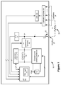
- FIG. 1 illustrates exemplary circuitry within a microstimulator 10.
- the illustrated microstimulator comprises a single-anode/multi-cathode design, but could also comprise a single-anode/single-cathode or multi-anode/multi-cathode design.
- Therapeutic stimulation occurs as follows.
- the anode electrode 27 sources a current, I, into a resistance 24, R, i.e., the user's tissue.
- the return path for the current is provided by one or more cathodes 28, which can be selected via cathode switches 30.
- the magnitude of the current I is specified by a Digital-to-Analog Converter, or DAC 32, whose circuitry and structure is explained in the above-incorporated references.
- DAC 32 Digital-to-Analog Converter
- a decoupling capacitor 22, C is disposed in the current path, usually proximate to the anode electrode 27.
- a decoupling capacitor 22 is useful in implantable stimulator devices to assist in charge recovery after the provision of a stimulation pulse, and to provide additional safety by preventing the direct injection of current to the patient's tissue 24.
- the microstimulator 10 contains a battery 12 to power its various logic circuits, and to produce the energy necessary to provide the desired stimulation pulses at the electrodes 27, 28.
- a battery 12 When producing stimulation pulses, it is generally necessary to generate a compliance voltage, V+, from the battery voltage, Vbat. This is because it is generally necessary to tailor the voltage needed to produce the desired therapeutic current, I, and such tailoring is especially necessary when one considers that the resistance 24 of the patient's tissue will be variable.
- Compliance voltage generation circuitry 18 generally boosts the battery voltage to a higher compliance voltage V+, and thus comprises a DC-to-DC converter. (The circuitry 18 can also generate a compliance voltage lower than the battery voltage should that be warranted).
- the compliance voltage generation circuitry 18 uses a coil 15 within the microstimulator. As will be seen below, the coil 15 has other uses in the microstimulator 10. However, as concerns compliance voltage generation, the inductance of the coil 15 is used in conjunction with the V+ generation circuitry 18 (usually including at least one capacitor and at least one diode) to produce a desired compliance voltage, V+.
- Exemplary V+ generation circuitry employing a coiled inductor to produce the compliance voltage in an implantable medical device is disclosed in U.S. Patent Application 2005/0131496, published June 16, 2005 , which is incorporated herein by reference in its entirety.
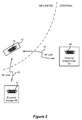
- the coil 15 can be used for other purposes within the microstimulator 10. As shown in Figure 2 , the coil 15 can also be used as a means for wirelessly receiving power from an external charger 40, and for wirelessly receiving data from an external programmer 45. These external devices are typically separate from each other, but could be integrated as well. As is well known, the external charger 40 is typically a hand-held device used to recharge the battery 12 within the microstimulator. (In other embodiments, the external charger 40 can also be used to continuously provide energy to an implant otherwise lacking a battery).
- the external programmer 45 is also typically hand held, and is used by a clinician or patient to send data to the microstimulator 10. For example, by manipulating a user interface (not shown) on the external programmer 45, a clinician can provide a therapy program tailored for a particular patient, which program might specify the amplitude, pulse width, and frequency of the stimulation pulses to be provided to the patient.
- These external devices also contain coils 41, 46, which are energized to create magnetic fields, which in turn induce currents in the coil 15 within the microstimulator 10.
- energy induced in coil 15 from coil 41 is rectified and passed via charging and battery protection circuitry 14 ( Fig. 1 ) to the battery 12, which allows the battery 12 to be safely charged to a value of about 4.1 V for example.
- coil 46 in the external programmer 45 is likewise energized, typically using a Frequency Shift Keying (FSK) modulation protocol.
- FSK Frequency Shift Keying
- Data telemetry can also occur in the other direction, i.e., from the coil 15 to the coil 46 to allow the microstimulator 10 to report to the external programmer 45 concerning its status, and in this regard the telemetry circuit 16 can comprise both transmitter and receiver circuitry.
- the coil 15 in the microstimulator 10 is implicated in compliance voltage generation, battery recharging, and telemetry.
- the use of one coil 15 to perform different functions in a microstimulator 10 is advantageous: space is limited within the housing of the microstimulator, which tends to limits the number of discrete coils that can be used. Accordingly, it is generally necessary for the microcontroller 20 in the microstimulator 10 to arbitrate or time-multiplex the use of the coil 15 so that the various functions will not be in conflict. For example, during charging, telemetry circuitry 16 and V+ generation circuitry 18 are typically disabled by the microcontroller 20, ensuring that the coil 15 will only be used to assist in recharging the microstimulator's battery 12.
- the telemetry circuitry 16 is enabled, and the coil 15 reserved for telemetry, during the listening window 52.
- the duration of the listening window 52 may be about 20 milliseconds (ms) or so, and ideally occurs periodically, T(t), every 100 ms or so. However, such periodicity is variable as explained below.
- Compliance voltage generation occurs during the provision of therapeutic stimulation to a patient.
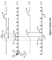
- An exemplary therapy of stimulation 60 is shown in Figure 3 .
- the stimulation 60 can be understood as an alternating sequence of pulses 62 and inter-pulse periods 64.
- the pulses 62 correspond to points in time in which the desired therapeutic current, I, is provided to patient.
- Such pulses 62 typically will not exceed a duration D(p) of 1 ms, and may be as low as 10 microseconds in duration.
- the inter-pulse period 64 Two primary events occur during the inter-pulse period 64 after each pulse 62.
- the compliance voltage for the next pulse is generated; this is generally necessary because the issuance of the pulse will have loaded the compliance voltage to below a level suitable for the next pulse.
- generation of the compliance voltage requires activation of the V+ generation circuitry 18, and access to the coil 15.
- the decoupling capacitor 22 (C) is discharged during the inter-pulse period 64. As disclosed in the above-mentioned 11/550,655 application, this typically occurs by coupling both the anode and the selected cathode(s) to the battery voltage, Vbat, which has the effect of shorting both sides of the decoupling capacitor 22 through the patient's tissue 24.
- the duration, D(r), of the inter-pulse period 64 is variable, and depends on the frequency, f(s), of the stimulation pulses chosen as effective for the patient.
- the inter-pulse period duration generally cannot be less than a certain minimum, which guarantees sufficient time to perform the necessary inter-pulse tasks of compliance voltage generation and output capacitor discharge.
- the reality of a minimum duration for the inter-pulse period in turns limits the maximum frequency f(s) that can be chosen for the stimulation timing signal 60, but such limit is normally beyond that required for useful therapy and hence does not substantially limit the utility of the microstimulator 10.
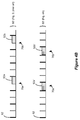
- FIG. 3 Illustrated are exemplary ideal timing signals for both telemetry listening (50) and for stimulation (60).
- the listening windows 52 are ideally set to a duration D(t) of 20 ms, and occur with a periodicity T(t) of 100 ms.
- the stimulation timing signal 60 in the example has been chosen with a pulse duration D(p) of 1 ms, and a frequency f(s) of 55.555 Hz. Working the math, this equates to an inter-pulse period duration D(r) of 17 ms, for a total stimulation period T(s) of 18 ms.
- arbitration logic 21 within the microcontroller 20 will cause both the telemetry listening timing signal (50) and the stimulation timing signal (60) to deviate from ideal values. This is because the arbitration logic 21 treats each stimulation cycle 65 (comprising a pulse 62 and an inter-pulse period 64) and each listening window 52 as blocks that cannot overlap in time. Therefore, the microcontroller 20, when arbitrating, will not grant priority to a listening window 52 until the currently-pending stimulation cycle 65 has completed. For example, in Figure 3 , the ideal timing of listening window 52a overlaps with the finishing of stimulation cycle 65a.
- listening window 52a' is made to wait until the close of stimulation cycle 65a, i.e., until the inter-pulse period 64 within that cycle has completed. Once the listening window 52a' has issued, it will need unencumbered access to the coil 15. Therefore, the next stimulation cycle 65b' cannot start until the end of the listening window 52a', as shown in non-ideal stimulation timing signal 60'.
- a non-ideal telemetry listening timing signal 50' and a non-ideal stimulation timing signal 60' result.
- the resulting non-ideal stimulation timing signal 60' is potentially problematic.
- the result of the arbitration scheme results in prolonged gaps 70a, 70b, etc. in the stimulation pulses 62. These gaps 70a are significantly longer (37 ms) than what was otherwise deemed as ideal therapy for the patient (17 ms), and occur with significant frequency (e.g., every sixth pulse in the example of Figure 3 ). Such gross deviations from the ideal may be perceptible by the patient, and hence are greatly disfavored.
- the implantable stimulator art and particularly the microstimulator art, would benefit from an improved technique to allow concurrent stimulation and telemetry listening that does not cause large deviations of the stimulation pulses from their ideal timings.
- An improved arbitration scheme for allowing concurrent stimulation and telemetry listening in a microstimulator or other implantable pulse generator is disclosed.
- a listening window for telemetry is permitted to proceed, and access to the microstimulator's coil granted, during at least a portion of the inter-pulse period that follows the issuance of a stimulation pulse. This is permissible because access to the coil is not needed during the entirety of the inter-pulse period.
- the listening window can issue during that portion of the inter-pulse period when the decoupling capacitor is discharged, because discharging of the decoupling capacitor des not require access to the coil.
- the listening window cannot issue during that portion of the inter-pulse period when the compliance voltage is being generated for the next stimulation pulse, because compliance voltage generation does require access to the coil.
- compliance voltage generation occurs relatively quickly and occupies only a small portion of the inter-pulse period, not being able to issue the listening window during that inter-pulse period portion does not significantly limit the technique.
- the listening window produces smaller gaps between the pulses. As a result, the stimulation pulses are issued at closer to their ideal positions, and the patient is less likely to perceive a difference from otherwise ideal therapy arising from the telemetry listening window.
- compliance voltage generation occurs relatively quickly during the inter-pulse period 64, whereas discharging of the decoupling capacitor 22 occurs relatively slowly.
- the duration of compliance voltage generation, D(g) typically occurs in under a millisecond.
- the duration necessary to discharge the decoupling capacitor, D(c) can take up to ten milliseconds or more.
- the decoupling capacitor discharge duration D(c) will be proportional to the product of the width and amplitude of the stimulation pulse, and thus will be variable, but regardless is typically at least five to ten times longer than the duration D(g) necessary for compliance voltage generation.
- the difference in these durations D(g) and D(c) is significant to the problem of interruption of the stimulation pulses 62 by the listening window 52, especially when one considers the impact on the coil 15.
- Decoupling capacitor discharge does not require coil 15 access. Therefore, the telemetry listening window 52 (where telemetry listening does require access to the coil) can be arbitrated to occur concurrently with decoupling capacitor discharge.
- compliance voltage generation does require access to the coil, the telemetry listening window 52 cannot be arbitrated to occur concurrently with compliance voltage generation.
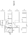
- the microcontroller 20 can allow the listening window 52 to issue after compliance voltage generation has finished (i.e., after duration D(g)), but concurrently with discharging of the decoupling capacitor.
- This is shown in the improved telemetry listening timing signal 50' of Figure 4A .
- the listening window 52' has been moved 53 from its ideal position (50) and into a portion of the inter-pulse period 64 such that it is issued after compliance voltage generation, D(g).
- the next stimulation pulse 62b' can issue after the listening window has completed.
- Figure 4A illustrates moving the listening window 52' to an earlier time
- arbitration in accordance with the disclosed technique could also move the listening window 52' later in time, such that it occurs after compliance voltage generation of the next pulse 62b, i.e., between pulses 62b and 62c.
- the disclosed technique when compared to an ideal inter-pulse period D(r) of 17 ms, the disclosed technique produces a gap 70 of 21 ms (D(g) + D(t)), compared to a gap 70 of 37 ms (D(r) + D(t)).
- the resulting stimulation timing signal 60' is thus much closer to the ideal 60 using the disclosed technique, and accordingly is less likely to be perceived by the patient.
- the listening window 52 has a relatively short duration D(t) compared to the duration D(r) of the inter-pulse period 64 in a given application
- use of the disclosed technique can eliminate an excessive gap 70 altogether, with the result that the resulting stimulation timing signal 60' is perfectly ideal. This would occur when the sum of the duration of compliance voltage generation D(g) plus the duration of the listening window D(t) is less or equal to than the duration of the needed inter-pulse period D(r) (i.e., when D(g) + D(t) ⁇ D(r)).
- the arbitration logic 21 can assess whether the microstimulator 10 is currently within an inter-pulse period 64, and if so, whether the compliance voltage V+ has been generated to a suitable level, e.g., whether D(g) has passed, or whether a certain magnitude for V+ has been reached. If so, the arbitration logic 21 can allow the listening window 52 to issue by enabling the telemetry circuitry 16 as appropriate in accordance with the technique disclosed herein.
- the disclosed technique can be used to improve the timing of any sort of periodically-issued telemetry window, even if that window's purpose is not to listen for telemetry from an external device.
- time-arbitrated telemetry windows can be used to periodically receive data from or transmit data to the external device, even while stimulation is occurring.
- programming data could be gradually received over a number of telemetry windows while stimulation pulses are being provided to the patient.
- the microstimulator could use the telemetry windows to periodically provide information concerning its status to the external device, again while stimulation pulses are being provided to the patient.
Landscapes
- Health & Medical Sciences (AREA)
- Engineering & Computer Science (AREA)
- Biomedical Technology (AREA)
- Nuclear Medicine, Radiotherapy & Molecular Imaging (AREA)
- Radiology & Medical Imaging (AREA)
- Life Sciences & Earth Sciences (AREA)
- Animal Behavior & Ethology (AREA)
- General Health & Medical Sciences (AREA)
- Public Health (AREA)
- Veterinary Medicine (AREA)
- Electrotherapy Devices (AREA)
Applications Claiming Priority (2)
| Application Number | Priority Date | Filing Date | Title |
|---|---|---|---|
| US11/776,170 US8131377B2 (en) | 2007-07-11 | 2007-07-11 | Telemetry listening window management for an implantable medical device |
| PCT/US2008/068079 WO2009009290A1 (en) | 2007-07-11 | 2008-06-25 | Telemetry listening window management for an implantable medical device |
Publications (2)
| Publication Number | Publication Date |
|---|---|
| EP2167189A1 EP2167189A1 (en) | 2010-03-31 |
| EP2167189B1 true EP2167189B1 (en) | 2016-07-20 |
Family
ID=39732811
Family Applications (1)
| Application Number | Title | Priority Date | Filing Date |
|---|---|---|---|
| EP08771858.1A Not-in-force EP2167189B1 (en) | 2007-07-11 | 2008-06-25 | Telemetry listening window management for an implantable medical device |
Country Status (6)
| Country | Link |
|---|---|
| US (1) | US8131377B2 (enExample) |
| EP (1) | EP2167189B1 (enExample) |
| JP (1) | JP5175345B2 (enExample) |
| CA (1) | CA2687227C (enExample) |
| ES (1) | ES2594202T3 (enExample) |
| WO (1) | WO2009009290A1 (enExample) |
Cited By (3)
| Publication number | Priority date | Publication date | Assignee | Title |
|---|---|---|---|---|
| US9564777B2 (en) | 2014-05-18 | 2017-02-07 | NeuSpera Medical Inc. | Wireless energy transfer system for an implantable medical device using a midfield coupler |
| US9610457B2 (en) | 2013-09-16 | 2017-04-04 | The Board Of Trustees Of The Leland Stanford Junior University | Multi-element coupler for generation of electromagnetic energy |
| US11338148B2 (en) | 2015-05-15 | 2022-05-24 | NeuSpera Medical Inc. | External power devices and systems |
Families Citing this family (33)
| Publication number | Priority date | Publication date | Assignee | Title |
|---|---|---|---|---|
| US8335569B2 (en) * | 2009-02-10 | 2012-12-18 | Boston Scientific Neuromodulation Corporation | External device for communicating with an implantable medical device having data telemetry and charging integrated in a single housing |
| US9233254B2 (en) | 2009-02-17 | 2016-01-12 | Boston Scientific Neuromodulation Corporation | Selectable boost converter and charge pump for compliance voltage generation in an implantable stimulator device |
| US8744592B2 (en) | 2009-10-08 | 2014-06-03 | Boston Scientific Neuromodulation Corporation | Efficient external charger for an implantable medical device optimized for fast charging and constrained by an implant power dissipation limit |
| WO2011097289A1 (en) | 2010-02-03 | 2011-08-11 | Medtronic, Inc. | Implantable medical devices and systems having dual frequency inductive telemetry and recharge |
| US9042995B2 (en) * | 2010-02-03 | 2015-05-26 | Medtronic, Inc. | Implantable medical devices and systems having power management for recharge sessions |
| US8788045B2 (en) | 2010-06-08 | 2014-07-22 | Bluewind Medical Ltd. | Tibial nerve stimulation |
| US9186504B2 (en) | 2010-11-15 | 2015-11-17 | Rainbow Medical Ltd | Sleep apnea treatment |
| US9457186B2 (en) | 2010-11-15 | 2016-10-04 | Bluewind Medical Ltd. | Bilateral feedback |
| US9136728B2 (en) | 2011-04-28 | 2015-09-15 | Medtronic, Inc. | Implantable medical devices and systems having inductive telemetry and recharge on a single coil |
| US20130123881A1 (en) * | 2011-11-11 | 2013-05-16 | Boston Scientific Neuromodulation Corporation | External Charger for an Implantable Medical Device System Having a Coil for Communication and Charging |
| US20150018728A1 (en) | 2012-01-26 | 2015-01-15 | Bluewind Medical Ltd. | Wireless neurostimulators |
| JP6070828B2 (ja) | 2012-04-27 | 2017-02-01 | ボストン サイエンティフィック ニューロモデュレイション コーポレイション | 埋込可能刺激デバイスでパルスを生成するためのタイミングチャネル回路 |
| US9174051B2 (en) | 2012-04-29 | 2015-11-03 | Boston Scientific Neuromodulation Corporation | Real time compliance voltage generation for an implantable stimulator |
| US9314632B2 (en) | 2012-05-17 | 2016-04-19 | Boston Scientific Neuromodulation Corporation | Pulse-by-pulse compliance voltage generation for an implantable stimulator |
| WO2014087337A1 (en) | 2012-12-06 | 2014-06-12 | Bluewind Medical Ltd. | Delivery of implantable neurostimulators |
| US9795788B2 (en) * | 2013-05-30 | 2017-10-24 | Pacesetter, Inc. | Implantable medical devices, and methods of use therewith, that use a same coil for receiving both communication and power signals |
| JP6078697B2 (ja) * | 2013-08-14 | 2017-02-08 | ボストン サイエンティフィック ニューロモデュレイション コーポレイション | 非充電式バッテリを有する埋込可能医療デバイスのための電力アーキテクチャ |
| US9764146B2 (en) | 2015-01-21 | 2017-09-19 | Bluewind Medical Ltd. | Extracorporeal implant controllers |
| US10004896B2 (en) | 2015-01-21 | 2018-06-26 | Bluewind Medical Ltd. | Anchors and implant devices |
| US9597521B2 (en) | 2015-01-21 | 2017-03-21 | Bluewind Medical Ltd. | Transmitting coils for neurostimulation |
| US9782589B2 (en) | 2015-06-10 | 2017-10-10 | Bluewind Medical Ltd. | Implantable electrostimulator for improving blood flow |
| US10105540B2 (en) | 2015-11-09 | 2018-10-23 | Bluewind Medical Ltd. | Optimization of application of current |
| US9713707B2 (en) | 2015-11-12 | 2017-07-25 | Bluewind Medical Ltd. | Inhibition of implant migration |
| EP3525874B1 (en) * | 2016-10-16 | 2021-09-22 | Stimaire, Inc. | Wireless neural stimulator with injectable element |
| US10124178B2 (en) | 2016-11-23 | 2018-11-13 | Bluewind Medical Ltd. | Implant and delivery tool therefor |
| US20180353764A1 (en) | 2017-06-13 | 2018-12-13 | Bluewind Medical Ltd. | Antenna configuration |
| US12383745B2 (en) | 2019-09-06 | 2025-08-12 | Boston Scientific Neuromodulation Corporation | Management of compliance voltage for a stimulator device |
| AU2021355509B2 (en) | 2020-09-30 | 2024-11-07 | Boston Scientific Neuromodulation Corporation | Adjustment of advertising interval in communications between an implantable medical device and an external device |
| EP4623988A3 (en) | 2020-09-30 | 2025-11-05 | Boston Scientific Neuromodulation Corporation | Programming of pairing and mri modes in an implantable medical device system |
| WO2022072973A1 (en) | 2020-09-30 | 2022-04-07 | Boston Scientific Neuromodulation Corporation | Pairing of external communication devices with an implantable medical device via a patient remote controller |
| AU2021382058B2 (en) | 2020-11-20 | 2025-01-02 | Boston Scientific Neuromodulation Corporation | Compliance voltage monitoring and adjustment in an implantable medical device using low side sensing |
| US11400299B1 (en) | 2021-09-14 | 2022-08-02 | Rainbow Medical Ltd. | Flexible antenna for stimulator |
| CN118217536B (zh) * | 2024-05-27 | 2024-08-09 | 苏州新云医疗设备有限公司 | 植入式神经刺激器及系统 |
Family Cites Families (27)
| Publication number | Priority date | Publication date | Assignee | Title |
|---|---|---|---|---|
| US5088488A (en) | 1989-12-22 | 1992-02-18 | Medtronic, Inc. | Method and apparatus for implementing histogram storage and trend analysis in a medical stimulator |
| US5314458A (en) | 1990-06-01 | 1994-05-24 | University Of Michigan | Single channel microstimulator |
| US5201865A (en) | 1991-10-28 | 1993-04-13 | Medtronic, Inc. | Medical lead impedance measurement system |
| US5309919A (en) | 1992-03-02 | 1994-05-10 | Siemens Pacesetter, Inc. | Method and system for recording, reporting, and displaying the distribution of pacing events over time and for using same to optimize programming |
| US5507786A (en) | 1994-04-14 | 1996-04-16 | Pacesetter, Inc. | System and method for measuring and storing parametric data pertaining to operating characteristics of an implantable medical device |
| US5766232A (en) | 1996-05-10 | 1998-06-16 | Medtronic, Inc. | Method and apparatus for altering the Q of an implantable medical device telemetry antenna |
| US5733312A (en) | 1997-01-17 | 1998-03-31 | Pacesetter, Inc. | System and method for modulating the output of an implantable medical device in response to circadian variations |
| US5978713A (en) | 1998-02-06 | 1999-11-02 | Intermedics Inc. | Implantable device with digital waveform telemetry |
| US9113801B2 (en) | 1998-08-05 | 2015-08-25 | Cyberonics, Inc. | Methods and systems for continuous EEG monitoring |
| US6516227B1 (en) | 1999-07-27 | 2003-02-04 | Advanced Bionics Corporation | Rechargeable spinal cord stimulator system |
| US6553263B1 (en) | 1999-07-30 | 2003-04-22 | Advanced Bionics Corporation | Implantable pulse generators using rechargeable zero-volt technology lithium-ion batteries |
| US6631296B1 (en) | 2000-03-17 | 2003-10-07 | Advanced Bionics Corporation | Voltage converter for implantable microstimulator using RF-powering coil |
| US6535766B1 (en) | 2000-08-26 | 2003-03-18 | Medtronic, Inc. | Implanted medical device telemetry using integrated microelectromechanical filtering |
| US6868288B2 (en) | 2000-08-26 | 2005-03-15 | Medtronic, Inc. | Implanted medical device telemetry using integrated thin film bulk acoustic resonator filtering |
| US6556871B2 (en) | 2001-01-04 | 2003-04-29 | Cardiac Pacemakers, Inc. | System and method for receiving telemetry data from an implantable medical device |
| US20040015205A1 (en) | 2002-06-20 | 2004-01-22 | Whitehurst Todd K. | Implantable microstimulators with programmable multielectrode configuration and uses thereof |
| US7428438B2 (en) | 2002-06-28 | 2008-09-23 | Boston Scientific Neuromodulation Corporation | Systems and methods for providing power to a battery in an implantable stimulator |
| US7437193B2 (en) | 2002-06-28 | 2008-10-14 | Boston Scientific Neuromodulation Corporation | Microstimulator employing improved recharging reporting and telemetry techniques |
| US20050075696A1 (en) | 2003-10-02 | 2005-04-07 | Medtronic, Inc. | Inductively rechargeable external energy source, charger, system and method for a transcutaneous inductive charger for an implantable medical device |
| AU2005254016A1 (en) | 2004-06-10 | 2005-12-29 | Ndi Medical, Llc | Systems and methods for bilateral stimulation of left and right branches of the dorsal genital nerves to treat dysfunctions, such as urinary incontinence |
| US9308382B2 (en) | 2004-06-10 | 2016-04-12 | Medtronic Urinary Solutions, Inc. | Implantable pulse generator systems and methods for providing functional and/or therapeutic stimulation of muscles and/or nerves and/or central nervous system tissue |
| WO2006022993A2 (en) | 2004-06-10 | 2006-03-02 | Ndi Medical, Llc | Implantable generator for muscle and nerve stimulation |
| US7702385B2 (en) | 2005-11-16 | 2010-04-20 | Boston Scientific Neuromodulation Corporation | Electrode contact configurations for an implantable stimulator |
| US7957805B2 (en) | 2005-06-01 | 2011-06-07 | Boston Scientific Neuromodulation Corporation | Implantable microstimulator with external electrodes disposed on a film substrate and methods of manufacture and use |
| US8010209B2 (en) | 2005-10-14 | 2011-08-30 | Nanostim, Inc. | Delivery system for implantable biostimulator |
| EP2029219B1 (en) | 2006-05-17 | 2013-10-16 | Medtronic Urinary Solutions, Inc. | Implantable pulse generator systems |
| US9480846B2 (en) | 2006-05-17 | 2016-11-01 | Medtronic Urinary Solutions, Inc. | Systems and methods for patient control of stimulation systems |
-
2007
- 2007-07-11 US US11/776,170 patent/US8131377B2/en not_active Expired - Fee Related
-
2008
- 2008-06-25 ES ES08771858.1T patent/ES2594202T3/es active Active
- 2008-06-25 JP JP2010516122A patent/JP5175345B2/ja not_active Expired - Fee Related
- 2008-06-25 EP EP08771858.1A patent/EP2167189B1/en not_active Not-in-force
- 2008-06-25 WO PCT/US2008/068079 patent/WO2009009290A1/en not_active Ceased
- 2008-06-25 CA CA2687227A patent/CA2687227C/en not_active Expired - Fee Related
Cited By (9)
| Publication number | Priority date | Publication date | Assignee | Title |
|---|---|---|---|---|
| US9610457B2 (en) | 2013-09-16 | 2017-04-04 | The Board Of Trustees Of The Leland Stanford Junior University | Multi-element coupler for generation of electromagnetic energy |
| US9662507B2 (en) | 2013-09-16 | 2017-05-30 | The Board Of Trustees Of The Leland Stanford Junior University | Multi-element coupler for generation of electromagnetic energy |
| US9687664B2 (en) | 2013-09-16 | 2017-06-27 | The Board Of Trustees Of The Leland Stanford Junior University | Multi-element coupler for generation of electromagnetic energy |
| US9744369B2 (en) | 2013-09-16 | 2017-08-29 | The Board Of Trustees Of The Leland Stanford Junior University | Multi-element coupler for generation of electromagnetic energy |
| US10039924B2 (en) | 2013-09-16 | 2018-08-07 | The Board Of Trustees Of The Leland Stanford Junior University | Wireless midfield systems and methods |
| US9564777B2 (en) | 2014-05-18 | 2017-02-07 | NeuSpera Medical Inc. | Wireless energy transfer system for an implantable medical device using a midfield coupler |
| US9583980B2 (en) | 2014-05-18 | 2017-02-28 | NeuSpera Medical Inc. | Midfield coupler |
| US12176725B2 (en) | 2014-05-18 | 2024-12-24 | NeuSpera Medical Inc. | External power devices and systems |
| US11338148B2 (en) | 2015-05-15 | 2022-05-24 | NeuSpera Medical Inc. | External power devices and systems |
Also Published As
| Publication number | Publication date |
|---|---|
| JP5175345B2 (ja) | 2013-04-03 |
| EP2167189A1 (en) | 2010-03-31 |
| US20090018618A1 (en) | 2009-01-15 |
| JP2010532700A (ja) | 2010-10-14 |
| CA2687227C (en) | 2014-04-15 |
| CA2687227A1 (en) | 2009-01-15 |
| WO2009009290A1 (en) | 2009-01-15 |
| ES2594202T3 (es) | 2016-12-16 |
| US8131377B2 (en) | 2012-03-06 |
Similar Documents
| Publication | Publication Date | Title |
|---|---|---|
| EP2167189B1 (en) | Telemetry listening window management for an implantable medical device | |
| US10518089B2 (en) | Reversing recruitment order by anode intensification | |
| EP2866888B1 (en) | System for compounding low-frequency sources for high-frequency neuromodulation | |
| US9913987B2 (en) | Spatially selective nerve stimulation in high-frequency nerve conduction block and recruitment | |
| US10507328B2 (en) | Neuromodulation using modulated pulse train | |
| EP2968932B1 (en) | Neuromodulation system for providing multiple modulation patterns in a single channel | |
| EP2958618B1 (en) | Multi-channel neuromodulation system with means for combining pulse trains | |
| EP2586490B1 (en) | Stimulation system to control neural recruitment order and clinical effect | |
| US8812128B2 (en) | Implantable neurostimulator-initiated status notification | |
| AU2013282405B2 (en) | High frequency neuromodulation system for reducing energy requirements | |
| US20140031908A1 (en) | System and method for enhancing large diameter nerve fiber stimulation using sequential activation of electrodes |
Legal Events
| Date | Code | Title | Description |
|---|---|---|---|
| PUAI | Public reference made under article 153(3) epc to a published international application that has entered the european phase |
Free format text: ORIGINAL CODE: 0009012 |
|
| 17P | Request for examination filed |
Effective date: 20100112 |
|
| AK | Designated contracting states |
Kind code of ref document: A1 Designated state(s): AT BE BG CH CY CZ DE DK EE ES FI FR GB GR HR HU IE IS IT LI LT LU LV MC MT NL NO PL PT RO SE SI SK TR |
|
| AX | Request for extension of the european patent |
Extension state: AL BA MK RS |
|
| DAX | Request for extension of the european patent (deleted) | ||
| 17Q | First examination report despatched |
Effective date: 20101210 |
|
| GRAP | Despatch of communication of intention to grant a patent |
Free format text: ORIGINAL CODE: EPIDOSNIGR1 |
|
| INTG | Intention to grant announced |
Effective date: 20150804 |
|
| GRAS | Grant fee paid |
Free format text: ORIGINAL CODE: EPIDOSNIGR3 |
|
| INTG | Intention to grant announced |
Effective date: 20160126 |
|
| GRAA | (expected) grant |
Free format text: ORIGINAL CODE: 0009210 |
|
| AK | Designated contracting states |
Kind code of ref document: B1 Designated state(s): AT BE BG CH CY CZ DE DK EE ES FI FR GB GR HR HU IE IS IT LI LT LU LV MC MT NL NO PL PT RO SE SI SK TR |
|
| REG | Reference to a national code |
Ref country code: GB Ref legal event code: FG4D |
|
| REG | Reference to a national code |
Ref country code: CH Ref legal event code: EP |
|
| REG | Reference to a national code |
Ref country code: IE Ref legal event code: FG4D |
|
| REG | Reference to a national code |
Ref country code: AT Ref legal event code: REF Ref document number: 813550 Country of ref document: AT Kind code of ref document: T Effective date: 20160815 |
|
| REG | Reference to a national code |
Ref country code: DE Ref legal event code: R096 Ref document number: 602008045207 Country of ref document: DE |
|
| REG | Reference to a national code |
Ref country code: NL Ref legal event code: FP |
|
| REG | Reference to a national code |
Ref country code: LT Ref legal event code: MG4D |
|
| REG | Reference to a national code |
Ref country code: AT Ref legal event code: MK05 Ref document number: 813550 Country of ref document: AT Kind code of ref document: T Effective date: 20160720 |
|
| REG | Reference to a national code |
Ref country code: ES Ref legal event code: FG2A Ref document number: 2594202 Country of ref document: ES Kind code of ref document: T3 Effective date: 20161216 |
|
| PG25 | Lapsed in a contracting state [announced via postgrant information from national office to epo] |
Ref country code: HR Free format text: LAPSE BECAUSE OF FAILURE TO SUBMIT A TRANSLATION OF THE DESCRIPTION OR TO PAY THE FEE WITHIN THE PRESCRIBED TIME-LIMIT Effective date: 20160720 Ref country code: IS Free format text: LAPSE BECAUSE OF FAILURE TO SUBMIT A TRANSLATION OF THE DESCRIPTION OR TO PAY THE FEE WITHIN THE PRESCRIBED TIME-LIMIT Effective date: 20161120 Ref country code: LT Free format text: LAPSE BECAUSE OF FAILURE TO SUBMIT A TRANSLATION OF THE DESCRIPTION OR TO PAY THE FEE WITHIN THE PRESCRIBED TIME-LIMIT Effective date: 20160720 Ref country code: IT Free format text: LAPSE BECAUSE OF FAILURE TO SUBMIT A TRANSLATION OF THE DESCRIPTION OR TO PAY THE FEE WITHIN THE PRESCRIBED TIME-LIMIT Effective date: 20160720 Ref country code: FI Free format text: LAPSE BECAUSE OF FAILURE TO SUBMIT A TRANSLATION OF THE DESCRIPTION OR TO PAY THE FEE WITHIN THE PRESCRIBED TIME-LIMIT Effective date: 20160720 Ref country code: NO Free format text: LAPSE BECAUSE OF FAILURE TO SUBMIT A TRANSLATION OF THE DESCRIPTION OR TO PAY THE FEE WITHIN THE PRESCRIBED TIME-LIMIT Effective date: 20161020 |
|
| PG25 | Lapsed in a contracting state [announced via postgrant information from national office to epo] |
Ref country code: PT Free format text: LAPSE BECAUSE OF FAILURE TO SUBMIT A TRANSLATION OF THE DESCRIPTION OR TO PAY THE FEE WITHIN THE PRESCRIBED TIME-LIMIT Effective date: 20161121 Ref country code: AT Free format text: LAPSE BECAUSE OF FAILURE TO SUBMIT A TRANSLATION OF THE DESCRIPTION OR TO PAY THE FEE WITHIN THE PRESCRIBED TIME-LIMIT Effective date: 20160720 Ref country code: GR Free format text: LAPSE BECAUSE OF FAILURE TO SUBMIT A TRANSLATION OF THE DESCRIPTION OR TO PAY THE FEE WITHIN THE PRESCRIBED TIME-LIMIT Effective date: 20161021 Ref country code: SE Free format text: LAPSE BECAUSE OF FAILURE TO SUBMIT A TRANSLATION OF THE DESCRIPTION OR TO PAY THE FEE WITHIN THE PRESCRIBED TIME-LIMIT Effective date: 20160720 Ref country code: BE Free format text: LAPSE BECAUSE OF FAILURE TO SUBMIT A TRANSLATION OF THE DESCRIPTION OR TO PAY THE FEE WITHIN THE PRESCRIBED TIME-LIMIT Effective date: 20160720 Ref country code: PL Free format text: LAPSE BECAUSE OF FAILURE TO SUBMIT A TRANSLATION OF THE DESCRIPTION OR TO PAY THE FEE WITHIN THE PRESCRIBED TIME-LIMIT Effective date: 20160720 Ref country code: LV Free format text: LAPSE BECAUSE OF FAILURE TO SUBMIT A TRANSLATION OF THE DESCRIPTION OR TO PAY THE FEE WITHIN THE PRESCRIBED TIME-LIMIT Effective date: 20160720 |
|
| REG | Reference to a national code |
Ref country code: DE Ref legal event code: R097 Ref document number: 602008045207 Country of ref document: DE |
|
| PG25 | Lapsed in a contracting state [announced via postgrant information from national office to epo] |
Ref country code: EE Free format text: LAPSE BECAUSE OF FAILURE TO SUBMIT A TRANSLATION OF THE DESCRIPTION OR TO PAY THE FEE WITHIN THE PRESCRIBED TIME-LIMIT Effective date: 20160720 Ref country code: RO Free format text: LAPSE BECAUSE OF FAILURE TO SUBMIT A TRANSLATION OF THE DESCRIPTION OR TO PAY THE FEE WITHIN THE PRESCRIBED TIME-LIMIT Effective date: 20160720 |
|
| REG | Reference to a national code |
Ref country code: FR Ref legal event code: PLFP Year of fee payment: 10 |
|
| PLBE | No opposition filed within time limit |
Free format text: ORIGINAL CODE: 0009261 |
|
| STAA | Information on the status of an ep patent application or granted ep patent |
Free format text: STATUS: NO OPPOSITION FILED WITHIN TIME LIMIT |
|
| PG25 | Lapsed in a contracting state [announced via postgrant information from national office to epo] |
Ref country code: SK Free format text: LAPSE BECAUSE OF FAILURE TO SUBMIT A TRANSLATION OF THE DESCRIPTION OR TO PAY THE FEE WITHIN THE PRESCRIBED TIME-LIMIT Effective date: 20160720 Ref country code: DK Free format text: LAPSE BECAUSE OF FAILURE TO SUBMIT A TRANSLATION OF THE DESCRIPTION OR TO PAY THE FEE WITHIN THE PRESCRIBED TIME-LIMIT Effective date: 20160720 Ref country code: CZ Free format text: LAPSE BECAUSE OF FAILURE TO SUBMIT A TRANSLATION OF THE DESCRIPTION OR TO PAY THE FEE WITHIN THE PRESCRIBED TIME-LIMIT Effective date: 20160720 Ref country code: BG Free format text: LAPSE BECAUSE OF FAILURE TO SUBMIT A TRANSLATION OF THE DESCRIPTION OR TO PAY THE FEE WITHIN THE PRESCRIBED TIME-LIMIT Effective date: 20161020 |
|
| 26N | No opposition filed |
Effective date: 20170421 |
|
| PGFP | Annual fee paid to national office [announced via postgrant information from national office to epo] |
Ref country code: FR Payment date: 20170511 Year of fee payment: 10 |
|
| PG25 | Lapsed in a contracting state [announced via postgrant information from national office to epo] |
Ref country code: SI Free format text: LAPSE BECAUSE OF FAILURE TO SUBMIT A TRANSLATION OF THE DESCRIPTION OR TO PAY THE FEE WITHIN THE PRESCRIBED TIME-LIMIT Effective date: 20160720 |
|
| PGFP | Annual fee paid to national office [announced via postgrant information from national office to epo] |
Ref country code: ES Payment date: 20170704 Year of fee payment: 10 |
|
| PG25 | Lapsed in a contracting state [announced via postgrant information from national office to epo] |
Ref country code: MC Free format text: LAPSE BECAUSE OF FAILURE TO SUBMIT A TRANSLATION OF THE DESCRIPTION OR TO PAY THE FEE WITHIN THE PRESCRIBED TIME-LIMIT Effective date: 20160720 |
|
| REG | Reference to a national code |
Ref country code: CH Ref legal event code: PL |
|
| GBPC | Gb: european patent ceased through non-payment of renewal fee |
Effective date: 20170625 |
|
| PG25 | Lapsed in a contracting state [announced via postgrant information from national office to epo] |
Ref country code: LI Free format text: LAPSE BECAUSE OF NON-PAYMENT OF DUE FEES Effective date: 20170630 Ref country code: CH Free format text: LAPSE BECAUSE OF NON-PAYMENT OF DUE FEES Effective date: 20170630 Ref country code: LU Free format text: LAPSE BECAUSE OF NON-PAYMENT OF DUE FEES Effective date: 20170625 Ref country code: GB Free format text: LAPSE BECAUSE OF NON-PAYMENT OF DUE FEES Effective date: 20170625 |
|
| PG25 | Lapsed in a contracting state [announced via postgrant information from national office to epo] |
Ref country code: MT Free format text: LAPSE BECAUSE OF NON-PAYMENT OF DUE FEES Effective date: 20170625 |
|
| PG25 | Lapsed in a contracting state [announced via postgrant information from national office to epo] |
Ref country code: FR Free format text: LAPSE BECAUSE OF NON-PAYMENT OF DUE FEES Effective date: 20180630 |
|
| PG25 | Lapsed in a contracting state [announced via postgrant information from national office to epo] |
Ref country code: HU Free format text: LAPSE BECAUSE OF FAILURE TO SUBMIT A TRANSLATION OF THE DESCRIPTION OR TO PAY THE FEE WITHIN THE PRESCRIBED TIME-LIMIT; INVALID AB INITIO Effective date: 20080625 |
|
| REG | Reference to a national code |
Ref country code: ES Ref legal event code: FD2A Effective date: 20190916 |
|
| PG25 | Lapsed in a contracting state [announced via postgrant information from national office to epo] |
Ref country code: ES Free format text: LAPSE BECAUSE OF NON-PAYMENT OF DUE FEES Effective date: 20180626 Ref country code: CY Free format text: LAPSE BECAUSE OF NON-PAYMENT OF DUE FEES Effective date: 20160720 |
|
| PG25 | Lapsed in a contracting state [announced via postgrant information from national office to epo] |
Ref country code: TR Free format text: LAPSE BECAUSE OF FAILURE TO SUBMIT A TRANSLATION OF THE DESCRIPTION OR TO PAY THE FEE WITHIN THE PRESCRIBED TIME-LIMIT Effective date: 20160720 |
|
| PGFP | Annual fee paid to national office [announced via postgrant information from national office to epo] |
Ref country code: IE Payment date: 20200609 Year of fee payment: 13 Ref country code: DE Payment date: 20200609 Year of fee payment: 13 |
|
| PGFP | Annual fee paid to national office [announced via postgrant information from national office to epo] |
Ref country code: NL Payment date: 20200615 Year of fee payment: 13 |
|
| REG | Reference to a national code |
Ref country code: DE Ref legal event code: R119 Ref document number: 602008045207 Country of ref document: DE |
|
| REG | Reference to a national code |
Ref country code: NL Ref legal event code: MM Effective date: 20210701 |
|
| PG25 | Lapsed in a contracting state [announced via postgrant information from national office to epo] |
Ref country code: IE Free format text: LAPSE BECAUSE OF NON-PAYMENT OF DUE FEES Effective date: 20210625 Ref country code: DE Free format text: LAPSE BECAUSE OF NON-PAYMENT OF DUE FEES Effective date: 20220101 |
|
| PG25 | Lapsed in a contracting state [announced via postgrant information from national office to epo] |
Ref country code: NL Free format text: LAPSE BECAUSE OF NON-PAYMENT OF DUE FEES Effective date: 20210701 |