EP2166640A2 - A Power transmission control device, a power transmission device, a power receiving control device, a power receiving device, an electronic apparatus, a method for controlling power transmission, and a method for controlling power receiving - Google Patents
A Power transmission control device, a power transmission device, a power receiving control device, a power receiving device, an electronic apparatus, a method for controlling power transmission, and a method for controlling power receiving Download PDFInfo
- Publication number
- EP2166640A2 EP2166640A2 EP09163764A EP09163764A EP2166640A2 EP 2166640 A2 EP2166640 A2 EP 2166640A2 EP 09163764 A EP09163764 A EP 09163764A EP 09163764 A EP09163764 A EP 09163764A EP 2166640 A2 EP2166640 A2 EP 2166640A2
- Authority
- EP
- European Patent Office
- Prior art keywords
- power transmission
- power
- power receiving
- information
- control device
- Prior art date
- Legal status (The legal status is an assumption and is not a legal conclusion. Google has not performed a legal analysis and makes no representation as to the accuracy of the status listed.)
- Granted
Links
Images


Classifications
-
- H—ELECTRICITY
- H02—GENERATION; CONVERSION OR DISTRIBUTION OF ELECTRIC POWER
- H02J—CIRCUIT ARRANGEMENTS OR SYSTEMS FOR SUPPLYING OR DISTRIBUTING ELECTRIC POWER; SYSTEMS FOR STORING ELECTRIC ENERGY
- H02J13/00—Circuit arrangements for providing remote indication of network conditions, e.g. an instantaneous record of the open or closed condition of each circuitbreaker in the network; Circuit arrangements for providing remote control of switching means in a power distribution network, e.g. switching in and out of current consumers by using a pulse code signal carried by the network
- H02J13/00006—Circuit arrangements for providing remote indication of network conditions, e.g. an instantaneous record of the open or closed condition of each circuitbreaker in the network; Circuit arrangements for providing remote control of switching means in a power distribution network, e.g. switching in and out of current consumers by using a pulse code signal carried by the network characterised by information or instructions transport means between the monitoring, controlling or managing units and monitored, controlled or operated power network element or electrical equipment
-
- H—ELECTRICITY
- H02—GENERATION; CONVERSION OR DISTRIBUTION OF ELECTRIC POWER
- H02J—CIRCUIT ARRANGEMENTS OR SYSTEMS FOR SUPPLYING OR DISTRIBUTING ELECTRIC POWER; SYSTEMS FOR STORING ELECTRIC ENERGY
- H02J7/00—Circuit arrangements for charging or depolarising batteries or for supplying loads from batteries
- H02J7/00032—Circuit arrangements for charging or depolarising batteries or for supplying loads from batteries characterised by data exchange
- H02J7/00034—Charger exchanging data with an electronic device, i.e. telephone, whose internal battery is under charge
-
- H—ELECTRICITY
- H02—GENERATION; CONVERSION OR DISTRIBUTION OF ELECTRIC POWER
- H02J—CIRCUIT ARRANGEMENTS OR SYSTEMS FOR SUPPLYING OR DISTRIBUTING ELECTRIC POWER; SYSTEMS FOR STORING ELECTRIC ENERGY
- H02J1/00—Circuit arrangements for dc mains or dc distribution networks
- H02J1/08—Three-wire systems; Systems having more than three wires
- H02J1/084—Three-wire systems; Systems having more than three wires for selectively connecting the load or loads to one or several among a plurality of power lines or power sources
-
- H—ELECTRICITY
- H02—GENERATION; CONVERSION OR DISTRIBUTION OF ELECTRIC POWER
- H02J—CIRCUIT ARRANGEMENTS OR SYSTEMS FOR SUPPLYING OR DISTRIBUTING ELECTRIC POWER; SYSTEMS FOR STORING ELECTRIC ENERGY
- H02J13/00—Circuit arrangements for providing remote indication of network conditions, e.g. an instantaneous record of the open or closed condition of each circuitbreaker in the network; Circuit arrangements for providing remote control of switching means in a power distribution network, e.g. switching in and out of current consumers by using a pulse code signal carried by the network
- H02J13/00001—Circuit arrangements for providing remote indication of network conditions, e.g. an instantaneous record of the open or closed condition of each circuitbreaker in the network; Circuit arrangements for providing remote control of switching means in a power distribution network, e.g. switching in and out of current consumers by using a pulse code signal carried by the network characterised by the display of information or by user interaction, e.g. supervisory control and data acquisition systems [SCADA] or graphical user interfaces [GUI]
-
- H—ELECTRICITY
- H02—GENERATION; CONVERSION OR DISTRIBUTION OF ELECTRIC POWER
- H02J—CIRCUIT ARRANGEMENTS OR SYSTEMS FOR SUPPLYING OR DISTRIBUTING ELECTRIC POWER; SYSTEMS FOR STORING ELECTRIC ENERGY
- H02J50/00—Circuit arrangements or systems for wireless supply or distribution of electric power
- H02J50/10—Circuit arrangements or systems for wireless supply or distribution of electric power using inductive coupling
- H02J50/12—Circuit arrangements or systems for wireless supply or distribution of electric power using inductive coupling of the resonant type
-
- H—ELECTRICITY
- H02—GENERATION; CONVERSION OR DISTRIBUTION OF ELECTRIC POWER
- H02J—CIRCUIT ARRANGEMENTS OR SYSTEMS FOR SUPPLYING OR DISTRIBUTING ELECTRIC POWER; SYSTEMS FOR STORING ELECTRIC ENERGY
- H02J50/00—Circuit arrangements or systems for wireless supply or distribution of electric power
- H02J50/60—Circuit arrangements or systems for wireless supply or distribution of electric power responsive to the presence of foreign objects, e.g. detection of living beings
-
- H—ELECTRICITY
- H02—GENERATION; CONVERSION OR DISTRIBUTION OF ELECTRIC POWER
- H02J—CIRCUIT ARRANGEMENTS OR SYSTEMS FOR SUPPLYING OR DISTRIBUTING ELECTRIC POWER; SYSTEMS FOR STORING ELECTRIC ENERGY
- H02J50/00—Circuit arrangements or systems for wireless supply or distribution of electric power
- H02J50/80—Circuit arrangements or systems for wireless supply or distribution of electric power involving the exchange of data, concerning supply or distribution of electric power, between transmitting devices and receiving devices
-
- H—ELECTRICITY
- H02—GENERATION; CONVERSION OR DISTRIBUTION OF ELECTRIC POWER
- H02J—CIRCUIT ARRANGEMENTS OR SYSTEMS FOR SUPPLYING OR DISTRIBUTING ELECTRIC POWER; SYSTEMS FOR STORING ELECTRIC ENERGY
- H02J2213/00—Indexing scheme relating to details of circuit arrangements for providing remote indication of network conditions of for circuit arrangements for providing remote control of switching means in a power distribution network
- H02J2213/10—Indexing scheme relating to details of circuit arrangements for providing remote indication of network conditions of for circuit arrangements for providing remote control of switching means in a power distribution network using simultaneously two or more different transmission means
-
- H—ELECTRICITY
- H02—GENERATION; CONVERSION OR DISTRIBUTION OF ELECTRIC POWER
- H02J—CIRCUIT ARRANGEMENTS OR SYSTEMS FOR SUPPLYING OR DISTRIBUTING ELECTRIC POWER; SYSTEMS FOR STORING ELECTRIC ENERGY
- H02J9/00—Circuit arrangements for emergency or stand-by power supply, e.g. for emergency lighting
- H02J9/005—Circuit arrangements for emergency or stand-by power supply, e.g. for emergency lighting using a power saving mode
-
- Y—GENERAL TAGGING OF NEW TECHNOLOGICAL DEVELOPMENTS; GENERAL TAGGING OF CROSS-SECTIONAL TECHNOLOGIES SPANNING OVER SEVERAL SECTIONS OF THE IPC; TECHNICAL SUBJECTS COVERED BY FORMER USPC CROSS-REFERENCE ART COLLECTIONS [XRACs] AND DIGESTS
- Y02—TECHNOLOGIES OR APPLICATIONS FOR MITIGATION OR ADAPTATION AGAINST CLIMATE CHANGE
- Y02B—CLIMATE CHANGE MITIGATION TECHNOLOGIES RELATED TO BUILDINGS, e.g. HOUSING, HOUSE APPLIANCES OR RELATED END-USER APPLICATIONS
- Y02B90/00—Enabling technologies or technologies with a potential or indirect contribution to GHG emissions mitigation
- Y02B90/20—Smart grids as enabling technology in buildings sector
-
- Y—GENERAL TAGGING OF NEW TECHNOLOGICAL DEVELOPMENTS; GENERAL TAGGING OF CROSS-SECTIONAL TECHNOLOGIES SPANNING OVER SEVERAL SECTIONS OF THE IPC; TECHNICAL SUBJECTS COVERED BY FORMER USPC CROSS-REFERENCE ART COLLECTIONS [XRACs] AND DIGESTS
- Y04—INFORMATION OR COMMUNICATION TECHNOLOGIES HAVING AN IMPACT ON OTHER TECHNOLOGY AREAS
- Y04S—SYSTEMS INTEGRATING TECHNOLOGIES RELATED TO POWER NETWORK OPERATION, COMMUNICATION OR INFORMATION TECHNOLOGIES FOR IMPROVING THE ELECTRICAL POWER GENERATION, TRANSMISSION, DISTRIBUTION, MANAGEMENT OR USAGE, i.e. SMART GRIDS
- Y04S40/00—Systems for electrical power generation, transmission, distribution or end-user application management characterised by the use of communication or information technologies, or communication or information technology specific aspects supporting them
- Y04S40/12—Systems for electrical power generation, transmission, distribution or end-user application management characterised by the use of communication or information technologies, or communication or information technology specific aspects supporting them characterised by data transport means between the monitoring, controlling or managing units and monitored, controlled or operated electrical equipment
Definitions
- the present invention relates to contactless power transmission.
- the present invention relates to a power transmission control device, a power transmission device, a power receiving control device, a power receiving device, an electronic apparatus, a method for controlling contactless power transmission, and a method for controlling contactless power receiving.
- contactless power transmission non-contact power transmission
- contactless power transmission it is possible to perform transmission of electric power by utilizing electromagnetic induction without using a metallic contact.
- charging cell phones and household equipment e.g., cordless handsets of telephones
- JP-A-2006-60909 is a first example of related art of the contactless power transmission.
- an ID authentication is realized by transmitting and receiving an authentication code between a power receiving device (on a secondary side) and a power transmission device (on a primary side) so as to detect insertion of a foreign object.
- JP-A-10-94199 is a second example of related art.
- a power supply control system is disclosed such that in order to prevent a circuit breaker from tripping in a case where electrical appliances are simultaneously used at home, power usage information of the electrical appliances is gathered so as to determine whether or not power can be supplied within the acceptable range. Then, the power consumption is allowed to the electrical appliance that is determined to be eligible for the power consumption
- the power transmission device does not determine whether or not the coil ID received from the power receiving device is appropriate. Therefore, in a case where a plurality of the power receiving devices exists simultaneously, appropriate contactless power transmission from a power transmission device cannot be realized.
- the power transmission device since the power transmission device does not determine whether or not the coil ID received from the power receiving device is appropriate, functions and the like of the power receiving device are not determined. As a result, appropriate contactless power transmission cannot be realized.
- An advantage of the invention is to provide a power transmission control device, a power transmission device, a power receiving control device, a power receiving device, an electronic apparatus, a method for controlling power transmission, and a method for controlling power receiving that are capable of realizing an appropriate and efficient process sequence for contactless power transmission between the power transmission device and the power receiving device.
- a power transmission control device included in a contactless power transmission system for transmitting power by electromagnetically coupling a primary coil and a secondary coil from a power transmission device to a power receiving device so as to supply the power to a load of the power receiving device includes a controller for controlling the power transmission device.
- the controller includes: a negotiation processing section for performing a negotiation process of contactless power transmission; and a setup processing section for performing a setup process of the contactless power transmission based on a result of the negotiation process.
- normal power transmission from the power transmission device to the power receiving device is started after the setup process.
- the negotiation process of the contactless power transmission is performed so that various settings are made. Thereafter, the setup process is performed based on a result of the negotiation process so that various setups are made. Then, the normal power transmission from the power transmission device to the power receiving device is started. Accordingly, the minimum basic setting for realizing appropriate contactless power transmission is made in the negotiation process, and the setup of different setup information for each application is made in the setup process.
- the power transmission control device that is capable of realizing an appropriate and efficient process sequence can be provided.
- the controller may preferably further include a command processing section for performing a command process of the contactless power transmission after the setup process; and the normal power transmission from the power transmission device to the power receiving device is preferably started in the command process.
- the command processing section may preferably process a command for starting normal power transmission after the setup process.
- the command processing section may preferably process a command for detecting a full charge of a battery included in the load of the power receiving device or a command for confirming a recharge of the battery after the setup process.
- the negotiation process section may preferably perform a confirmation process for confirming whether or not information can be communicated with the power receiving device, and/or a confirmation process for confirming whether or not communicated information is adequate.
- the negotiation processing section may preferably perform a confirmation process for confirming whether or not the load of the power receiving device is appropriate.
- the load of the power receiving device can be confirmed before the setup process.
- the negotiation processing section may preferably perform a checking process for checking standard information, coil information, and/or system information with the power receiving device.
- the system information preferably indicates a method for detecting a load condition.
- various processes can be performed based on a result of the checking process of standard information, coil information, and/or system information of the power receiving side and that of the power transmission side.
- a transmission condition of the contactless power transmission may preferably be set in the setup processing section based on a result of the negotiation process.
- the setup process section may preferably receive the transmission condition information so as to set a transmission condition of the contactless power transmission.
- a transmission condition of the contactless power transmission can be set based on the transmission condition information from the power receiving side, in various combinations of the primary side and the secondary side, an appropriate transmission condition can be set.
- information on a corresponding function may be preferably exchanged in the setup process.
- the controller may preferably stop the normal power transmission if the power receiving device requests a power transmission stop.
- the normal power transmission is stopped if the power receiving device requests the power transmission stop.
- the controller may preferably stop the normal power transmission if a full charge of a battery included in the load of the power receiving device is detected.
- the controller may preferably move into a standby phase after detecting the full charge if the normal power transmission is stopped after detecting the full charge.
- the power transmission side can be moved into the standby phase after detecting the full charge.
- the controller may preferably be configured to confirm a recharge of the battery in the standby phase after detecting the full charge.
- a recharge of the battery can be confirmed when it is needed again in a period after detecting the full charge.
- the controller may preferably maintain a flag for confirming a recharge in a set state without clearing the flag in the standby phase after detecting the full charge.
- the command for confirming a recharge can be executed by the flag for confirming a recharge maintained in the set state.
- the controller may preferably move into a standby phase after detecting the removal.
- the controller may preferably move into a standby phase after detecting the removal, wherein the controller is preferably in the standby phase until the electronic apparatus of the power receiving device is placed or placed again.
- the controller may preferably move into a phase of the negotiation process.
- the normal power transmission can be started after going through the negotiation process and the setup process and the like.
- a power transmission device includes: the power transmission control device of the first aspect; and a power transmission section that generates an alternate current voltage so as to supply the voltage to the primary coil.
- an electronic apparatus includes: the power transmission device according to the second aspect.
- a power receiving control device included in a contactless power transmission system for transmitting power by electromagnetically coupling a primary coil and a secondary coil from a power transmission device to a power receiving device so as to supply the power to a load of the power receiving device includes a controller for controlling the power receiving device.
- the controller includes: a negotiation processing section for performing a negotiation process of contactless power transmission; and a setup processing section for performing a setup process of the contactless power transmission based on a result of the negotiation process.
- the negotiation process of the contactless power transmission is performed so that various settings are made. Thereafter, the setup process is performed based on a result of the negotiation process so that various setups are made. Then, power supply to the load is started. Accordingly, the minimum basic setting for realizing appropriate contactless power transmission is made in the negotiation process, and the setup of the different setup information for each application is made in the setup process.
- the power receiving control device that is capable of realizing an appropriate and efficient process sequence can be provided.
- the controller may preferably further include a command processing section for performing a command process of the contactless power transmission after the setup process.
- the power supply to the load is preferably started if the normal transmission from the power transmission device to the power receiving device is started in the command process.
- the command processing section may preferably process a command for starting normal power transmission after the setup process.
- the command processing section may preferably process the command for detecting a full charge of a battery included in the load of the power receiving device or the command for confirming a recharge of the battery.
- the negotiation process section may preferably perform a confirmation process for confirming whether or not information can be communicated with the power receiving device, and/or a confirmation process for confirming whether or not communicated information is adequate.
- the negotiation processing section may preferably perform a checking process for checking standard information, coil information, and/or system information with the power transmission device.
- the system information preferably indicates a method for detecting a load condition.
- various processes can be performed based on a result of the checking process of standard information, coil information and/or system information of the power receiving side and that of the power transmission side.
- transmission condition information of the contactless power transmission may be preferably transmitted in the setup processing section based on a result of the negotiation process.
- the different power transmission conditions for each apparatus and the like are set in the setup process so as to perform contactless power transmission.
- information on a corresponding function may be preferably exchanged in the setup process.
- a power receiving device includes: the power receiving control device according to the fourth aspect; and a power receiving section for converting an induced alternating current voltage of the secondary coil into a direct current voltage.
- an electronic apparatus includes: the power receiving device according to the fifth aspect; and a load to which power is supplied by the power receiving device.
- a method for controlling power transmission in a contactless power transmission system for transmitting power by electromagnetically coupling a first coil (primary coil) and a second coil (secondary coil) from a power transmission device to a power receiving device so as to supply the power to a load of the power receiving device includes: performing a negotiation process of contactless power transmission; and performing a setup process of the contactless power transmission based on a result of the negotiation process so as to start normal power transmission from the power transmission device to the power receiving device after the setup process.
- a method for controlling power receiving in a contactless power transmission system for transmitting power by electromagnetically coupling a first coil (primary coil) and a second coil (secondary coil) from a power transmission device to a power receiving device so as to supply the power to a load of the power receiving device includes: performing a negotiation process of contactless power transmission; and performing a setup process of the contactless power transmission based on a result of the negotiation process.
- power supply to the load is started if normal power transmission from the power transmission device to the power receiving device is started after the setup process.
- the negotiation process may preferably be at least one of: a confirmation process for confirming whether or not information is able to be communicated between the power transmission device and the power receiving device; a confirmation process for confirming whether or not the communicated information is adequate; a confirmation process for confirming whether or not the load of the power receiving device is appropriate; a checking process for checking standard information or coil information between the power transmission device and the power receiving device; and a checking process for checking system information of the power transmission device, the system information preferably indicating a method for detecting a load condition, with system information of the power receiving device.
- the setup process may preferably be at least one of: a process in which a transmission condition of the power is set based on a result of the negotiation process; and a process in which information on a corresponding function between the power transmission device and the power receiving device is exchanged. Performing the negotiation process and the setup process allows an appropriate and efficient process sequence to be realized.
- a command that is confirmed to be available by at least one of the negotiation process and the setup process may preferably be issued and/or executed.
- the command may preferably be at least one of: a command for starting the normal power transmission; a command for detecting a full charge of a battery included in the load; and a command for confirming whether or not a recharge of the battery is required.
- performing the command process allows more appropriate and efficient process sequence to be realized.
- a negotiation process as described above with respect to a power transmission control device according to the first aspect of the present invention, a power transmission device according to the second aspect of the present invention, a method for controlling power transmission according to a seventh aspect of the present invention, a method for controlling power receiving according to the eight aspect of the present invention and/or a system for transmitting power from a power transmission device of the system to a power receiving device of the system preferably comprises at least one of: a confirmation process for confirming whether or not information is able to be communicated between the power transmission device and the power receiving device; a confirmation process for confirming whether or not the communicated information is adequate; a confirmation process for confirming whether or not the load of the power receiving device is appropriate; a checking process for checking standard information and/or coil information between the power transmission device and the power receiving device; and a checking process for checking system information of the power transmission device, which system information preferably indicates a method for detecting a load condition, with system information of the power receiving device.
- a setup process as described above with respect to a power transmission control device according to the first aspect of the present invention, a power transmission device according to the second aspect of the present invention, a method for controlling power transmission according to a seventh aspect of the present invention, a method for controlling power receiving according to the eight aspect of the present invention and/or a system for transmitting power from a power transmission device of the system to a power receiving device of the system preferably comprises at least one of: a process in which a transmission condition of the power is set based on a result of the negotiation process; and a process in which information on a corresponding function between the power transmission device and the power receiving device is exchanged.
- a power transmission device In the command process as described above with respect to a power transmission control device according to the first aspect of the present invention, a power transmission device according to the second aspect of the present invention, a method for controlling power transmission according to a seventh aspect of the present invention, a method for controlling power receiving according to the eight aspect of the present invention and/or a system for transmitting power from a power transmission device of the system to a power receiving device of the system, a command that is confirmed to be available in at least one of the negotiation process and the setup process, is preferably issued and/or executed.
- the above-mentioned command which is issued and/or executed in the command process, is preferably at least one of: a command for starting the normal power transmission; a command for detecting a full charge of a battery comprised in the load; and a command for confirming whether or not a recharge of the battery is required.
- Figs. 1A, 1B, and 1C show schematic views for illustrating the function of contactless power transmission according to the present invention.
- Fig. 2 shows a structural example of a power transmission device, a power transmission control device, a power receiving device, and a power receiving control device according to an embodiment of the present invention.
- Fig. 3 shows a schematic view for explaining a process sequence of contactless power transmission according to an embodiment of the present invention.
- Fig. 4 shows a schematic view for explaining a process sequence of contactless power transmission according to an embodiment of the present invention.
- Figs. 5A, 5B, and 5C show format examples of a negotiation frame according to an embodiment of the present invention.
- Fig. 6 shows a schematic view for explaining a method for matching a plurality of secondary coils to a single primary coil according to an embodiment of the present invention.
- Figs. 7A, 7B, and 7C show schematic views for explaining an operation of an embodiment according to the present invention.
- Figs. 8A, 8B, and 8C show further schematic views for explaining the operation of an embodiment according to the present invention.
- Figs. 9A, 9B, and 9C show further schematic views for explaining the operation of the embodiment according to the present invention.
- Figs. 10A, 10B, and 10C show further schematic views for explaining the operation of an embodiment of the present invention.
- FIGS. 11A, 11B, and 11C show further schematic views for explaining the operation of an embodiment of the present invention.
- Fig. 12 shows a specific structural example of the power transmission device, the power transmission control device, the power receiving device, and the power receiving control device according to an embodiment of the present invention.
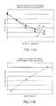
- Figs. 13A and 13B show characteristic graphs for explaining a method for data transmission by a frequency modulation and a load modulation according to the present invention.
- Fig. 14 shows a first part of a flowchart for explaining the operation of an embodiment of the present invention.
- Fig. 15 shows a second part of a flowchart for explaining the operation of an embodiment of the present invention.
- Figs.16A and 16B show schematic views for explaining a coil parameter according to the present invention.
- Figs.17A and 17B show further schematic views for explaining the coil parameter according to the present invention.
- FIG. 1A shows an example of an electronic apparatus configured to employ a method for contactless power transmission according to an embodiment of the present invention.
- a charger 500 (a cradle), which is an electronic apparatus according to an embodiment of the present invention, comprises a power transmission device 10.
- a cell phone 510 which is another electronic apparatus according to an embodiment of the present invention, comprises a power receiving device 40. Further, the cell phone 510 comprises a display 512 such as an LCD or the like, an operation section 514 composed of buttons and the like, a microphone 516 (a voice input section), a speaker 518 (a voice output section), and an antenna 520.
- Power is supplied to the charger 500 through an AC adapter 502, and the power is transmitted from the power transmission device 10 to the power receiving device 40 by contactless power transmission. Accordingly, one or more batteries of the cell phone 510 can be charged through contactless power transmission by the charger 500 and a device in the cell phone 510 can be operated via the buttons of the operation section 514.
- the electronic apparatus according to the present invention is not limited to the cell phone 510.
- the present invention is applicable to various electronic apparatuses such as e.g. a watch, a cordless phone, a shaver, an electric toothbrush, a wrist computer, a handheld terminal, a personal digital assistant, an electric bicycle, or an IC card or other electronic apparatuses comprising a power receiving device.
- contactless power transmission from the power transmission device 10 to the power receiving device 40 is transmitted by electromagnetically coupling a primary coil L1 (e.g. a power transmission coil) used on the power transmission device 10 side and a secondary coil L2 (e.g. a power receiving coil) used on the power receiving device 40 side and thus forming a power transmission transformer. Accordingly, contactless power transmission can be realized.
- a primary coil L1 e.g. a power transmission coil
- a secondary coil L2 e.g. a power receiving coil
- the primary coil L1 and the secondary coil L2 are, for example, embodied by a flat coil having an air-core formed by winding a coil wire in a spiral manner on a plane.
- a coil of the embodiment is not limited to this. Any coil can be employed regardless of its shape, structure, and the like as long as it is possible to transmit power by electromagnetically coupling the primary coil L1 and the secondary coil L2.
- the primary coil L1 can be formed by winding a coil wire in a spiral manner about an X axis with respect to a magnetic substance core.
- the secondary coil L2 provided in the cell phone 510 can be similarly formed.
- the present invention is also applicable to a coil as shown in Fig. 1C .
- a coil formed by winding a coil wire about a Y axis can be used or even combined with a coil formed by winding a coil wire about the X axis.
- Fig. 2 shows a structural example of the power transmission device 10, a power transmission control device 20, the power receiving device 40, and a power receiving control device 50 according to an embodiment of the present invention.
- the electronic apparatus used on a power transmission side such as the charger 500 shown in Fig. 1A comprises the power transmission device 10 as shown in Fig. 2 .
- the electronic apparatus used on a power receiving side such as the cell phone 510 shown in Fig. 1 may comprise the power receiving device 40 and a load 90. According to a structure as shown in Fig.
- a contactless power transmission (non-contact power transmission) system for supplying power to a load 90 can be realized.
- the power transmission device 10 (a power transmission module, a primary module) comprises the primary coil L1, a power transmission section 12, and the power transmission control device 20.
- the structure of the power transmission device 10 and the power transmission control device 20 according to the present invention is not limited to that shown in Fig. 2 , and various modifications, such as omitting a part of the components (e.g. the primary coil), adding another component (e.g. a waveform monitor circuit), or changing connections, can be made.
- the power transmission section 12 (e.g. a power transmission driver) generates an alternating current voltage, and supplies it to the primary coil L1. Specifically, the power transmission section 12 generates an alternating current voltage alternating at a predetermined frequency while transmitting power and an alternating current voltage having a frequency varied (e.g. modulated) corresponding to data while transmitting the data so as to supply the alternating current voltages to the primary coil L1.
- the power transmission section 12 can, for example, comprise a first power transmission driver for driving one end of the primary coil L1, a second power transmission driver for driving the other end of the primary coil L1, and/or one or more capacitors so as to form a resonance circuit together with the primary coil L1.
- Each of the first and the second power transmission drivers provided in the power transmission section 12 is an inverter circuit (e.g. a buffer circuit) composed of, for example, a power MOS transistor, and is controlled by the power transmission control device 20.
- the primary coil L1 i.e. the coil used on the power transmission side
- the secondary coil L2 i.e. the coil used on the power receiving side
- the primary coil L1 and the secondary coil L2 are electromagnetically coupled so as to form a power transmission transformer.
- the cell phone 510 can be placed above the charger 500 so that the primary coil L1 and the secondary coil L2 become electromagnetically coupled as explained above in that magnetic flux of the primary coil L1 passes through the secondary coil L2 for performing contactless power transmission.
- the cell phone 510 can be physically separated from the charger 500 so that the magnetic flux of the primary coil L1 does not pass through the secondary coil L2 (the coils L1 and L2 are then not electromagnetically coupled anymore).
- the power transmission control device 20 is configured to perform various controls of the power transmission device 10, and can be realized for example by an integrated circuit device (an IC).
- the power transmission control device 20 of the embodiment shown in Fig. 2 comprises a controller 22, a storing section 23, and a load condition detection circuit 30.
- further modifications such as omitting a part of the components or adding another component, can be made to form further embodiments of the present invention.
- the controller 22 controls the power transmission device 10 and the power transmission control device 20.
- the controller 22 can be for example realized by an ASIC circuit such as a gate array, a micro computer with a program operates on the micro computer, or the like.
- the controller 22 is configured to control power transmission by using the power transmission section 12, storage of the storing section 23, and the load condition detection circuit 30.
- the controller 22 is configured to control various sequences and performs determination processes required for power transmission, load condition detection (data detection, foreign object detection, removal detection, and the like), a frequency modulation, and the like.
- the storing section 23 (a register) is configured to store various information (data), and can be realized by, for example, a RAM, a D flip-flop, or a nonvolatile memory such as a flush memory and a mask ROM or the like.
- the load condition detection circuit 30 (e.g. a waveform detection circuit) is configured to detect a load condition of the power receiving side (e.g. of a power receiving device or a foreign object). Detection of a load condition can be realized by detecting a variation of the waveform of an induced voltage signal (e.g. a coil terminal signal) of the primary coil L1. For example, in accordance with a variation of a load condition (e.g. a load current) of the power receiving side (i.e. the secondary side), a waveform of the induced voltage signal changes.
- the load condition detection circuit 30 is configured to detect the variation of the waveform, and outputs a detection result (i.e. detection result information or detection result data) to the controller 22.
- the controller 22 based on the detection information (i.e. the detection result) of the load condition in the load condition detection circuit 30, determines a load condition (e.g. a load variation, a degree of the load) of the power receiving side (i.e. the secondary side).
- a load condition e.g. a load variation, a degree of the load
- the power receiving device 40 (e.g. a power receiving module, a secondary module) comprises the secondary coil L2, a power receiving section 42, a power feeding control section 48, and the power receiving control device 50.
- the structure of the power receiving device 40 and the power receiving control device 50 is, however, not limited to that shown in Fig. 2 , and various modifications, such as omitting a part of the components (e.g. the secondary coil), adding another component (e.g. a load modulation section), or changing connections, can be made for forming further embodiments of the present invention.
- the power receiving section 42 is configured to convert an induced alternating current voltage signal of the secondary coil L2 (alternating current voltage) into a direct current voltage.
- This alternating current to direct current conversion can be for example realized by a rectifying circuit included in the power receiving section 42.
- the power feeding control section 48 is configured to control power feeding to the load 90. That is, the power feeding control section 48 controls turning on/off of the power feeding to the load 90. Specifically, a level of the direct current voltage from the power receiving section 42 (e.g. a rectifying circuit) is adjusted so as to generate a power supply voltage. Thereafter, the power supply voltage is supplied to the load 90, e.g. for charging a battery 94 of the load 90.
- the load 90 is not limited to loads comprising a battery 94 but can for example also or even additionally comprise other electronic means which require a direct current voltage as power supply.
- the power receiving control device 50 is configured to perform various controls of the power receiving device 40, and can be for example realized by an integrated circuit device (an IC).
- the power receiving control device 50 operates with a power supply voltage generated from the induced voltage of the secondary coil L2 (i.e. alternating current voltage induced at the secondary coil L2 by magnetic flux from the primary coil L1 of the power transmission side).
- the power receiving control device 50 may include a controller 52 and a storing section 53.
- the controller 52 (on the power receiving side) is configured to control the power receiving device 40 and the power receiving control device 50.
- the controller 52 can for example be realized by an ASIC circuit such as a gate array, a micro computer with a program operates on the micro computer, or the like.
- the controller 52 is configured to control the operation of the power feeding control section 48 and storage of data and information in the storing section 53.
- the controller 52 is configured to control various sequences and performs determination processes required for position detection, frequency detection, a load modulation, full charge detection, or the like.
- the storing section 53 (a register) is configured to store various information (data), and can be realized by, for example, a RAM, a D flip-flop, or a nonvolatile memory such as a flush memory and a mask ROM, or the like.
- the controller 22 of the power transmission side comprises a negotiation processing section 37, a setup processing section 38, and/or a command processing section 39.
- the controller 52 of the power receiving side comprises a negotiation processing section 67, a setup processing section 68, and a command processing section 69.
- the command processing sections 39 and 69 may not be included in the power transmission side and the power receiving side.
- the negotiation process is a confirmation process for confirming whether or not information can be communicated between the power transmission device 10 and the power receiving device 40, a confirmation process for confirming whether or not communicated information is adequate, a confirmation process for confirming whether or not a load condition of the power receiving device side is appropriate, a checking process for checking standard information or coil information between the power transmission device 10 and the power receiving device 40, and/or a checking process for checking system information of the power transmission device 10 with system information of the power receiving device 40, and the like.
- the system information of the power transmission device shows a method for detecting a load condition.
- the communication from the power transmission side to the power receiving side can be for example realized by a frequency modulation of the alternating current voltage signal while communication from the power receiving side to the power transmission side can be for example realized by a load modulation.
- the negotiation processing sections 37 and 67 are configured to perform a negotiation process of contactless power transmission. That is, between the power transmission side and the power receiving side, information on the basic setup of contactless power transmission (e.g. a standard, a coil, a system, a safety feature, and the like) is exchanged during the negotiation process.
- the setup processing sections 38 and 68 based on a result of the negotiation process, are configured to perform a setup process of contactless power transmission. That is, after the basic setup of contactless power transmission is made in the negotiation process, different setup information for each apparatus and application is exchanged between the power transmission side and the power receiving side during the setup process.
- the command processing sections 39 and 69 are configured to perform a command process of contactless power transmission after the performance of the setup process.
- the controller 22 may also start normal power transmission without going through the command process. For example, without the explicit issue of a command, the normal power transmission may be started after the setup process without going through the command process.
- the negotiation process section 37 of the power transmission side is configured to perform a confirmation process for confirming whether or not information can be communicated between the power receiving device 40 and the power transmission device 10, a confirmation process for confirming whether or not communicated information is adequate, and a confirmation process for confirming whether or not a load condition of the power receiving side is appropriate. That is, in the negotiation process, the following are confirmed (checked) by the negotiating process section 37: whether or not information can be appropriately received from the power receiving side; whether or not the information received from the power receiving side is assumed appropriate information; and/or whether the power receiving side is not a foreign object but an appropriate power receiving device (a load). According to further embodiments of the present invention, a load condition of the power receiving side may not be confirmed in the negotiation process.
- the negotiation processing section 37 is configured to perform a checking process for checking standard information, coil information, and system information of the power receiving device 40.
- the system information shows a method for detecting a load condition. That is, the standard information, the coil information and/or the system information received from the power receiving side is checked with that of the power transmission side so as to confirm whether or not the information matches.
- the setup process according to an embodiment of the present invention is a process in which a transmission condition of the power is set based on a result of the above-described negotiation process, a process in which information on a corresponding function between the power transmission device and the power receiving device is exchanged, or the like.
- the setup processing section 38 based on a result of the negotiation process, is configured to set a transmission condition of the contactless power transmission. Specifically, when the power receiving device 40 transmits transmission condition information of contactless power transmission, the setup processing section 38 receives the transmission condition information so as to set transmission condition information of contactless power transmission. That is, when the power receiving device 40 transmits transmission condition information required for the normal power transmission such as a driving voltage of a coil and a driving frequency of the coil, based on the transmission condition information, the setup processing section 38 of the power transmission device 10 sets a transmission condition such as a driving voltage and a driving frequency in accordance with the transmission condition information transmitted from the power receiving device 40. Further, different setup information for each apparatus and application can be exchanged with the power receiving device 40.
- the command process is a process in which a command that is confirmed to be available by at least one of the negotiation processing section and the setup processing section during at least one of the negotiation process and the setup process is issued and/or executed.
- the command includes a command for starting normal power transmission, a command for detecting a full charge of a battery included in the load, a command for checking whether a battery included in the load is in a fully charged condition, a command for confirming whether or not a recharge of the battery is required, and/or a command for detecting a charging condition of a battery included in the load or the like.
- the command processing section 39 processes various commands such as the command for starting normal power transmission, the command for detecting a full charge of the battery 94 (i.e. a command for notifying a full charge of the battery), and the command for confirming a recharge of the battery 94. That is, the command processing section 39 is configured to issue and execute these commands. As the command, at least the command for starting normal power transmission is prepared. Other commands can be treated as optional commands according to the afore-mentioned commands.
- the controller 22 is configured to stop (or interrupt) the normal power transmission when this is requested by the power receiving device 40, e.g. when a corresponding command is issued by the power receiving device 40, in particular by the command processing section 53.
- the normal power transmission is stopped.
- a full charge of the battery 94 can be detected, and the command for detecting a full charge is transmitted.
- the controller 22 receives the command for detecting a full charge, the normal power transmission started with the command for starting normal power transmission is stopped (or interrupted).
- the controller 22 moves into a standby phase after detecting the full charge. That is, after detecting the full charge of the battery 94, the controller 22 is in a mode of standby until a recharge of the battery 94 is required, e.g. until it is detected that a recharge of the battery 94 is required. At this time, since the normal power transmission from the power transmission side is stopped, a power supply voltage is not supplied to the power receiving device 40. Thus, the state of the power receiving device 40 becomes a reset state.
- the controller 22 is configured to confirm whether a recharge of the battery is required in the standby phase of the controller 22 after detecting the full charge (i.e. after the normal power transmission has been stopped as described above). That is, for example, temporary power transmission is repeatedly (e.g. periodically) carried out for a predetermined period so as to awake the power receiving device 40 from the reset state. Then, the command for confirming a recharge is issued so as to confirm whether or not a recharge of the battery 94 is required. At this time, in the standby phase after detecting the full charge, a flag for confirming a recharge is maintained in a set state without being cleared.
- a standby phase after detecting the full charge indicates a phase in which normal power transmission for supplying power to a load e.g. for charging a battery is stopped (or interrupted) e.g. after it is detected that the battery is fully charged, wherein the electronic apparatus on the power receiving side such as the cell phone 510 is not removed or separated from the electronic apparatus on the power transmission side such as the charged 500 after the normal power transmission has been stopped (or interrupted).
- the electronic apparatus on the power receiving side such as the cell phone 510 is separated or removed from the electronic apparatus on the power receiving side such as the charger 510, e.g. in that it is picked up by a user.
- the controller 22 moves from the standby phase after detecting the full charge into a standby phase after detecting the removal. In this case, the flag for confirming a recharge is cleared.
- the controller 22 moves into a negotiation processing phase (e.g. for performing a negotiation process as described above). Then, after going through the setup process and the like, for example, the normal power transmission is started (initiated).
- the negotiation process section 67 on the power transmission side is configured to perform a confirmation process for confirming whether or not information can be communicated with the power transmission device 10 (i.e. between the power transmission device 10 and the power receiving device 40), and a confirmation process for confirming whether or not communicated information is adequate.
- the negotiation processing section 67 is configured to perform a checking process for checking standard information, coil information, and/or system information that shows a method for detecting a load condition. That is, the negotiation process section 67 is configured to transmit standard information, coil information, and/or system information to the power transmission side, and receives that of the power receiving side from the power transmission side so as to confirm whether or not the information of the power transmission side and the power receiving side matches.
- the setup processing section 68 based on a result of the negotiation process, is configured to transmit transmission condition information of contactless power transmission to the power transmission device 10. That is, the transmission condition information such as the driving voltage and the driving frequency of the coil required for the normal power transmission is transmitted. In addition, different setup information for each apparatus and application is exchanged with the power transmission device 10.
- the command processing section 69 performs various command processes such as the command for starting normal power transmission, the command for detecting a full charge of the battery 94, and the command for confirming a recharge of the battery 94. That is, the command processing section 69 is configured to issue and execute these commands.
- the controller 52 may start power supply to the load 90 without going through the command process. For example, without the explicit issue of a command, the power supply to the load 90 may be started after the setup process.
- Fig. 3 schematically shows a process sequence of contactless power transmission realized by an embodiment of the present invention.
- a flag represents (i.e. indicates) a condition of the power transmission device and the power receiving device (a power transmission condition, a full charge condition, a recharge confirmation condition, or the like), and maintained by at least one of the storing sections 23 and 53 (registers) of the devices.
- the power transmission side maintains the last state of the power receiving side (the secondary side) when the power transmission is stopped. For example, if a full charge of the battery is detected, the power transmission side and the power receiving side move into the standby phase after detecting the full charge as described above. In this case, since the battery is recharged after detecting a decrease in a battery voltage, the power transmission side stores a number of stopping the power transmission after detecting the full charge. Specifically, a flag for confirming a recharge is maintained in the set state without being cleared so as to periodically confirm whether or not a recharge is required.
- the power transmission from the power transmission side to the power receiving side is stopped.
- a power supply voltage is not supplied to the power receiving side, so that the power receiving side is in a stop state.
- the power transmission side is in an operating state. Accordingly, since an operation is stopped in the power receiving side in the standby phase, low power consumption is achieved.
- the flags in various states are maintained without being cleared in the power transmission side, so that the power transmission side can perform various processes with the flags after the standby phase.
- the power transmission side and the power receiving side move into the negotiation phase after the standby phase.
- a negotiation process is performed.
- a match of standard information, coil information, and/or system information is confirmed and safety information is exchanged.
- the power transmission side and the power receiving side exchange standard information, coil information and/or system information so as to confirm whether or not the information matches with each other.
- safety threshold information for detecting a foreign object e.g. a foreign object between the primary coil L1 and the secondary coil L2 and the like are transmitted from the power receiving side to the power transmission side so as to exchange safety information.
- the following are confirmed: whether or not information can be communicated between the power transmission side and the power receiving side; whether or not communicated information is adequate; whether or not a load condition of the power receiving side is appropriate (e.g. detection that there is no foreign object, i.e. that the electronic apparatus on the power receiving side is an appropriate or adequate electronic apparatus for receiving power); and the like.
- the power transmission side and the power receiving side move into the reset state, and the various flags are cleared: a mismatch of standard information, coil information, and/or system information is determined; a foreign object is detected; a removal of the apparatus is detected; or a timeout error is caused.
- a communication error is caused, the power transmission side and the power receiving side move into the standby phase for example, and the flags are not cleared.
- the power transmission side and the power receiving side move into the setup phase after the negotiation phase.
- a setup process is performed in which setup information such as information on a corresponding function and setup information for each application is transferred.
- setup information such as information on a corresponding function and setup information for each application is transferred.
- a transmission condition of contactless power transmission is set.
- the power receiving side transmits the transmission condition information such as the driving voltage and the driving frequency of the coil to the power transmission side
- the power transmission side sets a transmission condition such as the driving voltage and the driving frequency of the coil for the normal power transmission based on the received transmission condition information.
- information on a corresponding function and different setup information for each application above is also exchanged in the setup process.
- the information include kinds of command that can be issued and executed by the power transmission side or the power receiving side in a command phase, and an additional corresponding function such as a periodic authentication function. Accordingly, different setup information can be exchanged in accordance with an application such as kinds (e.g. a cell phone, audio equipment, and the like) and models of the electric apparatus.
- the power transmission side and the power receiving side move into the reset state if a removal of the apparatus is detected or a timeout error is caused.
- the power transmission side and the power receiving side move into the standby phase if a communication error and the like are caused.
- a command process is performed based on the information obtained in the setup process. That is, a corresponding command (a command that is confirmed to be available in the setup process) is issued and executed.
- the command executed in the command process includes, for example, the command for starting normal power transmission (e.g. for charging a battery on the power receiving side), the command for detecting (notifying) a full charge, the command for confirming a recharge, a command for interrupting the power receiving side, a command for requesting a power transmission stop, or the like.
- the power transmission side transmits (issues) the command for starting normal power transmission (e.g. for charging a battery on the power receiving side) to the power receiving side. Then, the power receiving side receives the command and transmits a response command to the power transmission side so as to start the normal power transmission. If a full charge is detected in the power receiving side after the normal power transmission is started, the power receiving side transmits the command for detecting a full charge to the power transmission side.
- the power transmission side and the power receiving side move into the standby phase after detecting the full charge.
- the power transmission side transmits the command for confirming a recharge to the power receiving side.
- the power receiving side is for example configured to check a battery voltage so as to determine whether or not a recharge of the battery is required based on a determined battery voltage. If it is determined that a recharge is required, the flag for confirming a recharge is reset. Then, the power transmission side issues the command for starting the normal power transmission so as to restart the normal power transmission. On the other hand, if a recharge is not required, the flag for confirming a recharge is maintained in the set state. Then, the power transmission side and the power receiving side return to the standby phase after detecting the full charge.
- the power transmission side and the power receiving side move into the reset state.
- a placement is detected every k1 seconds, e.g. it is determined whether an electronic apparatus on the power receiving side such as a cell phone 510 is placed (again) above the electronic apparatus on the power transmission side such as a charger 500 periodically every k1 seconds, for example.
- the negotiation process and the setup process are performed as described above. If the negotiation process and the setup process are normally ended as shown with reference to reference sign F3, the command for starting normal power transmission is issued in the command process.
- the normal power transmission is started so as to start charging the electronic apparatus.
- an LED of the electronic apparatus can be switched on for indicating the process of normal power transmission. If a full charge is detected as shown with reference to reference sign F4, the LED of the electronic apparatus can be turned off again. Then, the process sequence moves into the standby phase after detecting the full charge as shown with reference to reference sign F5.
- a removal is periodically detected every k3 seconds and a recharge is simultaneously confirmed every k3 x j seconds. Then, in the standby phase after detecting the full charge, if a removal of the electronic apparatus is detected as shown with reference to reference sign F6, the process sequence moves into the standby phase after detecting the removal. On the other hand, in the standby phase after detecting the full charge, if a recharge is determined to be required by confirmation as shown with reference to reference sign F7, the negotiation process and the setup process are performed. Then, the normal power transmission is restarted so as to start recharging the battery. If a removal of the electric apparatus is detected during the normal power transmission as shown in F8, the process sequence moves into the standby phase after detecting the removal.
- Fig. 5A shows a format example of a negotiation frame as can be transferred in the negotiation process.
- the negotiation frame comprises a beginning field (start field), an information field, and a final field (end field).
- the information field comprises a matching code and a hardware information code.
- Fig. 5B shows a format example of the matching code.
- the matching code comprises a command ID, a standard code, an extension code, and a coil code.
- the command ID represents the matching code.
- the standard code represents a version of the standard, e.g. representing the above-mentioned standard information.
- the extension code represents an ID code system. For example, a code length is controlled by an extension code management form or the like.
- the coil code represents coil information, and comprises a segment code (classification code) and a coil ID (coil identification information), for example.
- the segment code is used for specifying an administrator of the coil ID.
- the coil ID is given to the primary coil (a primary coil unit) by the administrator. That is, not only to the power transmission side, but an ID of the primary coil of the power transmission side as a coil ID is also given to the power receiving side.
- the definition of a coil ID changes depending on the extension code. For example, if the extension code is in a first setting, the coil code is set so as to divide the segment code and the coil ID. On the other hand, if the extension code is set in a second setting, the coil code is set without dividing the segment code and the coil ID.
- Fig. 5C shows a format example of the hardware information code.
- the hardware information code includes a system code and a threshold of a foreign object.
- the system code represents system information, and specifically is information representing a method for detecting a load condition of the power transmission side and the power receiving side. Examples of the method for detecting a load condition include a pulse width detection method (a phase detection method), a current detection method, a peak voltage detection method, or a combination of these methods.
- the system code shows a method employed by the power transmission side and the power receiving side.
- the threshold of a foreign object is safety threshold information (representing the above safety information).
- the threshold of a foreign object for example, is stored in the power receiving side, and is transmitted from the power receiving side to the power transmission side before the normal power transmission is started.
- the power transmission side based on the threshold of a foreign object, performs a first foreign object detection that is foreign object detection before starting the normal power transmission. For example, if a load condition of the power receiving side is detected by the pulse width detection method, a threshold of a pulse width count value is transmitted from the power receiving side to the power transmission side as a threshold of a foreign object. Based on the threshold of a pulse width count value, the power transmission side performs the first foreign object detection by the pulse width detection method.
- the suitability of standard, coil, and/or system is determined based on the standard information, coil information, and/or system information and minimum safety information is exchanged in the negotiation process. Further, in the negotiation process, the possibility of communication and the adequacy of the communication information are determined as well as the propriety of a load condition of the power receiving side is determined.
- a setup and the like of a transmission condition required for the normal power transmission are made.
- the driving voltage and the driving frequency of the coil are set.
- information on an additional corresponding function and setup information required for each application above is exchanged in the setup process.
- the process sequence moves into the command phase for the command process. That is, a command confirmed to be available in the negotiation process is issued and executed in the command process.
- the minimum information required for the suitability of the system and the secured safety is exchanged in the negotiation process, and the different setup information for each application is exchanged in the setup process.
- the negotiation process only the minimum information is transferred, thereby an amount of transferred information can be reduced.
- the negotiation phase is ended in a short time, allowing the process to be more efficient.
- Each apparatus of the power transmission side and the power receiving side can perform minimum contactless power transmission by the negotiation process, and enhancement of function for each apparatus can be realized by exchanging the setup information.
- Each apparatus makes the minimum setting required for a contactless power transmission system in the negotiation process, and the system can be optimized in the setup process. As a result, an efficient and flexible system can be realized.
- the power transmission side receives threshold information (safety threshold information, safety information) and system information from the power receiving side.
- threshold information safety threshold information, safety information
- system information system information from the power receiving side.
- the power receiving side transmits an appropriate combination of coil information and threshold information to the power transmission side, so that appropriate and safe contactless power transmission can be realized.
- a method of comparison example such that a device ID of the power receiving device is transmitted to the power transmission device so that the power transmission device authenticates ID by using the device ID.
- a situation is not assumed or considered according to which a plurality of secondary coils, e.g. of different electronic apparatuses (on power receiving side), correspond to a single primary coil of an electronic apparatus on the power transmission side. Accordingly, if various types of secondary coils are marketed, it is hard to deal with it. That is, if the plurality of the secondary coils correspond to a single primary coil, the electronic apparatus on the power transmission side has to store a plurality of device IDs. Therefore, management becomes complex.
- a method is employed such that the storing section 23 of the power transmission side stores coil information of the power transmission side and the storing section 53 of the power receiving side stores coil information of the power receiving side so as to transmit and receive these coil information. If such a method according to the present invention is employed, since management is not that complicated, a plurality of the secondary coils can correspond to a single coil even if various types of secondary coil are marketed.
- a primary coil X a primary coil of a first type in a broad sense
- plural secondary coils XA, XB, and XC secondary coils of a first to an n types in a broad sense
- a combination of the primary coil X with each of the secondary coils XA, XB, or XC is an appropriate combination.
- a primary coil on the power transmission side can be efficiently and appropriately combined with different secondary coils of different type on the power receiving side according to the present invention so as to allow respective appropriate contactless power transmission for all combinations. Accordingly, for the different combinations, it is assured that appropriate contactless power transmission can be realized.
- secondary coils YA, YB, and YC can correspond to a primary coil Y.
- the power transmission device 10 including the primary coil X stores IDX, i.e. the coil ID of the primary coil X, as coil information of the power transmission side.
- the power receiving device 40 including the secondary coil XA also stores IDX, i.e. the corresponding coil ID of the primary coil X, as coil information of the power receiving side.
- the power transmission device 10 determines whether or not the stored coil information of the power transmission side and IDX of the coil information of the power receiving side received from the power receiving device 40 match, i.e. whether the coil information of the power transmission side is also IDX, i.e. the coil ID of the primary coil X, or not. If it is determined that the coil information matches, the normal power transmission is started.
- IDX i.e. the coil ID of the primary coil X
- the power receiving device 40 including the secondary coil YA transmits IDY, coil information of the power receiving side, to the power transmission device 10 including the primary coil X.
- IDX identification information of the primary coil of the first type
- a coil ID of the primary coil X as coil information of the power receiving side when the secondary coil is any of one of the coils XA, XB, and XC (the first to the n types of coils).
- an ID of the primary coil to which the secondary coil itself belongs is given to each secondary coil. Accordingly, on the power receiving side having the secondary coil, only the ID of its primary coil needs to be stored, and an ID of the secondary coil does not need to be stored on the power receiving side. Also, on the power transmission side, only the ID of the primary coil, e.g. IDX, needs to be stored, and plural IDs of corresponding secondary coils, e.g. IDs of coils XA, XB, XC, do not need to be stored on the power transmission side. Therefore, management and the like can be simplified.
- the power transmission side may store a plurality of coil information of the power transmission side. For example, in Fig. 6 , if the power transmission side can correspond to at least one of the primary coil X and the primary coil Y, IDX, coil information of the primary coil X, and IDY, coil information of the primary coil Y, are stored as coil information of the power transmission side. Then, if IDX, coil information of the coil XA, is transmitted from the power receiving device 40, the power transmission device 10 transmits IDX to the power receiving device 40. IDX is the matched coil information to the coil information of the power receiving side out of the plurality of the coil information of the power transmission side, IDX and IDY.
- IDY coil information of the coil YA
- the power transmission device 10 transmits IDY to the power receiving device 40.
- IDY is the matched coil information to the coil information of the power receiving side out of IDX and IDY. Accordingly, variations of matched coils between the primary side and the secondary side can be increased, whereby more flexible system can be achieved.
- the power transmission device 10 starts temporary power transmission (power transmission for detecting a position) before starting the normal power transmission. With this temporary power transmission, a power supply voltage is supplied to the power receiving device 40, so that the power receiving device 40 is turned on.
- the power receiving device 40 determines whether or not a positional relation between the primary coil L1 and the secondary coil L2 is appropriate. Specifically, the power receiving device 40 determines whether or not the positional relation between the primary coil L1 and the secondary coil L2 is a relation shown in Fig. 1B , for example.
- the power receiving device 40 (the negotiation processing section 67) generates a negotiation frame so as to transmit the negotiation frame to the power transmission device 10.
- the negotiation frame comprises, for example, standard information, coil information, system information, and/or threshold information (safety threshold information, safety information).
- the power transmission device 10 (the negotiation processing section 37) receives the negotiation frame from the power receiving device 40
- the standard information, coil information, and/or system information of the power receiving side included in the received negotiation frame is checked with that of the power transmission side stored in the storing section 23. That is, a confirmation process is performed for confirming whether or not information can be communicated and whether or not communicated information is adequate.
- the threshold information received from the power receiving device 40 is set as threshold information for detecting a load condition of the power receiving side.
- the power transmission device 10 based on the threshold information received from the power receiving device 40, detects insertion of a foreign object between the primary coil L1 and the secondary coil L2. That is, the power transmission device 10 confirms whether or not a load condition of the power receiving side is appropriate. Then, as shown in Fig. 8A , if it is determined that the standard information, coil information, and/or system information matches and no foreign object is detected, the power transmission device 10 makes a negotiation frame including the standard information, coil information, and/or system information of the power transmission side so as to transmit it to the power receiving device 40.
- the power receiving device 40 checks the standard information, coil information, and/or system information of the power receiving side with that included in the received negotiation frame. Then, as shown in Fig. 8B , the power receiving device 40 (the setup processing section 68) generates a setup frame so as to transmit it to the power transmission device 10.
- the setup frame for example, comprises the transmission condition information such as the driving voltage and the driving frequency of the coil and corresponding function information that shows a function (a command and the like) corresponding to the power receiving side.
- the power transmission device 10 (the setup processing section 38) receives the setup frame, based on the transmission condition information received from the power receiving side, it sets a transmission condition of the normal power transmission. Further, based on the received corresponding function information of the power receiving side, it is determined that whether or not the corresponding function is matched between the power transmission side and the power receiving side. Then, as shown in Fig. 8C , the power transmission device 10 generates a setup frame comprising corresponding function information of the power transmission side so as to transmit to the power receiving device 40. Then, based on the received corresponding function information of the power transmission side, on the power receiving side it is determined whether or not the corresponding function is matched between the power transmission side and the power receiving side.
- the command process is performed. That is, the power transmission device 10 (the command processing section 39) and the power receiving device 40 (the command processing section 69) issue or execute a corresponding command.
- the power receiving device 40 transmits a start frame to the power transmission device 10. Then, as shown in Fig. 9C , the power transmission device 10 issues the command for starting normal power transmission (e.g. a command for starting a charging operation) so as to transmit the command to the power receiving device 40.
- the power receiving device 40 transmits a response command as a response to the command for starting normal power transmission so as to transmit the response command to the power transmission device 10. Accordingly, the power transmission device 10 and the power receiving device 40 perform the command process for the normal power transmission.
- the power transmission device 10 starts the normal power transmission to the power receiving device 40.
- the driving voltage and the driving frequency of the coil the one set in the setup frame shown in Figs. 8B and 8C is used.
- the power receiving device 40 issues the command for detecting a full charge to notify the detection of a full charge to the power transmission device 10. Specifically, the power receiving device 40 generates a save frame including the command for detecting a full charge so as to transmit the command for detecting a full charge to the power transmission device 10. Accordingly, the power transmission device 10 stops the power transmission to the power receiving device 40, and moves into the standby phase after detecting the full charge. In the standby phase, it is confirmed for each predetermined period whether or not a recharge of the battery 94 is required, e.g. periodically.
- the power transmission device 10 sets the flag for confirming a recharge to one for confirming whether or not a recharge is required. That is, in the standby phase after detecting the full charge, the flag for confirming a recharge is maintained in the set state without being cleared. Then the power transmission device 10 starts temporary power transmission to the power receiving device 40 so as to perform the negotiation process, the setup process, and the command process.
- the power transmission device 10 issues the command for confirming a recharge so as to transmit it to the power receiving device 40. Accordingly, the power receiving device 40 confirms a battery voltage (a charging voltage) of the battery 94. If it is determined that a recharge of the battery 94 is required, the power receiving device 40 transmits the command for starting a charge. Then, the power transmission device 10 resets the flag for confirming a recharge to zero, and starts the normal power transmission after the negotiation process, the setup process, and the command process.
- a battery voltage a charging voltage
- the power transmission device 10 moves into the negotiation processing phase. After going through the setup process and the command process, for example, the normal power transmission is started. Accordingly, a charge of the battery 94 of the placed electronic apparatus is started.
- a sequence process is performed in which the negotiation process, the setup process, and the command process are subsequently performed. Accordingly, the minimum information required for the suitability of the system and the secured safety is exchanged in the negotiation process, and the different setup information for each application and apparatus is exchanged in the setup process.
- a contactless power transmission system with high versatility and capable of improving efficiency can be provided. Since the minimum setting is made in the negotiation process and the system can be optimized in the setup process, a flexible and efficient system can be realized.
- a specific structural example of an embodiment according to the present invention is shown in Fig. 12 .
- elements which are similar to the elements described in Fig. 2 are indicated by the same numerals and the description thereof is omitted.
- the following description of the specific structural example and the corresponding specific features of the specific structural example are, however, not meant to limit the embodiment of the present invention as shown in Fig. 2 .
- a waveform monitor circuit 14 (e.g. a rectifying circuit), based on a coil terminal signal CGS, generates an induced voltage signal PHIN for a waveform monitor.
- the coil terminal signal CGS that is an induced voltage signal for the primary coil L1 may exceed a maximum rating voltage of an IC of the power transmission control device 20 or become a negative voltage.
- the waveform monitor circuit 14 receives the coil terminal signal CGS so as to generate the induced voltage signal PHIN for a waveform monitor and output to a terminal for a waveform monitor of the power transmission control device 20.
- the induced voltage signal PHIN is capable of being detected as a waveform by the load condition detection circuit 30 of the power transmission control device 20.
- a display 16 displays various conditions of the contactless power transmission system (e.g. conditions of power transmitting, ID authenticating, and the like) with colors, images, and the like.
- An oscillation circuit 24 generates a clock for the primary side.
- a driving clock generating circuit 25 generates a driving clock defining a driving frequency.
- the load condition detection circuit 30 shapes a waveform of the induced voltage signal PHIN so as to generate a waveform shaping signal. For example, if the signal PHIN is beyond a predetermined threshold voltage, the load condition detection circuit 30 generates a waveform shaping signal (e.g. a pulse signal) of a square wave (e.g. a rectangular wave) that becomes active (e.g., an H level).
- a waveform shaping signal e.g. a pulse signal
- the load condition detection circuit 30 based on the waveform shaping signal and the driving clock, detects pulse width information (e.g. a pulse width period) of the waveform shaping signal. Specifically, the load condition detection circuit 30 receives the waveform shaping signal and the driving clock from the driving clock generating circuit 25 so as to detect pulse width information of the waveform shaping signal. Accordingly, the pulse width information of the induced voltage signal PHIN is detected.
- the detection method is not limited to the pulse width detection method (e.g. a phase detection method), and various further methods, such as a current detection method, a peak voltage detection method, or even combinations thereof can be employed.
- the controller 22 (the power transmission control device), based on a detection result in the load condition detection circuit 30, determines a load condition (e.g. a load variation, a degree of the load) of the power receiving side (the secondary side). For example, the controller 22, based on the pulse width information detected in the load condition detection circuit 30 (e.g. a pulse width detection circuit), determines a load condition of the power receiving side. Then, the controller 22 detects, for example, data (e.g. a load), a foreign object (e.g. metal), a removal (e.g. set and removal), and the like. That is, a pulse width period that is the pulse width information of the induced voltage signal changes in accordance with a load condition of the power receiving side. The controller 22 can detect a load fluctuation of the power receiving side based on the pulse width period (e.g. a count value obtained by measuring the pulse width period).
- a load condition e.g. a load variation, a degree of the load
- the controller 22 determines
- the power receiving section 42 converts an induced alternating current voltage signal of the secondary coil L2 into a direct current voltage.
- the alternating current to direct current conversion is performed by a rectifying circuit 43 included in the power receiving section 42.
- a load modulation section 46 performs a load modulation process. Specifically, when desired data is transmitted from the power receiving device 40 to the power transmission device 10, a load of the load modulation section 46 (on the secondary side) is variably changed so as to change (modulate) a signal waveform of the induced voltage of the primary coil L1. Accordingly, the load modulation section 46 includes a resistance RB3 provided in series between nodes NB3 and NB4, and a transistor TB3 (e.g. an N-type CMOS transistor). The transistor TB3 is on/off controlled by a signal P3Q from the controller 52 of the power receiving control device 50. When the transistor TB3 is on/off controlled so as to perform a load modulation, a transistor TB2 of the power feeding control section 48 is turned off. Accordingly, the load 90 is in a state of not being electrically coupled to the power receiving device 40.
- the power feeding control section 48 controls power feeding to the load 90.
- a regulator 49 adjusts a voltage level of a direct current voltage VDC obtained by the conversion in the rectifying circuit 43 so as to generate a power supply voltage VD5 (e.g., 5V).
- the power receiving control device 50 operates with a supply of the power supply voltage VD5, for example.
- the transistor TB2 (e.g. a P-type CMOS transistor, a power feeding transistor) is controlled by a signal P1Q from the controller 52 of the power receiving control device 50. Specifically, the transistor TB2 is turned off during the negotiation process and the setup process while turned on after the normal power transmission is started.
- a position detection circuit 56 determines whether or not a positional relation between the primary coil L1 and the secondary coil L2 is appropriate.
- An oscillation circuit 58 generates a clock for the primary side.
- a frequency detection circuit 60 detects a frequency (f1 and f2) of a signal CCMPI.
- a full charge detection circuit 62 detects whether or not the battery 94 (a secondary battery) of the load 90 is in a full charge state (a charge state).
- the load 90 may include a charge control device 92 performing a charge control and the like of the battery 94.
- the charge control device 92 e.g. a charge control IC
- the battery 94 itself may have a function of the charge control device 92.
- data communication from the power transmission side to the power receiving side can be realized by a frequency modulation while data communication from the power receiving side to the power transmission side can be realized by a load modulation (amplitude modulation).
- the power transmission section 12 when data 1 is transmitted to the power receiving side, the power transmission section 12 generates an alternating current voltage of the frequency f1. On the other hand, when data 0 is transmitted, the power transmission section 12 generates an alternating current voltage of the frequency f2. Then, the frequency detection circuit 60 of the power receiving side detects a change in the frequency so as to determine data 1 or 0. Accordingly, data communication by a frequency modulation from the power transmission side to the power receiving side can be realized.
- a load of the power receiving side is variably changed in accordance with transmitted data. Accordingly, as shown in Fig. 13B , a signal waveform of the induced voltage of the primary coil L1 is changed. For example, when data 1 is transmitted to the power transmission side, the power receiving side is in a high load condition. On the other hand, when data 0 is transmitted, the power receiving side is in a low load condition. Then, the load condition detection circuit 30 of the power transmission side detects a change in the load condition of the power receiving side so as to determine data 1 or 0. Accordingly, data communication by a load modulation from the power receiving side to the power transmission side can be realized.
- data communication from the power transmission side to the power receiving side can be realized by a frequency modulation while data communication from the power receiving side to the power transmission side can be realized by a load modulation.
- another modulation method or other method may be employed.
- step S2 By turning on a power, on the power transmission side, for example, after a wait of k1 seconds (step S1), temporary power transmission is performed (step S2) before starting the normal power transmission.
- the temporary power transmission is temporary electric power transmission for placement detection, position detection, or the like. That is, for example, the temporary power transmission is for detecting whether or not the electronic apparatus on the power receiving side such as a cell phone is placed above the electronic apparatus on the power transmission side such as a charger as shown with reference to reference sign F2 in Fig. 4 .
- the temporary power transmission is, for example, for detecting whether or not the electronic apparatus on the power receiving side is placed above the electronic apparatus on the power transmission side in an appropriate position, which is suitable for appropriate normal power transmission.
- a driving frequency (e.g. a frequency of a driving clock from the driving clock generating circuit) of the temporary power transmission is set to the f1, for example.
- the temporary power transmission from the power transmission side allows the power receiving side to be turned on (step S22) and a reset of the power receiving control device 50 to be released. Then, the power receiving control device 50 sets the signal P1Q shown in Fig. 12 to the H level. Accordingly, the transistor TB2 of the power feeding control section 48 is turned off (step S23), so that the electrical connection between the power receiving side and the load 90 is interrupted.
- the power receiving side determines whether or not a positional relation (a position level) between the primary coil L1 and the secondary coil L2 is appropriate (step S24). If the positional relation is not appropriate, the power receiving side waits, for example, for a period of k2 seconds.
- the electronic apparatus on the power receiving side generates a negotiation frame so as to transmit to the power transmission side (step S25). Specifically, by the load modulation as described above with reference to Fig. 13B , the negotiation frame is transmitted.
- the negotiation frame includes, for example, standard information stored in the storing section 53 of the receiving side, a matching code such as coil information, and/or hardware information such as system information (a method for detecting a load condition) and threshold information (threshold of detecting a load condition).
- step S4 When electronic apparatus on the power transmission side receives the negotiation frame (step S4), electronic apparatus on the power transmission side verifies the negotiation frame (step S5). Specifically, on the power transmission side, it is confirmed whether or not the standard information, coil information, and/or system information stored in the storing section 23 of the power transmission side and that received from the power receiving side match. Then, if the negotiation frame is determined to be appropriate, foreign object detection is performed (step S6).
- the electronic apparatus on the power transmission side sets a driving frequency to a frequency for detecting a foreign object f3. Then, based on the threshold information (safety threshold information, safety information) received from the power receiving side, a first foreign object detection before starting the normal power transmission is performed so as to determine whether or not a load condition of the power receiving side is appropriate. For example, an enable signal for detecting a foreign object is activated so as to instruct the load condition detection circuit 30 to start detecting a foreign object.
- the detection of foreign object can be realized by comparing, for example, load condition detection information (e.g. pulse width information) from the load condition detection circuit 30 with a threshold of detecting a load condition (META) received from the power receiving side. After the period of detecting a foreign object ends, the electronic apparatus on the power transmission side returns the frequency to the frequency for normal power transmission f1.
- load condition detection information e.g. pulse width information
- MEA threshold of detecting a load condition
- the power transmission side stops the power transmission so as to return to the step S1.
- a negotiation frame is generated so as to be transmitted to the power receiving side (step S7).
- the negotiation frame comprises, for example, standard information, coil information, and/or system information stored in the storing section 23 of the power transmission side.
- the negotiation frame is verified on the power receiving side (step S27). Specifically, it is confirmed on the power receiving side whether or not the standard information, coil information, and/or system information stored in the storing section 53 on the power receiving side and that received from the power transmission side match. Then, if the negotiation frame is determined to be appropriate, on the power receiving side a setup frame is generated so as to be transmitted to the power transmission side (step S28).
- the setup frame comprises parameter data such as transmission condition information and corresponding function information.
- the transmission condition information comprises such as the driving voltage and the driving frequency of the primary coil.
- the corresponding function information represents an additional function for each application and the like. If the setup frame is not appropriate, the power receiving side returns to the step S21.
- step S8 When the setup frame is received on the power transmission side (step S8), the setup frame is verified on the power transmission side (step S9). If the setup frame from the power receiving side is appropriate, a negotiation frame of the power transmission side is generated on the power transmission side so as to transmit it to the power receiving side (step S10). On the other hand, if the setup frame is not appropriate, the power transmission is stopped on the power transmission side so as to return to the step S1.
- the setup frame (step S30) is verified on the power receiving side. If the setup frame is appropriate, a start frame is generated on the power receiving side so as to transmit it to the power transmission side (step S31). On the other hand, if the setup frame is not appropriate, the power receiving side returns to the step S21.
- the power transmission side and the power receiving side move into a command branch (steps S41 and S61). That is, a command determination is performed so as to split into a command process corresponding to each flag.
- the command for starting normal power transmission (a charge) is transmitted from the power transmission side to the power receiving side (step S42).
- the command for starting normal power transmission is received on the power receiving side (step S62)
- step S43 When the response command is received on the power transmission side (step S43), various parameters are switched to a parameter for normal power transmission (step S44). Specifically, a parameter for a transmission condition and the like are switched to a parameter set in the setup process. Then, periodic authentication is turned on (step S45), and the normal power transmission is started (step S46).
- the transistor TB2 of the power feeding control section 48 is turned on so as to start power supply to the load 90.
- the periodic authentication is turned on so as to perform a periodic load modulation (step S66). Specifically, the transistor TB3 of the load modulation section 46 is turned on/off in a predetermined pattern in a periodic authentication period.
- step S47 After the normal power transmission is started, in the periodic authentication period performed by the periodic load modulation, a takeover state caused by a metal foreign object and the like having a large area is detected on the power transmission side (step S47). Further, removal detection and foreign object detection are performed (steps S48 and S40). If any takeover in the periodic authentication, a removal, or a foreign object is detected, the power transmission is stopped so as to return to the step S1.
- step S67 After the normal power transmission is started, it is detected on the power receiving side whether or not the battery 94 is fully charged (step S67). If a fully charged condition is detected, the transistor TB2 is turned off (step S68), and the power supply to the load 90 is stopped. Further, the periodic authentication is turned off (step S69). Then, the command for detecting a full Il charge (a save frame) that notifies detection of a fully charged condition is transmitted to the power transmission side (step S70), and after a wait period of k4 seconds (step S71), the process of the step 70 is repeated.
- step S53 When the command for detecting a full charge (a save frame) is received on the power transmission side, the periodic authentication is turned off, and the power transmission is stopped (steps S51 and S52). Then, the power transmission side moves into the standby phase after detecting the full charge (step S53).
- step S54 In the standby phase after detecting the full charge, for example, a removal is detected every k3 seconds (step S54). Then, if a removal is detected, the flag for confirming a recharge is reset to zero (step S57), and the power transmission is stopped so as to return to the step S1.
- step S55 and S56 the flag for confirming a recharge is set to one.
- the power transmission is stopped so as to return to the step S1.
- the negotiation process and the setup process are performed. Since the flag for confirming a recharge is one at the command branch of the step S41, the power transmission side moves into the command process of confirming a recharge.
- a coil parameter comprises an inner diameter, an outer diameter, a coil area, and the like.
- the coil parameter represents characteristics of a coil.
- a single coil having a fixed coil parameter is prepared as the primary coil and various coils having different coil parameters are prepared as the secondary coil so as to perform a measurement.
- Fig. 16B shows a measured value showing a relation of a count value of pulse width detection and an output current (e.g. a load) when the inductance is adjusted so as to have the same output current.
- G1 is a measured value of the secondary coil having a smaller coil area while G2 is a measured value of that having a larger coil area.
- Fig. 17A shows a measured value showing a relation of a count value of pulse width detection and an output current when the inductance is adjusted by the secondary coils having the same outer diameter.
- G3 is a measured value of the secondary coil having the smallest coil area
- G5 is a measured value of that having the largest coil area
- G4 is a measured value of that having a medium coil area.
- a fluctuation range of the count value of pulse width detection to a load fluctuation becomes smaller when the coil area of the secondary coil is small. Accordingly, when a coil area of the secondary coil is changed in accordance with a size and the like of the electronic apparatus, a threshold and the like are set by considering variability characteristics of the count values of Figs. 16B and 17A .
- Fig. 17B shows a relation of an inductance and an output voltage with the secondary coils having the same outer diameter. As shown in Fig. 17B , a change in inductance allows an output voltage (a supply voltage VOUT to a load) to be variously changed, increasing output variations of the coil.
- the characteristics of threshold and output voltage change in accordance with the coil parameter of the secondary coil.
- transmitting information such as a threshold and an output voltage corresponding to the coil parameters from the power receiving side to the power transmission side allows optimally adjusted contactless power transmission to be realized.
Abstract
Description
- The present invention relates to contactless power transmission. In particular, the present invention relates to a power transmission control device, a power transmission device, a power receiving control device, a power receiving device, an electronic apparatus, a method for controlling contactless power transmission, and a method for controlling contactless power receiving.
- In recent years, contactless power transmission (non-contact power transmission) has been highlighted. According to contactless power transmission, it is possible to perform transmission of electric power by utilizing electromagnetic induction without using a metallic contact. As an example of the contactless power transmission, charging cell phones and household equipment (e.g., cordless handsets of telephones) are suggested.
-
JP-A-2006-60909 JP-A-10-94199 - However, in the first example, the power transmission device does not determine whether or not the coil ID received from the power receiving device is appropriate. Therefore, in a case where a plurality of the power receiving devices exists simultaneously, appropriate contactless power transmission from a power transmission device cannot be realized.
- As described above, in the example of related art, since the power transmission device does not determine whether or not the coil ID received from the power receiving device is appropriate, functions and the like of the power receiving device are not determined. As a result, appropriate contactless power transmission cannot be realized.
- An advantage of the invention is to provide a power transmission control device, a power transmission device, a power receiving control device, a power receiving device, an electronic apparatus, a method for controlling power transmission, and a method for controlling power receiving that are capable of realizing an appropriate and efficient process sequence for contactless power transmission between the power transmission device and the power receiving device.
- According to a first aspect of the invention, a power transmission control device included in a contactless power transmission system for transmitting power by electromagnetically coupling a primary coil and a secondary coil from a power transmission device to a power receiving device so as to supply the power to a load of the power receiving device includes a controller for controlling the power transmission device. The controller includes: a negotiation processing section for performing a negotiation process of contactless power transmission; and a setup processing section for performing a setup process of the contactless power transmission based on a result of the negotiation process. In the device, normal power transmission from the power transmission device to the power receiving device is started after the setup process.
- According to the invention, the negotiation process of the contactless power transmission is performed so that various settings are made. Thereafter, the setup process is performed based on a result of the negotiation process so that various setups are made. Then, the normal power transmission from the power transmission device to the power receiving device is started. Accordingly, the minimum basic setting for realizing appropriate contactless power transmission is made in the negotiation process, and the setup of different setup information for each application is made in the setup process. Thus, the power transmission control device that is capable of realizing an appropriate and efficient process sequence can be provided.
- In the invention, the controller may preferably further include a command processing section for performing a command process of the contactless power transmission after the setup process; and the normal power transmission from the power transmission device to the power receiving device is preferably started in the command process.
- Accordingly, after the setup of various different setup information for each application is made, various commands required for the contactless power transmission are executed by the setup process so that the normal power transmission can be started.
- In the invention, the command processing section may preferably process a command for starting normal power transmission after the setup process.
- Accordingly, starting the normal power transmission with the command for starting normal power transmission can be realized.
- In the invention, the command processing section may preferably process a command for detecting a full charge of a battery included in the load of the power receiving device or a command for confirming a recharge of the battery after the setup process.
- Accordingly, a notice of a full charge with the command for detecting a full charge or a confirmation of a recharge after detecting the full charge with the command for confirming a recharge can be realized.
- In the invention, the negotiation process section may preferably perform a confirmation process for confirming whether or not information can be communicated with the power receiving device, and/or a confirmation process for confirming whether or not communicated information is adequate.
- Accordingly, whether or not information can be communicated with the power receiving device and whether or not the communicated information is adequate can be confirmed in the negotiation process which is performed at early stage of the setup process.
- In the invention, the negotiation processing section may preferably perform a confirmation process for confirming whether or not the load of the power receiving device is appropriate.
- Accordingly, the load of the power receiving device can be confirmed before the setup process.
- In the invention, the negotiation processing section may preferably perform a checking process for checking standard information, coil information, and/or system information with the power receiving device. The system information preferably indicates a method for detecting a load condition.
- Accordingly, various processes can be performed based on a result of the checking process of standard information, coil information, and/or system information of the power receiving side and that of the power transmission side.
- In the invention, a transmission condition of the contactless power transmission may preferably be set in the setup processing section based on a result of the negotiation process.
- Accordingly, different power transmission conditions for each apparatus and the like can be set in the setup process so as to perform the contactless power transmission.
- In the invention, if the power receiving device transmits transmission condition information of the contactless power transmission, the setup process section may preferably receive the transmission condition information so as to set a transmission condition of the contactless power transmission.
- Accordingly, since a transmission condition of the contactless power transmission can be set based on the transmission condition information from the power receiving side, in various combinations of the primary side and the secondary side, an appropriate transmission condition can be set.
- In the invention, information on a corresponding function may be preferably exchanged in the setup process.
- Accordingly, different information on a corresponding function for each application or apparatuses can be exchanged.
- In the invention, after the normal power transmission from the power transmission device to the power receiving device is started, the controller may preferably stop the normal power transmission if the power receiving device requests a power transmission stop.
- Accordingly, the normal power transmission is stopped if the power receiving device requests the power transmission stop.
- In the invention, after the normal power transmission from the power transmission device to the power receiving device is started, the controller may preferably stop the normal power transmission if a full charge of a battery included in the load of the power receiving device is detected.
- Accordingly, since the normal power transmission to the power receiving side is stopped after detecting the full charge, the wasteful power consumption after detecting the full charge can be suppressed.
- In the invention, the controller may preferably move into a standby phase after detecting the full charge if the normal power transmission is stopped after detecting the full charge.
- Accordingly, the power transmission side can be moved into the standby phase after detecting the full charge.
- In the invention, the controller may preferably be configured to confirm a recharge of the battery in the standby phase after detecting the full charge.
- Accordingly, a recharge of the battery can be confirmed when it is needed again in a period after detecting the full charge.
- In the invention, the controller may preferably maintain a flag for confirming a recharge in a set state without clearing the flag in the standby phase after detecting the full charge.
- Accordingly, the command for confirming a recharge can be executed by the flag for confirming a recharge maintained in the set state.
- In the invention, if a removal of an electronic apparatus of the power receiving side is detected in the standby phase after detecting the full charge, the controller may preferably move into a standby phase after detecting the removal.
- Accordingly, if a removal of the electric apparatus of the power receiving side is detected after detecting the full charge, the controller may preferably move into a standby phase after detecting the removal, wherein the controller is preferably in the standby phase until the electronic apparatus of the power receiving device is placed or placed again.
- In the invention, if a placement of the electronic apparatus of the power receiving side is detected in the standby phase after detecting the removal, the controller may preferably move into a phase of the negotiation process.
- Accordingly, if a placement of the electronic apparatus is detected in the standby phase after detecting the removal, the normal power transmission can be started after going through the negotiation process and the setup process and the like.
- According to a second aspect of the invention, a power transmission device includes: the power transmission control device of the first aspect; and a power transmission section that generates an alternate current voltage so as to supply the voltage to the primary coil.
- According to a third aspect of the invention, an electronic apparatus includes: the power transmission device according to the second aspect.
- According to a fourth aspect of the invention, a power receiving control device included in a contactless power transmission system for transmitting power by electromagnetically coupling a primary coil and a secondary coil from a power transmission device to a power receiving device so as to supply the power to a load of the power receiving device includes a controller for controlling the power receiving device. The controller includes: a negotiation processing section for performing a negotiation process of contactless power transmission; and a setup processing section for performing a setup process of the contactless power transmission based on a result of the negotiation process. In the device, if normal power transmission from the power transmission device to the power receiving device is started after the setup process, power supply to the load is started.
- According to the invention, the negotiation process of the contactless power transmission is performed so that various settings are made. Thereafter, the setup process is performed based on a result of the negotiation process so that various setups are made. Then, power supply to the load is started. Accordingly, the minimum basic setting for realizing appropriate contactless power transmission is made in the negotiation process, and the setup of the different setup information for each application is made in the setup process. Thus, the power receiving control device that is capable of realizing an appropriate and efficient process sequence can be provided.
- In the invention, the controller may preferably further include a command processing section for performing a command process of the contactless power transmission after the setup process. In the device, the power supply to the load is preferably started if the normal transmission from the power transmission device to the power receiving device is started in the command process.
- Accordingly, after the setup of various different setup information for each application is made, various commands required for the contactless power transmission are executed by the setup process.
- In the invention, the command processing section may preferably process a command for starting normal power transmission after the setup process.
- Accordingly, starting the normal power transmission with the command for starting normal power transmission can be realized.
- In the invention, the command processing section may preferably process the command for detecting a full charge of a battery included in the load of the power receiving device or the command for confirming a recharge of the battery.
- Accordingly, a notice of a full charge with the command for detecting a full charge or a confirmation of a recharge after detecting the full charge with the command for confirming a recharge can be realized.
- In the invention, the negotiation process section may preferably perform a confirmation process for confirming whether or not information can be communicated with the power receiving device, and/or a confirmation process for confirming whether or not communicated information is adequate.
- Accordingly, whether or not information can be communicated with the power transmission device and whether or not communicated information is adequate can be confirmed in the negotiation process which is performed at early stage of the setup process.
- In the invention, the negotiation processing section may preferably perform a checking process for checking standard information, coil information, and/or system information with the power transmission device. The system information preferably indicates a method for detecting a load condition.
- Accordingly, various processes can be performed based on a result of the checking process of standard information, coil information and/or system information of the power receiving side and that of the power transmission side.
- In the invention, transmission condition information of the contactless power transmission may be preferably transmitted in the setup processing section based on a result of the negotiation process.
- Accordingly, the different power transmission conditions for each apparatus and the like are set in the setup process so as to perform contactless power transmission.
- In the invention, information on a corresponding function may be preferably exchanged in the setup process.
- Accordingly, different information on the corresponding function for each application or apparatus can be exchanged.
- According to a fifth aspect of the invention, a power receiving device includes: the power receiving control device according to the fourth aspect; and a power receiving section for converting an induced alternating current voltage of the secondary coil into a direct current voltage.
- According to a sixth aspect of the invention, an electronic apparatus includes: the power receiving device according to the fifth aspect; and a load to which power is supplied by the power receiving device.
- According to a seventh aspect of the invention, a method for controlling power transmission in a contactless power transmission system for transmitting power by electromagnetically coupling a first coil (primary coil) and a second coil (secondary coil) from a power transmission device to a power receiving device so as to supply the power to a load of the power receiving device includes: performing a negotiation process of contactless power transmission; and performing a setup process of the contactless power transmission based on a result of the negotiation process so as to start normal power transmission from the power transmission device to the power receiving device after the setup process.
- According to an eighth aspect of the invention, a method for controlling power receiving in a contactless power transmission system for transmitting power by electromagnetically coupling a first coil (primary coil) and a second coil (secondary coil) from a power transmission device to a power receiving device so as to supply the power to a load of the power receiving device includes: performing a negotiation process of contactless power transmission; and performing a setup process of the contactless power transmission based on a result of the negotiation process. In the method, power supply to the load is started if normal power transmission from the power transmission device to the power receiving device is started after the setup process.
- The negotiation process may preferably be at least one of: a confirmation process for confirming whether or not information is able to be communicated between the power transmission device and the power receiving device; a confirmation process for confirming whether or not the communicated information is adequate; a confirmation process for confirming whether or not the load of the power receiving device is appropriate; a checking process for checking standard information or coil information between the power transmission device and the power receiving device; and a checking process for checking system information of the power transmission device, the system information preferably indicating a method for detecting a load condition, with system information of the power receiving device.
- The setup process may preferably be at least one of: a process in which a transmission condition of the power is set based on a result of the negotiation process; and a process in which information on a corresponding function between the power transmission device and the power receiving device is exchanged. Performing the negotiation process and the setup process allows an appropriate and efficient process sequence to be realized.
- In the command process, a command that is confirmed to be available by at least one of the negotiation process and the setup process, may preferably be issued and/or executed.
- The command may preferably be at least one of: a command for starting the normal power transmission; a command for detecting a full charge of a battery included in the load; and a command for confirming whether or not a recharge of the battery is required. In addition to the negotiation process and the setup process, performing the command process allows more appropriate and efficient process sequence to be realized.
- A negotiation process as described above with respect to a power transmission control device according to the first aspect of the present invention, a power transmission device according to the second aspect of the present invention, a method for controlling power transmission according to a seventh aspect of the present invention, a method for controlling power receiving according to the eight aspect of the present invention and/or a system for transmitting power from a power transmission device of the system to a power receiving device of the system preferably comprises at least one of: a confirmation process for confirming whether or not information is able to be communicated between the power transmission device and the power receiving device; a confirmation process for confirming whether or not the communicated information is adequate; a confirmation process for confirming whether or not the load of the power receiving device is appropriate; a checking process for checking standard information and/or coil information between the power transmission device and the power receiving device; and a checking process for checking system information of the power transmission device, which system information preferably indicates a method for detecting a load condition, with system information of the power receiving device.
- A setup process as described above with respect to a power transmission control device according to the first aspect of the present invention, a power transmission device according to the second aspect of the present invention, a method for controlling power transmission according to a seventh aspect of the present invention, a method for controlling power receiving according to the eight aspect of the present invention and/or a system for transmitting power from a power transmission device of the system to a power receiving device of the system preferably comprises at least one of: a process in which a transmission condition of the power is set based on a result of the negotiation process; and a process in which information on a corresponding function between the power transmission device and the power receiving device is exchanged.
- In the command process as described above with respect to a power transmission control device according to the first aspect of the present invention, a power transmission device according to the second aspect of the present invention, a method for controlling power transmission according to a seventh aspect of the present invention, a method for controlling power receiving according to the eight aspect of the present invention and/or a system for transmitting power from a power transmission device of the system to a power receiving device of the system, a command that is confirmed to be available in at least one of the negotiation process and the setup process, is preferably issued and/or executed.
- The above-mentioned command, which is issued and/or executed in the command process, is preferably at least one of: a command for starting the normal power transmission; a command for detecting a full charge of a battery comprised in the load; and a command for confirming whether or not a recharge of the battery is required.
- The invention will be described with reference to the accompanying drawings.
-
Figs. 1A, 1B, and 1C show schematic views for illustrating the function of contactless power transmission according to the present invention. -
Fig. 2 shows a structural example of a power transmission device, a power transmission control device, a power receiving device, and a power receiving control device according to an embodiment of the present invention. -
Fig. 3 shows a schematic view for explaining a process sequence of contactless power transmission according to an embodiment of the present invention. -
Fig. 4 shows a schematic view for explaining a process sequence of contactless power transmission according to an embodiment of the present invention. -
Figs. 5A, 5B, and 5C show format examples of a negotiation frame according to an embodiment of the present invention. -
Fig. 6 shows a schematic view for explaining a method for matching a plurality of secondary coils to a single primary coil according to an embodiment of the present invention. -
Figs. 7A, 7B, and 7C show schematic views for explaining an operation of an embodiment according to the present invention. -
Figs. 8A, 8B, and 8C show further schematic views for explaining the operation of an embodiment according to the present invention. -
Figs. 9A, 9B, and 9C show further schematic views for explaining the operation of the embodiment according to the present invention. -
Figs. 10A, 10B, and 10C show further schematic views for explaining the operation of an embodiment of the present invention. -
Figs. 11A, 11B, and 11C show further schematic views for explaining the operation of an embodiment of the present invention. -
Fig. 12 shows a specific structural example of the power transmission device, the power transmission control device, the power receiving device, and the power receiving control device according to an embodiment of the present invention. -
Figs. 13A and 13B show characteristic graphs for explaining a method for data transmission by a frequency modulation and a load modulation according to the present invention. -
Fig. 14 shows a first part of a flowchart for explaining the operation of an embodiment of the present invention. -
Fig. 15 shows a second part of a flowchart for explaining the operation of an embodiment of the present invention. -
Figs.16A and 16B show schematic views for explaining a coil parameter according to the present invention. -
Figs.17A and 17B show further schematic views for explaining the coil parameter according to the present invention. - Preferred embodiments of the present invention will be described in detail below. The embodiments explained below are not intended to unduly limit the contents of the present invention described in the claims and all of the configurations explained in the embodiments are not indispensable to the means to solve the problem of the invention.
- Electronic Apparatus
-
Fig. 1A shows an example of an electronic apparatus configured to employ a method for contactless power transmission according to an embodiment of the present invention. A charger 500 (a cradle), which is an electronic apparatus according to an embodiment of the present invention, comprises apower transmission device 10. Acell phone 510, which is another electronic apparatus according to an embodiment of the present invention, comprises apower receiving device 40. Further, thecell phone 510 comprises adisplay 512 such as an LCD or the like, anoperation section 514 composed of buttons and the like, a microphone 516 (a voice input section), a speaker 518 (a voice output section), and anantenna 520. - Power is supplied to the
charger 500 through anAC adapter 502, and the power is transmitted from thepower transmission device 10 to thepower receiving device 40 by contactless power transmission. Accordingly, one or more batteries of thecell phone 510 can be charged through contactless power transmission by thecharger 500 and a device in thecell phone 510 can be operated via the buttons of theoperation section 514. - The electronic apparatus according to the present invention is not limited to the
cell phone 510. The present invention is applicable to various electronic apparatuses such as e.g. a watch, a cordless phone, a shaver, an electric toothbrush, a wrist computer, a handheld terminal, a personal digital assistant, an electric bicycle, or an IC card or other electronic apparatuses comprising a power receiving device. - As schematically shown in
Fig. 1B , contactless power transmission from thepower transmission device 10 to thepower receiving device 40 is transmitted by electromagnetically coupling a primary coil L1 (e.g. a power transmission coil) used on thepower transmission device 10 side and a secondary coil L2 (e.g. a power receiving coil) used on thepower receiving device 40 side and thus forming a power transmission transformer. Accordingly, contactless power transmission can be realized. - In
Fig. 1B , the primary coil L1 and the secondary coil L2 are, for example, embodied by a flat coil having an air-core formed by winding a coil wire in a spiral manner on a plane. However, a coil of the embodiment is not limited to this. Any coil can be employed regardless of its shape, structure, and the like as long as it is possible to transmit power by electromagnetically coupling the primary coil L1 and the secondary coil L2. - For example, as shown in
Fig. 1C , the primary coil L1 can be formed by winding a coil wire in a spiral manner about an X axis with respect to a magnetic substance core. The secondary coil L2 provided in thecell phone 510 can be similarly formed. The present invention is also applicable to a coil as shown inFig. 1C . Further, as the primary coil L1 and the secondary coil L2, in addition to a coil formed by winding a coil wire about the X axis as shown inFig. 1C , a coil formed by winding a coil wire about a Y axis can be used or even combined with a coil formed by winding a coil wire about the X axis. - Power Transmission Device and Power Receiving Device
-
Fig. 2 shows a structural example of thepower transmission device 10, a powertransmission control device 20, thepower receiving device 40, and a powerreceiving control device 50 according to an embodiment of the present invention. The electronic apparatus used on a power transmission side such as thecharger 500 shown inFig. 1A comprises thepower transmission device 10 as shown inFig. 2 . The electronic apparatus used on a power receiving side such as thecell phone 510 shown inFig. 1 may comprise thepower receiving device 40 and aload 90. According to a structure as shown inFig. 2 , for example, by transmitting power from thepower transmission device 10 to thepower receiving device 40 by electromagnetically coupling the primary coil L1 of thepower transmission device 10 and the secondary coil L2 of thepower receiving device 40, a contactless power transmission (non-contact power transmission) system for supplying power to aload 90 can be realized. - The power transmission device 10 (a power transmission module, a primary module) comprises the primary coil L1, a
power transmission section 12, and the powertransmission control device 20. The structure of thepower transmission device 10 and the powertransmission control device 20 according to the present invention is not limited to that shown inFig. 2 , and various modifications, such as omitting a part of the components (e.g. the primary coil), adding another component (e.g. a waveform monitor circuit), or changing connections, can be made. - The power transmission section 12 (e.g. a power transmission driver) generates an alternating current voltage, and supplies it to the primary coil L1. Specifically, the
power transmission section 12 generates an alternating current voltage alternating at a predetermined frequency while transmitting power and an alternating current voltage having a frequency varied (e.g. modulated) corresponding to data while transmitting the data so as to supply the alternating current voltages to the primary coil L1. Thepower transmission section 12 can, for example, comprise a first power transmission driver for driving one end of the primary coil L1, a second power transmission driver for driving the other end of the primary coil L1, and/or one or more capacitors so as to form a resonance circuit together with the primary coil L1. Each of the first and the second power transmission drivers provided in thepower transmission section 12 is an inverter circuit (e.g. a buffer circuit) composed of, for example, a power MOS transistor, and is controlled by the powertransmission control device 20. - The primary coil L1 (i.e. the coil used on the power transmission side) and the secondary coil L2 (i.e. the coil used on the power receiving side) are electromagnetically coupled so as to form a power transmission transformer. For example, when power transmission is required, as shown in
Figs. 1A and 1B , thecell phone 510 can be placed above thecharger 500 so that the primary coil L1 and the secondary coil L2 become electromagnetically coupled as explained above in that magnetic flux of the primary coil L1 passes through the secondary coil L2 for performing contactless power transmission. On the other hand, when power transmission is not required, e.g. when the battery of thecell phone 510 is completely charged, thecell phone 510 can be physically separated from thecharger 500 so that the magnetic flux of the primary coil L1 does not pass through the secondary coil L2 (the coils L1 and L2 are then not electromagnetically coupled anymore). - The power
transmission control device 20 is configured to perform various controls of thepower transmission device 10, and can be realized for example by an integrated circuit device (an IC). The powertransmission control device 20 of the embodiment shown inFig. 2 comprises acontroller 22, a storingsection 23, and a loadcondition detection circuit 30. However, further modifications, such as omitting a part of the components or adding another component, can be made to form further embodiments of the present invention. - The controller 22 (on the power transmission side) controls the
power transmission device 10 and the powertransmission control device 20. Thecontroller 22 can be for example realized by an ASIC circuit such as a gate array, a micro computer with a program operates on the micro computer, or the like. Thecontroller 22 is configured to control power transmission by using thepower transmission section 12, storage of the storingsection 23, and the loadcondition detection circuit 30. Specifically, thecontroller 22 is configured to control various sequences and performs determination processes required for power transmission, load condition detection (data detection, foreign object detection, removal detection, and the like), a frequency modulation, and the like. - The storing section 23 (a register) is configured to store various information (data), and can be realized by, for example, a RAM, a D flip-flop, or a nonvolatile memory such as a flush memory and a mask ROM or the like.
- The load condition detection circuit 30 (e.g. a waveform detection circuit) is configured to detect a load condition of the power receiving side (e.g. of a power receiving device or a foreign object). Detection of a load condition can be realized by detecting a variation of the waveform of an induced voltage signal (e.g. a coil terminal signal) of the primary coil L1. For example, in accordance with a variation of a load condition (e.g. a load current) of the power receiving side (i.e. the secondary side), a waveform of the induced voltage signal changes. The load
condition detection circuit 30 is configured to detect the variation of the waveform, and outputs a detection result (i.e. detection result information or detection result data) to thecontroller 22. Then, thecontroller 22, based on the detection information (i.e. the detection result) of the load condition in the loadcondition detection circuit 30, determines a load condition (e.g. a load variation, a degree of the load) of the power receiving side (i.e. the secondary side). - The power receiving device 40 (e.g. a power receiving module, a secondary module) comprises the secondary coil L2, a
power receiving section 42, a powerfeeding control section 48, and the powerreceiving control device 50. The structure of thepower receiving device 40 and the powerreceiving control device 50 is, however, not limited to that shown inFig. 2 , and various modifications, such as omitting a part of the components (e.g. the secondary coil), adding another component (e.g. a load modulation section), or changing connections, can be made for forming further embodiments of the present invention. - The
power receiving section 42 is configured to convert an induced alternating current voltage signal of the secondary coil L2 (alternating current voltage) into a direct current voltage. This alternating current to direct current conversion can be for example realized by a rectifying circuit included in thepower receiving section 42. - The power
feeding control section 48 is configured to control power feeding to theload 90. That is, the powerfeeding control section 48 controls turning on/off of the power feeding to theload 90. Specifically, a level of the direct current voltage from the power receiving section 42 (e.g. a rectifying circuit) is adjusted so as to generate a power supply voltage. Thereafter, the power supply voltage is supplied to theload 90, e.g. for charging abattery 94 of theload 90. Theload 90 is not limited to loads comprising abattery 94 but can for example also or even additionally comprise other electronic means which require a direct current voltage as power supply. - The power
receiving control device 50 is configured to perform various controls of thepower receiving device 40, and can be for example realized by an integrated circuit device (an IC). The powerreceiving control device 50 operates with a power supply voltage generated from the induced voltage of the secondary coil L2 (i.e. alternating current voltage induced at the secondary coil L2 by magnetic flux from the primary coil L1 of the power transmission side). The powerreceiving control device 50 may include acontroller 52 and astoring section 53. - The controller 52 (on the power receiving side) is configured to control the
power receiving device 40 and the powerreceiving control device 50. Thecontroller 52 can for example be realized by an ASIC circuit such as a gate array, a micro computer with a program operates on the micro computer, or the like. Thecontroller 52 is configured to control the operation of the powerfeeding control section 48 and storage of data and information in thestoring section 53. Specifically, thecontroller 52 is configured to control various sequences and performs determination processes required for position detection, frequency detection, a load modulation, full charge detection, or the like. - The storing section 53 (a register) is configured to store various information (data), and can be realized by, for example, a RAM, a D flip-flop, or a nonvolatile memory such as a flush memory and a mask ROM, or the like.
- According to an embodiment of the present invention, the
controller 22 of the power transmission side comprises anegotiation processing section 37, asetup processing section 38, and/or acommand processing section 39. Further, thecontroller 52 of the power receiving side comprises anegotiation processing section 67, asetup processing section 68, and acommand processing section 69. According to further embodiments of the present invention, thecommand processing sections - The negotiation process according to an embodiment of the present invention is a confirmation process for confirming whether or not information can be communicated between the
power transmission device 10 and thepower receiving device 40, a confirmation process for confirming whether or not communicated information is adequate, a confirmation process for confirming whether or not a load condition of the power receiving device side is appropriate, a checking process for checking standard information or coil information between thepower transmission device 10 and thepower receiving device 40, and/or a checking process for checking system information of thepower transmission device 10 with system information of thepower receiving device 40, and the like. The system information of the power transmission device shows a method for detecting a load condition. The communication from the power transmission side to the power receiving side can be for example realized by a frequency modulation of the alternating current voltage signal while communication from the power receiving side to the power transmission side can be for example realized by a load modulation. - The
negotiation processing sections setup processing sections command processing sections controller 22 may also start normal power transmission without going through the command process. For example, without the explicit issue of a command, the normal power transmission may be started after the setup process without going through the command process. - Specifically, the
negotiation process section 37 of the power transmission side is configured to perform a confirmation process for confirming whether or not information can be communicated between thepower receiving device 40 and thepower transmission device 10, a confirmation process for confirming whether or not communicated information is adequate, and a confirmation process for confirming whether or not a load condition of the power receiving side is appropriate. That is, in the negotiation process, the following are confirmed (checked) by the negotiating process section 37: whether or not information can be appropriately received from the power receiving side; whether or not the information received from the power receiving side is assumed appropriate information; and/or whether the power receiving side is not a foreign object but an appropriate power receiving device (a load). According to further embodiments of the present invention, a load condition of the power receiving side may not be confirmed in the negotiation process. - More specifically, the
negotiation processing section 37 is configured to perform a checking process for checking standard information, coil information, and system information of thepower receiving device 40. The system information shows a method for detecting a load condition. That is, the standard information, the coil information and/or the system information received from the power receiving side is checked with that of the power transmission side so as to confirm whether or not the information matches. - The setup process according to an embodiment of the present invention is a process in which a transmission condition of the power is set based on a result of the above-described negotiation process, a process in which information on a corresponding function between the power transmission device and the power receiving device is exchanged, or the like.
- The
setup processing section 38, based on a result of the negotiation process, is configured to set a transmission condition of the contactless power transmission. Specifically, when thepower receiving device 40 transmits transmission condition information of contactless power transmission, thesetup processing section 38 receives the transmission condition information so as to set transmission condition information of contactless power transmission. That is, when thepower receiving device 40 transmits transmission condition information required for the normal power transmission such as a driving voltage of a coil and a driving frequency of the coil, based on the transmission condition information, thesetup processing section 38 of thepower transmission device 10 sets a transmission condition such as a driving voltage and a driving frequency in accordance with the transmission condition information transmitted from thepower receiving device 40. Further, different setup information for each apparatus and application can be exchanged with thepower receiving device 40. - The command process according to an embodiment of the present invention is a process in which a command that is confirmed to be available by at least one of the negotiation processing section and the setup processing section during at least one of the negotiation process and the setup process is issued and/or executed. In addition, the command includes a command for starting normal power transmission, a command for detecting a full charge of a battery included in the load, a command for checking whether a battery included in the load is in a fully charged condition, a command for confirming whether or not a recharge of the battery is required, and/or a command for detecting a charging condition of a battery included in the load or the like.
- After the setup process, the
command processing section 39 processes various commands such as the command for starting normal power transmission, the command for detecting a full charge of the battery 94 (i.e. a command for notifying a full charge of the battery), and the command for confirming a recharge of thebattery 94. That is, thecommand processing section 39 is configured to issue and execute these commands. As the command, at least the command for starting normal power transmission is prepared. Other commands can be treated as optional commands according to the afore-mentioned commands. - After the normal power transmission from the
power transmission device 10 to thepower receiving device 40 is started (i.e. initiated), thecontroller 22 is configured to stop (or interrupt) the normal power transmission when this is requested by thepower receiving device 40, e.g. when a corresponding command is issued by thepower receiving device 40, in particular by thecommand processing section 53. For example, when a full charge of thebattery 94 is detected (i.e. when thebattery 94 is fully charged) after starting the normal power transmission, the normal power transmission is stopped. Specifically, on the power receiving side, a full charge of thebattery 94 can be detected, and the command for detecting a full charge is transmitted. When thecontroller 22 receives the command for detecting a full charge, the normal power transmission started with the command for starting normal power transmission is stopped (or interrupted). - If the normal power transmission is stopped after detecting that the
battery 94 is fully charged as described above, thecontroller 22 moves into a standby phase after detecting the full charge. That is, after detecting the full charge of thebattery 94, thecontroller 22 is in a mode of standby until a recharge of thebattery 94 is required, e.g. until it is detected that a recharge of thebattery 94 is required. At this time, since the normal power transmission from the power transmission side is stopped, a power supply voltage is not supplied to thepower receiving device 40. Thus, the state of thepower receiving device 40 becomes a reset state. - The
controller 22 is configured to confirm whether a recharge of the battery is required in the standby phase of thecontroller 22 after detecting the full charge (i.e. after the normal power transmission has been stopped as described above). That is, for example, temporary power transmission is repeatedly (e.g. periodically) carried out for a predetermined period so as to awake thepower receiving device 40 from the reset state. Then, the command for confirming a recharge is issued so as to confirm whether or not a recharge of thebattery 94 is required. At this time, in the standby phase after detecting the full charge, a flag for confirming a recharge is maintained in a set state without being cleared. That is, setting the flag for confirming a recharge in the set state allows the command for confirming a recharge to be executed at a command branch after a negotiation phase and a setup phase. In the above description, a standby phase after detecting the full charge indicates a phase in which normal power transmission for supplying power to a load e.g. for charging a battery is stopped (or interrupted) e.g. after it is detected that the battery is fully charged, wherein the electronic apparatus on the power receiving side such as thecell phone 510 is not removed or separated from the electronic apparatus on the power transmission side such as the charged 500 after the normal power transmission has been stopped (or interrupted). - On the other hand, there is also the possibility that the electronic apparatus on the power receiving side such as the
cell phone 510 is separated or removed from the electronic apparatus on the power receiving side such as thecharger 510, e.g. in that it is picked up by a user. If a removal of the electronic apparatus of the power receiving side is detected in the standby phase after detecting the full charge, thecontroller 22 moves from the standby phase after detecting the full charge into a standby phase after detecting the removal. In this case, the flag for confirming a recharge is cleared. Then, if a placement of the electronic apparatus of the power receiving side (an installation of the electronic apparatus on the charger) is detected in the standby phase after detecting the full charge, thecontroller 22 moves into a negotiation processing phase (e.g. for performing a negotiation process as described above). Then, after going through the setup process and the like, for example, the normal power transmission is started (initiated). - The
negotiation process section 67 on the power transmission side is configured to perform a confirmation process for confirming whether or not information can be communicated with the power transmission device 10 (i.e. between thepower transmission device 10 and the power receiving device 40), and a confirmation process for confirming whether or not communicated information is adequate. Specifically, thenegotiation processing section 67 is configured to perform a checking process for checking standard information, coil information, and/or system information that shows a method for detecting a load condition. That is, thenegotiation process section 67 is configured to transmit standard information, coil information, and/or system information to the power transmission side, and receives that of the power receiving side from the power transmission side so as to confirm whether or not the information of the power transmission side and the power receiving side matches. - The
setup processing section 68, based on a result of the negotiation process, is configured to transmit transmission condition information of contactless power transmission to thepower transmission device 10. That is, the transmission condition information such as the driving voltage and the driving frequency of the coil required for the normal power transmission is transmitted. In addition, different setup information for each apparatus and application is exchanged with thepower transmission device 10. - After the setup process, the
command processing section 69 performs various command processes such as the command for starting normal power transmission, the command for detecting a full charge of thebattery 94, and the command for confirming a recharge of thebattery 94. That is, thecommand processing section 69 is configured to issue and execute these commands. After the setup process, if the normal power transmission from thepower transmission device 10 to thepower receiving device 40 is started (initiated), thecontroller 52 may start power supply to theload 90 without going through the command process. For example, without the explicit issue of a command, the power supply to theload 90 may be started after the setup process. - Process Sequence of Contactless Power Transmission
-
Fig. 3 schematically shows a process sequence of contactless power transmission realized by an embodiment of the present invention. - According to the process sequence as shown in
Fig. 3 , the power transmission side and the power receiving side move into a standby phase after the reset state. In the reset state, various flags maintained by the power transmission side (the primary side) and the power receiving side (the secondary side) are cleared. Here, a flag represents (i.e. indicates) a condition of the power transmission device and the power receiving device (a power transmission condition, a full charge condition, a recharge confirmation condition, or the like), and maintained by at least one of the storingsections 23 and 53 (registers) of the devices. - In the standby phase, the power transmission side (the primary side) maintains the last state of the power receiving side (the secondary side) when the power transmission is stopped. For example, if a full charge of the battery is detected, the power transmission side and the power receiving side move into the standby phase after detecting the full charge as described above. In this case, since the battery is recharged after detecting a decrease in a battery voltage, the power transmission side stores a number of stopping the power transmission after detecting the full charge. Specifically, a flag for confirming a recharge is maintained in the set state without being cleared so as to periodically confirm whether or not a recharge is required.
- In the standby phase after detecting the full charge, the power transmission from the power transmission side to the power receiving side is stopped. As a result, a power supply voltage is not supplied to the power receiving side, so that the power receiving side is in a stop state. On the other hand, when a power supply voltage is supplied to the power transmission side, the power transmission side is in an operating state. Accordingly, since an operation is stopped in the power receiving side in the standby phase, low power consumption is achieved. At this time, the flags in various states are maintained without being cleared in the power transmission side, so that the power transmission side can perform various processes with the flags after the standby phase.
- The power transmission side and the power receiving side move into the negotiation phase after the standby phase. In the negotiation phase, a negotiation process is performed. In the negotiation process, a match of standard information, coil information, and/or system information is confirmed and safety information is exchanged. Specifically, the power transmission side and the power receiving side exchange standard information, coil information and/or system information so as to confirm whether or not the information matches with each other. In addition, for example, safety threshold information for detecting a foreign object (e.g. a foreign object between the primary coil L1 and the secondary coil L2) and the like are transmitted from the power receiving side to the power transmission side so as to exchange safety information. In the negotiation process, the following are confirmed: whether or not information can be communicated between the power transmission side and the power receiving side; whether or not communicated information is adequate; whether or not a load condition of the power receiving side is appropriate (e.g. detection that there is no foreign object, i.e. that the electronic apparatus on the power receiving side is an appropriate or adequate electronic apparatus for receiving power); and the like.
- In the negotiation process, if any of the following happens (occurs), the power transmission side and the power receiving side move into the reset state, and the various flags are cleared: a mismatch of standard information, coil information, and/or system information is determined; a foreign object is detected; a removal of the apparatus is detected; or a timeout error is caused. On the other hand, if a communication error is caused, the power transmission side and the power receiving side move into the standby phase for example, and the flags are not cleared.
- As shown in
Fig. 3 , the power transmission side and the power receiving side move into the setup phase after the negotiation phase. In the setup phase, a setup process is performed in which setup information such as information on a corresponding function and setup information for each application is transferred. For example, based on a result of the negotiation process, a transmission condition of contactless power transmission is set. Specifically, if the power receiving side transmits the transmission condition information such as the driving voltage and the driving frequency of the coil to the power transmission side, the power transmission side sets a transmission condition such as the driving voltage and the driving frequency of the coil for the normal power transmission based on the received transmission condition information. In addition, information on a corresponding function and different setup information for each application above is also exchanged in the setup process. Specifically, the information include kinds of command that can be issued and executed by the power transmission side or the power receiving side in a command phase, and an additional corresponding function such as a periodic authentication function. Accordingly, different setup information can be exchanged in accordance with an application such as kinds (e.g. a cell phone, audio equipment, and the like) and models of the electric apparatus. - In the setup process, the power transmission side and the power receiving side move into the reset state if a removal of the apparatus is detected or a timeout error is caused. On the other hand, the power transmission side and the power receiving side move into the standby phase if a communication error and the like are caused.
- After the setup phase, the power transmission side and the power receiving side move into the command phase as shown in
Fig. 3 . In the command phase, a command process is performed based on the information obtained in the setup process. That is, a corresponding command (a command that is confirmed to be available in the setup process) is issued and executed. The command executed in the command process includes, for example, the command for starting normal power transmission (e.g. for charging a battery on the power receiving side), the command for detecting (notifying) a full charge, the command for confirming a recharge, a command for interrupting the power receiving side, a command for requesting a power transmission stop, or the like. - For example, when the normal power transmission is ready to be performed after the negotiation process and the setup process, the power transmission side transmits (issues) the command for starting normal power transmission (e.g. for charging a battery on the power receiving side) to the power receiving side. Then, the power receiving side receives the command and transmits a response command to the power transmission side so as to start the normal power transmission. If a full charge is detected in the power receiving side after the normal power transmission is started, the power receiving side transmits the command for detecting a full charge to the power transmission side.
- If the continuous power transmission is not required e.g. after the detection of a full charge, the power transmission side and the power receiving side move into the standby phase after detecting the full charge. After going through the negotiation process and the setup process again, the power transmission side transmits the command for confirming a recharge to the power receiving side. Accordingly, the power receiving side is for example configured to check a battery voltage so as to determine whether or not a recharge of the battery is required based on a determined battery voltage. If it is determined that a recharge is required, the flag for confirming a recharge is reset. Then, the power transmission side issues the command for starting the normal power transmission so as to restart the normal power transmission. On the other hand, if a recharge is not required, the flag for confirming a recharge is maintained in the set state. Then, the power transmission side and the power receiving side return to the standby phase after detecting the full charge.
- If any abnormality, foreign object, or removal is detected in the command process, the power transmission side and the power receiving side move into the reset state.
- The process sequence according to an embodiment of the present invention is more specifically described with reference to
Fig. 4 in the following. In the standby phase after detecting the removal shown with reference to reference sign F1, a placement is detected every k1 seconds, e.g. it is determined whether an electronic apparatus on the power receiving side such as acell phone 510 is placed (again) above the electronic apparatus on the power transmission side such as acharger 500 periodically every k1 seconds, for example. As shown with reference to reference sign F2, if a placement (an installation) of the electronic apparatus is detected, the negotiation process and the setup process are performed as described above. If the negotiation process and the setup process are normally ended as shown with reference to reference sign F3, the command for starting normal power transmission is issued in the command process. Then, the normal power transmission is started so as to start charging the electronic apparatus. During the process of charging while normal power transmission is performed, an LED of the electronic apparatus can be switched on for indicating the process of normal power transmission. If a full charge is detected as shown with reference to reference sign F4, the LED of the electronic apparatus can be turned off again. Then, the process sequence moves into the standby phase after detecting the full charge as shown with reference to reference sign F5. - In the standby phase after detecting the full charge, a removal is periodically detected every k3 seconds and a recharge is simultaneously confirmed every k3 x j seconds. Then, in the standby phase after detecting the full charge, if a removal of the electronic apparatus is detected as shown with reference to reference sign F6, the process sequence moves into the standby phase after detecting the removal. On the other hand, in the standby phase after detecting the full charge, if a recharge is determined to be required by confirmation as shown with reference to reference sign F7, the negotiation process and the setup process are performed. Then, the normal power transmission is restarted so as to start recharging the battery. If a removal of the electric apparatus is detected during the normal power transmission as shown in F8, the process sequence moves into the standby phase after detecting the removal.
-
Fig. 5A shows a format example of a negotiation frame as can be transferred in the negotiation process. The negotiation frame comprises a beginning field (start field), an information field, and a final field (end field). The information field comprises a matching code and a hardware information code. -
Fig. 5B shows a format example of the matching code. The matching code comprises a command ID, a standard code, an extension code, and a coil code. - The command ID represents the matching code. The standard code represents a version of the standard, e.g. representing the above-mentioned standard information. The extension code represents an ID code system. For example, a code length is controlled by an extension code management form or the like.
- The coil code represents coil information, and comprises a segment code (classification code) and a coil ID (coil identification information), for example. The segment code is used for specifying an administrator of the coil ID. The coil ID is given to the primary coil (a primary coil unit) by the administrator. That is, not only to the power transmission side, but an ID of the primary coil of the power transmission side as a coil ID is also given to the power receiving side. The definition of a coil ID changes depending on the extension code. For example, if the extension code is in a first setting, the coil code is set so as to divide the segment code and the coil ID. On the other hand, if the extension code is set in a second setting, the coil code is set without dividing the segment code and the coil ID.
-
Fig. 5C shows a format example of the hardware information code. The hardware information code includes a system code and a threshold of a foreign object. The system code represents system information, and specifically is information representing a method for detecting a load condition of the power transmission side and the power receiving side. Examples of the method for detecting a load condition include a pulse width detection method (a phase detection method), a current detection method, a peak voltage detection method, or a combination of these methods.
The system code shows a method employed by the power transmission side and the power receiving side. - The threshold of a foreign object is safety threshold information (representing the above safety information). The threshold of a foreign object, for example, is stored in the power receiving side, and is transmitted from the power receiving side to the power transmission side before the normal power transmission is started. The power transmission side, based on the threshold of a foreign object, performs a first foreign object detection that is foreign object detection before starting the normal power transmission. For example, if a load condition of the power receiving side is detected by the pulse width detection method, a threshold of a pulse width count value is transmitted from the power receiving side to the power transmission side as a threshold of a foreign object. Based on the threshold of a pulse width count value, the power transmission side performs the first foreign object detection by the pulse width detection method.
- According to the process sequence according to the embodiment described above, the suitability of standard, coil, and/or system is determined based on the standard information, coil information, and/or system information and minimum safety information is exchanged in the negotiation process. Further, in the negotiation process, the possibility of communication and the adequacy of the communication information are determined as well as the propriety of a load condition of the power receiving side is determined.
- In the setup process, a setup and the like of a transmission condition required for the normal power transmission are made. For example, the driving voltage and the driving frequency of the coil are set. In addition, information on an additional corresponding function and setup information required for each application above is exchanged in the setup process.
- After going through the setup process and the negotiation process, the process sequence moves into the command phase for the command process. That is, a command confirmed to be available in the negotiation process is issued and executed in the command process.
- Accordingly, the minimum information required for the suitability of the system and the secured safety is exchanged in the negotiation process, and the different setup information for each application is exchanged in the setup process. As a result, if the information of the power transmission side is not matched with that of the power receiving side, it is excluded in the negotiation process, whereby the setup information that is a large amount of information is not transferred. In the negotiation process, only the minimum information is transferred, thereby an amount of transferred information can be reduced. Thus, the negotiation phase is ended in a short time, allowing the process to be more efficient.
- Each apparatus of the power transmission side and the power receiving side can perform minimum contactless power transmission by the negotiation process, and enhancement of function for each apparatus can be realized by exchanging the setup information. Each apparatus makes the minimum setting required for a contactless power transmission system in the negotiation process, and the system can be optimized in the setup process. As a result, an efficient and flexible system can be realized.
- The power transmission side receives threshold information (safety threshold information, safety information) and system information from the power receiving side. By only setting the received threshold information and the system information, contactless power transmission and detection of a foreign object can be realized. Therefore, the process of the power transmission side can be simplified. In this case, the power receiving side transmits an appropriate combination of coil information and threshold information to the power transmission side, so that appropriate and safe contactless power transmission can be realized.
- Transmitting and Receiving Coil Information
- If contactless power transmission becomes widely used, various types of coils as the secondary coil of the power receiving side are expected to be marketed, i.e. available in the market. That is, since a shape and a size of the electronic apparatus, such as a cell phone or the like, on the power receiving side may vary between different kinds or models of such electronic apparatuses, that of the secondary coil installed in the power receiving device of the electric apparatus can similarly vary. In addition, since electrical energy (wattage) and an output voltage of contactless power transmission required for each electronic apparatus may vary, an inductance or the like of the secondary coil similarly vary accordingly.
- On the other hand, even if a shape, a size, or the like of the primary coil and the secondary coil are not completely matched in contactless power transmission, power is transmitted. In this regard, during a charging operation using a wired cable, such cases can be prevented by devising a shape and the like of the cable connector. However, in contactless power transmission, it is hard to make such an effort.
- In this case, as disclosed in the first example of related art (i.e.
JP-A-2006-60909 - However, in such a method of comparison example, a situation is not assumed or considered according to which a plurality of secondary coils, e.g. of different electronic apparatuses (on power receiving side), correspond to a single primary coil of an electronic apparatus on the power transmission side. Accordingly, if various types of secondary coils are marketed, it is hard to deal with it. That is, if the plurality of the secondary coils correspond to a single primary coil, the electronic apparatus on the power transmission side has to store a plurality of device IDs. Therefore, management becomes complex.
- According to the present invention e.g. as described above, a method is employed such that the storing
section 23 of the power transmission side stores coil information of the power transmission side and thestoring section 53 of the power receiving side stores coil information of the power receiving side so as to transmit and receive these coil information. If such a method according to the present invention is employed, since management is not that complicated, a plurality of the secondary coils can correspond to a single coil even if various types of secondary coil are marketed. - Specifically, as shown in
Fig. 6 , as an appropriate combination of coils for a primary coil X (a primary coil of a first type in a broad sense), plural secondary coils XA, XB, and XC (secondary coils of a first to an n types in a broad sense) can correspond to the primary coil X. That is, a combination of the primary coil X with each of the secondary coils XA, XB, or XC is an appropriate combination. Thus, a primary coil on the power transmission side can be efficiently and appropriately combined with different secondary coils of different type on the power receiving side according to the present invention so as to allow respective appropriate contactless power transmission for all combinations. Accordingly, for the different combinations, it is assured that appropriate contactless power transmission can be realized. Similarly, secondary coils YA, YB, and YC can correspond to a primary coil Y. - In
Fig. 6 , not an ID of the secondary coil itself, but an ID of the primary coil corresponding to the secondary coil is given to the secondary coil. For example, if a coil ID of the primary coil X is CID = IDX, then IDX, the ID of the primary coil X, is given to the secondary coils XA, XB, and XC that belongs to the primary coil X. Similarly, if a coil ID of the primary coil Y is CID = IDY, IDY, the ID of the primary coil Y, is given to the secondary coils YA, YB, and YC that belongs to the primary coil Y. - That is, the
power transmission device 10 including the primary coil X stores IDX, i.e. the coil ID of the primary coil X, as coil information of the power transmission side. Thepower receiving device 40 including the secondary coil XA also stores IDX, i.e. the corresponding coil ID of the primary coil X, as coil information of the power receiving side. - Then, for example, if the
power receiving device 40 transmits IDX, i.e. the coil ID of the primary coil X, as coil information of the power receiving side before starting the normal power transmission, thepower transmission device 10 determines whether or not the stored coil information of the power transmission side and IDX of the coil information of the power receiving side received from thepower receiving device 40 match, i.e. whether the coil information of the power transmission side is also IDX, i.e. the coil ID of the primary coil X, or not. If it is determined that the coil information matches, the normal power transmission is started. - On the other hand, for example, the
power receiving device 40 including the secondary coil YA transmits IDY, coil information of the power receiving side, to thepower transmission device 10 including the primary coil X. In this case, since IDX, the coil information of the power transmission side, and IDY, the coil information of the power receiving side do not match, the normal power transmission or the like are not performed. That is, thepower receiving device 40 transmits IDX (identification information of the primary coil of the first type), a coil ID of the primary coil X, as coil information of the power receiving side when the secondary coil is any of one of the coils XA, XB, and XC (the first to the n types of coils). - In this way, in
Fig. 6 , an ID of the primary coil to which the secondary coil itself belongs is given to each secondary coil. Accordingly, on the power receiving side having the secondary coil, only the ID of its primary coil needs to be stored, and an ID of the secondary coil does not need to be stored on the power receiving side. Also, on the power transmission side, only the ID of the primary coil, e.g. IDX, needs to be stored, and plural IDs of corresponding secondary coils, e.g. IDs of coils XA, XB, XC, do not need to be stored on the power transmission side. Therefore, management and the like can be simplified. For example, in a mismatched combination such as the primary coil X and the secondary coil YA, since the coil IDs are not matched, the normal power transmission is not performed. Accordingly, even if there appear various types of secondary coils, appropriate contactless power transmission can be realized. - The power transmission side may store a plurality of coil information of the power transmission side. For example, in
Fig. 6 , if the power transmission side can correspond to at least one of the primary coil X and the primary coil Y, IDX, coil information of the primary coil X, and IDY, coil information of the primary coil Y, are stored as coil information of the power transmission side. Then, if IDX, coil information of the coil XA, is transmitted from thepower receiving device 40, thepower transmission device 10 transmits IDX to thepower receiving device 40. IDX is the matched coil information to the coil information of the power receiving side out of the plurality of the coil information of the power transmission side, IDX and IDY. On the other hand, if IDY, coil information of the coil YA, is transmitted from thepower receiving device 40, thepower transmission device 10 transmits IDY to thepower receiving device 40. IDY is the matched coil information to the coil information of the power receiving side out of IDX and IDY. Accordingly, variations of matched coils between the primary side and the secondary side can be increased, whereby more flexible system can be achieved. - Operation
- Next, an operation of an embodiment according to the present invention will be described in detail with reference to
Figs. 7A to 11C . - As shown in
Fig, 7A , first, thepower transmission device 10 starts temporary power transmission (power transmission for detecting a position) before starting the normal power transmission. With this temporary power transmission, a power supply voltage is supplied to thepower receiving device 40, so that thepower receiving device 40 is turned on. Thepower receiving device 40, for example, determines whether or not a positional relation between the primary coil L1 and the secondary coil L2 is appropriate. Specifically, thepower receiving device 40 determines whether or not the positional relation between the primary coil L1 and the secondary coil L2 is a relation shown inFig. 1B , for example. - As shown in
Fig. 7B , if the position relation between the L1 and the L2 is determined to be appropriate, the power receiving device 40 (the negotiation processing section 67) generates a negotiation frame so as to transmit the negotiation frame to thepower transmission device 10. The negotiation frame comprises, for example, standard information, coil information, system information, and/or threshold information (safety threshold information, safety information). - If the power transmission device 10 (the negotiation processing section 37) receives the negotiation frame from the
power receiving device 40, the standard information, coil information, and/or system information of the power receiving side included in the received negotiation frame is checked with that of the power transmission side stored in thestoring section 23. That is, a confirmation process is performed for confirming whether or not information can be communicated and whether or not communicated information is adequate. Further, the threshold information received from thepower receiving device 40 is set as threshold information for detecting a load condition of the power receiving side. - Next, as shown in
Fig. 7C , thepower transmission device 10, based on the threshold information received from thepower receiving device 40, detects insertion of a foreign object between the primary coil L1 and the secondary coil L2. That is, thepower transmission device 10 confirms whether or not a load condition of the power receiving side is appropriate. Then, as shown inFig. 8A , if it is determined that the standard information, coil information, and/or system information matches and no foreign object is detected, thepower transmission device 10 makes a negotiation frame including the standard information, coil information, and/or system information of the power transmission side so as to transmit it to thepower receiving device 40. - Then, the
power receiving device 40 checks the standard information, coil information, and/or system information of the power receiving side with that included in the received negotiation frame. Then, as shown inFig. 8B , the power receiving device 40 (the setup processing section 68) generates a setup frame so as to transmit it to thepower transmission device 10. The setup frame, for example, comprises the transmission condition information such as the driving voltage and the driving frequency of the coil and corresponding function information that shows a function (a command and the like) corresponding to the power receiving side. - If the power transmission device 10 (the setup processing section 38) receives the setup frame, based on the transmission condition information received from the power receiving side, it sets a transmission condition of the normal power transmission. Further, based on the received corresponding function information of the power receiving side, it is determined that whether or not the corresponding function is matched between the power transmission side and the power receiving side. Then, as shown in
Fig. 8C , thepower transmission device 10 generates a setup frame comprising corresponding function information of the power transmission side so as to transmit to thepower receiving device 40. Then, based on the received corresponding function information of the power transmission side, on the power receiving side it is determined whether or not the corresponding function is matched between the power transmission side and the power receiving side. - Next, as shown in
Fig. 9A , based on a result of the setup process, the command process is performed. That is, the power transmission device 10 (the command processing section 39) and the power receiving device 40 (the command processing section 69) issue or execute a corresponding command. - If the normal power transmission (e.g. for charging a battery on the power receiving side) is performed, as shown in
Fig. 9B , thepower receiving device 40 transmits a start frame to thepower transmission device 10. Then, as shown inFig. 9C , thepower transmission device 10 issues the command for starting normal power transmission (e.g. a command for starting a charging operation) so as to transmit the command to thepower receiving device 40. Thepower receiving device 40 transmits a response command as a response to the command for starting normal power transmission so as to transmit the response command to thepower transmission device 10. Accordingly, thepower transmission device 10 and thepower receiving device 40 perform the command process for the normal power transmission. - Specifically, first, as shown in
Fig. 10A , thepower transmission device 10 starts the normal power transmission to thepower receiving device 40. In this case, as the driving voltage and the driving frequency of the coil, the one set in the setup frame shown inFigs. 8B and 8C is used. - As shown in
Fig. 10B , if a full charge of thebattery 94 is detected after the normal power transmission is started, thepower receiving device 40 issues the command for detecting a full charge to notify the detection of a full charge to thepower transmission device 10. Specifically, thepower receiving device 40 generates a save frame including the command for detecting a full charge so as to transmit the command for detecting a full charge to thepower transmission device 10. Accordingly, thepower transmission device 10 stops the power transmission to thepower receiving device 40, and moves into the standby phase after detecting the full charge. In the standby phase, it is confirmed for each predetermined period whether or not a recharge of thebattery 94 is required, e.g. periodically. - As shown in
Fig. 10C , thepower transmission device 10 sets the flag for confirming a recharge to one for confirming whether or not a recharge is required. That is, in the standby phase after detecting the full charge, the flag for confirming a recharge is maintained in the set state without being cleared. Then thepower transmission device 10 starts temporary power transmission to thepower receiving device 40 so as to perform the negotiation process, the setup process, and the command process. - As shown in
Fig. 11A , due to a command branch in the command process, thepower transmission device 10 issues the command for confirming a recharge so as to transmit it to thepower receiving device 40. Accordingly, thepower receiving device 40 confirms a battery voltage (a charging voltage) of thebattery 94. If it is determined that a recharge of thebattery 94 is required, thepower receiving device 40 transmits the command for starting a charge. Then, thepower transmission device 10 resets the flag for confirming a recharge to zero, and starts the normal power transmission after the negotiation process, the setup process, and the command process. - In addition, as shown in
Fig. 11B , if a removal of the electronic apparatus of the power receiving side is detected in the standby phase after detecting the full charge, the power transmission to thepower receiving device 40 is stopped. Then, thepower transmission device 10 moves into the standby phase after detecting the removal. In this case, the flag for confirming a recharge is reset to zero, and thepower transmission device 10 moves into the reset state. - As shown in
Fig. 11C , if a placement of the electronic apparatus of the power receiving side above the electronic apparatus of the power transmission apparatus is detected in the standby phase after detecting the removal, thepower transmission device 10 moves into the negotiation processing phase. After going through the setup process and the command process, for example, the normal power transmission is started. Accordingly, a charge of thebattery 94 of the placed electronic apparatus is started. - As shown in
Figs. 7A to 11C , in an embodiment of the present invention as described above, a sequence process is performed in which the negotiation process, the setup process, and the command process are subsequently performed. Accordingly, the minimum information required for the suitability of the system and the secured safety is exchanged in the negotiation process, and the different setup information for each application and apparatus is exchanged in the setup process. Thus, a contactless power transmission system with high versatility and capable of improving efficiency can be provided. Since the minimum setting is made in the negotiation process and the system can be optimized in the setup process, a flexible and efficient system can be realized. - Specific Structural Example
- In the following, a specific structural example of an embodiment according to the present invention is shown in
Fig. 12 . Hereinafter, elements which are similar to the elements described inFig. 2 are indicated by the same numerals and the description thereof is omitted. The following description of the specific structural example and the corresponding specific features of the specific structural example are, however, not meant to limit the embodiment of the present invention as shown inFig. 2 . - A waveform monitor circuit 14 (e.g. a rectifying circuit), based on a coil terminal signal CGS, generates an induced voltage signal PHIN for a waveform monitor. For example, the coil terminal signal CGS that is an induced voltage signal for the primary coil L1 may exceed a maximum rating voltage of an IC of the power
transmission control device 20 or become a negative voltage. Thewaveform monitor circuit 14 receives the coil terminal signal CGS so as to generate the induced voltage signal PHIN for a waveform monitor and output to a terminal for a waveform monitor of the powertransmission control device 20. The induced voltage signal PHIN is capable of being detected as a waveform by the loadcondition detection circuit 30 of the powertransmission control device 20. A display 16 displays various conditions of the contactless power transmission system (e.g. conditions of power transmitting, ID authenticating, and the like) with colors, images, and the like. - An
oscillation circuit 24 generates a clock for the primary side. A drivingclock generating circuit 25 generates a driving clock defining a driving frequency. Adriver control circuit 26, based on the driving clock from the drivingclock generating circuit 25 and a frequency set signal from thecontroller 22, generates a control signal having a desired frequency. Then, the control signal is outputted to first and second power transmission drivers of thepower transmission section 12 so as to control the first and the second power transmission drivers. - The load
condition detection circuit 30 shapes a waveform of the induced voltage signal PHIN so as to generate a waveform shaping signal. For example, if the signal PHIN is beyond a predetermined threshold voltage, the loadcondition detection circuit 30 generates a waveform shaping signal (e.g. a pulse signal) of a square wave (e.g. a rectangular wave) that becomes active (e.g., an H level). The loadcondition detection circuit 30, based on the waveform shaping signal and the driving clock, detects pulse width information (e.g. a pulse width period) of the waveform shaping signal. Specifically, the loadcondition detection circuit 30 receives the waveform shaping signal and the driving clock from the drivingclock generating circuit 25 so as to detect pulse width information of the waveform shaping signal. Accordingly, the pulse width information of the induced voltage signal PHIN is detected. - As for the load
condition detection circuit 30, the detection method is not limited to the pulse width detection method (e.g. a phase detection method), and various further methods, such as a current detection method, a peak voltage detection method, or even combinations thereof can be employed. - The controller 22 (the power transmission control device), based on a detection result in the load
condition detection circuit 30, determines a load condition (e.g. a load variation, a degree of the load) of the power receiving side (the secondary side). For example, thecontroller 22, based on the pulse width information detected in the load condition detection circuit 30 (e.g. a pulse width detection circuit), determines a load condition of the power receiving side. Then, thecontroller 22 detects, for example, data (e.g. a load), a foreign object (e.g. metal), a removal (e.g. set and removal), and the like. That is, a pulse width period that is the pulse width information of the induced voltage signal changes in accordance with a load condition of the power receiving side. Thecontroller 22 can detect a load fluctuation of the power receiving side based on the pulse width period (e.g. a count value obtained by measuring the pulse width period). - The
power receiving section 42 converts an induced alternating current voltage signal of the secondary coil L2 into a direct current voltage. The alternating current to direct current conversion is performed by a rectifyingcircuit 43 included in thepower receiving section 42. - A
load modulation section 46 performs a load modulation process. Specifically, when desired data is transmitted from thepower receiving device 40 to thepower transmission device 10, a load of the load modulation section 46 (on the secondary side) is variably changed so as to change (modulate) a signal waveform of the induced voltage of the primary coil L1.
Accordingly, theload modulation section 46 includes a resistance RB3 provided in series between nodes NB3 and NB4, and a transistor TB3 (e.g. an N-type CMOS transistor). The transistor TB3 is on/off controlled by a signal P3Q from thecontroller 52 of the powerreceiving control device 50. When the transistor TB3 is on/off controlled so as to perform a load modulation, a transistor TB2 of the powerfeeding control section 48 is turned off. Accordingly, theload 90 is in a state of not being electrically coupled to thepower receiving device 40. - The power
feeding control section 48 controls power feeding to theload 90. Aregulator 49 adjusts a voltage level of a direct current voltage VDC obtained by the conversion in the rectifyingcircuit 43 so as to generate a power supply voltage VD5 (e.g., 5V). The powerreceiving control device 50 operates with a supply of the power supply voltage VD5, for example. - The transistor TB2 (e.g. a P-type CMOS transistor, a power feeding transistor) is controlled by a signal P1Q from the
controller 52 of the powerreceiving control device 50. Specifically, the transistor TB2 is turned off during the negotiation process and the setup process while turned on after the normal power transmission is started. - A
position detection circuit 56 determines whether or not a positional relation between the primary coil L1 and the secondary coil L2 is appropriate. Anoscillation circuit 58 generates a clock for the primary side. Afrequency detection circuit 60 detects a frequency (f1 and f2) of a signal CCMPI. A fullcharge detection circuit 62 detects whether or not the battery 94 (a secondary battery) of theload 90 is in a full charge state (a charge state). - The
load 90 may include acharge control device 92 performing a charge control and the like of thebattery 94. The charge control device 92 (e.g. a charge control IC) can be realized by an integrated circuit device and the like. Further, as a smart battery, thebattery 94 itself may have a function of thecharge control device 92. - In
Fig. 12 , data communication from the power transmission side to the power receiving side can be realized by a frequency modulation while data communication from the power receiving side to the power transmission side can be realized by a load modulation (amplitude modulation). - Specifically, as shown in
Fig. 13A , for example, whendata 1 is transmitted to the power receiving side, thepower transmission section 12 generates an alternating current voltage of the frequency f1. On the other hand, whendata 0 is transmitted, thepower transmission section 12 generates an alternating current voltage of the frequency f2. Then, thefrequency detection circuit 60 of the power receiving side detects a change in the frequency so as to determinedata - On the other hand, in the
load modulation section 46 of the power receiving side, a load of the power receiving side is variably changed in accordance with transmitted data. Accordingly, as shown inFig. 13B , a signal waveform of the induced voltage of the primary coil L1 is changed. For example, whendata 1 is transmitted to the power transmission side, the power receiving side is in a high load condition. On the other hand, whendata 0 is transmitted, the power receiving side is in a low load condition. Then, the loadcondition detection circuit 30 of the power transmission side detects a change in the load condition of the power receiving side so as to determinedata - In
Figs. 13A and 13B , data communication from the power transmission side to the power receiving side can be realized by a frequency modulation while data communication from the power receiving side to the power transmission side can be realized by a load modulation. However, another modulation method or other method may be employed. - Operation
- Next, an operation of the power transmission side and the power receiving side according to an embodiment of the present invention will be described in detail with reference to the flowcharts shown in
Figs. 14 and15 . - By turning on a power, on the power transmission side, for example, after a wait of k1 seconds (step S1), temporary power transmission is performed (step S2) before starting the normal power transmission. The temporary power transmission is temporary electric power transmission for placement detection, position detection, or the like. That is, for example, the temporary power transmission is for detecting whether or not the electronic apparatus on the power receiving side such as a cell phone is placed above the electronic apparatus on the power transmission side such as a charger as shown with reference to reference sign F2 in
Fig. 4 . If the electronic apparatus on the power receiving side is placed above the electronic apparatus on the power transmission side, the temporary power transmission is, for example, for detecting whether or not the electronic apparatus on the power receiving side is placed above the electronic apparatus on the power transmission side in an appropriate position, which is suitable for appropriate normal power transmission. A driving frequency (e.g. a frequency of a driving clock from the driving clock generating circuit) of the temporary power transmission is set to the f1, for example. - The temporary power transmission from the power transmission side allows the power receiving side to be turned on (step S22) and a reset of the power
receiving control device 50 to be released. Then, the powerreceiving control device 50 sets the signal P1Q shown inFig. 12 to the H level. Accordingly, the transistor TB2 of the powerfeeding control section 48 is turned off (step S23), so that the electrical connection between the power receiving side and theload 90 is interrupted. - Next, the power receiving side determines whether or not a positional relation (a position level) between the primary coil L1 and the secondary coil L2 is appropriate (step S24). If the positional relation is not appropriate, the power receiving side waits, for example, for a period of k2 seconds.
- On the other hand, if the positional relation is determined to be appropriate, the electronic apparatus on the power receiving side generates a negotiation frame so as to transmit to the power transmission side (step S25). Specifically, by the load modulation as described above with reference to
Fig. 13B , the negotiation frame is transmitted. The negotiation frame includes, for example, standard information stored in thestoring section 53 of the receiving side, a matching code such as coil information, and/or hardware information such as system information (a method for detecting a load condition) and threshold information (threshold of detecting a load condition). - When electronic apparatus on the power transmission side receives the negotiation frame (step S4), electronic apparatus on the power transmission side verifies the negotiation frame (step S5). Specifically, on the power transmission side, it is confirmed whether or not the standard information, coil information, and/or system information stored in the
storing section 23 of the power transmission side and that received from the power receiving side match. Then, if the negotiation frame is determined to be appropriate, foreign object detection is performed (step S6). - Specifically, the electronic apparatus on the power transmission side sets a driving frequency to a frequency for detecting a foreign object f3. Then, based on the threshold information (safety threshold information, safety information) received from the power receiving side, a first foreign object detection before starting the normal power transmission is performed so as to determine whether or not a load condition of the power receiving side is appropriate. For example, an enable signal for detecting a foreign object is activated so as to instruct the load
condition detection circuit 30 to start detecting a foreign object. The detection of foreign object can be realized by comparing, for example, load condition detection information (e.g. pulse width information) from the loadcondition detection circuit 30 with a threshold of detecting a load condition (META) received from the power receiving side. After the period of detecting a foreign object ends, the electronic apparatus on the power transmission side returns the frequency to the frequency for normal power transmission f1. - If the negotiation frame is determined to be non-appropriate in the step S5 or a foreign object is detected in the step S6, the power transmission side stops the power transmission so as to return to the step S1.
- Next, on the power transmission side, a negotiation frame is generated so as to be transmitted to the power receiving side (step S7). The negotiation frame comprises, for example, standard information, coil information, and/or system information stored in the
storing section 23 of the power transmission side. - When the negotiation frame is received on the power receiving side (step S26), the negotiation frame is verified on the power receiving side (step S27). Specifically, it is confirmed on the power receiving side whether or not the standard information, coil information, and/or system information stored in the
storing section 53 on the power receiving side and that received from the power transmission side match. Then, if the negotiation frame is determined to be appropriate, on the power receiving side a setup frame is generated so as to be transmitted to the power transmission side (step S28). The setup frame comprises parameter data such as transmission condition information and corresponding function information. Here, the transmission condition information comprises such as the driving voltage and the driving frequency of the primary coil. The corresponding function information represents an additional function for each application and the like. If the setup frame is not appropriate, the power receiving side returns to the step S21. - When the setup frame is received on the power transmission side (step S8), the setup frame is verified on the power transmission side (step S9). If the setup frame from the power receiving side is appropriate, a negotiation frame of the power transmission side is generated on the power transmission side so as to transmit it to the power receiving side (step S10). On the other hand, if the setup frame is not appropriate, the power transmission is stopped on the power transmission side so as to return to the step S1.
- When the setup frame (step S29) is received on the power receiving side, the setup frame (step S30) is verified on the power receiving side. If the setup frame is appropriate, a start frame is generated on the power receiving side so as to transmit it to the power transmission side (step S31). On the other hand, if the setup frame is not appropriate, the power receiving side returns to the step S21.
- If the setup frame is transmitted, the power transmission side and the power receiving side move into a command branch (steps S41 and S61). That is, a command determination is performed so as to split into a command process corresponding to each flag.
- Specifically, if a command requires a priority process (e.g., an interrupting command and the like) does not exist, the command for starting normal power transmission (a charge) is transmitted from the power transmission side to the power receiving side (step S42). When the command for starting normal power transmission is received on the power receiving side (step S62), it is determined whether or not the positional relation between the primary coil L1 and the secondary coil L2 is appropriate (step S63). If it is appropriate, the response command is transmitted to the power transmission side (step S64).
- When the response command is received on the power transmission side (step S43), various parameters are switched to a parameter for normal power transmission (step S44).
Specifically, a parameter for a transmission condition and the like are switched to a parameter set in the setup process. Then, periodic authentication is turned on (step S45), and the normal power transmission is started (step S46). - When the response command is transmitted from the power receiving side (step S64), the transistor TB2 of the power
feeding control section 48 is turned on so as to start power supply to theload 90. The periodic authentication is turned on so as to perform a periodic load modulation (step S66). Specifically, the transistor TB3 of theload modulation section 46 is turned on/off in a predetermined pattern in a periodic authentication period. - After the normal power transmission is started, in the periodic authentication period performed by the periodic load modulation, a takeover state caused by a metal foreign object and the like having a large area is detected on the power transmission side (step S47). Further, removal detection and foreign object detection are performed (steps S48 and S40). If any takeover in the periodic authentication, a removal, or a foreign object is detected, the power transmission is stopped so as to return to the step S1.
- After the normal power transmission is started, it is detected on the power receiving side whether or not the
battery 94 is fully charged (step S67). If a fully charged condition is detected, the transistor TB2 is turned off (step S68), and the power supply to theload 90 is stopped. Further, the periodic authentication is turned off (step S69). Then, the command for detecting a full Il charge (a save frame) that notifies detection of a fully charged condition is transmitted to the power transmission side (step S70), and after a wait period of k4 seconds (step S71), the process of the step 70 is repeated. - When the command for detecting a full charge (a save frame) is received on the power transmission side, the periodic authentication is turned off, and the power transmission is stopped (steps S51 and S52). Then, the power transmission side moves into the standby phase after detecting the full charge (step S53).
- In the standby phase after detecting the full charge, for example, a removal is detected every k3 seconds (step S54). Then, if a removal is detected, the flag for confirming a recharge is reset to zero (step S57), and the power transmission is stopped so as to return to the step S1.
- In the standby phase after detecting the full charge, for example, a recharge is confirmed every k3 x j seconds, and the flag for confirming a recharge is set to one (step S55 and S56). Then, the power transmission is stopped so as to return to the step S1. In this case, the negotiation process and the setup process are performed. Since the flag for confirming a recharge is one at the command branch of the step S41, the power transmission side moves into the command process of confirming a recharge.
- Coil Parameter
- In
Fig. 16A , a coil parameter comprises an inner diameter, an outer diameter, a coil area, and the like. The coil parameter represents characteristics of a coil. Here, a single coil having a fixed coil parameter is prepared as the primary coil and various coils having different coil parameters are prepared as the secondary coil so as to perform a measurement. - For example,
Fig. 16B shows a measured value showing a relation of a count value of pulse width detection and an output current (e.g. a load) when the inductance is adjusted so as to have the same output current. G1 is a measured value of the secondary coil having a smaller coil area while G2 is a measured value of that having a larger coil area.Fig. 17A shows a measured value showing a relation of a count value of pulse width detection and an output current when the inductance is adjusted by the secondary coils having the same outer diameter. G3 is a measured value of the secondary coil having the smallest coil area, G5 is a measured value of that having the largest coil area, and G4 is a measured value of that having a medium coil area. - As shown in
Figs. 16B and17A , a fluctuation range of the count value of pulse width detection to a load fluctuation becomes smaller when the coil area of the secondary coil is small. Accordingly, when a coil area of the secondary coil is changed in accordance with a size and the like of the electronic apparatus, a threshold and the like are set by considering variability characteristics of the count values ofFigs. 16B and17A . -
Fig. 17B shows a relation of an inductance and an output voltage with the secondary coils having the same outer diameter. As shown inFig. 17B , a change in inductance allows an output voltage (a supply voltage VOUT to a load) to be variously changed, increasing output variations of the coil. - As discussed above, the characteristics of threshold and output voltage change in accordance with the coil parameter of the secondary coil. As a result, as shown in
Fig. 6 for example, if a plurality of secondary coils having different coil parameters correspond to a single primary coil, transmitting information such as a threshold and an output voltage corresponding to the coil parameters from the power receiving side to the power transmission side allows optimally adjusted contactless power transmission to be realized. - While embodiments according to the present invention have been described in detail above, it will be understood by those skilled in the art that a number of modifications can be made to the embodiments, for example by combining features of the embodiments, without substantially departing from new matters and advantages of this invention. Therefore, it is to be noted that these modifications are all included in the scope of the present invention. For example, terms referred as broader or equivalent terms in the specification and drawings can be replaced with the broader or equivalent terms in any part of the specification and drawings. Further, combinations of the embodiment and the modifications can be included in the scope of the invention. Also, the configurations and the operations of the power transmission control device, the power transmission device, the power receiving control device, and the power receiving device are not limited to what have been described in the embodiment, and various modifications can be made thereto.
Claims (22)
- A power transmission control device included in a contactless power transmission system that transmits power by electromagnetically coupling a primary coil (L1) and a secondary coil (L2) from a power transmission device (10) to a power receiving device (40) so as to supply the power to a load (90) of the power receiving device (40), comprising:a controller (22) configured to control the power transmission device (10), the controller including:wherein normal power transmission from the power transmission device (10) to the power receiving device (40) is started after the setup process.a negotiation processing section (37) configured to perform a negotiation process of contactless power transmission; anda setup processing section (38) configured to perform a setup process of the contactless power transmission based on a result of the negotiation process,
- The power transmission control device according to claim 1, wherein the controller (22) of the power receiving control device (50) further comprises a command processing section (39) configured to perform a command process of the contactless power transmission after the setup process; and the normal power transmission from the power transmission device (10) to the power receiving device (40) is started in the command process.
- The power transmission control device according to claim 1 or claim 2, wherein the negotiation process comprises at least one of: a confirmation process for confirming whether or not information is able to be communicated between the power transmission device (10) and the power receiving device (40); a confirmation process for confirming whether or not the communicated information is adequate; a confirmation process for confirming whether or not the load of the power receiving device (40) is appropriate; a checking process for checking standard information and/or coil information between the power transmission device (10) and the power receiving device (40); and a checking process for checking system information of the power transmission device (10), which system information indicates a method for detecting a load condition, with system information of the power receiving device (40).
- The power transmission control device according to at least one of claims 1 to 3, wherein the setup process comprises at least one of: a process in which a transmission condition of the power is set based on a result of the negotiation process; and a process in which information on a corresponding function between the power transmission device (10) and the power receiving device (40) is exchanged.
- The power transmission control device according to at least one of claim 1 to 4, wherein in the command process, a command that is confirmed to be available in at least one of the negotiation process and the setup process, is issued and/or executed.
- The power transmission control device according to claim 5, wherein the command is at least one of: a command for starting the normal power transmission; a command for detecting a full charge of a battery (94) comprised in the load (90); and a command for confirming whether or not a recharge of the battery (94) is required.
- The power transmission control device according to at least one of claims 1 to 6, wherein if the power receiving device (40) transmits transmission condition information of the contactless power transmission, the setup process section (38) of the power transmission control device (20) receives the transmission condition information so as to set a transmission condition of the contactless power transmission.
- The power transmission control device according to at least one of claims 1 to 7, wherein after the normal power transmission from the power transmission device (10) to the power receiving device (40) is started, the controller (22) of the power transmission control device (20) stops the normal power transmission if the power receiving device (40) requests a power transmission stop.
- The power transmission control device according to at least one of claims 1 to 8, wherein after the normal power transmission from the power transmission device (10) to the power receiving device (40) is started, the controller (22) of the power transmission control device (20) stops the normal power transmission if a full charge of a battery (94) included in the load (90) of the power receiving device (40) is detected.
- The power transmission control device according to claim 9, wherein the controller (22) of the power transmission control device (20) moves into a standby phase after the detection of the full charge of the battery (94), when the normal power transmission is stopped after the detection of the full charge.
- The power transmission control device according to claim 10, wherein the controller (22) of the power transmission control device (20) is configured to confirm a recharge of the battery when the controller (22) of the power transmission control device (20) is in the standby phase after the detection of the full charge.
- The power transmission control device according to claim 11, wherein the controller (22) of the power transmission control device (20) is configured to maintain a flag for confirming a recharge in a set state without clearing the flag in the standby phase after the detection of the full charge.
- The power transmission control device according to at least one of claim 10 to claim 12, wherein if a removal of an electronic apparatus (510) of the power receiving side is detected during the standby phase after the detection of the full charge, the controller (22) of the power transmission control device (20) moves into a standby phase after the detection of the removal.
- The power transmission control device according to claim 13, wherein if a placement of the electronic apparatus (510) of the power receiving side is detected during the standby phase after the detection of the removal, the controller (22) of the power transmission control device (20) moves into a phase of the negotiation process for performing the negotiation process.
- A power transmission device, comprising:the power transmission control device (20) according to at least one of claims 1 to 14; anda power transmission section (12) configured to generate an alternating current voltage so as to supply the alternating current voltage to the primary coil (L1).
- A power receiving control device comprised in a contactless power transmission system for transmitting power by electromagnetically coupling a primary coil (L1) and a secondary coil (L2) from a power transmission device (10) to a power receiving device (40) so as to supply the power to a load (90) of the power receiving device (40), comprising:a controller (52) configured to control the power receiving device (40), the controller (52) comprising:wherein if normal power transmission from the power transmission device (10) to the power receiving device (40) is started after the setup process, power supply to the load (90) is started.a negotiation processing section (67) configured to perform a negotiation process of contactless power transmission; anda setup processing section (68) configured to perform a setup process of the contactless power transmission based on a result of the negotiation process,
- The power receiving control device according to claim 16, wherein the controller (52) of the power receiving control device (50) further comprises a command processing section (69) configured to perform a command process of the contactless power transmission after the setup process, wherein the power supply to the load (90) is started if the normal transmission from the power transmission device (10) to the power receiving device (40) is started in the command process.
- A power receiving device, comprising:the power receiving control device (50) according to claim 16 or 17; anda power receiving section (42) configured to convert an induced alternating current voltage of the secondary coil (L2) into a direct current voltage.
- An electronic apparatus, comprising:the power receiving device (40) according to claim 18 anda load (90) to which power is supplied by the power receiving device (40); orthe power transmission device (10) according to claim 15.
- A method for controlling power transmission in a contactless power transmission system for transmitting power by electromagnetically coupling a primary coil (L1) and a secondary coil (L2) from a power transmission device (10) to a power receiving device (40) so as to supply the power to a load (90) of the power receiving device (40), comprising:performing a negotiation process of contactless power transmission; andperforming a setup process of the contactless power transmission based on a result of the negotiation process so as to start normal power transmission from the power transmission device (10) to the power receiving device (40) after the setup process.
- The method for controlling power transmission according to claim 20, further comprising:performing a command process of the contactless power transmission after the setup process so as to start the normal power transmission in the command process.
- A method for controlling power receiving in a contactless power transmission system for transmitting power by electromagnetically coupling a primary coil (L1) and a secondary coil (L2) from a power transmission device (10) to a power receiving device (40) so as to supply the power to a load (90) of the power receiving device (40), comprising:performing a negotiation process of contactless power transmission; andperforming a setup process of the contactless power transmission based on a result of the negotiation process, wherein power supply to the load (90) is started if normal power transmission from the power transmission device (10) to the power receiving device (40) is started after the setup process.
Applications Claiming Priority (2)
| Application Number | Priority Date | Filing Date | Title |
|---|---|---|---|
| JP2008165865 | 2008-06-25 | ||
| JP2009123142A JP4725664B2 (en) | 2008-06-25 | 2009-05-21 | Power transmission control device, power transmission device, power reception control device, power reception device, electronic device, power transmission control method, and power reception control method |
Publications (3)
| Publication Number | Publication Date |
|---|---|
| EP2166640A2 true EP2166640A2 (en) | 2010-03-24 |
| EP2166640A3 EP2166640A3 (en) | 2014-07-30 |
| EP2166640B1 EP2166640B1 (en) | 2018-08-22 |
Family
ID=41446567
Family Applications (1)
| Application Number | Title | Priority Date | Filing Date |
|---|---|---|---|
| EP09163764.5A Active EP2166640B1 (en) | 2008-06-25 | 2009-06-25 | A power transmission control device, a power transmission device, a power receiving control device, a power receiving device, an electronic apparatus, a method for controlling power transmission, and a method for controlling power receiving |
Country Status (6)
| Country | Link |
|---|---|
| US (1) | US8274254B2 (en) |
| EP (1) | EP2166640B1 (en) |
| JP (1) | JP4725664B2 (en) |
| KR (1) | KR101660040B1 (en) |
| CN (1) | CN101640438B (en) |
| TW (2) | TWI511403B (en) |
Families Citing this family (225)
| Publication number | Priority date | Publication date | Assignee | Title |
|---|---|---|---|---|
| JP4872973B2 (en) * | 2008-06-25 | 2012-02-08 | セイコーエプソン株式会社 | Power transmission control device, power transmission device, power reception control device, power reception device, and electronic device |
| JP4725664B2 (en) * | 2008-06-25 | 2011-07-13 | セイコーエプソン株式会社 | Power transmission control device, power transmission device, power reception control device, power reception device, electronic device, power transmission control method, and power reception control method |
| JP4725610B2 (en) * | 2008-07-16 | 2011-07-13 | セイコーエプソン株式会社 | Power transmission control device, power transmission device, power reception control device, power reception device, and electronic device |
| JP4725611B2 (en) * | 2008-07-16 | 2011-07-13 | セイコーエプソン株式会社 | Power transmission control device, power transmission device, power reception control device, power reception device, and electronic device |
| US8598743B2 (en) * | 2008-09-27 | 2013-12-03 | Witricity Corporation | Resonator arrays for wireless energy transfer |
| JP5434330B2 (en) * | 2009-07-22 | 2014-03-05 | ソニー株式会社 | Power receiving device, power transmission system, charging device, and power transmission method |
| JP2011205850A (en) * | 2010-03-26 | 2011-10-13 | Panasonic Electric Works Co Ltd | Noncontact power-receiving apparatus and noncontact charging system |
| JP6259659B2 (en) * | 2010-10-13 | 2018-01-10 | コーニンクレッカ フィリップス エヌ ヴェKoninklijke Philips N.V. | Power transmitter and receiver for an inductive power system |
| KR101153179B1 (en) | 2010-12-20 | 2012-06-18 | 서울대학교산학협력단 | Method and apparatus for wireless charging based on the resonance frequency selection |
| JP5071574B1 (en) * | 2011-07-05 | 2012-11-14 | ソニー株式会社 | Sensing device, power receiving device, non-contact power transmission system, and sensing method |
| JP2013027074A (en) * | 2011-07-15 | 2013-02-04 | Panasonic Corp | Non-contact power supply device |
| KR101815323B1 (en) | 2011-09-08 | 2018-01-05 | 삼성전자주식회사 | Method and devices for transmitting signal from a plurality of wireless power receivers to wireless power provider |
| JP5613866B1 (en) * | 2011-09-30 | 2014-10-29 | コーニンクレッカ フィリップス エヌ ヴェ | Wireless inductive power transmission |
| US9508487B2 (en) * | 2011-10-21 | 2016-11-29 | Qualcomm Incorporated | Systems and methods for limiting voltage in wireless power receivers |
| JP5848359B2 (en) * | 2011-11-08 | 2016-01-27 | トヨタ自動車株式会社 | Vehicle power receiving device, power transmitting device, and non-contact power transmitting / receiving system |
| JP5541422B2 (en) | 2011-11-24 | 2014-07-09 | 株式会社村田製作所 | Power transmission device and power transmission control method |
| KR101829257B1 (en) | 2011-11-29 | 2018-03-30 | 삼성전자주식회사 | Wireless power transmission system based on cell division |
| US9041254B2 (en) * | 2011-12-14 | 2015-05-26 | Linear Technology Corporation | Primary unit control of resonant inductive power transfer system for optimum efficiency |
| US20180278079A1 (en) * | 2012-01-11 | 2018-09-27 | Wheel Charge Technologies LLC | Apparatus for Wireless Power Transmission Between an External Power Source and an Electric Mobility Vehicle |
| JP5147999B1 (en) * | 2012-02-13 | 2013-02-20 | パナソニック株式会社 | Power feeding device, power receiving device, charging system, and obstacle detection method |
| JP2013192391A (en) * | 2012-03-14 | 2013-09-26 | Sony Corp | Detecting apparatus, power receiving apparatus, power transmitting apparatus, and contactless power supply system |
| JP5966538B2 (en) * | 2012-04-10 | 2016-08-10 | ソニー株式会社 | Power receiving device, power receiving device control method, and power feeding system |
| JP5915904B2 (en) | 2012-06-22 | 2016-05-11 | ソニー株式会社 | Processing apparatus, processing method, and program |
| DE202013012728U1 (en) | 2012-06-22 | 2019-01-08 | Sony Corporation | processing device |
| BR112014032025B1 (en) * | 2012-06-29 | 2022-10-18 | Koninklijke Philips N.V | METHOD OF OPERATION FOR AN INDUCTIVE ENERGY TRANSFER SYSTEM, METHOD OF OPERATION OF AN ENERGY TRANSMITTER OF AN INDUCTIVE ENERGY TRANSFER SYSTEM, METHOD OF OPERATION OF AN ENERGY RECEIVER OF AN INDUCTION INDUCTIVE POWER, POWER TRANSMITTER FOR AN INDUCTIVE POWER TRANSFER SYSTEM, AND POWER RECEIVER FOR AN INDUCTIVE POWER TRANSMISSION SYSTEM |
| US10063105B2 (en) | 2013-07-11 | 2018-08-28 | Energous Corporation | Proximity transmitters for wireless power charging systems |
| US10128699B2 (en) | 2014-07-14 | 2018-11-13 | Energous Corporation | Systems and methods of providing wireless power using receiver device sensor inputs |
| US9906065B2 (en) | 2012-07-06 | 2018-02-27 | Energous Corporation | Systems and methods of transmitting power transmission waves based on signals received at first and second subsets of a transmitter's antenna array |
| US10205239B1 (en) | 2014-05-07 | 2019-02-12 | Energous Corporation | Compact PIFA antenna |
| US9853458B1 (en) | 2014-05-07 | 2017-12-26 | Energous Corporation | Systems and methods for device and power receiver pairing |
| US10211680B2 (en) | 2013-07-19 | 2019-02-19 | Energous Corporation | Method for 3 dimensional pocket-forming |
| US10103582B2 (en) | 2012-07-06 | 2018-10-16 | Energous Corporation | Transmitters for wireless power transmission |
| US9912199B2 (en) | 2012-07-06 | 2018-03-06 | Energous Corporation | Receivers for wireless power transmission |
| US10243414B1 (en) | 2014-05-07 | 2019-03-26 | Energous Corporation | Wearable device with wireless power and payload receiver |
| US10199849B1 (en) | 2014-08-21 | 2019-02-05 | Energous Corporation | Method for automatically testing the operational status of a wireless power receiver in a wireless power transmission system |
| US9812890B1 (en) | 2013-07-11 | 2017-11-07 | Energous Corporation | Portable wireless charging pad |
| US10206185B2 (en) | 2013-05-10 | 2019-02-12 | Energous Corporation | System and methods for wireless power transmission to an electronic device in accordance with user-defined restrictions |
| US9867062B1 (en) | 2014-07-21 | 2018-01-09 | Energous Corporation | System and methods for using a remote server to authorize a receiving device that has requested wireless power and to determine whether another receiving device should request wireless power in a wireless power transmission system |
| US9887584B1 (en) | 2014-08-21 | 2018-02-06 | Energous Corporation | Systems and methods for a configuration web service to provide configuration of a wireless power transmitter within a wireless power transmission system |
| US10439448B2 (en) | 2014-08-21 | 2019-10-08 | Energous Corporation | Systems and methods for automatically testing the communication between wireless power transmitter and wireless power receiver |
| US9859756B2 (en) | 2012-07-06 | 2018-01-02 | Energous Corporation | Transmittersand methods for adjusting wireless power transmission based on information from receivers |
| US9124125B2 (en) | 2013-05-10 | 2015-09-01 | Energous Corporation | Wireless power transmission with selective range |
| US9825674B1 (en) | 2014-05-23 | 2017-11-21 | Energous Corporation | Enhanced transmitter that selects configurations of antenna elements for performing wireless power transmission and receiving functions |
| US9887739B2 (en) | 2012-07-06 | 2018-02-06 | Energous Corporation | Systems and methods for wireless power transmission by comparing voltage levels associated with power waves transmitted by antennas of a plurality of antennas of a transmitter to determine appropriate phase adjustments for the power waves |
| US10270261B2 (en) | 2015-09-16 | 2019-04-23 | Energous Corporation | Systems and methods of object detection in wireless power charging systems |
| US9871398B1 (en) | 2013-07-01 | 2018-01-16 | Energous Corporation | Hybrid charging method for wireless power transmission based on pocket-forming |
| US9923386B1 (en) | 2012-07-06 | 2018-03-20 | Energous Corporation | Systems and methods for wireless power transmission by modifying a number of antenna elements used to transmit power waves to a receiver |
| US9143000B2 (en) | 2012-07-06 | 2015-09-22 | Energous Corporation | Portable wireless charging pad |
| US9954374B1 (en) | 2014-05-23 | 2018-04-24 | Energous Corporation | System and method for self-system analysis for detecting a fault in a wireless power transmission Network |
| US10008889B2 (en) | 2014-08-21 | 2018-06-26 | Energous Corporation | Method for automatically testing the operational status of a wireless power receiver in a wireless power transmission system |
| US10199835B2 (en) | 2015-12-29 | 2019-02-05 | Energous Corporation | Radar motion detection using stepped frequency in wireless power transmission system |
| US9973021B2 (en) | 2012-07-06 | 2018-05-15 | Energous Corporation | Receivers for wireless power transmission |
| US10124754B1 (en) | 2013-07-19 | 2018-11-13 | Energous Corporation | Wireless charging and powering of electronic sensors in a vehicle |
| US9438045B1 (en) | 2013-05-10 | 2016-09-06 | Energous Corporation | Methods and systems for maximum power point transfer in receivers |
| US9847677B1 (en) | 2013-10-10 | 2017-12-19 | Energous Corporation | Wireless charging and powering of healthcare gadgets and sensors |
| US10050462B1 (en) | 2013-08-06 | 2018-08-14 | Energous Corporation | Social power sharing for mobile devices based on pocket-forming |
| US9806564B2 (en) | 2014-05-07 | 2017-10-31 | Energous Corporation | Integrated rectifier and boost converter for wireless power transmission |
| US9882427B2 (en) | 2013-05-10 | 2018-01-30 | Energous Corporation | Wireless power delivery using a base station to control operations of a plurality of wireless power transmitters |
| US10312715B2 (en) | 2015-09-16 | 2019-06-04 | Energous Corporation | Systems and methods for wireless power charging |
| US10965164B2 (en) | 2012-07-06 | 2021-03-30 | Energous Corporation | Systems and methods of wirelessly delivering power to a receiver device |
| US9991741B1 (en) | 2014-07-14 | 2018-06-05 | Energous Corporation | System for tracking and reporting status and usage information in a wireless power management system |
| US9893768B2 (en) | 2012-07-06 | 2018-02-13 | Energous Corporation | Methodology for multiple pocket-forming |
| US10211674B1 (en) | 2013-06-12 | 2019-02-19 | Energous Corporation | Wireless charging using selected reflectors |
| US10381880B2 (en) | 2014-07-21 | 2019-08-13 | Energous Corporation | Integrated antenna structure arrays for wireless power transmission |
| US10075008B1 (en) | 2014-07-14 | 2018-09-11 | Energous Corporation | Systems and methods for manually adjusting when receiving electronic devices are scheduled to receive wirelessly delivered power from a wireless power transmitter in a wireless power network |
| US10090886B1 (en) | 2014-07-14 | 2018-10-02 | Energous Corporation | System and method for enabling automatic charging schedules in a wireless power network to one or more devices |
| US9859797B1 (en) | 2014-05-07 | 2018-01-02 | Energous Corporation | Synchronous rectifier design for wireless power receiver |
| US10992185B2 (en) | 2012-07-06 | 2021-04-27 | Energous Corporation | Systems and methods of using electromagnetic waves to wirelessly deliver power to game controllers |
| US9368020B1 (en) | 2013-05-10 | 2016-06-14 | Energous Corporation | Off-premises alert system and method for wireless power receivers in a wireless power network |
| US9252628B2 (en) | 2013-05-10 | 2016-02-02 | Energous Corporation | Laptop computer as a transmitter for wireless charging |
| US9891669B2 (en) | 2014-08-21 | 2018-02-13 | Energous Corporation | Systems and methods for a configuration web service to provide configuration of a wireless power transmitter within a wireless power transmission system |
| US9948135B2 (en) | 2015-09-22 | 2018-04-17 | Energous Corporation | Systems and methods for identifying sensitive objects in a wireless charging transmission field |
| US20140008993A1 (en) | 2012-07-06 | 2014-01-09 | DvineWave Inc. | Methodology for pocket-forming |
| US9793758B2 (en) | 2014-05-23 | 2017-10-17 | Energous Corporation | Enhanced transmitter using frequency control for wireless power transmission |
| US20150326070A1 (en) | 2014-05-07 | 2015-11-12 | Energous Corporation | Methods and Systems for Maximum Power Point Transfer in Receivers |
| US10063064B1 (en) | 2014-05-23 | 2018-08-28 | Energous Corporation | System and method for generating a power receiver identifier in a wireless power network |
| US9893554B2 (en) | 2014-07-14 | 2018-02-13 | Energous Corporation | System and method for providing health safety in a wireless power transmission system |
| US10211682B2 (en) | 2014-05-07 | 2019-02-19 | Energous Corporation | Systems and methods for controlling operation of a transmitter of a wireless power network based on user instructions received from an authenticated computing device powered or charged by a receiver of the wireless power network |
| US9876648B2 (en) | 2014-08-21 | 2018-01-23 | Energous Corporation | System and method to control a wireless power transmission system by configuration of wireless power transmission control parameters |
| US9882430B1 (en) | 2014-05-07 | 2018-01-30 | Energous Corporation | Cluster management of transmitters in a wireless power transmission system |
| US9847679B2 (en) | 2014-05-07 | 2017-12-19 | Energous Corporation | System and method for controlling communication between wireless power transmitter managers |
| US10291066B1 (en) | 2014-05-07 | 2019-05-14 | Energous Corporation | Power transmission control systems and methods |
| US10128693B2 (en) | 2014-07-14 | 2018-11-13 | Energous Corporation | System and method for providing health safety in a wireless power transmission system |
| US10992187B2 (en) | 2012-07-06 | 2021-04-27 | Energous Corporation | System and methods of using electromagnetic waves to wirelessly deliver power to electronic devices |
| US11502551B2 (en) | 2012-07-06 | 2022-11-15 | Energous Corporation | Wirelessly charging multiple wireless-power receivers using different subsets of an antenna array to focus energy at different locations |
| US10063106B2 (en) | 2014-05-23 | 2018-08-28 | Energous Corporation | System and method for a self-system analysis in a wireless power transmission network |
| US10224758B2 (en) | 2013-05-10 | 2019-03-05 | Energous Corporation | Wireless powering of electronic devices with selective delivery range |
| US10256657B2 (en) | 2015-12-24 | 2019-04-09 | Energous Corporation | Antenna having coaxial structure for near field wireless power charging |
| US10291055B1 (en) | 2014-12-29 | 2019-05-14 | Energous Corporation | Systems and methods for controlling far-field wireless power transmission based on battery power levels of a receiving device |
| US10223717B1 (en) | 2014-05-23 | 2019-03-05 | Energous Corporation | Systems and methods for payment-based authorization of wireless power transmission service |
| US9831718B2 (en) | 2013-07-25 | 2017-11-28 | Energous Corporation | TV with integrated wireless power transmitter |
| US9838083B2 (en) | 2014-07-21 | 2017-12-05 | Energous Corporation | Systems and methods for communication with remote management systems |
| US9900057B2 (en) | 2012-07-06 | 2018-02-20 | Energous Corporation | Systems and methods for assigning groups of antenas of a wireless power transmitter to different wireless power receivers, and determining effective phases to use for wirelessly transmitting power using the assigned groups of antennas |
| US9899861B1 (en) | 2013-10-10 | 2018-02-20 | Energous Corporation | Wireless charging methods and systems for game controllers, based on pocket-forming |
| US9941747B2 (en) | 2014-07-14 | 2018-04-10 | Energous Corporation | System and method for manually selecting and deselecting devices to charge in a wireless power network |
| US9939864B1 (en) | 2014-08-21 | 2018-04-10 | Energous Corporation | System and method to control a wireless power transmission system by configuration of wireless power transmission control parameters |
| US10186913B2 (en) | 2012-07-06 | 2019-01-22 | Energous Corporation | System and methods for pocket-forming based on constructive and destructive interferences to power one or more wireless power receivers using a wireless power transmitter including a plurality of antennas |
| US9899873B2 (en) | 2014-05-23 | 2018-02-20 | Energous Corporation | System and method for generating a power receiver identifier in a wireless power network |
| US9843201B1 (en) | 2012-07-06 | 2017-12-12 | Energous Corporation | Wireless power transmitter that selects antenna sets for transmitting wireless power to a receiver based on location of the receiver, and methods of use thereof |
| US9853692B1 (en) | 2014-05-23 | 2017-12-26 | Energous Corporation | Systems and methods for wireless power transmission |
| US10141791B2 (en) | 2014-05-07 | 2018-11-27 | Energous Corporation | Systems and methods for controlling communications during wireless transmission of power using application programming interfaces |
| US10038337B1 (en) | 2013-09-16 | 2018-07-31 | Energous Corporation | Wireless power supply for rescue devices |
| US10148097B1 (en) | 2013-11-08 | 2018-12-04 | Energous Corporation | Systems and methods for using a predetermined number of communication channels of a wireless power transmitter to communicate with different wireless power receivers |
| US9843213B2 (en) | 2013-08-06 | 2017-12-12 | Energous Corporation | Social power sharing for mobile devices based on pocket-forming |
| US9893555B1 (en) | 2013-10-10 | 2018-02-13 | Energous Corporation | Wireless charging of tools using a toolbox transmitter |
| US9876394B1 (en) | 2014-05-07 | 2018-01-23 | Energous Corporation | Boost-charger-boost system for enhanced power delivery |
| US9787103B1 (en) | 2013-08-06 | 2017-10-10 | Energous Corporation | Systems and methods for wirelessly delivering power to electronic devices that are unable to communicate with a transmitter |
| US9966765B1 (en) | 2013-06-25 | 2018-05-08 | Energous Corporation | Multi-mode transmitter |
| US10263432B1 (en) | 2013-06-25 | 2019-04-16 | Energous Corporation | Multi-mode transmitter with an antenna array for delivering wireless power and providing Wi-Fi access |
| US9941754B2 (en) | 2012-07-06 | 2018-04-10 | Energous Corporation | Wireless power transmission with selective range |
| US9941707B1 (en) | 2013-07-19 | 2018-04-10 | Energous Corporation | Home base station for multiple room coverage with multiple transmitters |
| US10193396B1 (en) | 2014-05-07 | 2019-01-29 | Energous Corporation | Cluster management of transmitters in a wireless power transmission system |
| US9859757B1 (en) | 2013-07-25 | 2018-01-02 | Energous Corporation | Antenna tile arrangements in electronic device enclosures |
| US10141768B2 (en) | 2013-06-03 | 2018-11-27 | Energous Corporation | Systems and methods for maximizing wireless power transfer efficiency by instructing a user to change a receiver device's position |
| US10090699B1 (en) | 2013-11-01 | 2018-10-02 | Energous Corporation | Wireless powered house |
| US9824815B2 (en) | 2013-05-10 | 2017-11-21 | Energous Corporation | Wireless charging and powering of healthcare gadgets and sensors |
| US10224982B1 (en) | 2013-07-11 | 2019-03-05 | Energous Corporation | Wireless power transmitters for transmitting wireless power and tracking whether wireless power receivers are within authorized locations |
| US10218227B2 (en) | 2014-05-07 | 2019-02-26 | Energous Corporation | Compact PIFA antenna |
| US9876379B1 (en) | 2013-07-11 | 2018-01-23 | Energous Corporation | Wireless charging and powering of electronic devices in a vehicle |
| US10230266B1 (en) | 2014-02-06 | 2019-03-12 | Energous Corporation | Wireless power receivers that communicate status data indicating wireless power transmission effectiveness with a transmitter using a built-in communications component of a mobile device, and methods of use thereof |
| JP5728620B2 (en) * | 2012-07-25 | 2015-06-03 | 富士フイルム株式会社 | Electronic device power management method, power management program, electronic device, power supply device |
| US10581272B2 (en) * | 2012-07-28 | 2020-03-03 | WIPQTUS Inc. | Input power appraisal based wireless power system |
| CN112886715A (en) | 2012-07-30 | 2021-06-01 | 皇家飞利浦有限公司 | Wireless inductive power transfer |
| US10270297B2 (en) | 2012-08-06 | 2019-04-23 | Ge Hybrid Technologies, Llc | Apparatus and method for providing compatibility in wireless power transmission system |
| JP5924496B2 (en) * | 2012-10-31 | 2016-05-25 | 株式会社エクォス・リサーチ | Power transmission system |
| KR102110590B1 (en) * | 2012-12-27 | 2020-05-13 | 전자부품연구원 | Wireless power transmission system for multi-device charging |
| US9538382B2 (en) | 2013-05-10 | 2017-01-03 | Energous Corporation | System and method for smart registration of wireless power receivers in a wireless power network |
| US9843763B2 (en) | 2013-05-10 | 2017-12-12 | Energous Corporation | TV system with wireless power transmitter |
| US9866279B2 (en) | 2013-05-10 | 2018-01-09 | Energous Corporation | Systems and methods for selecting which power transmitter should deliver wireless power to a receiving device in a wireless power delivery network |
| US9419443B2 (en) | 2013-05-10 | 2016-08-16 | Energous Corporation | Transducer sound arrangement for pocket-forming |
| US9537357B2 (en) | 2013-05-10 | 2017-01-03 | Energous Corporation | Wireless sound charging methods and systems for game controllers, based on pocket-forming |
| US9819230B2 (en) | 2014-05-07 | 2017-11-14 | Energous Corporation | Enhanced receiver for wireless power transmission |
| US10103552B1 (en) | 2013-06-03 | 2018-10-16 | Energous Corporation | Protocols for authenticated wireless power transmission |
| US10003211B1 (en) | 2013-06-17 | 2018-06-19 | Energous Corporation | Battery life of portable electronic devices |
| US10021523B2 (en) | 2013-07-11 | 2018-07-10 | Energous Corporation | Proximity transmitters for wireless power charging systems |
| US9979440B1 (en) | 2013-07-25 | 2018-05-22 | Energous Corporation | Antenna tile arrangements configured to operate as one functional unit |
| JP6300465B2 (en) * | 2013-08-09 | 2018-03-28 | キヤノン株式会社 | Power receiving device, power receiving device control method, and program |
| US9815379B2 (en) | 2014-01-21 | 2017-11-14 | Qualcomm Incorporated | Systems and methods for electric vehicle induction coil alignment |
| US10075017B2 (en) | 2014-02-06 | 2018-09-11 | Energous Corporation | External or internal wireless power receiver with spaced-apart antenna elements for charging or powering mobile devices using wirelessly delivered power |
| US9935482B1 (en) | 2014-02-06 | 2018-04-03 | Energous Corporation | Wireless power transmitters that transmit at determined times based on power availability and consumption at a receiving mobile device |
| US9966784B2 (en) | 2014-06-03 | 2018-05-08 | Energous Corporation | Systems and methods for extending battery life of portable electronic devices charged by sound |
| US10158257B2 (en) | 2014-05-01 | 2018-12-18 | Energous Corporation | System and methods for using sound waves to wirelessly deliver power to electronic devices |
| US10153645B1 (en) | 2014-05-07 | 2018-12-11 | Energous Corporation | Systems and methods for designating a master power transmitter in a cluster of wireless power transmitters |
| US9800172B1 (en) | 2014-05-07 | 2017-10-24 | Energous Corporation | Integrated rectifier and boost converter for boosting voltage received from wireless power transmission waves |
| US9973008B1 (en) | 2014-05-07 | 2018-05-15 | Energous Corporation | Wireless power receiver with boost converters directly coupled to a storage element |
| US10153653B1 (en) | 2014-05-07 | 2018-12-11 | Energous Corporation | Systems and methods for using application programming interfaces to control communications between a transmitter and a receiver |
| US10170917B1 (en) | 2014-05-07 | 2019-01-01 | Energous Corporation | Systems and methods for managing and controlling a wireless power network by establishing time intervals during which receivers communicate with a transmitter |
| US9876536B1 (en) | 2014-05-23 | 2018-01-23 | Energous Corporation | Systems and methods for assigning groups of antennas to transmit wireless power to different wireless power receivers |
| US10116143B1 (en) | 2014-07-21 | 2018-10-30 | Energous Corporation | Integrated antenna arrays for wireless power transmission |
| US9871301B2 (en) | 2014-07-21 | 2018-01-16 | Energous Corporation | Integrated miniature PIFA with artificial magnetic conductor metamaterials |
| US10068703B1 (en) | 2014-07-21 | 2018-09-04 | Energous Corporation | Integrated miniature PIFA with artificial magnetic conductor metamaterials |
| US9965009B1 (en) | 2014-08-21 | 2018-05-08 | Energous Corporation | Systems and methods for assigning a power receiver to individual power transmitters based on location of the power receiver |
| US9917477B1 (en) | 2014-08-21 | 2018-03-13 | Energous Corporation | Systems and methods for automatically testing the communication between power transmitter and wireless receiver |
| US10122415B2 (en) | 2014-12-27 | 2018-11-06 | Energous Corporation | Systems and methods for assigning a set of antennas of a wireless power transmitter to a wireless power receiver based on a location of the wireless power receiver |
| WO2016109312A1 (en) * | 2014-12-29 | 2016-07-07 | Energous Corporation | System and method for providing health safety in a wireless power transmission system |
| US9893535B2 (en) | 2015-02-13 | 2018-02-13 | Energous Corporation | Systems and methods for determining optimal charging positions to maximize efficiency of power received from wirelessly delivered sound wave energy |
| JP2017011859A (en) * | 2015-06-19 | 2017-01-12 | キヤノン株式会社 | Power transmission device, and control method and program of power transmission device |
| US10523033B2 (en) | 2015-09-15 | 2019-12-31 | Energous Corporation | Receiver devices configured to determine location within a transmission field |
| US9906275B2 (en) | 2015-09-15 | 2018-02-27 | Energous Corporation | Identifying receivers in a wireless charging transmission field |
| US10778041B2 (en) | 2015-09-16 | 2020-09-15 | Energous Corporation | Systems and methods for generating power waves in a wireless power transmission system |
| US10199850B2 (en) | 2015-09-16 | 2019-02-05 | Energous Corporation | Systems and methods for wirelessly transmitting power from a transmitter to a receiver by determining refined locations of the receiver in a segmented transmission field associated with the transmitter |
| US10008875B1 (en) | 2015-09-16 | 2018-06-26 | Energous Corporation | Wireless power transmitter configured to transmit power waves to a predicted location of a moving wireless power receiver |
| US10211685B2 (en) | 2015-09-16 | 2019-02-19 | Energous Corporation | Systems and methods for real or near real time wireless communications between a wireless power transmitter and a wireless power receiver |
| US10186893B2 (en) | 2015-09-16 | 2019-01-22 | Energous Corporation | Systems and methods for real time or near real time wireless communications between a wireless power transmitter and a wireless power receiver |
| US11710321B2 (en) | 2015-09-16 | 2023-07-25 | Energous Corporation | Systems and methods of object detection in wireless power charging systems |
| US9893538B1 (en) | 2015-09-16 | 2018-02-13 | Energous Corporation | Systems and methods of object detection in wireless power charging systems |
| US9871387B1 (en) | 2015-09-16 | 2018-01-16 | Energous Corporation | Systems and methods of object detection using one or more video cameras in wireless power charging systems |
| US10158259B1 (en) | 2015-09-16 | 2018-12-18 | Energous Corporation | Systems and methods for identifying receivers in a transmission field by transmitting exploratory power waves towards different segments of a transmission field |
| US9941752B2 (en) | 2015-09-16 | 2018-04-10 | Energous Corporation | Systems and methods of object detection in wireless power charging systems |
| US10128686B1 (en) | 2015-09-22 | 2018-11-13 | Energous Corporation | Systems and methods for identifying receiver locations using sensor technologies |
| US10033222B1 (en) | 2015-09-22 | 2018-07-24 | Energous Corporation | Systems and methods for determining and generating a waveform for wireless power transmission waves |
| US10153660B1 (en) | 2015-09-22 | 2018-12-11 | Energous Corporation | Systems and methods for preconfiguring sensor data for wireless charging systems |
| US10135294B1 (en) | 2015-09-22 | 2018-11-20 | Energous Corporation | Systems and methods for preconfiguring transmission devices for power wave transmissions based on location data of one or more receivers |
| US10135295B2 (en) | 2015-09-22 | 2018-11-20 | Energous Corporation | Systems and methods for nullifying energy levels for wireless power transmission waves |
| US10027168B2 (en) | 2015-09-22 | 2018-07-17 | Energous Corporation | Systems and methods for generating and transmitting wireless power transmission waves using antennas having a spacing that is selected by the transmitter |
| US10050470B1 (en) | 2015-09-22 | 2018-08-14 | Energous Corporation | Wireless power transmission device having antennas oriented in three dimensions |
| US10020678B1 (en) | 2015-09-22 | 2018-07-10 | Energous Corporation | Systems and methods for selecting antennas to generate and transmit power transmission waves |
| US10333332B1 (en) | 2015-10-13 | 2019-06-25 | Energous Corporation | Cross-polarized dipole antenna |
| US10734717B2 (en) | 2015-10-13 | 2020-08-04 | Energous Corporation | 3D ceramic mold antenna |
| US9853485B2 (en) | 2015-10-28 | 2017-12-26 | Energous Corporation | Antenna for wireless charging systems |
| US9899744B1 (en) | 2015-10-28 | 2018-02-20 | Energous Corporation | Antenna for wireless charging systems |
| US10063108B1 (en) | 2015-11-02 | 2018-08-28 | Energous Corporation | Stamped three-dimensional antenna |
| US10027180B1 (en) | 2015-11-02 | 2018-07-17 | Energous Corporation | 3D triple linear antenna that acts as heat sink |
| US10135112B1 (en) | 2015-11-02 | 2018-11-20 | Energous Corporation | 3D antenna mount |
| US11863001B2 (en) | 2015-12-24 | 2024-01-02 | Energous Corporation | Near-field antenna for wireless power transmission with antenna elements that follow meandering patterns |
| US10256677B2 (en) | 2016-12-12 | 2019-04-09 | Energous Corporation | Near-field RF charging pad with adaptive loading to efficiently charge an electronic device at any position on the pad |
| US10135286B2 (en) | 2015-12-24 | 2018-11-20 | Energous Corporation | Near field transmitters for wireless power charging of an electronic device by leaking RF energy through an aperture offset from a patch antenna |
| US10320446B2 (en) | 2015-12-24 | 2019-06-11 | Energous Corporation | Miniaturized highly-efficient designs for near-field power transfer system |
| US10038332B1 (en) | 2015-12-24 | 2018-07-31 | Energous Corporation | Systems and methods of wireless power charging through multiple receiving devices |
| US10079515B2 (en) | 2016-12-12 | 2018-09-18 | Energous Corporation | Near-field RF charging pad with multi-band antenna element with adaptive loading to efficiently charge an electronic device at any position on the pad |
| US10027159B2 (en) | 2015-12-24 | 2018-07-17 | Energous Corporation | Antenna for transmitting wireless power signals |
| US20170182903A1 (en) * | 2015-12-26 | 2017-06-29 | Intel Corporation | Technologies for wireless charging of electric vehicles |
| US10263476B2 (en) | 2015-12-29 | 2019-04-16 | Energous Corporation | Transmitter board allowing for modular antenna configurations in wireless power transmission systems |
| US10923954B2 (en) | 2016-11-03 | 2021-02-16 | Energous Corporation | Wireless power receiver with a synchronous rectifier |
| CN116455101A (en) | 2016-12-12 | 2023-07-18 | 艾诺格思公司 | Transmitter integrated circuit |
| US10389161B2 (en) | 2017-03-15 | 2019-08-20 | Energous Corporation | Surface mount dielectric antennas for wireless power transmitters |
| US10439442B2 (en) | 2017-01-24 | 2019-10-08 | Energous Corporation | Microstrip antennas for wireless power transmitters |
| US10680319B2 (en) | 2017-01-06 | 2020-06-09 | Energous Corporation | Devices and methods for reducing mutual coupling effects in wireless power transmission systems |
| WO2018183892A1 (en) | 2017-03-30 | 2018-10-04 | Energous Corporation | Flat antennas having two or more resonant frequencies for use in wireless power transmission systems |
| US10511097B2 (en) | 2017-05-12 | 2019-12-17 | Energous Corporation | Near-field antennas for accumulating energy at a near-field distance with minimal far-field gain |
| US11462949B2 (en) | 2017-05-16 | 2022-10-04 | Wireless electrical Grid LAN, WiGL Inc | Wireless charging method and system |
| CN108931942B (en) * | 2017-05-27 | 2023-02-17 | 西安中兴新软件有限责任公司 | Power supply system and method |
| EP3410568A1 (en) * | 2017-05-30 | 2018-12-05 | Koninklijke Philips N.V. | Foreign object detection in a wireless power transfer system |
| US10848853B2 (en) | 2017-06-23 | 2020-11-24 | Energous Corporation | Systems, methods, and devices for utilizing a wire of a sound-producing device as an antenna for receipt of wirelessly delivered power |
| CN107482710B (en) | 2017-07-31 | 2019-12-27 | 北京小米移动软件有限公司 | Wireless charging method and terminal |
| EP3457525A1 (en) * | 2017-09-18 | 2019-03-20 | Koninklijke Philips N.V. | Foreign object detection in a wireless power transfer system |
| US10122219B1 (en) | 2017-10-10 | 2018-11-06 | Energous Corporation | Systems, methods, and devices for using a battery as a antenna for receiving wirelessly delivered power from radio frequency power waves |
| US11342798B2 (en) | 2017-10-30 | 2022-05-24 | Energous Corporation | Systems and methods for managing coexistence of wireless-power signals and data signals operating in a same frequency band |
| US10615647B2 (en) | 2018-02-02 | 2020-04-07 | Energous Corporation | Systems and methods for detecting wireless power receivers and other objects at a near-field charging pad |
| US11159057B2 (en) | 2018-03-14 | 2021-10-26 | Energous Corporation | Loop antennas with selectively-activated feeds to control propagation patterns of wireless power signals |
| US11515732B2 (en) | 2018-06-25 | 2022-11-29 | Energous Corporation | Power wave transmission techniques to focus wirelessly delivered power at a receiving device |
| US11437735B2 (en) | 2018-11-14 | 2022-09-06 | Energous Corporation | Systems for receiving electromagnetic energy using antennas that are minimally affected by the presence of the human body |
| US11011945B2 (en) * | 2018-12-21 | 2021-05-18 | Western Digital Technologies, Inc. | Systems and methods for wireless charging and wired data transfer |
| JP2022523022A (en) | 2019-01-28 | 2022-04-21 | エナージャス コーポレイション | Systems and methods for small antennas for wireless power transfer |
| JP2022519749A (en) | 2019-02-06 | 2022-03-24 | エナージャス コーポレイション | Systems and methods for estimating the optimum phase for use with individual antennas in an antenna array |
| JP6757452B2 (en) * | 2019-08-27 | 2020-09-16 | キヤノン株式会社 | Transmission equipment, control methods, and programs |
| WO2021055898A1 (en) | 2019-09-20 | 2021-03-25 | Energous Corporation | Systems and methods for machine learning based foreign object detection for wireless power transmission |
| US11139699B2 (en) | 2019-09-20 | 2021-10-05 | Energous Corporation | Classifying and detecting foreign objects using a power amplifier controller integrated circuit in wireless power transmission systems |
| US11381118B2 (en) | 2019-09-20 | 2022-07-05 | Energous Corporation | Systems and methods for machine learning based foreign object detection for wireless power transmission |
| WO2021055899A1 (en) | 2019-09-20 | 2021-03-25 | Energous Corporation | Systems and methods of protecting wireless power receivers using multiple rectifiers and establishing in-band communications using multiple rectifiers |
| JP2020080639A (en) * | 2019-10-28 | 2020-05-28 | パイオニア株式会社 | Non-contact charging system, and power transmission device and method |
| US11355966B2 (en) | 2019-12-13 | 2022-06-07 | Energous Corporation | Charging pad with guiding contours to align an electronic device on the charging pad and efficiently transfer near-field radio-frequency energy to the electronic device |
| US10985617B1 (en) | 2019-12-31 | 2021-04-20 | Energous Corporation | System for wirelessly transmitting energy at a near-field distance without using beam-forming control |
| US11799324B2 (en) | 2020-04-13 | 2023-10-24 | Energous Corporation | Wireless-power transmitting device for creating a uniform near-field charging area |
| US11916398B2 (en) | 2021-12-29 | 2024-02-27 | Energous Corporation | Small form-factor devices with integrated and modular harvesting receivers, and shelving-mounted wireless-power transmitters for use therewith |
Citations (1)
| Publication number | Priority date | Publication date | Assignee | Title |
|---|---|---|---|---|
| JP2006060909A (en) | 2004-08-19 | 2006-03-02 | Seiko Epson Corp | Noncontact power transmitter |
Family Cites Families (14)
| Publication number | Priority date | Publication date | Assignee | Title |
|---|---|---|---|---|
| JP3344593B2 (en) * | 1992-10-13 | 2002-11-11 | 株式会社ソニー木原研究所 | Wireless power supply |
| JP3402953B2 (en) | 1996-09-13 | 2003-05-06 | 株式会社東芝 | Communication method, communication system and communication device |
| JP3669211B2 (en) * | 1999-06-25 | 2005-07-06 | 松下電工株式会社 | Non-contact charger |
| JP4240748B2 (en) * | 2000-04-25 | 2009-03-18 | パナソニック電工株式会社 | Contactless power supply device |
| JP2005110412A (en) * | 2003-09-30 | 2005-04-21 | Sharp Corp | Power supply system |
| US7233137B2 (en) * | 2003-09-30 | 2007-06-19 | Sharp Kabushiki Kaisha | Power supply system |
| KR100554889B1 (en) * | 2005-03-21 | 2006-03-03 | 주식회사 한림포스텍 | No point of contact charging system |
| JP2006353042A (en) * | 2005-06-17 | 2006-12-28 | Ntt Docomo Inc | Power transmitting apparatus, power receiving apparatus, authentication/account proxy apparatus, charging system, power transmitting method, power receiving method, charging method |
| US7521890B2 (en) * | 2005-12-27 | 2009-04-21 | Power Science Inc. | System and method for selective transfer of radio frequency power |
| JP4308858B2 (en) * | 2007-02-16 | 2009-08-05 | セイコーエプソン株式会社 | Power transmission control device, power reception control device, non-contact power transmission system, power transmission device, power reception device, and electronic equipment |
| JP4930093B2 (en) | 2007-02-21 | 2012-05-09 | セイコーエプソン株式会社 | Power transmission control device, power reception control device, non-contact power transmission system, power transmission device, power reception device, and electronic equipment |
| JP4725664B2 (en) * | 2008-06-25 | 2011-07-13 | セイコーエプソン株式会社 | Power transmission control device, power transmission device, power reception control device, power reception device, electronic device, power transmission control method, and power reception control method |
| JP2010011650A (en) * | 2008-06-27 | 2010-01-14 | Seiko Epson Corp | Power transmission controller, power transmitting device, electronic equipment, and method for controlling power transmission |
| JP4725611B2 (en) * | 2008-07-16 | 2011-07-13 | セイコーエプソン株式会社 | Power transmission control device, power transmission device, power reception control device, power reception device, and electronic device |
-
2009
- 2009-05-21 JP JP2009123142A patent/JP4725664B2/en active Active
- 2009-06-22 TW TW103127539A patent/TWI511403B/en active
- 2009-06-22 TW TW098120884A patent/TWI460957B/en active
- 2009-06-24 US US12/490,839 patent/US8274254B2/en active Active
- 2009-06-24 KR KR1020090056453A patent/KR101660040B1/en active IP Right Grant
- 2009-06-25 EP EP09163764.5A patent/EP2166640B1/en active Active
- 2009-06-25 CN CN200910150279.0A patent/CN101640438B/en active Active
Patent Citations (1)
| Publication number | Priority date | Publication date | Assignee | Title |
|---|---|---|---|---|
| JP2006060909A (en) | 2004-08-19 | 2006-03-02 | Seiko Epson Corp | Noncontact power transmitter |
Also Published As
| Publication number | Publication date |
|---|---|
| JP2010035408A (en) | 2010-02-12 |
| TWI511403B (en) | 2015-12-01 |
| US8274254B2 (en) | 2012-09-25 |
| TWI460957B (en) | 2014-11-11 |
| US20090322281A1 (en) | 2009-12-31 |
| JP4725664B2 (en) | 2011-07-13 |
| CN101640438B (en) | 2014-06-25 |
| TW201503529A (en) | 2015-01-16 |
| KR20100002171A (en) | 2010-01-06 |
| KR101660040B1 (en) | 2016-09-26 |
| CN101640438A (en) | 2010-02-03 |
| TW201015820A (en) | 2010-04-16 |
| EP2166640B1 (en) | 2018-08-22 |
| EP2166640A3 (en) | 2014-07-30 |
Similar Documents
| Publication | Publication Date | Title |
|---|---|---|
| EP2166640B1 (en) | A power transmission control device, a power transmission device, a power receiving control device, a power receiving device, an electronic apparatus, a method for controlling power transmission, and a method for controlling power receiving | |
| US8222860B2 (en) | Power transmission control device, power transmission device, power receiving control device, power receiving device, and electronic apparatus | |
| US8369905B2 (en) | Power transmission control device, power transmission device, power receiving control device, power receiving device, and electronic apparatus | |
| JP4872973B2 (en) | Power transmission control device, power transmission device, power reception control device, power reception device, and electronic device | |
| US10944284B2 (en) | Feed unit, feed system, and electronic device for increasing power supplied to a battery based on a device state and/or a control of a charging current | |
| JP4725612B2 (en) | Power transmission control device, power transmission device, power reception control device, power reception device, and electronic device | |
| US8269375B2 (en) | Coil unit, and power transmission device and power reception device using the coil unit | |
| TWI400851B (en) | Contactless power receiving apparatus, power receiving method for contactless power receiving apparatus and contactless power supplying system | |
| US20100026236A1 (en) | Power transmission control device, power transmission device, power receiving control device, power receiving device, electronic apparatus, and contactless power transmission method | |
| US8359073B2 (en) | Power transmission control device, power transmission device, power receiving control device, power receiving device, and electronic apparatus | |
| JP2010011650A (en) | Power transmission controller, power transmitting device, electronic equipment, and method for controlling power transmission | |
| JP2010104203A (en) | Power feed control apparatus, power feed apparatus, electric power-receiving control apparatus, electric power-receiving apparatus, electronic equipment, and contactless power transmission system | |
| JP5470764B2 (en) | Power reception control device, power reception device, and electronic device | |
| JP2010104159A (en) | Power receiving terminal and contactless power transmission system | |
| CN101640439A (en) | Power transmission control device, power transmission device, power receiving control device, power receiving device, electronic apparatus, and contactless power transmission method |
Legal Events
| Date | Code | Title | Description |
|---|---|---|---|
| PUAI | Public reference made under article 153(3) epc to a published international application that has entered the european phase |
Free format text: ORIGINAL CODE: 0009012 |
|
| AK | Designated contracting states |
Kind code of ref document: A2 Designated state(s): AT BE BG CH CY CZ DE DK EE ES FI FR GB GR HR HU IE IS IT LI LT LU LV MC MK MT NL NO PL PT RO SE SI SK TR |
|
| PUAL | Search report despatched |
Free format text: ORIGINAL CODE: 0009013 |
|
| AK | Designated contracting states |
Kind code of ref document: A3 Designated state(s): AT BE BG CH CY CZ DE DK EE ES FI FR GB GR HR HU IE IS IT LI LT LU LV MC MK MT NL NO PL PT RO SE SI SK TR |
|
| RIC1 | Information provided on ipc code assigned before grant |
Ipc: H02J 5/00 20060101AFI20140620BHEP Ipc: H02J 7/02 20060101ALI20140620BHEP |
|
| 17P | Request for examination filed |
Effective date: 20150129 |
|
| RBV | Designated contracting states (corrected) |
Designated state(s): AT BE BG CH CY CZ DE DK EE ES FI FR GB GR HR HU IE IS IT LI LT LU LV MC MK MT NL NO PL PT RO SE SI SK TR |
|
| 17Q | First examination report despatched |
Effective date: 20160606 |
|
| STAA | Information on the status of an ep patent application or granted ep patent |
Free format text: STATUS: EXAMINATION IS IN PROGRESS |
|
| REG | Reference to a national code |
Ref country code: DE Ref legal event code: R079 Ref document number: 602009053974 Country of ref document: DE Free format text: PREVIOUS MAIN CLASS: H02J0005000000 Ipc: H02J0050100000 |
|
| GRAP | Despatch of communication of intention to grant a patent |
Free format text: ORIGINAL CODE: EPIDOSNIGR1 |
|
| STAA | Information on the status of an ep patent application or granted ep patent |
Free format text: STATUS: GRANT OF PATENT IS INTENDED |
|
| RIC1 | Information provided on ipc code assigned before grant |
Ipc: H02J 50/10 20160101AFI20170914BHEP Ipc: H02J 50/80 20160101ALI20170914BHEP |
|
| INTG | Intention to grant announced |
Effective date: 20171016 |
|
| GRAS | Grant fee paid |
Free format text: ORIGINAL CODE: EPIDOSNIGR3 |
|
| GRAJ | Information related to disapproval of communication of intention to grant by the applicant or resumption of examination proceedings by the epo deleted |
Free format text: ORIGINAL CODE: EPIDOSDIGR1 |
|
| GRAL | Information related to payment of fee for publishing/printing deleted |
Free format text: ORIGINAL CODE: EPIDOSDIGR3 |
|
| STAA | Information on the status of an ep patent application or granted ep patent |
Free format text: STATUS: EXAMINATION IS IN PROGRESS |
|
| INTC | Intention to grant announced (deleted) | ||
| GRAP | Despatch of communication of intention to grant a patent |
Free format text: ORIGINAL CODE: EPIDOSNIGR1 |
|
| STAA | Information on the status of an ep patent application or granted ep patent |
Free format text: STATUS: GRANT OF PATENT IS INTENDED |
|
| INTG | Intention to grant announced |
Effective date: 20180413 |
|
| GRAA | (expected) grant |
Free format text: ORIGINAL CODE: 0009210 |
|
| STAA | Information on the status of an ep patent application or granted ep patent |
Free format text: STATUS: THE PATENT HAS BEEN GRANTED |
|
| AK | Designated contracting states |
Kind code of ref document: B1 Designated state(s): AT BE BG CH CY CZ DE DK EE ES FI FR GB GR HR HU IE IS IT LI LT LU LV MC MK MT NL NO PL PT RO SE SI SK TR |
|
| REG | Reference to a national code |
Ref country code: GB Ref legal event code: FG4D |
|
| REG | Reference to a national code |
Ref country code: CH Ref legal event code: EP |
|
| REG | Reference to a national code |
Ref country code: AT Ref legal event code: REF Ref document number: 1033591 Country of ref document: AT Kind code of ref document: T Effective date: 20180915 |
|
| REG | Reference to a national code |
Ref country code: IE Ref legal event code: FG4D |
|
| REG | Reference to a national code |
Ref country code: DE Ref legal event code: R096 Ref document number: 602009053974 Country of ref document: DE |
|
| REG | Reference to a national code |
Ref country code: NL Ref legal event code: MP Effective date: 20180822 |
|
| REG | Reference to a national code |
Ref country code: LT Ref legal event code: MG4D |
|
| PG25 | Lapsed in a contracting state [announced via postgrant information from national office to epo] |
Ref country code: FI Free format text: LAPSE BECAUSE OF FAILURE TO SUBMIT A TRANSLATION OF THE DESCRIPTION OR TO PAY THE FEE WITHIN THE PRESCRIBED TIME-LIMIT Effective date: 20180822 Ref country code: IS Free format text: LAPSE BECAUSE OF FAILURE TO SUBMIT A TRANSLATION OF THE DESCRIPTION OR TO PAY THE FEE WITHIN THE PRESCRIBED TIME-LIMIT Effective date: 20181222 Ref country code: LT Free format text: LAPSE BECAUSE OF FAILURE TO SUBMIT A TRANSLATION OF THE DESCRIPTION OR TO PAY THE FEE WITHIN THE PRESCRIBED TIME-LIMIT Effective date: 20180822 Ref country code: NL Free format text: LAPSE BECAUSE OF FAILURE TO SUBMIT A TRANSLATION OF THE DESCRIPTION OR TO PAY THE FEE WITHIN THE PRESCRIBED TIME-LIMIT Effective date: 20180822 Ref country code: BG Free format text: LAPSE BECAUSE OF FAILURE TO SUBMIT A TRANSLATION OF THE DESCRIPTION OR TO PAY THE FEE WITHIN THE PRESCRIBED TIME-LIMIT Effective date: 20181122 Ref country code: NO Free format text: LAPSE BECAUSE OF FAILURE TO SUBMIT A TRANSLATION OF THE DESCRIPTION OR TO PAY THE FEE WITHIN THE PRESCRIBED TIME-LIMIT Effective date: 20181122 Ref country code: GR Free format text: LAPSE BECAUSE OF FAILURE TO SUBMIT A TRANSLATION OF THE DESCRIPTION OR TO PAY THE FEE WITHIN THE PRESCRIBED TIME-LIMIT Effective date: 20181123 Ref country code: SE Free format text: LAPSE BECAUSE OF FAILURE TO SUBMIT A TRANSLATION OF THE DESCRIPTION OR TO PAY THE FEE WITHIN THE PRESCRIBED TIME-LIMIT Effective date: 20180822 |
|
| REG | Reference to a national code |
Ref country code: AT Ref legal event code: MK05 Ref document number: 1033591 Country of ref document: AT Kind code of ref document: T Effective date: 20180822 |
|
| PG25 | Lapsed in a contracting state [announced via postgrant information from national office to epo] |
Ref country code: ES Free format text: LAPSE BECAUSE OF FAILURE TO SUBMIT A TRANSLATION OF THE DESCRIPTION OR TO PAY THE FEE WITHIN THE PRESCRIBED TIME-LIMIT Effective date: 20180822 Ref country code: LV Free format text: LAPSE BECAUSE OF FAILURE TO SUBMIT A TRANSLATION OF THE DESCRIPTION OR TO PAY THE FEE WITHIN THE PRESCRIBED TIME-LIMIT Effective date: 20180822 Ref country code: HR Free format text: LAPSE BECAUSE OF FAILURE TO SUBMIT A TRANSLATION OF THE DESCRIPTION OR TO PAY THE FEE WITHIN THE PRESCRIBED TIME-LIMIT Effective date: 20180822 |
|
| PG25 | Lapsed in a contracting state [announced via postgrant information from national office to epo] |
Ref country code: EE Free format text: LAPSE BECAUSE OF FAILURE TO SUBMIT A TRANSLATION OF THE DESCRIPTION OR TO PAY THE FEE WITHIN THE PRESCRIBED TIME-LIMIT Effective date: 20180822 Ref country code: PL Free format text: LAPSE BECAUSE OF FAILURE TO SUBMIT A TRANSLATION OF THE DESCRIPTION OR TO PAY THE FEE WITHIN THE PRESCRIBED TIME-LIMIT Effective date: 20180822 Ref country code: RO Free format text: LAPSE BECAUSE OF FAILURE TO SUBMIT A TRANSLATION OF THE DESCRIPTION OR TO PAY THE FEE WITHIN THE PRESCRIBED TIME-LIMIT Effective date: 20180822 Ref country code: IT Free format text: LAPSE BECAUSE OF FAILURE TO SUBMIT A TRANSLATION OF THE DESCRIPTION OR TO PAY THE FEE WITHIN THE PRESCRIBED TIME-LIMIT Effective date: 20180822 Ref country code: AT Free format text: LAPSE BECAUSE OF FAILURE TO SUBMIT A TRANSLATION OF THE DESCRIPTION OR TO PAY THE FEE WITHIN THE PRESCRIBED TIME-LIMIT Effective date: 20180822 Ref country code: CZ Free format text: LAPSE BECAUSE OF FAILURE TO SUBMIT A TRANSLATION OF THE DESCRIPTION OR TO PAY THE FEE WITHIN THE PRESCRIBED TIME-LIMIT Effective date: 20180822 |
|
| REG | Reference to a national code |
Ref country code: DE Ref legal event code: R097 Ref document number: 602009053974 Country of ref document: DE |
|
| PG25 | Lapsed in a contracting state [announced via postgrant information from national office to epo] |
Ref country code: DK Free format text: LAPSE BECAUSE OF FAILURE TO SUBMIT A TRANSLATION OF THE DESCRIPTION OR TO PAY THE FEE WITHIN THE PRESCRIBED TIME-LIMIT Effective date: 20180822 Ref country code: SK Free format text: LAPSE BECAUSE OF FAILURE TO SUBMIT A TRANSLATION OF THE DESCRIPTION OR TO PAY THE FEE WITHIN THE PRESCRIBED TIME-LIMIT Effective date: 20180822 |
|
| PLBE | No opposition filed within time limit |
Free format text: ORIGINAL CODE: 0009261 |
|
| STAA | Information on the status of an ep patent application or granted ep patent |
Free format text: STATUS: NO OPPOSITION FILED WITHIN TIME LIMIT |
|
| 26N | No opposition filed |
Effective date: 20190523 |
|
| PG25 | Lapsed in a contracting state [announced via postgrant information from national office to epo] |
Ref country code: SI Free format text: LAPSE BECAUSE OF FAILURE TO SUBMIT A TRANSLATION OF THE DESCRIPTION OR TO PAY THE FEE WITHIN THE PRESCRIBED TIME-LIMIT Effective date: 20180822 |
|
| PG25 | Lapsed in a contracting state [announced via postgrant information from national office to epo] |
Ref country code: MC Free format text: LAPSE BECAUSE OF FAILURE TO SUBMIT A TRANSLATION OF THE DESCRIPTION OR TO PAY THE FEE WITHIN THE PRESCRIBED TIME-LIMIT Effective date: 20180822 |
|
| REG | Reference to a national code |
Ref country code: CH Ref legal event code: PL |
|
| REG | Reference to a national code |
Ref country code: BE Ref legal event code: MM Effective date: 20190630 |
|
| PG25 | Lapsed in a contracting state [announced via postgrant information from national office to epo] |
Ref country code: TR Free format text: LAPSE BECAUSE OF FAILURE TO SUBMIT A TRANSLATION OF THE DESCRIPTION OR TO PAY THE FEE WITHIN THE PRESCRIBED TIME-LIMIT Effective date: 20180822 |
|
| PG25 | Lapsed in a contracting state [announced via postgrant information from national office to epo] |
Ref country code: IE Free format text: LAPSE BECAUSE OF NON-PAYMENT OF DUE FEES Effective date: 20190625 |
|
| PG25 | Lapsed in a contracting state [announced via postgrant information from national office to epo] |
Ref country code: CH Free format text: LAPSE BECAUSE OF NON-PAYMENT OF DUE FEES Effective date: 20190630 Ref country code: LU Free format text: LAPSE BECAUSE OF NON-PAYMENT OF DUE FEES Effective date: 20190625 Ref country code: LI Free format text: LAPSE BECAUSE OF NON-PAYMENT OF DUE FEES Effective date: 20190630 Ref country code: BE Free format text: LAPSE BECAUSE OF NON-PAYMENT OF DUE FEES Effective date: 20190630 |
|
| PG25 | Lapsed in a contracting state [announced via postgrant information from national office to epo] |
Ref country code: PT Free format text: LAPSE BECAUSE OF FAILURE TO SUBMIT A TRANSLATION OF THE DESCRIPTION OR TO PAY THE FEE WITHIN THE PRESCRIBED TIME-LIMIT Effective date: 20181222 |
|
| PG25 | Lapsed in a contracting state [announced via postgrant information from national office to epo] |
Ref country code: CY Free format text: LAPSE BECAUSE OF FAILURE TO SUBMIT A TRANSLATION OF THE DESCRIPTION OR TO PAY THE FEE WITHIN THE PRESCRIBED TIME-LIMIT Effective date: 20180822 |
|
| PG25 | Lapsed in a contracting state [announced via postgrant information from national office to epo] |
Ref country code: MT Free format text: LAPSE BECAUSE OF FAILURE TO SUBMIT A TRANSLATION OF THE DESCRIPTION OR TO PAY THE FEE WITHIN THE PRESCRIBED TIME-LIMIT Effective date: 20180822 Ref country code: HU Free format text: LAPSE BECAUSE OF FAILURE TO SUBMIT A TRANSLATION OF THE DESCRIPTION OR TO PAY THE FEE WITHIN THE PRESCRIBED TIME-LIMIT; INVALID AB INITIO Effective date: 20090625 |
|
| PG25 | Lapsed in a contracting state [announced via postgrant information from national office to epo] |
Ref country code: MK Free format text: LAPSE BECAUSE OF FAILURE TO SUBMIT A TRANSLATION OF THE DESCRIPTION OR TO PAY THE FEE WITHIN THE PRESCRIBED TIME-LIMIT Effective date: 20180822 |
|
| REG | Reference to a national code |
Ref country code: DE Ref legal event code: R081 Ref document number: 602009053974 Country of ref document: DE Owner name: 138 EAST LCD ADVANCEMENTS LTD., IE Free format text: FORMER OWNER: SEIKO EPSON CORPORATION, TOKYO, JP Ref country code: DE Ref legal event code: R082 Ref document number: 602009053974 Country of ref document: DE Representative=s name: DENNEMEYER & ASSOCIATES S.A., DE |
|
| REG | Reference to a national code |
Ref country code: GB Ref legal event code: 732E Free format text: REGISTERED BETWEEN 20220915 AND 20220921 |
|
| PGFP | Annual fee paid to national office [announced via postgrant information from national office to epo] |
Ref country code: FR Payment date: 20230627 Year of fee payment: 15 Ref country code: DE Payment date: 20230620 Year of fee payment: 15 |
|
| PGFP | Annual fee paid to national office [announced via postgrant information from national office to epo] |
Ref country code: GB Payment date: 20230620 Year of fee payment: 15 |