EP2166375A2 - System und Verfahren zur Extraktion von Flugzeugmerkmalen - Google Patents
System und Verfahren zur Extraktion von Flugzeugmerkmalen Download PDFInfo
- Publication number
- EP2166375A2 EP2166375A2 EP09170000A EP09170000A EP2166375A2 EP 2166375 A2 EP2166375 A2 EP 2166375A2 EP 09170000 A EP09170000 A EP 09170000A EP 09170000 A EP09170000 A EP 09170000A EP 2166375 A2 EP2166375 A2 EP 2166375A2
- Authority
- EP
- European Patent Office
- Prior art keywords
- processing unit
- plane
- operable
- features
- difference
- Prior art date
- Legal status (The legal status is an assumption and is not a legal conclusion. Google has not performed a legal analysis and makes no representation as to the accuracy of the status listed.)
- Granted
Links
Images


Classifications
-
- G—PHYSICS
- G06—COMPUTING OR CALCULATING; COUNTING
- G06T—IMAGE DATA PROCESSING OR GENERATION, IN GENERAL
- G06T7/00—Image analysis
- G06T7/20—Analysis of motion
- G06T7/246—Analysis of motion using feature-based methods, e.g. the tracking of corners or segments
-
- G—PHYSICS
- G06—COMPUTING OR CALCULATING; COUNTING
- G06T—IMAGE DATA PROCESSING OR GENERATION, IN GENERAL
- G06T2207/00—Indexing scheme for image analysis or image enhancement
- G06T2207/10—Image acquisition modality
- G06T2207/10028—Range image; Depth image; 3D point clouds
-
- G—PHYSICS
- G06—COMPUTING OR CALCULATING; COUNTING
- G06T—IMAGE DATA PROCESSING OR GENERATION, IN GENERAL
- G06T2207/00—Indexing scheme for image analysis or image enhancement
- G06T2207/10—Image acquisition modality
- G06T2207/10032—Satellite or aerial image; Remote sensing
-
- G—PHYSICS
- G06—COMPUTING OR CALCULATING; COUNTING
- G06T—IMAGE DATA PROCESSING OR GENERATION, IN GENERAL
- G06T2207/00—Indexing scheme for image analysis or image enhancement
- G06T2207/30—Subject of image; Context of image processing
- G06T2207/30181—Earth observation
-
- G—PHYSICS
- G06—COMPUTING OR CALCULATING; COUNTING
- G06T—IMAGE DATA PROCESSING OR GENERATION, IN GENERAL
- G06T2207/00—Indexing scheme for image analysis or image enhancement
- G06T2207/30—Subject of image; Context of image processing
- G06T2207/30248—Vehicle exterior or interior
Definitions
- Typical computer vision systems use point extraction to identify features in a scene.
- typical techniques for identifying and extracting point features are Scale-invariant Feature Transform (SIFT), Speeded Up Robust Features (SURF), and Harris matrix.
- SIFT Scale-invariant Feature Transform
- SURF Speeded Up Robust Features
- Harris matrix For example, typical techniques identify corners by detecting a change in gradient in the vertical and horizontal directions of the scene.
- motion estimation systems the identified corners or point features are correlated to point features in a prior scene and the difference in location is used to determine motion.
- Perspective distortion refers to a change in the angle at which the scene is viewed. As the change in angle at which the image sensor views the scene increases, typical point extraction techniques become less effective in correlating point features. In fact, some typical point extraction techniques are unable to correlate or match any point features after a 45 degree change in view angle.
- a navigation system comprising an image sensor operable to obtain range data for a first scene, and a processing unit coupled to the image sensor.
- the processing unit is operable to identify one or more plane features, based on the range data, using each of a plurality of scales.
- the processing unit is further operable to combine each of the one or more plane features with a corresponding plane feature from each of the plurality of scales and to project the one or more combined plane features to a reference orientation.
- the embodiments described below minimize the effects of perspective distortion in identifying and correlating scene features.
- the embodiments described below identify and correlate plane features rather than point features as in typical systems.
- the embodiments described below project identified plane features to a reference orientation in order to minimize the effects of view angle changes.
- Fig. 1 is a high level block diagram depicting one embodiment of a navigation system 100.
- System 100 includes a sensor 102 coupled to a processing unit 104.
- Sensor 102 is operable to provide scene data to processing unit 104.
- scene refers to an image of an area at a given moment in time.
- the scene data obtained by sensor 102 is a three dimensional (3D) point cloud or depth map which includes range data.
- Range data indicates the distance from the sensor to a given point in the scene.
- Any appropriate sensor which provides range data such as 3D scanning or flash LIDAR cameras, can be used.
- One exemplary sensor capable of providing range data is the Swissranger SR-3000 manufactured by Mesa Imaging AG.
- Processing unit 104 uses the range data provided by sensor 102 to identify plane features in the scene.
- a plane feature is a set of contiguous points, in a local area, in which the normal vector at each point is pointing in approximately the same direction (i.e. the orientation of each point is approximately the same).
- the normal vector is a vector which is orthogonal to a surface or plane fit through a plurality of adjacent points.
- Processing unit 104 calculates the normal vector at each point based on the range data provided by sensor 102. It should be noted that sensors 102 which provide range data, such as LIDAR, obtain range data in spherical coordinates (i.e. a horizontal angle, vertical angle, and distance).
- the spherical coordinates are converted to Cartesian coordinates, either by the sensor itself or by processing unit 102.
- the normal vector at a center point in a neighborhood is calculated, in one exemplary embodiment, by calculating cross-products of vectors from the given point to other points in the given point's neighborhood, based on the Cartesian data, as described below with respect to Figs. 3A and 3B .
- processing unit 104 calculates the gradients between the given point and its adjacent points. Processing unit 104 then derives the normal based on the gradients as described in more detail below with respect to Fig. 4 .
- processing unit 104 calculates the normal vector at each point using different scales.
- a scale refers to the number of points in each point's neighborhood (i.e. a mutual distance of points that are taken into account).
- a neighborhood is a group of contiguous points in a local area.
- a point's neighborhood is the neighborhood in which the point is the center point of the neighborhood.
- Processing unit 104 compares the normal vector at points in a neighborhood for each scale. If the difference between the orientation of a normal vector at a neighborhood's center point and the orientation of a normal vector at other points in it's neighborhood is less than a specific threshold, the center point is considered part of the local plane feature. For example, in some embodiments the normal vector's orientation at the center point is compared to the normal vector orientation at each of the other points in the neighborhood. In other embodiments, the orientation of the normal vector at the center point is only compared to the orientation of the normal vector at boundary points. Processing unit 104 then combines the results from each scale. A local maxima is then identified in the combined result as the center of the local plane feature. An example of plane features identified at different scales are shown and described with respect to Figs. 2A-2E below.
- processing unit 104 segments the scene to extract the identified plane features using techniques known to one of skill in the art, such as edge detection techniques. Processing unit 104 then projects the extracted plane features to a reference orientation (also referred to herein as normalizing the extracted plane features). For example, in this embodiment, processing unit 104 uses the orientation of the plane feature from the largest scale as the original orientation and an orientation facing or directed at sensor 102 as the reference orientation to which the extracted plane is projected. If system 100 rotates and moves between captured scenes, the plane features are still rotated to the same reference orientation. Hence, system 100 minimizes the effects of perspective distortion by normalizing each extracted plane feature to a reference orientation.
- processing unit 104 estimates motion by matching projected plane features from the current scene to the corresponding projected features in a previous scene stored in a memory 106.
- processing unit 104 uses techniques such as, but not limited to, Scale-invariant feature transform (SIFT), Speeded Up Robust Features (SURF), or other correlation techniques as known to one of skill in the art.
- SIFT Scale-invariant feature transform
- SURF Speeded Up Robust Features
- processing unit 104 utilizes the projected plane features for visual odometry.
- processing unit 104 is operable to use the projected plane features for other navigation tasks, such as, but not limited to, integration of the observed scenes with map data to minimize misalignment of map data to the real world, and automatic map construction based on the observed scenes.
- system 100 includes a display unit 110 and one or more actuators 108.
- Display unit 110 is operable to display navigation data to a user. For example, if the projected plane features are used to estimate motion, the calculated position and orientation of system 100 is displayed to the user. Alternatively, if the projected plane features are used for map generation, the generated map is displayed to the user.
- Suitable display units include, but are not limited to, various CRT, active and passive matrix LCD, and plasma display units.
- processing unit 104 uses the estimated motion calculation to determine the necessary actions to take in order to reach a programmed destination and/or avoid obstacles.
- processing unit 104 generates control signals which are sent to actuators 108 to control the movement of a vehicle in which system 100 is located.
- processing unit 104 can control the flight of an unmanned aerial vehicle (UAV) based on control signals transmitted to movement actuators (such as the throttle, wing flaps, etc.) in the UAV to control the pitch, yaw, thrust, etc. of the UAV.
- the estimated motion calculation is used for fusion with data from other sensors, such as alternate navigation sensor 105, in order to achieve improved reliability and/or accuracy.
- alternate navigation sensor 105 can be implemented as, but is not limited to, an inertial measurement unit (IMU), inertial navigation system (INS), attitude and heading reference system (AHRS), or other system enhanced by an optical subsystem.
- IMU inertial measurement unit
- INS inertial navigation system
- AHRS attitude and heading reference system
- FIG. 2A-2E An example of plane features identified by a navigation system, such as navigation system 100 are shown in Figs. 2A-2E .
- Fig. 2A depicts a scene with objects 202-1 and 202-2.
- Fig. 2B depicts identified plane features 204-1 and 204-2 using a first scale.
- Plane feature 204-1 corresponds with object 202-1
- plane feature 204-2 corresponds with plane feature 202-2.
- plane feature 204-3 is identified in Fig. 2B .
- Plane feature 204-3 corresponds to an apparently infinite plane.
- plane feature 204-3 is a ground plane.
- Plane feature 204-3 is identified as a ground plane based on determining that the normal vector is facing up towards the top of the scene.
- ground plane 204-3 is provided by way of example only.
- An apparently infinite plane is not detected in all scenes or applications.
- a ground plane may not be detected if the vehicle motion is not planar, such as for an unmanned aerial vehicle (UAV).
- UAV unmanned aerial vehicle
- Figs. 2B-2E depict plane features 204-1, 204-2 and 204-3 identified at different scales. As can be seen, the shape and size of each plane feature depends on the scale size. Although only four scales are shown in Figs. 2B-2E , it is to be understood that additional or fewer scale sizes can be used in other embodiments.
- Figs. 3A and 3B depict an exemplary technique of calculating a normal vector for two different scale sizes, respectively.
- neighborhood 302 includes 5 pixels of a plurality of pixels 310 in the scene. The five pixels can be grouped into groups of 3 to form four triangles 304 as shown.
- Two difference vectors 313 are calculated for each triangle 304. Each difference vector is a vector indicating the positional difference between the center pixel 309 and one of the other two pixels in the triangle 304.
- Each difference vector is calculated using the Cartesian coordinate data, including range data, which is converted from spherical coordinate data obtained from a sensor, as described above.
- a cross-product of the two difference vectors for each triangle 304 is calculated to obtain a normal vector 306 located at the center of each triangle 304.
- the four normal vectors 306 are then used to obtain a linear approximation of the normal vector 308 at center pixel 309 of neighborhood 302.
- Fig. 3B four triangles 304 are formed.
- neighborhood 302 in Fig. 3B has 13 pixels.
- the four triangles 304 are formed by scaling the triangles to each include center pixel 309 and two boundary pixels 311.
- Each of the two difference vectors 313 for each triangle 304 is calculated between the center pixel 309 and one of the two boundary pixels 311.
- the normal vector 306 of each triangle 304 is then obtained by calculating the cross-products between the two difference vectors.
- the four normal vectors 306 are then used to obtain a linear approximation of normal vector 308 at center pixel 309.
- the four normal vectors 306 are compared directly with each other, rather than approximating normal vector 308 at center pixel 309.
- center pixel 309 is considered part of a local plane feature if the four normal vectors 306 are approximately pointing in the same direction. In this alternative embodiment, the need to compare adjacent calculated normal vectors at each point is avoided.
- Fig. 4 depicts an alternate technique of calculating a normal vector.
- the normal vectors are obtained by calculating a gradient between the center point of adjacent neighborhoods.
- each neighborhood consists of one pixel, for purposes of explanation.
- the gradient can be calculated for neighborhoods consisting of more than one pixel in other embodiments.
- normal vector 412-1 is derived from a gradient calculated between pixels 410-1 and 410-2.
- a normal vector is chosen which is orthogonal to the calculated gradient.
- normal vector 412-2 is derived from a gradient calculated between pixels 410-1 and 410-3.
- normal vectors 412 are shifted half a pixel between adjacent pixels rather than in the center of each pixel.
- this technique is relatively simple and fast compared to other techniques.
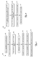
- Figure 5 is a flow chart depicting one embodiment of a method 500 of performing navigation tasks.
- Method 500 can be implemented in a system such as system 100 above.
- range data of a scene is obtained with an image sensor, such as image sensor 102.
- the range data is provided to a processing unit, such as processing unit 104.
- the processing unit optionally pre-processes the range data.
- range data originally obtained in spherical coordinates is converted to Cartesian coordinates for use by the processing unit.
- the range data can be converted by the image sensor and provided to the processing unit in Cartesian coordinates or the range data can be provided in spherical coordinates and preprocessed by the processing unit to convert the spherical range data to Cartesian coordinates.
- pre-processing the range data helps remove noise in the range data and can be performed on the spherical coordinate range data and the converted Cartesian coordinate range data.
- the processing unit performs a Gaussian blur on the range data.
- a median filter is used by the processing unit.
- plane features are identified based on the range data.
- the processing unit uses the Cartesian coordinate range data in this example.
- Fig. 6 describes more details with respect to one embodiment of identifying plane features based on the range data.
- the identified plane features are extracted or segmented using image segmentation techniques known to one of skill in the art.
- the extracted plane features are projected to a reference orientation as discussed above.
- the reference orientation is an orientation facing the image sensor.
- the projected plane features are analyzed to be used in the navigation task.
- the projected plane features are matched to corresponding plane features in a prior scene to estimate motion.
- the projected plane features are used to generate navigation maps.
- the projected plane features are integrated with map data to minimize misalignment of map data to the real world.
- Fig. 6 is a flow chart depicting one method of identifying plane features based on range data received from a 3D image sensor.
- a normal vector is calculated at each of a plurality of points in a scene for each of a plurality of scales.
- each of the calculated normal vectors is compared to a plurality of other calculated normal vectors in a neighborhood. For example, in some embodiments, the calculated normal for each point is compared to the normal vector of each of the point's neighborhood boundary points. If the difference between the orientation of a given point and the orientation of the boundary points is below a threshold, the given point is considered part of a local plane.
- the given point is not considered part of the local plane.
- four normal vectors associated with difference vectors between a given point and boundary points are calculated as described above with respect to Figs. 3A and 3B are calculated. The four normal vectors are then compared directly to determine if the given point is part of the local plane rather than deriving a normal vector at the given point for use in comparisons.
- the comparison results for each of the plurality of scales are combined to form a composite result.
- one or more identified plane features from each scale are combined with corresponding plane features from each of the other scales.
- a local maxima is detected in each of the combined plane features.
- the local maxima for each of the combined plane features is considered the center of the respective plane feature.
- the plane features and their respective centers are identified based on range data.
- All or some portions of the processing of range data described above can be implemented in software instructions tangibly embodied on a computer readable medium and executed by a processing unit such as processing unit 104.
- Such computer readable media can be any available media that can be accessed by a general purpose or special purpose computer or processor, or any programmable logic device.
- Suitable computer readable media may include storage or memory media such as magnetic or optical media, e.g., disk or CD-ROM, volatile or non-volatile media such as RAM (e.g., SDRAM, DDR SDRAM, RDRAM, SRAM, etc.), ROM, EEPROM, flash memory, etc. as well as transmission media such as electrical, electromagnetic, or digital signals, conveyed via a communication medium such as a network and/or a wireless link
Landscapes
- Engineering & Computer Science (AREA)
- Multimedia (AREA)
- Computer Vision & Pattern Recognition (AREA)
- Physics & Mathematics (AREA)
- General Physics & Mathematics (AREA)
- Theoretical Computer Science (AREA)
- Navigation (AREA)
- Image Analysis (AREA)
Applications Claiming Priority (1)
| Application Number | Priority Date | Filing Date | Title |
|---|---|---|---|
| US12/234,331 US8503730B2 (en) | 2008-09-19 | 2008-09-19 | System and method of extracting plane features |
Publications (3)
| Publication Number | Publication Date |
|---|---|
| EP2166375A2 true EP2166375A2 (de) | 2010-03-24 |
| EP2166375A3 EP2166375A3 (de) | 2011-10-05 |
| EP2166375B1 EP2166375B1 (de) | 2015-10-28 |
Family
ID=41445444
Family Applications (1)
| Application Number | Title | Priority Date | Filing Date |
|---|---|---|---|
| EP09170000.5A Active EP2166375B1 (de) | 2008-09-19 | 2009-09-10 | System und Verfahren zur Extraktion von Flugzeugmerkmalen |
Country Status (3)
| Country | Link |
|---|---|
| US (1) | US8503730B2 (de) |
| EP (1) | EP2166375B1 (de) |
| IL (1) | IL200916A (de) |
Cited By (5)
| Publication number | Priority date | Publication date | Assignee | Title |
|---|---|---|---|---|
| EP2249311A1 (de) * | 2009-05-06 | 2010-11-10 | Honeywell International Inc. | Systeme und Verfahren zur Extraktion von planaren Eigenschaften, Anpassen der planaren Eigenschaften und Beurteilung der Bewegung der planaren Eigenschaften |
| US8199977B2 (en) | 2010-05-07 | 2012-06-12 | Honeywell International Inc. | System and method for extraction of features from a 3-D point cloud |
| US8510039B1 (en) | 2010-10-05 | 2013-08-13 | The Boeing Company | Methods and apparatus for three-dimensional localization and mapping |
| US8521418B2 (en) | 2011-09-26 | 2013-08-27 | Honeywell International Inc. | Generic surface feature extraction from a set of range data |
| US9153067B2 (en) | 2013-01-21 | 2015-10-06 | Honeywell International Inc. | Systems and methods for 3D data based navigation using descriptor vectors |
Families Citing this family (9)
| Publication number | Priority date | Publication date | Assignee | Title |
|---|---|---|---|---|
| US8699755B2 (en) | 2009-02-20 | 2014-04-15 | Navteq B.V. | Determining travel path features based on retroreflectivity |
| US8660365B2 (en) * | 2010-07-29 | 2014-02-25 | Honeywell International Inc. | Systems and methods for processing extracted plane features |
| US9123165B2 (en) | 2013-01-21 | 2015-09-01 | Honeywell International Inc. | Systems and methods for 3D data based navigation using a watershed method |
| US9305364B2 (en) * | 2013-02-19 | 2016-04-05 | Caterpillar Inc. | Motion estimation systems and methods |
| US10115035B2 (en) * | 2015-01-08 | 2018-10-30 | Sungkyunkwan University Foundation For Corporation Collaboration | Vision system and analytical method for planar surface segmentation |
| CA3040599C (en) | 2016-11-29 | 2022-09-06 | Continental Automotive Gmbh | Method and system for generating environment model and for positioning using cross-sensor feature point referencing |
| US11776153B2 (en) * | 2019-10-08 | 2023-10-03 | Zebra Technologies Corporation | Method, system and apparatus for mobile dimensioning |
| CN112488215B (zh) * | 2020-12-04 | 2024-06-18 | 广东电网有限责任公司 | 一种电缆沟点云自动分类方法 |
| US12190520B2 (en) | 2022-07-05 | 2025-01-07 | Alibaba (China) Co., Ltd. | Pyramid architecture for multi-scale processing in point cloud segmentation |
Family Cites Families (9)
| Publication number | Priority date | Publication date | Assignee | Title |
|---|---|---|---|---|
| US4891630A (en) * | 1988-04-22 | 1990-01-02 | Friedman Mark B | Computer vision system with improved object orientation technique |
| US5383013A (en) * | 1992-09-18 | 1995-01-17 | Nec Research Institute, Inc. | Stereoscopic computer vision system |
| JP3263724B2 (ja) * | 1993-04-16 | 2002-03-11 | 日本電信電話株式会社 | 2次元レーザパターンによる形状特徴抽出装置 |
| WO2001008098A1 (en) | 1999-07-21 | 2001-02-01 | Obvious Technology, Inc. | Object extraction in images |
| US7203342B2 (en) * | 2001-03-07 | 2007-04-10 | Schlumberger Technology Corporation | Image feature extraction |
| US6911995B2 (en) * | 2001-08-17 | 2005-06-28 | Mitsubishi Electric Research Labs, Inc. | Computer vision depth segmentation using virtual surface |
| US7340098B2 (en) * | 2006-03-15 | 2008-03-04 | Matsushita Electric Industrial Co., Ltd. | Method and apparatus for image conversion |
| JP4196302B2 (ja) * | 2006-06-19 | 2008-12-17 | ソニー株式会社 | 情報処理装置および方法、並びにプログラム |
| US8605947B2 (en) * | 2008-04-24 | 2013-12-10 | GM Global Technology Operations LLC | Method for detecting a clear path of travel for a vehicle enhanced by object detection |
-
2008
- 2008-09-19 US US12/234,331 patent/US8503730B2/en active Active
-
2009
- 2009-09-10 EP EP09170000.5A patent/EP2166375B1/de active Active
- 2009-09-14 IL IL200916A patent/IL200916A/en active IP Right Grant
Non-Patent Citations (2)
| Title |
|---|
| PFISTER, T.S.; BURDICK, J.W.: "Multi-scale point and line range data algorithms for mapping and localisation", PROCEEDINGS OF THE 2006 IEEE INTERNATIONAL CONFERENCE ON ROBOTICS AND AUTOMATION, 15 May 2006 (2006-05-15), pages 1159 - 1166 |
| UIJT DE HAAG, M: "Implementation of a flash-LADAR aided inertial navigator", LOCATION AND NAVIGATION SYMPOSIUM, 5 May 2008 (2008-05-05), pages 560 - 567 |
Cited By (6)
| Publication number | Priority date | Publication date | Assignee | Title |
|---|---|---|---|---|
| EP2249311A1 (de) * | 2009-05-06 | 2010-11-10 | Honeywell International Inc. | Systeme und Verfahren zur Extraktion von planaren Eigenschaften, Anpassen der planaren Eigenschaften und Beurteilung der Bewegung der planaren Eigenschaften |
| US8340400B2 (en) | 2009-05-06 | 2012-12-25 | Honeywell International Inc. | Systems and methods for extracting planar features, matching the planar features, and estimating motion from the planar features |
| US8199977B2 (en) | 2010-05-07 | 2012-06-12 | Honeywell International Inc. | System and method for extraction of features from a 3-D point cloud |
| US8510039B1 (en) | 2010-10-05 | 2013-08-13 | The Boeing Company | Methods and apparatus for three-dimensional localization and mapping |
| US8521418B2 (en) | 2011-09-26 | 2013-08-27 | Honeywell International Inc. | Generic surface feature extraction from a set of range data |
| US9153067B2 (en) | 2013-01-21 | 2015-10-06 | Honeywell International Inc. | Systems and methods for 3D data based navigation using descriptor vectors |
Also Published As
| Publication number | Publication date |
|---|---|
| US20100074473A1 (en) | 2010-03-25 |
| EP2166375B1 (de) | 2015-10-28 |
| US8503730B2 (en) | 2013-08-06 |
| EP2166375A3 (de) | 2011-10-05 |
| IL200916A (en) | 2014-02-27 |
| IL200916A0 (en) | 2010-06-16 |
Similar Documents
| Publication | Publication Date | Title |
|---|---|---|
| EP2166375B1 (de) | System und Verfahren zur Extraktion von Flugzeugmerkmalen | |
| CN111326023B (zh) | 一种无人机航线预警方法、装置、设备及存储介质 | |
| US8199977B2 (en) | System and method for extraction of features from a 3-D point cloud | |
| EP2711670B1 (de) | Visuelle Lokalisierung | |
| EP2249311B1 (de) | Systeme und Verfahren zur Extraktion von planaren Eigenschaften, Anpassen der planaren Eigenschaften und Beurteilung der Bewegung der planaren Eigenschaften | |
| EP2615580B1 (de) | Automatische Szenenkalibrierung | |
| KR101633620B1 (ko) | 영상 기반의 위치 인식을 위한 특징점 등록 장치 및 그 방법 | |
| US9082008B2 (en) | System and methods for feature selection and matching | |
| EP2874097A2 (de) | Automatisches Szenenparsing | |
| CN114004977B (zh) | 一种基于深度学习的航拍数据目标定位方法及系统 | |
| EP3552388B1 (de) | Durch merkmalserkennung assistiertes hochauflösendes verfahren | |
| CN110807350A (zh) | 用于面向扫描匹配的视觉slam的系统和方法 | |
| CN113537047A (zh) | 障碍物检测方法、装置、交通工具及存储介质 | |
| Chen et al. | Drogue tracking using 3D flash lidar for autonomous aerial refueling | |
| CN113723432B (zh) | 一种基于深度学习的智能识别、定位追踪的方法及系统 | |
| CN121053194A (zh) | 一种基于无源定位的火场面积快速估算方法 | |
| CN111553342B (zh) | 一种视觉定位方法、装置、计算机设备和存储介质 | |
| CN113447032A (zh) | 定位方法、装置、电子设备及存储介质 | |
| US12000703B2 (en) | Method, software product, and system for determining a position and orientation in a 3D reconstruction of the earth's surface | |
| US12296488B2 (en) | Method and system to detect and estimate dynamic obstacles using RGB-D sensors for robot navigation | |
| JP7207479B2 (ja) | 建築限界判定方法 | |
| CN117057086A (zh) | 基于目标识别与模型匹配的三维重建方法、装置及设备 | |
| CN113011212A (zh) | 图像识别方法、装置及车辆 | |
| EP4528221A1 (de) | Verfahren, systeme und computerprogrammprodukte zur georeferenzierung von bilddaten | |
| Sehgal et al. | Pose estimation and trajectory derivation from underwater imagery |
Legal Events
| Date | Code | Title | Description |
|---|---|---|---|
| PUAI | Public reference made under article 153(3) epc to a published international application that has entered the european phase |
Free format text: ORIGINAL CODE: 0009012 |
|
| 17P | Request for examination filed |
Effective date: 20090910 |
|
| AK | Designated contracting states |
Kind code of ref document: A2 Designated state(s): AT BE BG CH CY CZ DE DK EE ES FI FR GB GR HR HU IE IS IT LI LT LU LV MC MK MT NL NO PL PT RO SE SI SK SM TR |
|
| AX | Request for extension of the european patent |
Extension state: AL BA RS |
|
| PUAL | Search report despatched |
Free format text: ORIGINAL CODE: 0009013 |
|
| AK | Designated contracting states |
Kind code of ref document: A3 Designated state(s): AT BE BG CH CY CZ DE DK EE ES FI FR GB GR HR HU IE IS IT LI LT LU LV MC MK MT NL NO PL PT RO SE SI SK SM TR |
|
| AX | Request for extension of the european patent |
Extension state: AL BA RS |
|
| RIC1 | Information provided on ipc code assigned before grant |
Ipc: G01C 21/00 20060101ALI20110830BHEP Ipc: G06T 7/20 20060101ALI20110830BHEP Ipc: G01S 17/89 20060101AFI20110830BHEP Ipc: G01S 17/02 20060101ALI20110830BHEP |
|
| 17Q | First examination report despatched |
Effective date: 20111006 |
|
| GRAP | Despatch of communication of intention to grant a patent |
Free format text: ORIGINAL CODE: EPIDOSNIGR1 |
|
| INTG | Intention to grant announced |
Effective date: 20150724 |
|
| GRAS | Grant fee paid |
Free format text: ORIGINAL CODE: EPIDOSNIGR3 |
|
| GRAA | (expected) grant |
Free format text: ORIGINAL CODE: 0009210 |
|
| AK | Designated contracting states |
Kind code of ref document: B1 Designated state(s): AT BE BG CH CY CZ DE DK EE ES FI FR GB GR HR HU IE IS IT LI LT LU LV MC MK MT NL NO PL PT RO SE SI SK SM TR |
|
| REG | Reference to a national code |
Ref country code: GB Ref legal event code: FG4D |
|
| REG | Reference to a national code |
Ref country code: CH Ref legal event code: EP |
|
| REG | Reference to a national code |
Ref country code: AT Ref legal event code: REF Ref document number: 758234 Country of ref document: AT Kind code of ref document: T Effective date: 20151115 |
|
| REG | Reference to a national code |
Ref country code: IE Ref legal event code: FG4D |
|
| REG | Reference to a national code |
Ref country code: DE Ref legal event code: R096 Ref document number: 602009034454 Country of ref document: DE |
|
| RAP2 | Party data changed (patent owner data changed or rights of a patent transferred) |
Owner name: HONEYWELL INTERNATIONAL INC. |
|
| REG | Reference to a national code |
Ref country code: LT Ref legal event code: MG4D |
|
| REG | Reference to a national code |
Ref country code: NL Ref legal event code: MP Effective date: 20151028 |
|
| REG | Reference to a national code |
Ref country code: AT Ref legal event code: MK05 Ref document number: 758234 Country of ref document: AT Kind code of ref document: T Effective date: 20151028 |
|
| PG25 | Lapsed in a contracting state [announced via postgrant information from national office to epo] |
Ref country code: IT Free format text: LAPSE BECAUSE OF FAILURE TO SUBMIT A TRANSLATION OF THE DESCRIPTION OR TO PAY THE FEE WITHIN THE PRESCRIBED TIME-LIMIT Effective date: 20151028 Ref country code: NO Free format text: LAPSE BECAUSE OF FAILURE TO SUBMIT A TRANSLATION OF THE DESCRIPTION OR TO PAY THE FEE WITHIN THE PRESCRIBED TIME-LIMIT Effective date: 20160128 Ref country code: HR Free format text: LAPSE BECAUSE OF FAILURE TO SUBMIT A TRANSLATION OF THE DESCRIPTION OR TO PAY THE FEE WITHIN THE PRESCRIBED TIME-LIMIT Effective date: 20151028 Ref country code: IS Free format text: LAPSE BECAUSE OF FAILURE TO SUBMIT A TRANSLATION OF THE DESCRIPTION OR TO PAY THE FEE WITHIN THE PRESCRIBED TIME-LIMIT Effective date: 20160228 Ref country code: LT Free format text: LAPSE BECAUSE OF FAILURE TO SUBMIT A TRANSLATION OF THE DESCRIPTION OR TO PAY THE FEE WITHIN THE PRESCRIBED TIME-LIMIT Effective date: 20151028 Ref country code: ES Free format text: LAPSE BECAUSE OF FAILURE TO SUBMIT A TRANSLATION OF THE DESCRIPTION OR TO PAY THE FEE WITHIN THE PRESCRIBED TIME-LIMIT Effective date: 20151028 Ref country code: NL Free format text: LAPSE BECAUSE OF FAILURE TO SUBMIT A TRANSLATION OF THE DESCRIPTION OR TO PAY THE FEE WITHIN THE PRESCRIBED TIME-LIMIT Effective date: 20151028 |
|
| PG25 | Lapsed in a contracting state [announced via postgrant information from national office to epo] |
Ref country code: PT Free format text: LAPSE BECAUSE OF FAILURE TO SUBMIT A TRANSLATION OF THE DESCRIPTION OR TO PAY THE FEE WITHIN THE PRESCRIBED TIME-LIMIT Effective date: 20160229 Ref country code: FI Free format text: LAPSE BECAUSE OF FAILURE TO SUBMIT A TRANSLATION OF THE DESCRIPTION OR TO PAY THE FEE WITHIN THE PRESCRIBED TIME-LIMIT Effective date: 20151028 Ref country code: GR Free format text: LAPSE BECAUSE OF FAILURE TO SUBMIT A TRANSLATION OF THE DESCRIPTION OR TO PAY THE FEE WITHIN THE PRESCRIBED TIME-LIMIT Effective date: 20160129 Ref country code: PL Free format text: LAPSE BECAUSE OF FAILURE TO SUBMIT A TRANSLATION OF THE DESCRIPTION OR TO PAY THE FEE WITHIN THE PRESCRIBED TIME-LIMIT Effective date: 20151028 Ref country code: AT Free format text: LAPSE BECAUSE OF FAILURE TO SUBMIT A TRANSLATION OF THE DESCRIPTION OR TO PAY THE FEE WITHIN THE PRESCRIBED TIME-LIMIT Effective date: 20151028 Ref country code: LV Free format text: LAPSE BECAUSE OF FAILURE TO SUBMIT A TRANSLATION OF THE DESCRIPTION OR TO PAY THE FEE WITHIN THE PRESCRIBED TIME-LIMIT Effective date: 20151028 Ref country code: SE Free format text: LAPSE BECAUSE OF FAILURE TO SUBMIT A TRANSLATION OF THE DESCRIPTION OR TO PAY THE FEE WITHIN THE PRESCRIBED TIME-LIMIT Effective date: 20151028 |
|
| PG25 | Lapsed in a contracting state [announced via postgrant information from national office to epo] |
Ref country code: CZ Free format text: LAPSE BECAUSE OF FAILURE TO SUBMIT A TRANSLATION OF THE DESCRIPTION OR TO PAY THE FEE WITHIN THE PRESCRIBED TIME-LIMIT Effective date: 20151028 |
|
| REG | Reference to a national code |
Ref country code: DE Ref legal event code: R097 Ref document number: 602009034454 Country of ref document: DE |
|
| PG25 | Lapsed in a contracting state [announced via postgrant information from national office to epo] |
Ref country code: DK Free format text: LAPSE BECAUSE OF FAILURE TO SUBMIT A TRANSLATION OF THE DESCRIPTION OR TO PAY THE FEE WITHIN THE PRESCRIBED TIME-LIMIT Effective date: 20151028 Ref country code: RO Free format text: LAPSE BECAUSE OF FAILURE TO SUBMIT A TRANSLATION OF THE DESCRIPTION OR TO PAY THE FEE WITHIN THE PRESCRIBED TIME-LIMIT Effective date: 20151028 Ref country code: SM Free format text: LAPSE BECAUSE OF FAILURE TO SUBMIT A TRANSLATION OF THE DESCRIPTION OR TO PAY THE FEE WITHIN THE PRESCRIBED TIME-LIMIT Effective date: 20151028 Ref country code: EE Free format text: LAPSE BECAUSE OF FAILURE TO SUBMIT A TRANSLATION OF THE DESCRIPTION OR TO PAY THE FEE WITHIN THE PRESCRIBED TIME-LIMIT Effective date: 20151028 Ref country code: SK Free format text: LAPSE BECAUSE OF FAILURE TO SUBMIT A TRANSLATION OF THE DESCRIPTION OR TO PAY THE FEE WITHIN THE PRESCRIBED TIME-LIMIT Effective date: 20151028 |
|
| PLBE | No opposition filed within time limit |
Free format text: ORIGINAL CODE: 0009261 |
|
| STAA | Information on the status of an ep patent application or granted ep patent |
Free format text: STATUS: NO OPPOSITION FILED WITHIN TIME LIMIT |
|
| 26N | No opposition filed |
Effective date: 20160729 |
|
| PG25 | Lapsed in a contracting state [announced via postgrant information from national office to epo] |
Ref country code: SI Free format text: LAPSE BECAUSE OF FAILURE TO SUBMIT A TRANSLATION OF THE DESCRIPTION OR TO PAY THE FEE WITHIN THE PRESCRIBED TIME-LIMIT Effective date: 20151028 |
|
| PG25 | Lapsed in a contracting state [announced via postgrant information from national office to epo] |
Ref country code: BE Free format text: LAPSE BECAUSE OF FAILURE TO SUBMIT A TRANSLATION OF THE DESCRIPTION OR TO PAY THE FEE WITHIN THE PRESCRIBED TIME-LIMIT Effective date: 20151028 |
|
| PG25 | Lapsed in a contracting state [announced via postgrant information from national office to epo] |
Ref country code: MC Free format text: LAPSE BECAUSE OF FAILURE TO SUBMIT A TRANSLATION OF THE DESCRIPTION OR TO PAY THE FEE WITHIN THE PRESCRIBED TIME-LIMIT Effective date: 20151028 |
|
| REG | Reference to a national code |
Ref country code: CH Ref legal event code: PL |
|
| REG | Reference to a national code |
Ref country code: IE Ref legal event code: MM4A |
|
| REG | Reference to a national code |
Ref country code: FR Ref legal event code: ST Effective date: 20170531 |
|
| PG25 | Lapsed in a contracting state [announced via postgrant information from national office to epo] |
Ref country code: LI Free format text: LAPSE BECAUSE OF NON-PAYMENT OF DUE FEES Effective date: 20160930 Ref country code: FR Free format text: LAPSE BECAUSE OF NON-PAYMENT OF DUE FEES Effective date: 20160930 Ref country code: IE Free format text: LAPSE BECAUSE OF NON-PAYMENT OF DUE FEES Effective date: 20160910 Ref country code: CH Free format text: LAPSE BECAUSE OF NON-PAYMENT OF DUE FEES Effective date: 20160930 |
|
| PG25 | Lapsed in a contracting state [announced via postgrant information from national office to epo] |
Ref country code: LU Free format text: LAPSE BECAUSE OF NON-PAYMENT OF DUE FEES Effective date: 20160910 |
|
| PG25 | Lapsed in a contracting state [announced via postgrant information from national office to epo] |
Ref country code: HU Free format text: LAPSE BECAUSE OF FAILURE TO SUBMIT A TRANSLATION OF THE DESCRIPTION OR TO PAY THE FEE WITHIN THE PRESCRIBED TIME-LIMIT; INVALID AB INITIO Effective date: 20090910 Ref country code: CY Free format text: LAPSE BECAUSE OF FAILURE TO SUBMIT A TRANSLATION OF THE DESCRIPTION OR TO PAY THE FEE WITHIN THE PRESCRIBED TIME-LIMIT Effective date: 20151028 |
|
| PG25 | Lapsed in a contracting state [announced via postgrant information from national office to epo] |
Ref country code: TR Free format text: LAPSE BECAUSE OF FAILURE TO SUBMIT A TRANSLATION OF THE DESCRIPTION OR TO PAY THE FEE WITHIN THE PRESCRIBED TIME-LIMIT Effective date: 20151028 Ref country code: MK Free format text: LAPSE BECAUSE OF FAILURE TO SUBMIT A TRANSLATION OF THE DESCRIPTION OR TO PAY THE FEE WITHIN THE PRESCRIBED TIME-LIMIT Effective date: 20151028 Ref country code: MT Free format text: LAPSE BECAUSE OF NON-PAYMENT OF DUE FEES Effective date: 20160930 |
|
| PG25 | Lapsed in a contracting state [announced via postgrant information from national office to epo] |
Ref country code: BG Free format text: LAPSE BECAUSE OF FAILURE TO SUBMIT A TRANSLATION OF THE DESCRIPTION OR TO PAY THE FEE WITHIN THE PRESCRIBED TIME-LIMIT Effective date: 20151028 |
|
| P01 | Opt-out of the competence of the unified patent court (upc) registered |
Effective date: 20230525 |
|
| PGFP | Annual fee paid to national office [announced via postgrant information from national office to epo] |
Ref country code: DE Payment date: 20250926 Year of fee payment: 17 |
|
| PGFP | Annual fee paid to national office [announced via postgrant information from national office to epo] |
Ref country code: GB Payment date: 20250923 Year of fee payment: 17 |