EP2165959A1 - Enrouleur dérouleur pour tuyau de lance d'incendie - Google Patents
Enrouleur dérouleur pour tuyau de lance d'incendie Download PDFInfo
- Publication number
- EP2165959A1 EP2165959A1 EP09170090A EP09170090A EP2165959A1 EP 2165959 A1 EP2165959 A1 EP 2165959A1 EP 09170090 A EP09170090 A EP 09170090A EP 09170090 A EP09170090 A EP 09170090A EP 2165959 A1 EP2165959 A1 EP 2165959A1
- Authority
- EP
- European Patent Office
- Prior art keywords
- braking
- frame
- reel
- transverse
- lateral
- Prior art date
- Legal status (The legal status is an assumption and is not a legal conclusion. Google has not performed a legal analysis and makes no representation as to the accuracy of the status listed.)
- Granted
Links
- 238000005096 rolling process Methods 0.000 claims description 4
- 241000282414 Homo sapiens Species 0.000 claims description 2
- 239000007787 solid Substances 0.000 abstract description 3
- 230000000295 complement effect Effects 0.000 description 3
- 239000000463 material Substances 0.000 description 2
- 230000001419 dependent effect Effects 0.000 description 1
- 238000006073 displacement reaction Methods 0.000 description 1
- 230000035939 shock Effects 0.000 description 1
- 239000004753 textile Substances 0.000 description 1
- XLYOFNOQVPJJNP-UHFFFAOYSA-N water Substances O XLYOFNOQVPJJNP-UHFFFAOYSA-N 0.000 description 1
- 238000004804 winding Methods 0.000 description 1
Images


Classifications
-
- B—PERFORMING OPERATIONS; TRANSPORTING
- B65—CONVEYING; PACKING; STORING; HANDLING THIN OR FILAMENTARY MATERIAL
- B65H—HANDLING THIN OR FILAMENTARY MATERIAL, e.g. SHEETS, WEBS, CABLES
- B65H75/00—Storing webs, tapes, or filamentary material, e.g. on reels
- B65H75/02—Cores, formers, supports, or holders for coiled, wound, or folded material, e.g. reels, spindles, bobbins, cop tubes, cans, mandrels or chucks
- B65H75/34—Cores, formers, supports, or holders for coiled, wound, or folded material, e.g. reels, spindles, bobbins, cop tubes, cans, mandrels or chucks specially adapted or mounted for storing and repeatedly paying-out and re-storing lengths of material provided for particular purposes, e.g. anchored hoses, power cables
- B65H75/38—Cores, formers, supports, or holders for coiled, wound, or folded material, e.g. reels, spindles, bobbins, cop tubes, cans, mandrels or chucks specially adapted or mounted for storing and repeatedly paying-out and re-storing lengths of material provided for particular purposes, e.g. anchored hoses, power cables involving the use of a core or former internal to, and supporting, a stored package of material
- B65H75/44—Constructional details
- B65H75/4478—Constructional details relating to handling of fluids
-
- B—PERFORMING OPERATIONS; TRANSPORTING
- B65—CONVEYING; PACKING; STORING; HANDLING THIN OR FILAMENTARY MATERIAL
- B65H—HANDLING THIN OR FILAMENTARY MATERIAL, e.g. SHEETS, WEBS, CABLES
- B65H75/00—Storing webs, tapes, or filamentary material, e.g. on reels
- B65H75/02—Cores, formers, supports, or holders for coiled, wound, or folded material, e.g. reels, spindles, bobbins, cop tubes, cans, mandrels or chucks
- B65H75/34—Cores, formers, supports, or holders for coiled, wound, or folded material, e.g. reels, spindles, bobbins, cop tubes, cans, mandrels or chucks specially adapted or mounted for storing and repeatedly paying-out and re-storing lengths of material provided for particular purposes, e.g. anchored hoses, power cables
- B65H75/38—Cores, formers, supports, or holders for coiled, wound, or folded material, e.g. reels, spindles, bobbins, cop tubes, cans, mandrels or chucks specially adapted or mounted for storing and repeatedly paying-out and re-storing lengths of material provided for particular purposes, e.g. anchored hoses, power cables involving the use of a core or former internal to, and supporting, a stored package of material
- B65H75/40—Cores, formers, supports, or holders for coiled, wound, or folded material, e.g. reels, spindles, bobbins, cop tubes, cans, mandrels or chucks specially adapted or mounted for storing and repeatedly paying-out and re-storing lengths of material provided for particular purposes, e.g. anchored hoses, power cables involving the use of a core or former internal to, and supporting, a stored package of material mobile or transportable
- B65H75/403—Carriage with wheels
-
- B—PERFORMING OPERATIONS; TRANSPORTING
- B65—CONVEYING; PACKING; STORING; HANDLING THIN OR FILAMENTARY MATERIAL
- B65H—HANDLING THIN OR FILAMENTARY MATERIAL, e.g. SHEETS, WEBS, CABLES
- B65H2701/00—Handled material; Storage means
- B65H2701/30—Handled filamentary material
- B65H2701/33—Hollow or hose-like material
- B65H2701/332—Flattened hoses
Definitions
- the present invention relates to a winder hose reel for fire hose, used by firefighters, to extinguish fires.
- the unwinding reel of the invention will be designated later by mobile reel which is the name commonly used by firefighters.
- Such mobile reels are already known which are transported by a vehicle and which once near the place of the fire are disconnected from the vehicle to be put on the ground, while the pipe is unrolled to be used.
- the invention proposes an improvement significantly improving traditional reels.
- the mobile reel for fire hose comprises a frame on which is mounted in rotation about a transverse axis a coil for receiving the pipe, and comprising a set of two wheels ensuring the displacement by rolling reel, and is characterized in that it comprises braking means.
- the reel comprises means for braking a so-called “dead man” device.
- the frame consists of a lower part constituting the support of the coil, and an upper part constituting the gripping means, while said frame comprises two lateral stands which are constituted by parts of support fixed on the lateral flanks of the lower part of the frame, said support pieces extending over such a length in the tilted position on the ground, the support of the crutches on the ground places the gripper so that its transverse grip is not on the ground.
- the braking means constituted by a brake caliper mounted and pivoted on the frame, said yoke having the shape of a "U" reversed, and is constituted by two lateral branches whose upper ends are connected by a transverse arm of brake control, while the lateral branches are extended downward beyond the pivot axis of the brake caliper by braking extensions each carrying at their respective ends, a braking pad intended to bear on the tire of the corresponding wheel.
- the brake caliper is held in the braking position by at least one elastic system, while the system comprises a locking system of the non-braking position, consisting of a pivoting latch mounted on a transverse arm. brake control, for locking the brake caliper relative to the chassis.
- the reel (1) of the invention comprises a frame (2) on which is mounted in rotation about a transverse axis (X, X '), a coil (3) for receiving the pipe. On the chassis is also mounted a wheel train as we will see later in the description.
- the pipe (not shown) comprises at its free end a water release valve, to form the fire hose.
- the coil (3) is constituted by two lateral flanges (30a, 30b), connected by a central axis (31), for supporting the pipe.
- the latter which is deformable material, such as textile, is flattened in its non-use position and in particular when it is wound on the spool.
- the frame (2) consists of a lower part (20) constituting the support of the coil, and an upper part (21) constituting the gripping means.
- the mobile reel (1) is as its name suggests moving, moving, or to be moved.
- the chassis (2) comprises rolling means consisting of a rolling train comprising two lateral wheels (4a, 4b) whose diameter and position allow, on the one hand, the free movement of the reel, and on the other hand, the free rotation of the coil to allow winding and unwinding of the pipe.
- the lower part (20) of the frame (2) is an inverted "U" shaped yoke, comprising two downwardly extending lateral flanks (5a, 5b), which are connected by a horizontal cross member (5c), while the upper part (31) of the frame (2) consists of two upwardly extending lateral arms (7a, 7b) connected at their upper part by a horizontal transverse gripping branch (7c).
- the frame (2) of the mobile reel of the invention comprises two side stands (12a, 12b) which are constituted by support pieces fixed on the lateral sides of the lower part of the frame. These support pieces extend over a length such that in the tilted position on the ground, the support of the crutches places the gripper so that its transverse gripping arm is not on the ground. Thus, the user can easily apprehend the gripping branch through the space (E) formed between said gripping arm and the ground (S).
- the mobile reel (1) comprises braking means.
- These means are constituted by a brake caliper (9) pivotally mounted on the frame (2).
- This stirrup which constitutes the brake control member, has the shape of an inverted "U", and is constituted by two lateral branches (9a, 9b) whose upper ends are connected by a transverse braking control arm. (9c).
- the side branches (9a, 9b) are extended downwardly beyond the pivot axis of the brake caliper (Y, Y ') by braking extensions (9d, 9e) each bearing their respective respective end, a braking pad (12a, 12b) intended to bear against the tire of the corresponding wheel.
- Each of the braking pads is constituted by a sleeve made of deformable material and mounted on a rod comprising at its end a adjusting nut. This makes it possible to crush the brake sleeve in order to adjust the braking performance.
- the brake caliper (9) is held in the braking position by at least one elastic system.
- two lateral springs (10a, 10b) are provided. These springs are, for example, traction springs whose one end is fixed on the lateral side of the frame, while the other end is fixed on the corresponding braking extension.
- the tires of the wheels (4d, 4c) are advantageously solid tires, so that the users do not have any problem of inflation and / or puncture.
- having solid tires allows braking reliability, which would not be the case with tires requiring inflation, because in this case the braking would be dependent on the inflation.
Landscapes
- Braking Arrangements (AREA)
- Storing, Repeated Paying-Out, And Re-Storing Of Elongated Articles (AREA)
- Refinement Of Pig-Iron, Manufacture Of Cast Iron, And Steel Manufacture Other Than In Revolving Furnaces (AREA)
Abstract
Description
- La présente invention concerne un enrouleur dérouleur pour tuyaux de lance d'incendie, utilisé par les pompiers, pour éteindre les feux. L'enrouleur dérouleur de l'invention sera désigné par la suite par dévidoir mobile qui est l'appellation couramment utilisée par les pompiers.
- On connaît déjà de tels dévidoirs mobiles qui sont transportés par un véhicule et qui une fois à proximité du lieu de l'incendie sont déconnectés du véhicule pour être mis au sol, alors que le tuyau est déroulé pour être utilisé.
- L'invention propose un perfectionnement améliorant de façon significative les dévidoirs traditionnels.
- Ainsi, le dévidoir mobile pour tuyau de lance d'incendie, selon l'invention comprend un châssis sur lequel est monté en rotation autour d'un axe transversal une bobine destinée à recevoir le tuyau, et comprenant un ensemble deux roues assurant le déplacement par roulement du dévidoir, et est caractérisé en ce qu'il comprend des moyens de freinage.
- Selon une caractéristique complémentaire le dévidoir comprend des moyens de freinage un dispositif dit "homme mort".
- Selon une autre caractéristique complémentaire, le châssis est constitué d'une partie basse constituant le support de la bobine, et d'une partie haute constituant les moyens de préhension, tandis que ledit châssis comprend deux béquilles latérales qui sont constituées par des pièces d'appui fixées sur les flancs latéraux de la partie basse du châssis, ces dites pièces d'appui s'étendant sur une longueur telle qu'en position basculée sur le sol, l'appui des béquilles sur le sol place l'étrier de préhension de façon à ce que sa branche transversale de préhension ne soit pas sur le sol.
- Ajoutons que les moyens de freinage constitués par un étrier de freinage monté et pivotant sur le châssis, ledit étrier ayant la forme d'un "U" renversé, et est constitué par deux branches latérales dont les extrémités supérieures sont reliées par un bras transversal de commande de freinage, tandis que les branches latérales sont prolongées vers le bas au-delà de l'axe de pivotement de l'étrier de freinage par des prolongements de freinage portant chacune à leur extrémité respective, un patin de freinage destiné à venir en appui sur le pneu de la roue correspondante.
- Selon d'autres caractéristiques complémentaires, l'étrier de freinage est maintenu en position de freinage par au moins un système élastique, tandis que le comprend un système de verrouillage de la position de non freinage, constitué par un verrou pivotant monté sur bras transversal de commande de freinage, destiné à verrouiller l'étrier de freinage par rapport au châssis.
- D'autres caractéristiques et avantages de l'invention se dégageront de la description qui va suivre en regard des dessins annexés qui ne sont donnés qu'à titre d'exemples non limitatifs.
- La
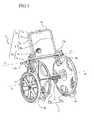
figure 1 est une vue en perspective du dévidoir de l'invention. - La
figure 2 est une vue latérale du dévidoir, son frein étant en position inactive de non freinage. - La
figure 3 est une vue latérale du dévidoir, son frein étant dans sa position active de freinage. - La
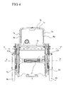
figure 4 est une vue selon F de lafigure 3 . - La
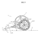
figure 5 est une vue latérale du dévidoir étant dans sa position basculée sur le sol. - La
figure 6 est une vue de détail montrant l'étrier de freinage. - La
figure 7 est une vue de détail illustrant le verrou pivotant destiné à verrouiller l'étrier de freinage dans sa position inactive. - Le dévidoir (1) de l'invention comprend un châssis (2) sur lequel est monté en rotation autour d'un axe transversal (X, X'), une bobine (3) destinée à recevoir le tuyau. Sur le châssis est aussi monté un train de roue comme nous le verrons plus loin dans la description. Le tuyau (non représenté) comprend à son extrémité libre une vanne de libération de l'eau, pour constituer la lance d'incendie.
- La bobine (3) est constituée par deux flasques latéraux (30a, 30b), reliés par un axe central (31), destiné à supporter le tuyau. Ce dernier qui est en matériau déformable, tel qu'en textile, est aplati dans sa position de non utilisation et notamment lorsqu'il est enroulé sur la bobine.
- Le châssis (2) est constitué d'une partie basse (20) constituant le support de la bobine, et d'une partie haute (21) constituant les moyens de préhension.
- Le dévidoir mobile (1) est comme son nom l'indique mobile, en déplacement, ou pour pouvoir être déplacé. A cet effet le châssis (2) comprend des moyens de roulement constitués d'un train de roulage comprenant deux roues latérales (4a, 4b) dont le diamètre et la position permettent, d'une part, le déplacement libre du dévidoir, et d'autre part, la rotation libre de la bobine afin de permettre l'enroulement et le déroulement du tuyau.
- La partie basse (20) du châssis (2) est un étrier en forme de "U" renversé, comprenant deux flans latéraux (5a, 5b) ) s'étendant vers le bas, qui sont reliés par une traverse horizontale (5c), tandis que la partie haute (31) du châssis (2) est constituée par deux bras latéraux s'étendant vers le haut (7a, 7b) reliés à leur partie supérieure par une branche transversale horizontale de préhension (7c).
- Le châssis (2) du dévidoir mobile de l'invention comprend deux béquilles latérales (12a, 12b) qui sont constituées par des pièces d'appui fixées sur le flancs latéraux de la partie basse du châssis. Ces pièces d'appui s'étendent sur une longueur telle qu'en position basculée sur le sol, l'appui des béquilles place l'étrier de préhension de façon à ce que sa branche transversale de préhension ne soit pas sur le sol. Ainsi, l'utilisateur pourra aisément appréhender la branche de préhension grâce à l'espace (E) ménagé entre ladite branche de préhension et le sol (S).
- Par ailleurs le dévidoir mobile (1) comprend des moyens de freinage. Ces moyens sont constitués par un étrier de freinage (9) monté pivotant sur le châssis (2). Cet étrier, qui constitue l'organe de commande du freinage, a la forme d'un "U" renversé, et est constitué par deux branches latérales (9a, 9b) dont les extrémités supérieures sont reliées par un bras transversal de commande de freinage (9c). Notons que les branches latérales (9a, 9b) sont prolongées vers le bas au-delà de l'axe de pivotement de l'étrier de freinage (Y, Y') par des prolongements de freinage (9d, 9e) portant chacune à leur extrémité respective, un patin de freinage (12a, 12b) destiné à venir en appui sur le pneu de la roue correspondante. Chacun des patins de freinage est constitué par une douille réalisée en matériau déformable et montée sur une tige comprenant à son extrémité un écrou de réglage. Celui-ci permet de solliciter en écrasement la douille de freinage, afin de régler les performance du freinage. Notons que l'étrier de freinage (9) est maintenu en position de freinage par au moins un système élastique. Ainsi, deux ressorts latéraux (10a, 10b) sont prévus. Ces ressorts sont, par exemple, des ressorts de traction dont l'une des extrémités est fixée sur le flanc latéral du châssis, tandis que l'autre extrémité est fixée sur le prolongement de freinage correspondant.
- Le dévidoir mobile (1) de l'invention comprend selon l'invention, un système de verrouillage de la position de non freinage. Ce système est constitué par un verrou pivotant (11) monté sur bras transversal de commande de freinage (9c), destiné à verrouiller l'étrier de freinage par rapport au châssis (2). Ledit verrou pivotant (11) peut prendre deux positions, à savoir :
- une position de verrouillage selon laquelle l'étrier de freinage est mis et verrouillé par rapport au châssis dans sa position de non freinage. Position selon laquelle les patins de freinage ne sont plus en appui sur les pneus.
et - une position de libération selon laquelle l'étrier de freinage est activé en position de freinage grâce à l'action des ressorts de traction. Position selon laquelle les patins de freinage sont mis en appui sur les pneus pour assurer le freinage du dévidoir.
- L'utilisateur, pour déplacer le dévidoir, agrippera avec sa ou ses mains, à la fois le bras transversal de commande de freinage (9c) et la branche transversale de préhension (7c), et ce pour rapprocher le bras de commande de freinage de la branche de préhension, et de les tenir en position rapprochée. S'il arrive que le dévidoir échappe à son utilisateur, le rapprochement du bras de commande de freinage avec la branche de préhension, ne sera pas maintenu puisque les ressorts (12a, 12b) solliciteront l'étrier de freinage dans la position de freinage. Ce qui présente une grande sécurité d'utilisation.
- On notera aussi que si le verrou (11) est en position de verrouillage du bras de commande de frein en position de non freinage, le simple choc des béquilles (13a, 13b) provoquera sa libération et le dispositif se placera en position de freinage. Ce qui est aussi une grande sécurité pour l'utilisateur.
- On notera que les pneus des roues (4d, 4c) sont avantageusement des pneus pleins, afin que les utilisateurs n'aient pas de problème de gonflage et/ou de crevaison. De plus le fait d'avoir des pneus pleins permet une fiabilité du freinage, ce qui ne serait pas le cas avec des pneus nécessitant un gonflage, car dans ce cas le freinage serait dépendant du gonflage.
- Bien entendu, l'invention n'est pas limitée aux modes de réalisation décrits et représentés à titre d'exemples, mais elle comprend aussi tous les équivalents techniques ainsi que leurs combinaisons.
Claims (6)
- Dévidoir mobile (1) pour tuyau de lance d'incendie, comprenant un châssis (2) sur lequel est monté en rotation autour d'un axe transversal (X, X') une bobine (3) destinée à recevoir le tuyau, et comprenant un ensemble deux roues (4a, 4b) assurant le déplacement par roulement du dévidoir (1), caractérisé en ce qu'il comprend des moyens de freinage (9,12a, 12b).
- Dévidoir selon la revendication 1, caractérisé en ce qu'il est prévu pour les moyens de freinage un dispositif dit "homme mort".
- Dévidoir selon la revendication 2, caractérisé en ce que le châssis (2) est constitué d'une partie basse (20) constituant le support de la bobine, et d'une partie haute (21) constituant les moyens de préhension, tandis que ledit châssis comprend deux béquilles latérales (12a, 12b) qui sont constituées par des pièces d'appui fixées sur le flancs latéraux de la partie basse du châssis, ces dites pièces d'appui s'étendant sur une longueur telle qu'en position basculée sur le sol, l'appui des béquilles sur le sol place l'étrier de préhension de façon à ce que sa branche transversale de préhension ne soit pas sur le sol.
- Dévidoir selon l'une quelconque des revendications précédentes, caractérisé en ce que les moyens de freinage constitués par un étrier de freinage (9) monté et pivotant sur le châssis (2), ledit étrier ayant la forme d'un "U" renversé, et est constitué par deux branches latérales (9a, 9b) dont les extrémités supérieures sont reliées par un bras transversal de commande de freinage (9c), tandis que les branches latérales (9a, 9b) sont prolongées vers le bas au-delà de l'axe de pivotement de l'étrier de freinage (Y, Y') par des prolongements de freinage (9d, 9e) portant chacune à leur extrémité respective, un patin de freinage (12a, 12b) destiné à venir en appui sur le pneu de la roue correspondante.
- Dévidoir selon la revendication précédente, caractérisé en ce que l'étrier de freinage (9) est maintenu en position de freinage par au moins un système élastique.
- Dévidoir selon la revendication précédente, caractérisé en ce qu'il comprend un système de verrouillage de la position de non freinage, constitué par un verrou pivotant (11) monté sur bras transversal de commande de freinage (9c), destiné à verrouiller l'étrier de freinage (9) par rapport au châssis (2).
Applications Claiming Priority (2)
| Application Number | Priority Date | Filing Date | Title |
|---|---|---|---|
| FR0856323A FR2936503A1 (fr) | 2008-09-19 | 2008-09-19 | Enrouleur derouleur pour tuyau de lance d'incendie |
| FR0955020A FR2936504B1 (fr) | 2008-09-19 | 2009-07-20 | Enrouleur derouleur pour tuyau de lance d'incendie |
Publications (2)
| Publication Number | Publication Date |
|---|---|
| EP2165959A1 true EP2165959A1 (fr) | 2010-03-24 |
| EP2165959B1 EP2165959B1 (fr) | 2011-12-28 |
Family
ID=41396500
Family Applications (1)
| Application Number | Title | Priority Date | Filing Date |
|---|---|---|---|
| EP09170090A Not-in-force EP2165959B1 (fr) | 2008-09-19 | 2009-09-11 | Enrouleur dérouleur pour tuyau de lance d'incendie |
Country Status (3)
| Country | Link |
|---|---|
| EP (1) | EP2165959B1 (fr) |
| AT (1) | ATE539025T1 (fr) |
| FR (1) | FR2936504B1 (fr) |
Cited By (1)
| Publication number | Priority date | Publication date | Assignee | Title |
|---|---|---|---|---|
| CN113318370A (zh) * | 2021-06-22 | 2021-08-31 | 泰州市三江消防器材有限公司 | 一种耐磨耐压性好的易收卷消防水带 |
Citations (6)
| Publication number | Priority date | Publication date | Assignee | Title |
|---|---|---|---|---|
| US578489A (en) * | 1897-03-09 | Reel for sprinkling-hose | ||
| US3100607A (en) * | 1959-08-12 | 1963-08-13 | Barney F Wiggins | Barbed wire reel holder |
| GB1332321A (en) * | 1970-12-23 | 1973-10-03 | Dasic Equipment Ltd | Hose reeling machine |
| FR2694746A1 (fr) * | 1992-08-17 | 1994-02-18 | Leprovost Michel | Enrouleur-dérouleur. |
| US5462298A (en) * | 1994-12-07 | 1995-10-31 | Bodine; Daryl L. | Water hose cart |
| GB2432575A (en) * | 2005-11-29 | 2007-05-30 | Michael Frederick Dennett | Wheeled reel support |
-
2009
- 2009-07-20 FR FR0955020A patent/FR2936504B1/fr not_active Expired - Fee Related
- 2009-09-11 AT AT09170090T patent/ATE539025T1/de active
- 2009-09-11 EP EP09170090A patent/EP2165959B1/fr not_active Not-in-force
Patent Citations (6)
| Publication number | Priority date | Publication date | Assignee | Title |
|---|---|---|---|---|
| US578489A (en) * | 1897-03-09 | Reel for sprinkling-hose | ||
| US3100607A (en) * | 1959-08-12 | 1963-08-13 | Barney F Wiggins | Barbed wire reel holder |
| GB1332321A (en) * | 1970-12-23 | 1973-10-03 | Dasic Equipment Ltd | Hose reeling machine |
| FR2694746A1 (fr) * | 1992-08-17 | 1994-02-18 | Leprovost Michel | Enrouleur-dérouleur. |
| US5462298A (en) * | 1994-12-07 | 1995-10-31 | Bodine; Daryl L. | Water hose cart |
| GB2432575A (en) * | 2005-11-29 | 2007-05-30 | Michael Frederick Dennett | Wheeled reel support |
Cited By (1)
| Publication number | Priority date | Publication date | Assignee | Title |
|---|---|---|---|---|
| CN113318370A (zh) * | 2021-06-22 | 2021-08-31 | 泰州市三江消防器材有限公司 | 一种耐磨耐压性好的易收卷消防水带 |
Also Published As
| Publication number | Publication date |
|---|---|
| FR2936504B1 (fr) | 2010-11-26 |
| FR2936504A1 (fr) | 2010-04-02 |
| ATE539025T1 (de) | 2012-01-15 |
| EP2165959B1 (fr) | 2011-12-28 |
Similar Documents
| Publication | Publication Date | Title |
|---|---|---|
| EP3233617B1 (fr) | Vehicule de type trottinette repliable | |
| FR2738209A1 (fr) | Chariot comprenant un bati monte sur dispositifs a roulette pivotante, et dispositif a roulette pivotante en particulier pour un tel chariot | |
| EP2556768B1 (fr) | Valise à frein | |
| EP2165959B1 (fr) | Enrouleur dérouleur pour tuyau de lance d'incendie | |
| EP0909664B1 (fr) | Chariot de remorquage et/ou de manutention pour le dépannage d'un véhicule monté sur roues | |
| FR2936503A1 (fr) | Enrouleur derouleur pour tuyau de lance d'incendie | |
| EP2489572B1 (fr) | Chariot d'atelier à démarrage assisté manuellement | |
| WO2025238313A1 (fr) | Dispositif de levage et de manutention d'un touret et de déroulage d'un matériau enroulé sur ce touret | |
| CA2630596A1 (fr) | Bequille a roulettes pour vehicule a deux roues | |
| FR2819241A1 (fr) | Appareil pour la distribution de produits souples a partir d'une couronne | |
| EP0767131B1 (fr) | Dévidoir mobile pour tuyau d'arrosage | |
| FR3121652A1 (fr) | Dispositif de transport et de distribution d’un objet enroulé | |
| EP2010400B1 (fr) | Dispositif de blocage/liberation d'une chape de roue orientable et chariot brancard equipe d'un tel dispositif | |
| FR2856605A1 (fr) | Appareil d'entrainement, d'exercice et d'assistance pour la pratique du patin a roulettes | |
| FR2798107A1 (fr) | Chariot, notamment a bagages, equipes d'un dispositif de freinage de roue | |
| EP2227411A2 (fr) | Chariot de transport a deplacement securise | |
| FR2956654A1 (fr) | Bequille stabilisatrice pour transpalette | |
| FR2610271A1 (fr) | Chariot du type diable, pour la manutention des futs | |
| BE428371A (fr) | ||
| FR2869284A1 (fr) | Chassis de chariot a guidage bi-fonctionnel | |
| FR2769908A1 (fr) | Chariot de remorquage et/ou de manutention pour le depannage d'un vehicule monte sur roues | |
| FR2600993A1 (fr) | Dispositif pour la manutention de charges, a systeme de fixation d'un lien souple tel qu'une sangle | |
| CH289565A (fr) | Dispositif de manutention de bobines. | |
| FR2872147A1 (fr) | Dispositif portable de levage comportant un treuil a deflecteur permettant un enroulement multi-etage du cable | |
| EP3756973A1 (fr) | Dispositif de transport tout-terrain d'un enfant en position assise |
Legal Events
| Date | Code | Title | Description |
|---|---|---|---|
| PUAI | Public reference made under article 153(3) epc to a published international application that has entered the european phase |
Free format text: ORIGINAL CODE: 0009012 |
|
| AK | Designated contracting states |
Kind code of ref document: A1 Designated state(s): AT BE BG CH CY CZ DE DK EE ES FI FR GB GR HR HU IE IS IT LI LT LU LV MC MK MT NL NO PL PT RO SE SI SK SM TR |
|
| 17P | Request for examination filed |
Effective date: 20100621 |
|
| 17Q | First examination report despatched |
Effective date: 20100903 |
|
| RIC1 | Information provided on ipc code assigned before grant |
Ipc: B65H 75/44 20060101ALI20110428BHEP Ipc: B65H 75/40 20060101AFI20110428BHEP |
|
| GRAP | Despatch of communication of intention to grant a patent |
Free format text: ORIGINAL CODE: EPIDOSNIGR1 |
|
| RIN1 | Information on inventor provided before grant (corrected) |
Inventor name: THOMAS, HERVE Inventor name: DUMONTEIL, SYLVAIN Inventor name: DUBOST, PIERRE-EMMANUEL |
|
| GRAS | Grant fee paid |
Free format text: ORIGINAL CODE: EPIDOSNIGR3 |
|
| GRAA | (expected) grant |
Free format text: ORIGINAL CODE: 0009210 |
|
| AK | Designated contracting states |
Kind code of ref document: B1 Designated state(s): AT BE BG CH CY CZ DE DK EE ES FI FR GB GR HR HU IE IS IT LI LT LU LV MC MK MT NL NO PL PT RO SE SI SK SM TR |
|
| REG | Reference to a national code |
Ref country code: GB Ref legal event code: FG4D Free format text: NOT ENGLISH |
|
| REG | Reference to a national code |
Ref country code: CH Ref legal event code: EP |
|
| REG | Reference to a national code |
Ref country code: AT Ref legal event code: REF Ref document number: 539025 Country of ref document: AT Kind code of ref document: T Effective date: 20120115 |
|
| REG | Reference to a national code |
Ref country code: IE Ref legal event code: FG4D |
|
| REG | Reference to a national code |
Ref country code: DE Ref legal event code: R096 Ref document number: 602009004340 Country of ref document: DE Effective date: 20120308 |
|
| REG | Reference to a national code |
Ref country code: NL Ref legal event code: T3 |
|
| PG25 | Lapsed in a contracting state [announced via postgrant information from national office to epo] |
Ref country code: NO Free format text: LAPSE BECAUSE OF FAILURE TO SUBMIT A TRANSLATION OF THE DESCRIPTION OR TO PAY THE FEE WITHIN THE PRESCRIBED TIME-LIMIT Effective date: 20120328 Ref country code: LT Free format text: LAPSE BECAUSE OF FAILURE TO SUBMIT A TRANSLATION OF THE DESCRIPTION OR TO PAY THE FEE WITHIN THE PRESCRIBED TIME-LIMIT Effective date: 20111228 |
|
| LTIE | Lt: invalidation of european patent or patent extension |
Effective date: 20111228 |
|
| PG25 | Lapsed in a contracting state [announced via postgrant information from national office to epo] |
Ref country code: LV Free format text: LAPSE BECAUSE OF FAILURE TO SUBMIT A TRANSLATION OF THE DESCRIPTION OR TO PAY THE FEE WITHIN THE PRESCRIBED TIME-LIMIT Effective date: 20111228 Ref country code: SE Free format text: LAPSE BECAUSE OF FAILURE TO SUBMIT A TRANSLATION OF THE DESCRIPTION OR TO PAY THE FEE WITHIN THE PRESCRIBED TIME-LIMIT Effective date: 20111228 Ref country code: GR Free format text: LAPSE BECAUSE OF FAILURE TO SUBMIT A TRANSLATION OF THE DESCRIPTION OR TO PAY THE FEE WITHIN THE PRESCRIBED TIME-LIMIT Effective date: 20120329 Ref country code: HR Free format text: LAPSE BECAUSE OF FAILURE TO SUBMIT A TRANSLATION OF THE DESCRIPTION OR TO PAY THE FEE WITHIN THE PRESCRIBED TIME-LIMIT Effective date: 20111228 Ref country code: SI Free format text: LAPSE BECAUSE OF FAILURE TO SUBMIT A TRANSLATION OF THE DESCRIPTION OR TO PAY THE FEE WITHIN THE PRESCRIBED TIME-LIMIT Effective date: 20111228 |
|
| PG25 | Lapsed in a contracting state [announced via postgrant information from national office to epo] |
Ref country code: CY Free format text: LAPSE BECAUSE OF FAILURE TO SUBMIT A TRANSLATION OF THE DESCRIPTION OR TO PAY THE FEE WITHIN THE PRESCRIBED TIME-LIMIT Effective date: 20111228 |
|
| REG | Reference to a national code |
Ref country code: IE Ref legal event code: FD4D |
|
| PG25 | Lapsed in a contracting state [announced via postgrant information from national office to epo] |
Ref country code: EE Free format text: LAPSE BECAUSE OF FAILURE TO SUBMIT A TRANSLATION OF THE DESCRIPTION OR TO PAY THE FEE WITHIN THE PRESCRIBED TIME-LIMIT Effective date: 20111228 Ref country code: CZ Free format text: LAPSE BECAUSE OF FAILURE TO SUBMIT A TRANSLATION OF THE DESCRIPTION OR TO PAY THE FEE WITHIN THE PRESCRIBED TIME-LIMIT Effective date: 20111228 Ref country code: IS Free format text: LAPSE BECAUSE OF FAILURE TO SUBMIT A TRANSLATION OF THE DESCRIPTION OR TO PAY THE FEE WITHIN THE PRESCRIBED TIME-LIMIT Effective date: 20120428 Ref country code: IE Free format text: LAPSE BECAUSE OF FAILURE TO SUBMIT A TRANSLATION OF THE DESCRIPTION OR TO PAY THE FEE WITHIN THE PRESCRIBED TIME-LIMIT Effective date: 20111228 Ref country code: SK Free format text: LAPSE BECAUSE OF FAILURE TO SUBMIT A TRANSLATION OF THE DESCRIPTION OR TO PAY THE FEE WITHIN THE PRESCRIBED TIME-LIMIT Effective date: 20111228 Ref country code: BG Free format text: LAPSE BECAUSE OF FAILURE TO SUBMIT A TRANSLATION OF THE DESCRIPTION OR TO PAY THE FEE WITHIN THE PRESCRIBED TIME-LIMIT Effective date: 20120328 |
|
| PG25 | Lapsed in a contracting state [announced via postgrant information from national office to epo] |
Ref country code: PT Free format text: LAPSE BECAUSE OF FAILURE TO SUBMIT A TRANSLATION OF THE DESCRIPTION OR TO PAY THE FEE WITHIN THE PRESCRIBED TIME-LIMIT Effective date: 20120430 Ref country code: PL Free format text: LAPSE BECAUSE OF FAILURE TO SUBMIT A TRANSLATION OF THE DESCRIPTION OR TO PAY THE FEE WITHIN THE PRESCRIBED TIME-LIMIT Effective date: 20111228 Ref country code: RO Free format text: LAPSE BECAUSE OF FAILURE TO SUBMIT A TRANSLATION OF THE DESCRIPTION OR TO PAY THE FEE WITHIN THE PRESCRIBED TIME-LIMIT Effective date: 20111228 |
|
| PG25 | Lapsed in a contracting state [announced via postgrant information from national office to epo] |
Ref country code: DK Free format text: LAPSE BECAUSE OF FAILURE TO SUBMIT A TRANSLATION OF THE DESCRIPTION OR TO PAY THE FEE WITHIN THE PRESCRIBED TIME-LIMIT Effective date: 20111228 |
|
| PLBE | No opposition filed within time limit |
Free format text: ORIGINAL CODE: 0009261 |
|
| STAA | Information on the status of an ep patent application or granted ep patent |
Free format text: STATUS: NO OPPOSITION FILED WITHIN TIME LIMIT |
|
| 26N | No opposition filed |
Effective date: 20121001 |
|
| REG | Reference to a national code |
Ref country code: DE Ref legal event code: R097 Ref document number: 602009004340 Country of ref document: DE Effective date: 20121001 |
|
| PG25 | Lapsed in a contracting state [announced via postgrant information from national office to epo] |
Ref country code: ES Free format text: LAPSE BECAUSE OF FAILURE TO SUBMIT A TRANSLATION OF THE DESCRIPTION OR TO PAY THE FEE WITHIN THE PRESCRIBED TIME-LIMIT Effective date: 20120408 Ref country code: MC Free format text: LAPSE BECAUSE OF NON-PAYMENT OF DUE FEES Effective date: 20120930 |
|
| PG25 | Lapsed in a contracting state [announced via postgrant information from national office to epo] |
Ref country code: FI Free format text: LAPSE BECAUSE OF FAILURE TO SUBMIT A TRANSLATION OF THE DESCRIPTION OR TO PAY THE FEE WITHIN THE PRESCRIBED TIME-LIMIT Effective date: 20111228 |
|
| REG | Reference to a national code |
Ref country code: FR Ref legal event code: ST Effective date: 20130531 |
|
| PG25 | Lapsed in a contracting state [announced via postgrant information from national office to epo] |
Ref country code: FR Free format text: LAPSE BECAUSE OF NON-PAYMENT OF DUE FEES Effective date: 20121001 |
|
| PG25 | Lapsed in a contracting state [announced via postgrant information from national office to epo] |
Ref country code: MT Free format text: LAPSE BECAUSE OF FAILURE TO SUBMIT A TRANSLATION OF THE DESCRIPTION OR TO PAY THE FEE WITHIN THE PRESCRIBED TIME-LIMIT Effective date: 20111228 |
|
| PG25 | Lapsed in a contracting state [announced via postgrant information from national office to epo] |
Ref country code: TR Free format text: LAPSE BECAUSE OF FAILURE TO SUBMIT A TRANSLATION OF THE DESCRIPTION OR TO PAY THE FEE WITHIN THE PRESCRIBED TIME-LIMIT Effective date: 20111228 |
|
| REG | Reference to a national code |
Ref country code: CH Ref legal event code: PL |
|
| GBPC | Gb: european patent ceased through non-payment of renewal fee |
Effective date: 20130911 |
|
| PG25 | Lapsed in a contracting state [announced via postgrant information from national office to epo] |
Ref country code: SM Free format text: LAPSE BECAUSE OF FAILURE TO SUBMIT A TRANSLATION OF THE DESCRIPTION OR TO PAY THE FEE WITHIN THE PRESCRIBED TIME-LIMIT Effective date: 20111228 |
|
| PG25 | Lapsed in a contracting state [announced via postgrant information from national office to epo] |
Ref country code: HU Free format text: LAPSE BECAUSE OF FAILURE TO SUBMIT A TRANSLATION OF THE DESCRIPTION OR TO PAY THE FEE WITHIN THE PRESCRIBED TIME-LIMIT Effective date: 20090911 Ref country code: CH Free format text: LAPSE BECAUSE OF NON-PAYMENT OF DUE FEES Effective date: 20130930 Ref country code: LI Free format text: LAPSE BECAUSE OF NON-PAYMENT OF DUE FEES Effective date: 20130930 Ref country code: GB Free format text: LAPSE BECAUSE OF NON-PAYMENT OF DUE FEES Effective date: 20130911 |
|
| PG25 | Lapsed in a contracting state [announced via postgrant information from national office to epo] |
Ref country code: MK Free format text: LAPSE BECAUSE OF FAILURE TO SUBMIT A TRANSLATION OF THE DESCRIPTION OR TO PAY THE FEE WITHIN THE PRESCRIBED TIME-LIMIT Effective date: 20111228 |
|
| PGFP | Annual fee paid to national office [announced via postgrant information from national office to epo] |
Ref country code: DE Payment date: 20150922 Year of fee payment: 7 |
|
| PGFP | Annual fee paid to national office [announced via postgrant information from national office to epo] |
Ref country code: LU Payment date: 20151008 Year of fee payment: 7 Ref country code: AT Payment date: 20150925 Year of fee payment: 7 Ref country code: BE Payment date: 20150918 Year of fee payment: 7 |
|
| PGFP | Annual fee paid to national office [announced via postgrant information from national office to epo] |
Ref country code: IT Payment date: 20150922 Year of fee payment: 7 |
|
| PGFP | Annual fee paid to national office [announced via postgrant information from national office to epo] |
Ref country code: NL Payment date: 20150926 Year of fee payment: 7 |
|
| PG25 | Lapsed in a contracting state [announced via postgrant information from national office to epo] |
Ref country code: BE Free format text: LAPSE BECAUSE OF NON-PAYMENT OF DUE FEES Effective date: 20160930 |
|
| REG | Reference to a national code |
Ref country code: DE Ref legal event code: R119 Ref document number: 602009004340 Country of ref document: DE |
|
| REG | Reference to a national code |
Ref country code: NL Ref legal event code: MM Effective date: 20161001 |
|
| REG | Reference to a national code |
Ref country code: AT Ref legal event code: MM01 Ref document number: 539025 Country of ref document: AT Kind code of ref document: T Effective date: 20160911 |
|
| PG25 | Lapsed in a contracting state [announced via postgrant information from national office to epo] |
Ref country code: NL Free format text: LAPSE BECAUSE OF NON-PAYMENT OF DUE FEES Effective date: 20161001 |
|
| PG25 | Lapsed in a contracting state [announced via postgrant information from national office to epo] |
Ref country code: DE Free format text: LAPSE BECAUSE OF NON-PAYMENT OF DUE FEES Effective date: 20170401 |
|
| PG25 | Lapsed in a contracting state [announced via postgrant information from national office to epo] |
Ref country code: LU Free format text: LAPSE BECAUSE OF NON-PAYMENT OF DUE FEES Effective date: 20160911 Ref country code: IT Free format text: LAPSE BECAUSE OF NON-PAYMENT OF DUE FEES Effective date: 20160911 Ref country code: AT Free format text: LAPSE BECAUSE OF NON-PAYMENT OF DUE FEES Effective date: 20160911 |
|
| REG | Reference to a national code |
Ref country code: BE Ref legal event code: MM Effective date: 20160930 |