EP2165947B1 - Rollerbed - Google Patents
Rollerbed Download PDFInfo
- Publication number
- EP2165947B1 EP2165947B1 EP09275083A EP09275083A EP2165947B1 EP 2165947 B1 EP2165947 B1 EP 2165947B1 EP 09275083 A EP09275083 A EP 09275083A EP 09275083 A EP09275083 A EP 09275083A EP 2165947 B1 EP2165947 B1 EP 2165947B1
- Authority
- EP
- European Patent Office
- Prior art keywords
- rollerbed
- rollers
- flat panel
- substantially flat
- master
- Prior art date
- Legal status (The legal status is an assumption and is not a legal conclusion. Google has not performed a legal analysis and makes no representation as to the accuracy of the status listed.)
- Active
Links
Images




Classifications
-
- B—PERFORMING OPERATIONS; TRANSPORTING
- B65—CONVEYING; PACKING; STORING; HANDLING THIN OR FILAMENTARY MATERIAL
- B65G—TRANSPORT OR STORAGE DEVICES, e.g. CONVEYORS FOR LOADING OR TIPPING, SHOP CONVEYOR SYSTEMS OR PNEUMATIC TUBE CONVEYORS
- B65G13/00—Roller-ways
- B65G13/11—Roller frames
- B65G13/12—Roller frames adjustable
-
- B—PERFORMING OPERATIONS; TRANSPORTING
- B65—CONVEYING; PACKING; STORING; HANDLING THIN OR FILAMENTARY MATERIAL
- B65G—TRANSPORT OR STORAGE DEVICES, e.g. CONVEYORS FOR LOADING OR TIPPING, SHOP CONVEYOR SYSTEMS OR PNEUMATIC TUBE CONVEYORS
- B65G67/00—Loading or unloading vehicles
- B65G67/02—Loading or unloading land vehicles
- B65G67/04—Loading land vehicles
- B65G67/20—Loading covered vehicles
Definitions
- the present invention relates to rollerbeds (which are also known as rollerbed conveyors).
- the present invention relates to a rollerbed suitable for retrofitting into vehicles such as vans.
- Rollerbeds are known for material handling in vehicles such as lorries or aircraft. Such rollerbeds are installed into the vehicle during the manufacture of the vehicle.
- GB 2378692 shows an example of a double rollerbed, having two rollers per axle.
- the present invention relates both to single rollerbeds, having a single roller per axle, and to multiple rollerbeds.
- Another rollerbed is disclosed in FR-A-2565 565 .
- a rollerbed as claimed in claim 1.
- a method for fitting a rollerbed to a vehicle is another aspect of the present invention as claimed in claim 15.
- the present invention seeks to provide a rollerbed that can be readily and easily installed into a vehicle such as a van after manufacture of the vehicle.
- Vans are typically sold with a flat cargo bay and it would be desirable to be able to conveniently retrofit a rollerbed to a van, thereby improving the ease by which goods such as pallets can be loaded into, and out of, the van.
- the rollerbed conveyors are non-powered.
- the rollerbed of embodiments of the present invention has the advantage that the flat panel provides a surface for supporting pallets, without requiring a lower floor.
- the C sections increase the rigidity of the flat panel.
- the rollerbed conveyors are attached to the panel and further increase the rigidity of the flat panel.
- a preferred embodiment further comprises pneumatic reservoirs located within "top-hat” sections.
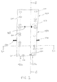
- Figure 1 shows a view looking down into a van 100 (the roof of the van 100 is, for convenience, transparent).
- the front of the van 100 has a cab 105 for the driver. Separated from the cab 105 by a bulkhead 108 is the rear 110 of the van 100.
- the rear 110 forms a cargo carrying portion of the van 100.
- Within the rear 110 are two wheel wells 115, one for each of the two rear wheels of the van 100.
- two doors 120 At the back of the van 100 are two doors 120 which provide access to the rear 110 of the van 100.
- a master rollerbed 150 is provided with rollerbed conveyors (not shown in Figure 1 ).
- Push/pull valves 155a, 155b are used by an operator to raise and lower the rollerbed conveyors.
- the master rollerbed 150 is joined to a slave rollerbed 160 (which has two separate sets of rollerbed conveyors, not shown in Figure 1 ) by couplers 165.
- the couplers 165 allow the master rollerbed 150 to be mechanically releasably coupled to the slave rollerbed 160.
- the couplers 165 are based on toggles though other arrangements such as screw threads and nuts may be used in other embodiments. It will also be appreciated that actuators differeing from the push/pull valves 155a, 155b could be used.
- the master rollerbed 150 is provided with releasable restraining pins 170.
- the restraining pins 170 are located near the wheel wells 115 (it is preferred that the master rollerbed 150 is provided with a variety of locations into which the pins 170 may be inserted so that, for a van 100 of a given size, the pins 170 can be located as near as practicable to the wheel wells 115).
- the pins 170 comprise a threaded shank that is screwed into the master 150; in this embodiment the master 170 is provided with a plurality of threaded holes (not shown) to receive the pins 170.
- the pins 170 may engage with some part of the van 100 other than the wheel wells 115. It will be appreciated that other mounting arrangements could be used to mount the rollerbed to the vehicle.
- the pins 170 provide a restraining mechanism for preventing excessive movement (for example during acceleration, braking or cornering of the van 100) of the master rollerbed 150 and slave rollerbed 160 relative to the van 100.
- the master rollerbed 150 and slave rollerbed 160 shouldnot move forwards relative to the van 100 or the slave rollerbed 160 will come into contact with the bulkhead 108.
- the master 10 and slave 160 ahould preferably not move backwards relative to the van 100 or the pins 170 will come into contact with the wheel wells 115.
- the pins 170 are shown in Figure 2 as being generally cylindrical, in other embodiments the pins may be of different size and shape.
- each pin 170 could be secured at two places to the master rollerbed 150; for convenience they are nonetheless referred to as pins.
- the master rollerbed 150 has a power lead 180 and a connector 185 that, in this embodiment, are used to electrically connect a compressor (discussed further in connection with Figure 7 ) to an accessory outlet such as a cigarette lighter within the cab 105. If necessary, a hole 190 may be drilled thought the bulkhead to allow the connector 185 to pass from the rear 110 of the van 100 to the cab 105.
- Figure 2 shows the master rollerbed 150 and the slave rollerbed 160 of Figure 1 , without the van 100. Also shown are roller apertures 200. Rollerbed conveyors (not shown in Figure 2 ; see Figures 3 and 4 ) can be raised so that they project through the roller apertures 200; each rollerbed conveyor is provided with a respective roller aperture 200.
- the embodiment of Figure 2 has one set of rollerbed conveyors on one side of the master rollerbed 150 and slave rollerbed 160, and another set of rollerbed conveyors on the other side. Alternative embodiments may have more or fewer sets, or may have different arrangements of rollers.
- master rollerbed 150 It is preferred to produce a master rollerbed 150 that is as long as reasonably possible while being short enough to fit into any van 100.
- the additional length (beyond that of the master rollerbed 150) that is available in larger vans 100 is accommodated by using one or more slave rollerbeds 160.
- master rollerbeds 160 may be produced in a range of bespoke sizes to fit each of the various types of vans 100.
- Figure 2 also shows non-return flaps 210.
- the non-return flaps 210 prevent inadvertent unloading of cargo from the van 100.
- the non-return flaps 210 are preferably resiliently sprung such that they are lowered into the rollerbed under downward pressure from a load resting on them and are resiliently biased so as to return to the raised position once the load has passed over them.
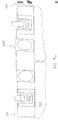
- Figures 3a and 3b show cross-sectional views of Figure 2 in the plane 3-3, with rollers in a lowered position; a portion of the cargo floor of the rear 110 of the van 100 is also shown.
- Figures 3a and 3b show a substantially flat panel 300; although the panel 300 is substantially flat, it may be embossed with dimples to increase the rigidity of the panel 300.
- the sides of the panel 300 are formed into "C" sections 310. These C sections 310 increase the longitudinal rigidity of the panel 300.
- the front and back ends of the panel 300 are also preferably formed into C sections (not visible in Figures 3a and 3b ).
- the panel 300 may be formed of mild steel. A portion of each C section forms a foot which suspends the panel off the floor of the vehicle 100.
- the height of the C sections 310, and thus the height of the panel 300 off the cargo floor of the van 100 is 54 mm. It is preferred that this height be as low as reasonably possible as the height otherwise reduces the volume in the rear 110 of the van 100 that is available for carrying cargo.
- top hat sections 320a - 320f (note that for convenience, Figures 3a and 3b show only the top hat sections 320a and 320f) are used to house six longitudinal air reservoirs 330a - 330f.
- each reservoir 330 is formed from a respective air sac.
- the reservoirs 330 are protected by the top hat sections 320, which may be formed of mild steel.
- the top hat sections 320 are joined (for example by welding or by using mechanical attachments such as bolts) to the panel 300 and further increase the longitudinal rigidity of the panel 300.
- the reservoirs may comprise rigid containers.
- roller channels 340a, 340b Attached underneath the panel 300 are two roller channels 340a, 340b, one at each side of the master rollerbed 150.
- the roller channels 340 further increases the longitudinal rigidity of the panel 300 of the master rollerbed 150.
- a respective air sac 350a, 350b Within each roller channel 340 is a respective air sac 350a, 350b.
- Above each air sac 350 is a respective roller carrier 360a, 360b.
- the roller carriers 360 support roller axles 365a, 365b which hold rollers 370.
- a single panel 300 reduces manufacturing costs as it not necessary to provide the master 150 with a floor - the C sections 310, together with the top hat sections 320 and the roller channels 340, rest on the cargo floor of the rear 110 of the van 100.
- the single panel 300 reduces the weight of the master rollerbed 150 - this maximises the cargo carrying capacity of the van 100 and also improves the ease by which the master rollerbed 150 and slave rollerbed 160 can be installed into a van 100; if the master 150 or slave 160 were too heavy then health and safety at work legislation would prevent a single operator from installing the master rollerbed 150 and/or the slave rollerbed 160. Instead, two people would be needed to install the master rollerbed 150 and/or slave rollerbed 160.
- the C sections 310 are preferred, some embodiments may omit the longitudinal C sections 310, and/or may omit the front and back C sections.
- the C sections 310 define an interior volume that can be regarded as underneath and/or within the flat panel 300; the top hat sections 320 and the roller channels 340 are located within the interior volume.
- the panel 300 is perforated by the roller apertures 200, with one aperture 200 for each roller 370.
- Figures 3a and 3b show the rollers 370 when retracted beneath the roller apertures 200, i.e. when the air sacs 350 are not inflated.
- Figures 4a and 4b show the same view as Figures 3a and 3b , respectively, but with the rollers 370 in a raised position, i.e. when the air sacs 350 are inflated.
- the reservoirs 330 are arranged to hold air at a pressure of approximately 2 bar (30 pounds per square inch) and are preferably sized so as to store a sufficient volume of pressurised air to inflate the air sacs 350 on three separate occasions.
- a compressor see Figure 7 for details of the compressor
- the air sacs 350 can be inflated.
- Figures 3a , 3b and 4a and 4b show cross-sectional views of the master rollerbed 150.
- the cross section of the slave rollerbed 160 (not shown) is similar to that of the master rollerbed 150.
- Figure 5 shows a partial cross-sectional view of Figure 2 in the lane 5-5.
- the push/pull valves 155 are located at the back of the master rollerbed 150.
- the push/pull valves are shown in Figure 5 in a pulled out configuration, this causes the rollers 370 to be raised.
- the rollers 370 are lowered below the apertures 200.
- rollers 370 lowered, when the push/pull valves 155 are pushed in, is that the doors 120 of the van 100 can be arranged to bear against the push/pull valves 155 (and thus retract the rollers 370) in the event that an operator forgets to push in the push/pull valves 155 before closing the doors 120. This is illustrated in more detail in Figures 8b and 8c .
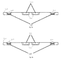
- Figures 6a , 6b and 6c shows the same view as Figure 5 but with a pallet 600.
- FIG 6a only a portion of the pallet is shown.
- the pallet 600 is shown as it is being loaded into the van 100.
- the rear of the pallet 600 is shown about to clear the non-return flaps 210.
- the weight of the pallet 600 pushes down the flaps 210.
- inadvertent unloading of the pallet 600 e.g.
- the pallet 600 sliding backwards out of the van 100 is prevented as the tops of the flaps 210 are higher (by a height denoted as "h") than the tops of the rollers 370 and thus the rear of the pallet 600 would come to rest against the flaps 210.
- the flaps 210 are spring loaded though in alternative embodiments, weights may be used to bias the flaps 210 into position. In other embodiments, one or more flaps 210 may be used instead of two flaps 210.
- the non-return flaps 210 are only required when the rollers 370 have been raised. This is because when the rollers 370 have been lowered, the pallet 600 would be resting directly on the flat panel 300; it would, due to friction, be difficult to slide the pallet 600 off the flat panel 300.
- the flaps 210 are arranged to be recessed (i.e. below the surface of the flat panel 300) when the rollers 370 are lowered; when the rollers 370 are raised, the flaps 210 are urged, for example by a resilient device such as a spring, to project above the flat panel 300 and above the rollers 370.
- the pallet's weight urges the flap 210 into the body of the panel.
- the flap 210 is resiliently baised towards a deployed position by a sprung lever 211, although other resilient sprung mechanisms such as springs, materials with elastic properties etc could be used.
- Figure 7 shows a schematic diagram of a pneumatic system comprising a compressor 700 controlled by an electrical on/off switch 705.
- the on/off switch is located towards the rear of the master rollerbed 150 so that it is readily accessible by an operator.
- the compressor 700 is regulated so that it inflates the reservoirs 330a - 330f to 2 bar.
- the pneumatic coupling 711 connects the reservoirs 330 to reservoirs 730a - 730f in the slave rollerbed 160.
- the pneumatic coupling 712a connects the air sac 750a to the air sac 350a.
- the pneumatic coupling 712b connects the air sac 750b to the air sac 350b.
- a gauge 760 allows an operator to monitor the pressure within the reservoirs 330, 730.
- the gauge is not essential but is preferred to allow an operator to assess how much air remains within the reservoirs, and whether the compressor 700 needs to be switched on.
- the push/pull valves 155a, 155b are three port, two position, valves. When in their pulled out position, the valves 155 connect the reservoirs 330, 730 to the air sacs 350 (and air sacs 750a, 750b in the slave rollerbed 160, via the pneumatic couplings 712a, 712b) to inflate the air sacs 350, 750 and raise the rollers 370. When pushed in, the valves 155 connect the air sacs 350, 750 to the atmosphere to allow the air inside the air sacs 350, 370 to be discharged, and to lower the rollers 370. In other embodiments, a single valve may be used instead of the pair of valves 155a, 155b. Also, in other embodiments the valve(s) need not be push/pull valves. For example, electrical switches could be used to control solenoid operated valves.
- the reservoirs could instead be recharged by a compressed air cylinder or the like that could be connected via a one way valve, discharged into the reservoirs and then disconnected.
- a C section 310 may be formed along only one side of the master rollerbed 150 or the slave rollerbed 160, though it is preferred that a C section 310 be formed along both sides.
- a C section may, in addition to or instead of C sections at the sides, be formed at one or at both ends of the master rollerbed 150 or the slave rollerbed 160.
- the rollerbeds 150, 160 will be rectangular and are provided with four C sections.
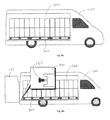
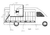
- FIG 8a illustrates a fully loaded vehicle incorporating an embodiment of the present invention.
- Figures 8b and 8c show the vehicle during the loading process.
- the exploded area 800 shows the action of the vehicle door 120 against the push/pull valve 155.
- the push/pull valve can be in its pulled state (meaning the rollers 370 are lifted and the contents can be slid back and forth inside the van 100 freely).
- the door 120 is closed, as shown in Figure 8c , the door 120 of the van 100 bears against the push/pull valve 155, causing it to move to the pushed state and thus retract the rollers 370.
- the contents can no longer move back and forth freely in the vehicle.
Landscapes
- Engineering & Computer Science (AREA)
- Mechanical Engineering (AREA)
- Aviation & Aerospace Engineering (AREA)
- Rollers For Roller Conveyors For Transfer (AREA)
- Footwear And Its Accessory, Manufacturing Method And Apparatuses (AREA)
- Rolls And Other Rotary Bodies (AREA)
- Body Structure For Vehicles (AREA)
Abstract
Description
- The present invention relates to rollerbeds (which are also known as rollerbed conveyors). In particular the present invention relates to a rollerbed suitable for retrofitting into vehicles such as vans.
- Rollerbeds are known for material handling in vehicles such as lorries or aircraft. Such rollerbeds are installed into the vehicle during the manufacture of the vehicle.
-
GB 2378692 FR-A-2565 565 - According to an aspect of the present invention, there is provided a rollerbed as claimed in
claim 1. A method for fitting a rollerbed to a vehicle is another aspect of the present invention as claimed in claim 15. - The present invention seeks to provide a rollerbed that can be readily and easily installed into a vehicle such as a van after manufacture of the vehicle. Vans are typically sold with a flat cargo bay and it would be desirable to be able to conveniently retrofit a rollerbed to a van, thereby improving the ease by which goods such as pallets can be loaded into, and out of, the van. Preferably, the rollerbed conveyors are non-powered.
- The rollerbed of embodiments of the present invention has the advantage that the flat panel provides a surface for supporting pallets, without requiring a lower floor. The C sections increase the rigidity of the flat panel. The rollerbed conveyors are attached to the panel and further increase the rigidity of the flat panel.
- A preferred embodiment further comprises pneumatic reservoirs located within "top-hat" sections.
- Embodiments of the present invention will now be described in detail, by way of example only, with reference to the accompanying drawings in which:
-
Figure 1 shows a view looking down into a van incorporating an embodiment of the present invention (the roof of the van is, for convenience, transparent). -
Figure 2 shows a master rollerbed and a slave rollerbed ofFigure 1 . -
Figures 3a and3b show cross-sectional views ofFigure 2 in the plane 3-3, with rollers in a lowered position. -
Figures 4a and4b show the same views asFigures 3a and3b but with the rollers in a raised position. -
Figure 5 shows a partial cross-sectional view ofFigure 2 in the plane 5-5. -
Figure 6a ,6b and 6c show the same view asFigure 5 but with a pallet. -
Figure 7 shows a schematic diagram of a pneumatic system. -
Figure 8a illustrates a fully loaded vehicle incorporating an embodiment of the present invention.Figures 8b and8c show the vehicle during the loading process. -
Figure 1 shows a view looking down into a van 100 (the roof of thevan 100 is, for convenience, transparent). The front of thevan 100 has acab 105 for the driver. Separated from thecab 105 by abulkhead 108 is the rear 110 of thevan 100. The rear 110 forms a cargo carrying portion of thevan 100. Within the rear 110 are twowheel wells 115, one for each of the two rear wheels of thevan 100. At the back of thevan 100 are twodoors 120 which provide access to the rear 110 of thevan 100. - A
master rollerbed 150 according to an embodiment of the present invention is provided with rollerbed conveyors (not shown inFigure 1 ). Push/pull valves master rollerbed 150 is joined to a slave rollerbed 160 (which has two separate sets of rollerbed conveyors, not shown inFigure 1 ) bycouplers 165. Thecouplers 165 allow themaster rollerbed 150 to be mechanically releasably coupled to theslave rollerbed 160. In this embodiment thecouplers 165 are based on toggles though other arrangements such as screw threads and nuts may be used in other embodiments. It will also be appreciated that actuators differeing from the push/pull valves - The
master rollerbed 150 is provided withreleasable restraining pins 170. In the illustrated embodiment, therestraining pins 170 are located near the wheel wells 115 (it is preferred that themaster rollerbed 150 is provided with a variety of locations into which thepins 170 may be inserted so that, for avan 100 of a given size, thepins 170 can be located as near as practicable to the wheel wells 115). In this embodiment thepins 170 comprise a threaded shank that is screwed into themaster 150; in this embodiment themaster 170 is provided with a plurality of threaded holes (not shown) to receive thepins 170. In other embodiments, thepins 170 may engage with some part of thevan 100 other than thewheel wells 115. It will be appreciated that other mounting arrangements could be used to mount the rollerbed to the vehicle. - The
pins 170 provide a restraining mechanism for preventing excessive movement (for example during acceleration, braking or cornering of the van 100) of themaster rollerbed 150 andslave rollerbed 160 relative to thevan 100. Preferably, themaster rollerbed 150 andslave rollerbed 160 shouldnot move forwards relative to thevan 100 or theslave rollerbed 160 will come into contact with thebulkhead 108. Similarly, themaster 10 andslave 160 ahould preferably not move backwards relative to thevan 100 or thepins 170 will come into contact with thewheel wells 115. Although thepins 170 are shown inFigure 2 as being generally cylindrical, in other embodiments the pins may be of different size and shape. For example, eachpin 170 could be secured at two places to themaster rollerbed 150; for convenience they are nonetheless referred to as pins. - Sideways movement of the
master rollerbed 150 andslave rollerbed 160 relative to thevan 100 is prevented by making the width of themaster rollerbed 150 andslave rollerbed 160 only a little less than the spacing between thewheel wells 115. Most light duty vans have a spacing between their rear wheel wells of 1300 mm and in this embodiment the width of themaster rollerbed 150, and of theslave rollerbed 160, is 1260 mm. Alternatively, additional mounting pins or other devices could be used to restrain the rollerbed. - The
master rollerbed 150 has apower lead 180 and aconnector 185 that, in this embodiment, are used to electrically connect a compressor (discussed further in connection withFigure 7 ) to an accessory outlet such as a cigarette lighter within thecab 105. If necessary, ahole 190 may be drilled thought the bulkhead to allow theconnector 185 to pass from the rear 110 of thevan 100 to thecab 105. -
Figure 2 shows themaster rollerbed 150 and theslave rollerbed 160 ofFigure 1 , without thevan 100. Also shown areroller apertures 200. Rollerbed conveyors (not shown inFigure 2 ; seeFigures 3 and4 ) can be raised so that they project through theroller apertures 200; each rollerbed conveyor is provided with arespective roller aperture 200. The embodiment ofFigure 2 has one set of rollerbed conveyors on one side of themaster rollerbed 150 andslave rollerbed 160, and another set of rollerbed conveyors on the other side. Alternative embodiments may have more or fewer sets, or may have different arrangements of rollers. - It is preferred to produce a
master rollerbed 150 that is as long as reasonably possible while being short enough to fit into anyvan 100. The additional length (beyond that of the master rollerbed 150) that is available inlarger vans 100 is accommodated by using one ormore slave rollerbeds 160. Alternatively, master rollerbeds 160 may be produced in a range of bespoke sizes to fit each of the various types ofvans 100. -
Figure 2 also showsnon-return flaps 210. As will be discussed in more detail in connection withFigures 5 and6 , thenon-return flaps 210 prevent inadvertent unloading of cargo from thevan 100. Thenon-return flaps 210 are preferably resiliently sprung such that they are lowered into the rollerbed under downward pressure from a load resting on them and are resiliently biased so as to return to the raised position once the load has passed over them. -
Figures 3a and3b show cross-sectional views ofFigure 2 in the plane 3-3, with rollers in a lowered position; a portion of the cargo floor of the rear 110 of thevan 100 is also shown.Figures 3a and3b show a substantiallyflat panel 300; although thepanel 300 is substantially flat, it may be embossed with dimples to increase the rigidity of thepanel 300. The sides of thepanel 300 are formed into "C"sections 310. TheseC sections 310 increase the longitudinal rigidity of thepanel 300. The front and back ends of thepanel 300 are also preferably formed into C sections (not visible inFigures 3a and3b ). Thepanel 300 may be formed of mild steel. A portion of each C section forms a foot which suspends the panel off the floor of thevehicle 100. - In this embodiment, the height of the
C sections 310, and thus the height of thepanel 300 off the cargo floor of thevan 100, is 54 mm. It is preferred that this height be as low as reasonably possible as the height otherwise reduces the volume in the rear 110 of thevan 100 that is available for carrying cargo. - Six "top hat" sections 320a - 320f (note that for convenience,
Figures 3a and3b show only thetop hat sections 320a and 320f) are used to house six longitudinal air reservoirs 330a - 330f. In this embodiment eachreservoir 330 is formed from a respective air sac. Thereservoirs 330 are protected by the top hat sections 320, which may be formed of mild steel. The top hat sections 320 are joined (for example by welding or by using mechanical attachments such as bolts) to thepanel 300 and further increase the longitudinal rigidity of thepanel 300. In this embodiment there are six top hat sections 320 and sixreservoirs 330; there may be fewer or more in other embodiments. In alternative embodiments, the reservoirs may comprise rigid containers. - Attached underneath the
panel 300 are two roller channels 340a, 340b, one at each side of themaster rollerbed 150. Theroller channels 340 further increases the longitudinal rigidity of thepanel 300 of themaster rollerbed 150. Within eachroller channel 340 is arespective air sac 350a, 350b. Above eachair sac 350 is a respective roller carrier 360a, 360b. The roller carriers 360 support roller axles 365a, 365b which holdrollers 370. - The use of a
single panel 300 reduces manufacturing costs as it not necessary to provide themaster 150 with a floor - theC sections 310, together with the top hat sections 320 and theroller channels 340, rest on the cargo floor of the rear 110 of thevan 100. As well as reducing manufacturing costs, thesingle panel 300 reduces the weight of the master rollerbed 150 - this maximises the cargo carrying capacity of thevan 100 and also improves the ease by which the master rollerbed 150 and slave rollerbed 160 can be installed into avan 100; if themaster 150 orslave 160 were too heavy then health and safety at work legislation would prevent a single operator from installing the master rollerbed 150 and/or theslave rollerbed 160. Instead, two people would be needed to install the master rollerbed 150 and/orslave rollerbed 160. - Although the
C sections 310 are preferred, some embodiments may omit thelongitudinal C sections 310, and/or may omit the front and back C sections. In effect, theC sections 310 define an interior volume that can be regarded as underneath and/or within theflat panel 300; the top hat sections 320 and theroller channels 340 are located within the interior volume. - The
panel 300 is perforated by theroller apertures 200, with oneaperture 200 for eachroller 370. -
Figures 3a and3b show therollers 370 when retracted beneath theroller apertures 200, i.e. when theair sacs 350 are not inflated. -
Figures 4a and4b show the same view asFigures 3a and3b , respectively, but with therollers 370 in a raised position, i.e. when theair sacs 350 are inflated. In this embodiment, thereservoirs 330 are arranged to hold air at a pressure of approximately 2 bar (30 pounds per square inch) and are preferably sized so as to store a sufficient volume of pressurised air to inflate theair sacs 350 on three separate occasions. Thus even when a compressor (seeFigure 7 for details of the compressor) has been switched off and is no longer providing compressed air to replenish thereservoirs 330, theair sacs 350 can be inflated. -
Figures 3a ,3b and4a and4b show cross-sectional views of themaster rollerbed 150. In this embodiment of the invention, the cross section of the slave rollerbed 160 (not shown) is similar to that of themaster rollerbed 150. -
Figure 5 shows a partial cross-sectional view ofFigure 2 in the lane 5-5. As shown, the push/pull valves 155 are located at the back of themaster rollerbed 150. The push/pull valves are shown inFigure 5 in a pulled out configuration, this causes therollers 370 to be raised. When the push/pull valves 155 are pushed in (shown in phantom lines), therollers 370 are lowered below theapertures 200. An advantage of having therollers 370 lowered, when the push/pull valves 155 are pushed in, is that thedoors 120 of thevan 100 can be arranged to bear against the push/pull valves 155 (and thus retract the rollers 370) in the event that an operator forgets to push in the push/pull valves 155 before closing thedoors 120. This is illustrated in more detail inFigures 8b and8c . -
Figures 6a ,6b and 6c shows the same view asFigure 5 but with apallet 600. Infigure 6a , only a portion of the pallet is shown. Thepallet 600 is shown as it is being loaded into thevan 100. The rear of thepallet 600 is shown about to clear the non-return flaps 210. As can be seen by comparing theflaps 210 inFigure 6a withFigure 5 , inFigure 6a the weight of thepallet 600 pushes down theflaps 210. Once thepallet 600 has cleared theflaps 210, inadvertent unloading of the pallet 600 (e.g. thepallet 600 sliding backwards out of the van 100) is prevented as the tops of theflaps 210 are higher (by a height denoted as "h") than the tops of therollers 370 and thus the rear of thepallet 600 would come to rest against theflaps 210. In this embodiment theflaps 210 are spring loaded though in alternative embodiments, weights may be used to bias theflaps 210 into position. In other embodiments, one ormore flaps 210 may be used instead of twoflaps 210. - Strictly speaking, the
non-return flaps 210 are only required when therollers 370 have been raised. This is because when therollers 370 have been lowered, thepallet 600 would be resting directly on theflat panel 300; it would, due to friction, be difficult to slide thepallet 600 off theflat panel 300. In some embodiments, theflaps 210 are arranged to be recessed (i.e. below the surface of the flat panel 300) when therollers 370 are lowered; when therollers 370 are raised, theflaps 210 are urged, for example by a resilient device such as a spring, to project above theflat panel 300 and above therollers 370. - As can be seen in
Figures 6b and 6c , the pallet's weight urges theflap 210 into the body of the panel. Theflap 210 is resiliently baised towards a deployed position by a sprung lever 211, although other resilient sprung mechanisms such as springs, materials with elastic properties etc could be used. -
Figure 7 shows a schematic diagram of a pneumatic system comprising a compressor 700 controlled by an electrical on/off switch 705. For convenience, the on/off switch is located towards the rear of the master rollerbed 150 so that it is readily accessible by an operator. In this embodiment the compressor 700 is regulated so that it inflates the reservoirs 330a - 330f to 2 bar. - As can be seen, as well as the
mechanical couplers 165 between the master rollerbed 150 and slave rollerbed 160, there are (in this embodiment) threepneumatic couplings 711, 712a, 712b. Thepneumatic coupling 711 connects thereservoirs 330 to reservoirs 730a - 730f in theslave rollerbed 160. The pneumatic coupling 712a connects the air sac 750a to the air sac 350a. The pneumatic coupling 712b connects the air sac 750b to theair sac 350b. - A
gauge 760 allows an operator to monitor the pressure within thereservoirs 330, 730. The gauge is not essential but is preferred to allow an operator to assess how much air remains within the reservoirs, and whether the compressor 700 needs to be switched on. - The push/
pull valves valves 155 connect thereservoirs 330, 730 to the air sacs 350 (and air sacs 750a, 750b in the slave rollerbed 160, via the pneumatic couplings 712a, 712b) to inflate theair sacs 350, 750 and raise therollers 370. When pushed in, thevalves 155 connect theair sacs 350, 750 to the atmosphere to allow the air inside theair sacs rollers 370. In other embodiments, a single valve may be used instead of the pair ofvalves - Although the use of compressed air, together with air sacs, is preferred to raise and lower the
rollers 370, in alternative embodiments other arrangements, such as a scissor-type lifting mechanism, may be used instead. It will be appreciated that instead of a compressor, the reservoirs could instead be recharged by a compressed air cylinder or the like that could be connected via a one way valve, discharged into the reservoirs and then disconnected. - In some embodiments, a
C section 310 may be formed along only one side of the master rollerbed 150 or the slave rollerbed 160, though it is preferred that aC section 310 be formed along both sides. In other embodiments, a C section may, in addition to or instead of C sections at the sides, be formed at one or at both ends of the master rollerbed 150 or theslave rollerbed 160. In most embodiments therollerbeds -
Figure 8a illustrates a fully loaded vehicle incorporating an embodiment of the present invention.Figures 8b and8c show the vehicle during the loading process. The exploded area 800 shows the action of thevehicle door 120 against the push/pull valve 155. As can be seen inFigure 8b , when thedoor 120 is open, the push/pull valve can be in its pulled state (meaning therollers 370 are lifted and the contents can be slid back and forth inside thevan 100 freely). When thedoor 120 is closed, as shown inFigure 8c , thedoor 120 of thevan 100 bears against the push/pull valve 155, causing it to move to the pushed state and thus retract therollers 370. The contents can no longer move back and forth freely in the vehicle.
Claims (15)
- A rollerbed for a cargo area of a vehicle comprising:a single substantially flat panel (300) and "C" sections (310) formed along one or more sides, wherein a plurality of apertures (200) are defined in the substantially flat panel; anda plurality of rollers (150, 160) movable between a lowered position and a raised position, wherein in the raised position the rollers project through the apertures, and wherein in the lowered position the rollers do not project through the apertures;wherein the width of the panel extends substantially across the spacing between the wheel wells (115) of the cargo area of the vehicle (100), the panel including restraining means (170) for restraining movement of the panel when mounted within the cargo area of the vehicle.
- A rollerbed according to claim 1, wherein each "C" section has a height perpendicular to the plane of the substantially flat panel that is greater than or equal to the diameter of the rollers, each "C" section further comprises a foot whereby when the rollerbed is placed on a surface, the foot of the "C" section suspends the substantially flat panel and the plurality of rollers in the lowered position above the surface.
- A rollerbed according to claim 1 or 2, further comprising:one or more roller channels (340, 340a), wherein the one or more roller channels are secured to the substantially flat panel such that rigidity of the substantially flat panel is increased.
- A rollerbed according to claim 1, 2 or 3, comprising:one or more gas sacs (350, 350a) coupled to one or more gas reservoirs (330a - 330f), wherein the one or more sacs are inflatable via gas from the gas reservoirs to move the rollers between the lowered position and the raised position.
- A rollerbed according to any preceding claim, comprising:one or more top hat sections (320a - 320f), wherein the one or more top hat sections are secured to the substantially flat panel such that the rigidity of the substantially flat panel is increased.
- A rollerbed according to claim 5 when dependent on claim 4, wherein the one or more reservoirs are housed in the one or more top hat sections.
- A rollerbed according to claim 4, 5 or 6, further comprising:a compressor (700) arranged to charge the one or more gas reservoirs.
- A rollerbed according to any preceding claim, comprising:one or more non-return flaps (210), wherein the one or more non-return flaps are urged, at least when the rollers are in the raised position, above the rollers so as impede the unloading of goods (600).
- A rollerbed according to any preceding claim, wherein the restraining means comprises one or more pins.
- A rollerbed according to any preceding claim, comprising:a control device, such as a push/pull valve (155a, 155b), for selecting a lowered or a raised position for the rollers.
- A rollerbed according to claim 10, wherein the control device is arranged for interaction with a vehicle door (120), such that when the vehicle door is closed then the rollers are lowered.
- A rollerbed according to any preceding claim, wherein the rollerbed is a master rollerbed (150), comprising:one or more mechanical couplers (165) for attaching the master rollerbed to a slave rollerbed (160).
- A rollerbed according to any preceding claim, wherein the rollerbed is a master rollerbed, comprising:one or more electrical and/or pneumatic couplers (711, 712a, 712b) for connecting the master rollerbed to a slave rollerbed such that rollers of the slave rollerbed imitate rollers of the master rollerbed.
- A rollerbed according to any preceding claim, having either two or four "C" sections.
- A method of fitting a rollerbed to a vehicle (100), comprising the steps of:providing a rollerbed comprising: a single substantially flat panel (300) having "C" sections (310) formed along one or more sides, wherein a plurality of apertures (200) are defined in the substantially flat panel; and a plurality of rollers (150, 160) movable between a lowered position and a raised position, wherein in the raised position the rollers project through the apertures, and wherein in the lowered position the rollers do not project through the apertures; wherein the width of the panel extends substantially across the spacing between the wheel wells (115) of the cargo area of the vehicle (100);providing pins (170);fitting the pins to the rollerbed such that the rollerbed is restrained in the vehicle.
Applications Claiming Priority (1)
| Application Number | Priority Date | Filing Date | Title |
|---|---|---|---|
| GB0817139A GB2463661A (en) | 2008-09-18 | 2008-09-18 | Roller Bed |
Publications (4)
| Publication Number | Publication Date |
|---|---|
| EP2165947A2 EP2165947A2 (en) | 2010-03-24 |
| EP2165947A3 EP2165947A3 (en) | 2010-03-31 |
| EP2165947B1 true EP2165947B1 (en) | 2012-02-22 |
| EP2165947B8 EP2165947B8 (en) | 2012-08-08 |
Family
ID=39951835
Family Applications (1)
| Application Number | Title | Priority Date | Filing Date |
|---|---|---|---|
| EP09275083A Active EP2165947B8 (en) | 2008-09-18 | 2009-09-18 | Rollerbed |
Country Status (3)
| Country | Link |
|---|---|
| EP (1) | EP2165947B8 (en) |
| AT (1) | ATE546390T1 (en) |
| GB (1) | GB2463661A (en) |
Families Citing this family (1)
| Publication number | Priority date | Publication date | Assignee | Title |
|---|---|---|---|---|
| CH714714A1 (en) * | 2018-03-02 | 2019-09-13 | Ferag Ag | Device for transporting transport goods. |
Family Cites Families (8)
| Publication number | Priority date | Publication date | Assignee | Title |
|---|---|---|---|---|
| EP0002106A1 (en) * | 1977-10-14 | 1979-05-30 | Hydraroll Limited | Load handling apparatus with liftable rollers, and floor equipped therewith |
| AU555408B2 (en) * | 1981-08-27 | 1986-09-25 | Hydraroll Ltd. | Roller conveyor handling apparatus |
| DE3421345A1 (en) * | 1984-06-08 | 1985-12-12 | Messerschmitt-Bölkow-Blohm GmbH, 2800 Bremen | Ball-supported mat for receiving and displacing loads |
| US4930612A (en) * | 1988-11-22 | 1990-06-05 | Atlantis Transportation Services Inc. | Roller track assembly incorporating a mechanical elevator mechanism |
| US6193043B1 (en) * | 1999-05-17 | 2001-02-27 | Ancra International Llc | Retractable roller system for handling cargo |
| US6422372B2 (en) * | 2000-02-28 | 2002-07-23 | Morgan Corporation | Roller conveying apparatus |
| US6554116B2 (en) * | 2000-09-01 | 2003-04-29 | Morgan Corporation | Quick release roller track top plate |
| GB0117763D0 (en) | 2001-07-20 | 2001-09-12 | Transpotech Ltd | Mechanical handling apparatus |
-
2008
- 2008-09-18 GB GB0817139A patent/GB2463661A/en not_active Withdrawn
-
2009
- 2009-09-18 AT AT09275083T patent/ATE546390T1/en active
- 2009-09-18 EP EP09275083A patent/EP2165947B8/en active Active
Also Published As
| Publication number | Publication date |
|---|---|
| ATE546390T1 (en) | 2012-03-15 |
| EP2165947A3 (en) | 2010-03-31 |
| GB0817139D0 (en) | 2008-10-29 |
| GB2463661A (en) | 2010-03-24 |
| EP2165947A2 (en) | 2010-03-24 |
| EP2165947B8 (en) | 2012-08-08 |
Similar Documents
| Publication | Publication Date | Title |
|---|---|---|
| US10611287B2 (en) | Air bag system for lifting trailer platforms | |
| US5765859A (en) | Modular squatdown wheeled suspension system | |
| US9108557B2 (en) | Low center of gravity carrier | |
| US20230398920A1 (en) | Vehicle Cargo Container and Lift Frame Assembly with Inflatable Bag-Assisted Lift Frame for Vehicle | |
| EP3204259B1 (en) | Pneumatic platform tow truck with hinge | |
| US6158556A (en) | Vehicle safety mechanism for dissipating collision forces | |
| WO2009079181A1 (en) | Semi trailer dolly | |
| US8376683B2 (en) | Low center of gravity carrier | |
| CA3085028A1 (en) | Lift frame assembly for vehicle with air suspension, cargo container assembly, lift frame and cargo container assembly, and methods of using same | |
| AU2015101572A4 (en) | Auto lift trailer | |
| JP5318794B2 (en) | Trailer axle lifting device | |
| EP2165947A2 (en) | Rollerbed | |
| MX2008000674A (en) | Locking mechanism for movable subframe of tractor-trailers. | |
| EP1813497A1 (en) | System for the combined transportation of goods by rail and road | |
| KR100831700B1 (en) | Heavy weight moving device | |
| US7441781B2 (en) | Lift system for raising the rear of a truck | |
| CN110901606A (en) | Belt-shaped auxiliary brake device | |
| CA3056512A1 (en) | Inflatable bag-assisted lift frame for vehicle | |
| CN218463519U (en) | Self-unloading semitrailer with limiting mechanism | |
| CA3152596C (en) | A lift system for elevating a load bed of a vehicle | |
| US20010022432A1 (en) | Adjustable suspension system | |
| IE20000970A1 (en) | Semi-Trailer Assembly | |
| GB2319504A (en) | Road trailers | |
| GB2337731A (en) | Trailer Assembly | |
| WO2003013885A1 (en) | Adjustable suspension system |
Legal Events
| Date | Code | Title | Description |
|---|---|---|---|
| PUAI | Public reference made under article 153(3) epc to a published international application that has entered the european phase |
Free format text: ORIGINAL CODE: 0009012 |
|
| PUAL | Search report despatched |
Free format text: ORIGINAL CODE: 0009013 |
|
| AK | Designated contracting states |
Kind code of ref document: A2 Designated state(s): AT BE BG CH CY CZ DE DK EE ES FI FR GB GR HR HU IE IS IT LI LT LU LV MC MK MT NL NO PL PT RO SE SI SK SM TR |
|
| AK | Designated contracting states |
Kind code of ref document: A3 Designated state(s): AT BE BG CH CY CZ DE DK EE ES FI FR GB GR HR HU IE IS IT LI LT LU LV MC MK MT NL NO PL PT RO SE SI SK SM TR |
|
| 17P | Request for examination filed |
Effective date: 20100929 |
|
| RIC1 | Information provided on ipc code assigned before grant |
Ipc: B65G 13/12 20060101AFI20110719BHEP Ipc: B65G 67/20 20060101ALI20110719BHEP |
|
| GRAP | Despatch of communication of intention to grant a patent |
Free format text: ORIGINAL CODE: EPIDOSNIGR1 |
|
| GRAS | Grant fee paid |
Free format text: ORIGINAL CODE: EPIDOSNIGR3 |
|
| GRAA | (expected) grant |
Free format text: ORIGINAL CODE: 0009210 |
|
| AK | Designated contracting states |
Kind code of ref document: B1 Designated state(s): AT BE BG CH CY CZ DE DK EE ES FI FR GB GR HR HU IE IS IT LI LT LU LV MC MK MT NL NO PL PT RO SE SI SK SM TR |
|
| REG | Reference to a national code |
Ref country code: GB Ref legal event code: FG4D |
|
| REG | Reference to a national code |
Ref country code: CH Ref legal event code: EP |
|
| REG | Reference to a national code |
Ref country code: AT Ref legal event code: REF Ref document number: 546390 Country of ref document: AT Kind code of ref document: T Effective date: 20120315 |
|
| REG | Reference to a national code |
Ref country code: IE Ref legal event code: FG4D |
|
| REG | Reference to a national code |
Ref country code: DE Ref legal event code: R096 Ref document number: 602009005462 Country of ref document: DE Effective date: 20120412 |
|
| REG | Reference to a national code |
Ref country code: NL Ref legal event code: T3 |
|
| RAP2 | Party data changed (patent owner data changed or rights of a patent transferred) |
Owner name: JOLODA (INTERNATIONAL) LIMITED |
|
| LTIE | Lt: invalidation of european patent or patent extension |
Effective date: 20120222 |
|
| PG25 | Lapsed in a contracting state [announced via postgrant information from national office to epo] |
Ref country code: IS Free format text: LAPSE BECAUSE OF FAILURE TO SUBMIT A TRANSLATION OF THE DESCRIPTION OR TO PAY THE FEE WITHIN THE PRESCRIBED TIME-LIMIT Effective date: 20120622 Ref country code: HR Free format text: LAPSE BECAUSE OF FAILURE TO SUBMIT A TRANSLATION OF THE DESCRIPTION OR TO PAY THE FEE WITHIN THE PRESCRIBED TIME-LIMIT Effective date: 20120222 Ref country code: LT Free format text: LAPSE BECAUSE OF FAILURE TO SUBMIT A TRANSLATION OF THE DESCRIPTION OR TO PAY THE FEE WITHIN THE PRESCRIBED TIME-LIMIT Effective date: 20120222 Ref country code: NO Free format text: LAPSE BECAUSE OF FAILURE TO SUBMIT A TRANSLATION OF THE DESCRIPTION OR TO PAY THE FEE WITHIN THE PRESCRIBED TIME-LIMIT Effective date: 20120522 |
|
| PG25 | Lapsed in a contracting state [announced via postgrant information from national office to epo] |
Ref country code: PT Free format text: LAPSE BECAUSE OF FAILURE TO SUBMIT A TRANSLATION OF THE DESCRIPTION OR TO PAY THE FEE WITHIN THE PRESCRIBED TIME-LIMIT Effective date: 20120622 Ref country code: FI Free format text: LAPSE BECAUSE OF FAILURE TO SUBMIT A TRANSLATION OF THE DESCRIPTION OR TO PAY THE FEE WITHIN THE PRESCRIBED TIME-LIMIT Effective date: 20120222 Ref country code: LV Free format text: LAPSE BECAUSE OF FAILURE TO SUBMIT A TRANSLATION OF THE DESCRIPTION OR TO PAY THE FEE WITHIN THE PRESCRIBED TIME-LIMIT Effective date: 20120222 Ref country code: GR Free format text: LAPSE BECAUSE OF FAILURE TO SUBMIT A TRANSLATION OF THE DESCRIPTION OR TO PAY THE FEE WITHIN THE PRESCRIBED TIME-LIMIT Effective date: 20120523 |
|
| REG | Reference to a national code |
Ref country code: AT Ref legal event code: MK05 Ref document number: 546390 Country of ref document: AT Kind code of ref document: T Effective date: 20120222 |
|
| PG25 | Lapsed in a contracting state [announced via postgrant information from national office to epo] |
Ref country code: CY Free format text: LAPSE BECAUSE OF FAILURE TO SUBMIT A TRANSLATION OF THE DESCRIPTION OR TO PAY THE FEE WITHIN THE PRESCRIBED TIME-LIMIT Effective date: 20120222 |
|
| PG25 | Lapsed in a contracting state [announced via postgrant information from national office to epo] |
Ref country code: CZ Free format text: LAPSE BECAUSE OF FAILURE TO SUBMIT A TRANSLATION OF THE DESCRIPTION OR TO PAY THE FEE WITHIN THE PRESCRIBED TIME-LIMIT Effective date: 20120222 Ref country code: EE Free format text: LAPSE BECAUSE OF FAILURE TO SUBMIT A TRANSLATION OF THE DESCRIPTION OR TO PAY THE FEE WITHIN THE PRESCRIBED TIME-LIMIT Effective date: 20120222 Ref country code: SI Free format text: LAPSE BECAUSE OF FAILURE TO SUBMIT A TRANSLATION OF THE DESCRIPTION OR TO PAY THE FEE WITHIN THE PRESCRIBED TIME-LIMIT Effective date: 20120222 Ref country code: PL Free format text: LAPSE BECAUSE OF FAILURE TO SUBMIT A TRANSLATION OF THE DESCRIPTION OR TO PAY THE FEE WITHIN THE PRESCRIBED TIME-LIMIT Effective date: 20120222 Ref country code: DK Free format text: LAPSE BECAUSE OF FAILURE TO SUBMIT A TRANSLATION OF THE DESCRIPTION OR TO PAY THE FEE WITHIN THE PRESCRIBED TIME-LIMIT Effective date: 20120222 Ref country code: SE Free format text: LAPSE BECAUSE OF FAILURE TO SUBMIT A TRANSLATION OF THE DESCRIPTION OR TO PAY THE FEE WITHIN THE PRESCRIBED TIME-LIMIT Effective date: 20120222 Ref country code: RO Free format text: LAPSE BECAUSE OF FAILURE TO SUBMIT A TRANSLATION OF THE DESCRIPTION OR TO PAY THE FEE WITHIN THE PRESCRIBED TIME-LIMIT Effective date: 20120222 |
|
| PG25 | Lapsed in a contracting state [announced via postgrant information from national office to epo] |
Ref country code: SK Free format text: LAPSE BECAUSE OF FAILURE TO SUBMIT A TRANSLATION OF THE DESCRIPTION OR TO PAY THE FEE WITHIN THE PRESCRIBED TIME-LIMIT Effective date: 20120222 |
|
| PLBE | No opposition filed within time limit |
Free format text: ORIGINAL CODE: 0009261 |
|
| STAA | Information on the status of an ep patent application or granted ep patent |
Free format text: STATUS: NO OPPOSITION FILED WITHIN TIME LIMIT |
|
| 26N | No opposition filed |
Effective date: 20121123 |
|
| PG25 | Lapsed in a contracting state [announced via postgrant information from national office to epo] |
Ref country code: AT Free format text: LAPSE BECAUSE OF FAILURE TO SUBMIT A TRANSLATION OF THE DESCRIPTION OR TO PAY THE FEE WITHIN THE PRESCRIBED TIME-LIMIT Effective date: 20120222 |
|
| REG | Reference to a national code |
Ref country code: DE Ref legal event code: R097 Ref document number: 602009005462 Country of ref document: DE Effective date: 20121123 |
|
| PG25 | Lapsed in a contracting state [announced via postgrant information from national office to epo] |
Ref country code: ES Free format text: LAPSE BECAUSE OF FAILURE TO SUBMIT A TRANSLATION OF THE DESCRIPTION OR TO PAY THE FEE WITHIN THE PRESCRIBED TIME-LIMIT Effective date: 20120602 Ref country code: MC Free format text: LAPSE BECAUSE OF NON-PAYMENT OF DUE FEES Effective date: 20120930 |
|
| REG | Reference to a national code |
Ref country code: IE Ref legal event code: MM4A |
|
| PG25 | Lapsed in a contracting state [announced via postgrant information from national office to epo] |
Ref country code: IE Free format text: LAPSE BECAUSE OF NON-PAYMENT OF DUE FEES Effective date: 20120918 Ref country code: BG Free format text: LAPSE BECAUSE OF FAILURE TO SUBMIT A TRANSLATION OF THE DESCRIPTION OR TO PAY THE FEE WITHIN THE PRESCRIBED TIME-LIMIT Effective date: 20120522 |
|
| PG25 | Lapsed in a contracting state [announced via postgrant information from national office to epo] |
Ref country code: MT Free format text: LAPSE BECAUSE OF FAILURE TO SUBMIT A TRANSLATION OF THE DESCRIPTION OR TO PAY THE FEE WITHIN THE PRESCRIBED TIME-LIMIT Effective date: 20120222 |
|
| PG25 | Lapsed in a contracting state [announced via postgrant information from national office to epo] |
Ref country code: TR Free format text: LAPSE BECAUSE OF FAILURE TO SUBMIT A TRANSLATION OF THE DESCRIPTION OR TO PAY THE FEE WITHIN THE PRESCRIBED TIME-LIMIT Effective date: 20120222 |
|
| REG | Reference to a national code |
Ref country code: CH Ref legal event code: PL |
|
| PG25 | Lapsed in a contracting state [announced via postgrant information from national office to epo] |
Ref country code: SM Free format text: LAPSE BECAUSE OF FAILURE TO SUBMIT A TRANSLATION OF THE DESCRIPTION OR TO PAY THE FEE WITHIN THE PRESCRIBED TIME-LIMIT Effective date: 20120222 Ref country code: LU Free format text: LAPSE BECAUSE OF NON-PAYMENT OF DUE FEES Effective date: 20120918 |
|
| PG25 | Lapsed in a contracting state [announced via postgrant information from national office to epo] |
Ref country code: HU Free format text: LAPSE BECAUSE OF FAILURE TO SUBMIT A TRANSLATION OF THE DESCRIPTION OR TO PAY THE FEE WITHIN THE PRESCRIBED TIME-LIMIT Effective date: 20090918 Ref country code: LI Free format text: LAPSE BECAUSE OF NON-PAYMENT OF DUE FEES Effective date: 20130930 Ref country code: CH Free format text: LAPSE BECAUSE OF NON-PAYMENT OF DUE FEES Effective date: 20130930 |
|
| PG25 | Lapsed in a contracting state [announced via postgrant information from national office to epo] |
Ref country code: MK Free format text: LAPSE BECAUSE OF FAILURE TO SUBMIT A TRANSLATION OF THE DESCRIPTION OR TO PAY THE FEE WITHIN THE PRESCRIBED TIME-LIMIT Effective date: 20120222 |
|
| REG | Reference to a national code |
Ref country code: FR Ref legal event code: PLFP Year of fee payment: 8 |
|
| REG | Reference to a national code |
Ref country code: DE Ref legal event code: R081 Ref document number: 602009005462 Country of ref document: DE Owner name: BLACKROCK ENGINEERING LTD., GREAT BUDWORTH, GB Free format text: FORMER OWNER: JOLODA (INTERNATIONAL) LTD., LIVERPOOL, GB Ref country code: DE Ref legal event code: R082 Ref document number: 602009005462 Country of ref document: DE Representative=s name: PATENTANWAELTE EINSEL & KOLLEGEN, DE |
|
| REG | Reference to a national code |
Ref country code: GB Ref legal event code: S117 Free format text: REQUEST FILED; REQUEST FOR CORRECTION UNDER SECTION 117 FILED ON 09 NOVEMBER 2016 Ref country code: GB Ref legal event code: S117 Free format text: CORRECTIONS ALLOWED; REQUEST FOR CORRECTION UNDER SECTION 117 FILED ON 09 NOVEMBER 2016 ALLOWED ON 14 JANUARY 2017 |
|
| REG | Reference to a national code |
Ref country code: GB Ref legal event code: 732E Free format text: REGISTERED BETWEEN 20170216 AND 20170222 |
|
| REG | Reference to a national code |
Ref country code: NL Ref legal event code: PD Owner name: BLACKROCK ENGINEERING LIMITED; GB Free format text: DETAILS ASSIGNMENT: CHANGE OF OWNER(S), ASSIGNMENT; FORMER OWNER NAME: JOLODA (INTERNATIONAL) LTD Effective date: 20170412 |
|
| REG | Reference to a national code |
Ref country code: FR Ref legal event code: PLFP Year of fee payment: 9 |
|
| REG | Reference to a national code |
Ref country code: FR Ref legal event code: PLFP Year of fee payment: 10 |
|
| PGFP | Annual fee paid to national office [announced via postgrant information from national office to epo] |
Ref country code: NL Payment date: 20250930 Year of fee payment: 17 |
|
| PGFP | Annual fee paid to national office [announced via postgrant information from national office to epo] |
Ref country code: GB Payment date: 20250930 Year of fee payment: 17 |
|
| PGFP | Annual fee paid to national office [announced via postgrant information from national office to epo] |
Ref country code: FR Payment date: 20250930 Year of fee payment: 17 |
|
| PGFP | Annual fee paid to national office [announced via postgrant information from national office to epo] |
Ref country code: DE Payment date: 20251030 Year of fee payment: 17 |
|
| PGFP | Annual fee paid to national office [announced via postgrant information from national office to epo] |
Ref country code: IT Payment date: 20251006 Year of fee payment: 17 |
|
| PGFP | Annual fee paid to national office [announced via postgrant information from national office to epo] |
Ref country code: BE Payment date: 20250930 Year of fee payment: 17 |