EP2165833B1 - Method of manufacturing ink-jet recording head - Google Patents
Method of manufacturing ink-jet recording head Download PDFInfo
- Publication number
- EP2165833B1 EP2165833B1 EP09169983A EP09169983A EP2165833B1 EP 2165833 B1 EP2165833 B1 EP 2165833B1 EP 09169983 A EP09169983 A EP 09169983A EP 09169983 A EP09169983 A EP 09169983A EP 2165833 B1 EP2165833 B1 EP 2165833B1
- Authority
- EP
- European Patent Office
- Prior art keywords
- ink
- recording element
- recording head
- jet recording
- sealant
- Prior art date
- Legal status (The legal status is an assumption and is not a legal conclusion. Google has not performed a legal analysis and makes no representation as to the accuracy of the status listed.)
- Not-in-force
Links
Images


Classifications
-
- B—PERFORMING OPERATIONS; TRANSPORTING
- B41—PRINTING; LINING MACHINES; TYPEWRITERS; STAMPS
- B41J—TYPEWRITERS; SELECTIVE PRINTING MECHANISMS, i.e. MECHANISMS PRINTING OTHERWISE THAN FROM A FORME; CORRECTION OF TYPOGRAPHICAL ERRORS
- B41J2/00—Typewriters or selective printing mechanisms characterised by the printing or marking process for which they are designed
- B41J2/005—Typewriters or selective printing mechanisms characterised by the printing or marking process for which they are designed characterised by bringing liquid or particles selectively into contact with a printing material
- B41J2/01—Ink jet
- B41J2/015—Ink jet characterised by the jet generation process
- B41J2/04—Ink jet characterised by the jet generation process generating single droplets or particles on demand
- B41J2/045—Ink jet characterised by the jet generation process generating single droplets or particles on demand by pressure, e.g. electromechanical transducers
-
- B—PERFORMING OPERATIONS; TRANSPORTING
- B41—PRINTING; LINING MACHINES; TYPEWRITERS; STAMPS
- B41J—TYPEWRITERS; SELECTIVE PRINTING MECHANISMS, i.e. MECHANISMS PRINTING OTHERWISE THAN FROM A FORME; CORRECTION OF TYPOGRAPHICAL ERRORS
- B41J2/00—Typewriters or selective printing mechanisms characterised by the printing or marking process for which they are designed
- B41J2/005—Typewriters or selective printing mechanisms characterised by the printing or marking process for which they are designed characterised by bringing liquid or particles selectively into contact with a printing material
- B41J2/01—Ink jet
- B41J2/135—Nozzles
- B41J2/145—Arrangement thereof
- B41J2/155—Arrangement thereof for line printing
-
- B—PERFORMING OPERATIONS; TRANSPORTING
- B41—PRINTING; LINING MACHINES; TYPEWRITERS; STAMPS
- B41J—TYPEWRITERS; SELECTIVE PRINTING MECHANISMS, i.e. MECHANISMS PRINTING OTHERWISE THAN FROM A FORME; CORRECTION OF TYPOGRAPHICAL ERRORS
- B41J2/00—Typewriters or selective printing mechanisms characterised by the printing or marking process for which they are designed
- B41J2/005—Typewriters or selective printing mechanisms characterised by the printing or marking process for which they are designed characterised by bringing liquid or particles selectively into contact with a printing material
- B41J2/01—Ink jet
- B41J2/015—Ink jet characterised by the jet generation process
- B41J2/04—Ink jet characterised by the jet generation process generating single droplets or particles on demand
- B41J2/045—Ink jet characterised by the jet generation process generating single droplets or particles on demand by pressure, e.g. electromechanical transducers
- B41J2/055—Devices for absorbing or preventing back-pressure
-
- B—PERFORMING OPERATIONS; TRANSPORTING
- B41—PRINTING; LINING MACHINES; TYPEWRITERS; STAMPS
- B41J—TYPEWRITERS; SELECTIVE PRINTING MECHANISMS, i.e. MECHANISMS PRINTING OTHERWISE THAN FROM A FORME; CORRECTION OF TYPOGRAPHICAL ERRORS
- B41J2/00—Typewriters or selective printing mechanisms characterised by the printing or marking process for which they are designed
- B41J2/005—Typewriters or selective printing mechanisms characterised by the printing or marking process for which they are designed characterised by bringing liquid or particles selectively into contact with a printing material
- B41J2/01—Ink jet
- B41J2/135—Nozzles
- B41J2/14—Structure thereof only for on-demand ink jet heads
- B41J2/14016—Structure of bubble jet print heads
- B41J2/14072—Electrical connections, e.g. details on electrodes, connecting the chip to the outside...
-
- B—PERFORMING OPERATIONS; TRANSPORTING
- B41—PRINTING; LINING MACHINES; TYPEWRITERS; STAMPS
- B41J—TYPEWRITERS; SELECTIVE PRINTING MECHANISMS, i.e. MECHANISMS PRINTING OTHERWISE THAN FROM A FORME; CORRECTION OF TYPOGRAPHICAL ERRORS
- B41J2/00—Typewriters or selective printing mechanisms characterised by the printing or marking process for which they are designed
- B41J2/005—Typewriters or selective printing mechanisms characterised by the printing or marking process for which they are designed characterised by bringing liquid or particles selectively into contact with a printing material
- B41J2/01—Ink jet
- B41J2/135—Nozzles
- B41J2/16—Production of nozzles
-
- B—PERFORMING OPERATIONS; TRANSPORTING
- B41—PRINTING; LINING MACHINES; TYPEWRITERS; STAMPS
- B41J—TYPEWRITERS; SELECTIVE PRINTING MECHANISMS, i.e. MECHANISMS PRINTING OTHERWISE THAN FROM A FORME; CORRECTION OF TYPOGRAPHICAL ERRORS
- B41J2202/00—Embodiments of or processes related to ink-jet or thermal heads
- B41J2202/01—Embodiments of or processes related to ink-jet heads
- B41J2202/19—Assembling head units
-
- B—PERFORMING OPERATIONS; TRANSPORTING
- B41—PRINTING; LINING MACHINES; TYPEWRITERS; STAMPS
- B41J—TYPEWRITERS; SELECTIVE PRINTING MECHANISMS, i.e. MECHANISMS PRINTING OTHERWISE THAN FROM A FORME; CORRECTION OF TYPOGRAPHICAL ERRORS
- B41J2202/00—Embodiments of or processes related to ink-jet or thermal heads
- B41J2202/01—Embodiments of or processes related to ink-jet heads
- B41J2202/20—Modules
-
- Y—GENERAL TAGGING OF NEW TECHNOLOGICAL DEVELOPMENTS; GENERAL TAGGING OF CROSS-SECTIONAL TECHNOLOGIES SPANNING OVER SEVERAL SECTIONS OF THE IPC; TECHNICAL SUBJECTS COVERED BY FORMER USPC CROSS-REFERENCE ART COLLECTIONS [XRACs] AND DIGESTS
- Y10—TECHNICAL SUBJECTS COVERED BY FORMER USPC
- Y10T—TECHNICAL SUBJECTS COVERED BY FORMER US CLASSIFICATION
- Y10T29/00—Metal working
- Y10T29/49—Method of mechanical manufacture
- Y10T29/49002—Electrical device making
- Y10T29/49004—Electrical device making including measuring or testing of device or component part
-
- Y—GENERAL TAGGING OF NEW TECHNOLOGICAL DEVELOPMENTS; GENERAL TAGGING OF CROSS-SECTIONAL TECHNOLOGIES SPANNING OVER SEVERAL SECTIONS OF THE IPC; TECHNICAL SUBJECTS COVERED BY FORMER USPC CROSS-REFERENCE ART COLLECTIONS [XRACs] AND DIGESTS
- Y10—TECHNICAL SUBJECTS COVERED BY FORMER USPC
- Y10T—TECHNICAL SUBJECTS COVERED BY FORMER US CLASSIFICATION
- Y10T29/00—Metal working
- Y10T29/49—Method of mechanical manufacture
- Y10T29/49401—Fluid pattern dispersing device making, e.g., ink jet
Definitions
- the present invention relates to a method of manufacturing an ink-jet recording head.
- ink-jet recording apparatuses have been widely commercialized and utilized in, e.g., output devices of computers, etc, for the reasons that the running cost is relatively low, the apparatus size can be reduced, and the ink-jet recording apparatus is easily adaptable for color image recording using inks of plural colors.
- an energy generating element for generating energy to eject ink from an ejection orifice of a recording head is practiced, for example, as the type using an electro-mechanical transducer, e.g., a piezoelectric element, or the type irradiating electromagnetic waves emitted from, e.g., a laser for heating ink and ejecting ink droplets by the action of the heating.
- an electro-mechanical transducer e.g., a piezoelectric element
- Another known example of the energy generating element is the type heating a liquid by an electro-thermal transducer having a heating resistor.
- a recording head of the ink-jet recording of the type ejecting ink droplets by utilizing thermal energy is advantageous in that ejection orifices can be arrayed at a high density and an image can be recorded at a high resolution.
- a recording head using an electro-thermal transducer as energy generating element is effective in easily reducing a head size.
- the recording head using the electro-thermal transducer is advantageous in that the recording head can be manufactured by sufficiently utilizing merits of the IC techniques and the micro-machining techniques where advancement and reliability have been recently progressed and improved to a remarkable extent in semiconductor fields, and that the recording head can be easily manufactured at a higher density packing and at a lower cost.
- a method of manufacturing a nozzle, which ejects ink, with a high degree of accuracy by employing the photolithography has also been utilized to perform recording at a higher definition.
- a recording head having a longer recording width is further demanded from the viewpoint of realizing recording of an image at a higher speed and a higher definition. More specifically, there is a demand for a recording head with a length of 10.16 cm (4 inches) to 30.48 cm (12 inches), for example.
- the length of the recording element substrate is so increased as to cause the problem that the recording element substrate is more susceptible to, e.g., cracks and warping.
- Another problem of the recording element substrate having a very long size is that the yield of the recording element substrate itself reduces in the manufacturing process.
- One proposal for overcoming the above-mentioned problems is to arrange, on an integral carrier, a plurality of recording element substrates each having a nozzle array which includes an appropriate number of nozzles, and to realize a recording head having a large recording width as a whole.
- the proposed construction requires that nozzles of the recording element substrates adjacent to each other are partly overlapped and are accurately arranged to prevent gaps and overlaps from generating in a printed image.
- requirements for the accuracy in nozzle positions are further increased.
- a deviation of the nozzle position is more apt to appear as a streak in the printed result, and the nozzle position is especially required to satisfy an even higher degree of accuracy.
- PCT Japanese Translation Patent Publication No. 2003-525786 discloses a method for coping with the problem that thermal expansion generated by a temperature rise during the use causes an alignment failure of a head module due to a difference in linear expansion between the head module and a supporting member. With the disclosed method, the head module is held in a properly aligned state at the temperature during the use, while it is not in the properly aligned state at temperatures other than that during the use.
- the disclosed method is just intended to cope with the position deviation caused by the difference between the temperature during the manufacturing and the temperature during the use.
- the disclosed method does not take into consideration various deviations that may generate in the recording element substrate throughout the entire manufacturing process. If those various deviations generate, the recording element substrate and the positions of nozzles formed therein cannot be arranged at the intended positions with a high degree of accuracy.
- US 2007/0046738 discloses a structure including a base plate and a formation unit.
- the formation unit is bonded and fixed to and retained on the base plate by a first adhesive.
- the first adhesive is disposed at least in the vicinities of end portions of a peripheral edge of a bonding surface of the formation unit.
- An exemplary embodiment of the present invention provides a method of manufacturing an ink-jet recording head, which enables respective positions of recording element substrates after a manufacturing process to be arranged at the desired positions with a high degree of accuracy.
- the present invention provides in a first aspect a method of manufacturing an ink-jet recording head as specified in claims 1 to 13.
- the present invention provides in a second aspect provides a method of determining a compensation amount as specified in claim 14.
- the present invention provides in a third aspect provides a method of manufacturing an ink-jet recording head as specified in claim 15.
- the method of manufacturing the ink-jet recording head can be provided which enables respective positions of the recording element substrates after the manufacturing process to be arranged at the desired positions with a high degree of accuracy.
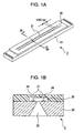
- Figs. 1A and 1B are respectively a perspective view and a sectional view illustrating, in the simplified form, a recording element substrate according to one exemplary embodiment of the present invention.
- Fig. 2 is a perspective view illustrating, in the simplified form, an ink-jet recording head according to the exemplary embodiment of the present invention.
- Fig. 3 is a plan view illustrating, in an enlarged scale, parts of two recording element substrates according to the exemplary embodiment of the present invention.
- Figs. 4A and 4B are explanatory views illustrating a method of manufacturing the ink-jet recording head according to the exemplary embodiment of the present invention.
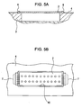
- Figs. 5A and 5B are explanatory views illustrating the method of manufacturing the ink-jet recording head according to the exemplary embodiment of the present invention.
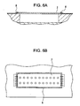
- Figs. 6A and 6B are explanatory views illustrating the method of manufacturing the ink-jet recording head according to the exemplary embodiment of the present invention.
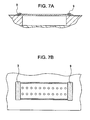
- Figs. 7A and 7B are explanatory views illustrating the method of manufacturing the ink-jet recording head according to the exemplary embodiment of the present invention.
- Fig. 8 is an explanatory view illustrating the method of manufacturing the ink-jet recording head according to the exemplary embodiment of the present invention.
- Fig. 9 is an explanatory view illustrating the method of manufacturing the ink-jet recording head according to the exemplary embodiment of the present invention.
- Fig. 10 is an explanatory view illustrating the method of manufacturing the ink-jet recording head according to the exemplary embodiment of the present invention.
- Fig. 11 is an explanatory view illustrating the method of manufacturing the ink-jet recording head according to the exemplary embodiment of the present invention.
- Fig. 12 is a plan view illustrating, in an enlarged scale, part of the recording element substrate according to the exemplary embodiment of the present invention.
- Fig. 13 is a graph illustrating the results of measuring a distance between reference positions before and after a sealing step for the recording element substrates according to the exemplary embodiment of the present invention.
- Fig. 14 is a graph illustrating the results of measuring respective deviations of the reference positions before and after the sealing step for the recording element substrates according to the exemplary embodiment of the present invention.
- Figs. 15A and 15B are plan views illustrating respective positions of the recording element substrates according to the exemplary embodiment of the present invention before and after the sealing step.
- Figs. 16A and 16B are explanatory views illustrating the method of manufacturing the ink-jet recording head according to the exemplary embodiment of the present invention.
- Figs. 17A and 17B are explanatory views illustrating the method of manufacturing the ink-jet recording head according to the exemplary embodiment of the present invention.
- Fig. 18 is a graph illustrating the measured results of respective deviations of the reference positions before and after the sealing step for the recording element substrate manufactured by the method of manufacturing the ink-jet recording head according to the exemplary embodiment of the present invention.
- Figs. 19A and 19B illustrate the measured results of respective deviations at the reference positions before and after the sealing step for individual recording element substrates according to another exemplary embodiment of the present invention.
- Figs. 20A, 20B and 20C are explanatory views illustrating a method of manufacturing the ink-jet recording head according to another exemplary embodiment of the present invention.
- Fig. 21 is an explanatory view illustrating a method of manufacturing the ink-jet recording head according to still another exemplary embodiment of the present invention.
- Figs. 1A and 1B are respectively a perspective view and a sectional view illustrating, in the simplified form, a recording element substrate 2 used in an ink-jet recording head 1 according to the exemplary embodiment
- Fig. 2 is a perspective view illustrating, in the simplified form, the ink-jet recording head 1 according to the exemplary embodiment
- Fig. 1B is a sectional view taken along a line IB-IB in Fig. 1A .
- the recording element substrate 2 has two nozzle arrays 20 each including a plurality of nozzles 21 to eject ink therefrom.
- the two nozzle arrays 20 are arranged parallel to each other.
- the recording element substrate 2 is made of a Si substrate 22.
- a liquid supply port 23 for supplying ink to the nozzles 21 is bored in a central portion of the Si substrate 22 so as to penetrate the substrate from its front surface to its rear surface.
- a plurality of electro-thermal transducers 24 are disposed at predetermined positions.
- a bubble generating chamber 25 and the nozzles 21 for ejecting the ink are formed by a member made of, e.g., a polymer in a corresponding relation to the electro-thermal transducers 24.
- each of the nozzles 21 has a nozzle diameter of 12 ⁇ m and an ejected ink amount of about 3 pl (pico-liter).
- the nozzles 21 form the nozzle array 20 at a pitch of 1200 dpi, i.e., about 21 ⁇ m, in the lengthwise direction thereof.
- the ink-jet recording head 1 includes eight recording element substrates 2 which are mounted on a supporting member 3 in two zigzag arrays, and the supporting member 3 which supports the recording element substrates 2.
- the recording element substrates 2 are each fixedly bonded to the supporting member 3 by using an adhesive, for example.
- the ink-jet recording head 1 further includes an electric wiring member 4 on which are formed electric wirings (not shown) for supplying signals to the recording element substrates 2.
- the electric wiring member 4 has a plurality of openings 40 ( Fig. 5B ) capable of accommodating the recording element substrates 2, respectively.
- the openings 40 are formed such that, in a state where the electric wiring member 4 is fixedly bonded to the supporting member 3, the recording element substrates 2 are positioned respectively in the openings 40 of the electric wiring member 4.
- a liquid supply member 5 for supplying the ink to the recording element substrates 2 is joined to the underside of the supporting member 3.
- the entire head has a recording width of about 15.75 cm (about 6.2 inches).
- Fig. 3 is a plan view illustrating layout (positions) of two recording element substrates 2 according to the exemplary embodiment on the supporting member 3.
- Each pair of recording element substrates adjacent to each other in a direction (main scanning direction) perpendicular to the direction of the nozzle array 20 in the ink-jet recording head 1 are arranged such that nozzle positions at respective nozzle array ends, which are located close to each other, are overlapped (see a dotted line in Fig. 3 ) as viewed in the main scanning direction.
- the highly accurate arrangement of the nozzle positions is achieved with the method of manufacturing the ink-jet recording head according to the exemplary embodiment.
- the manufacturing method will be described in detail below.
- Figs. 4A , 5A , 6A and 7A are each a sectional view taken along a line IVA to VIIA - IVA to VIIA in Fig. 2
- Figs. 4B , 5B , 6B and 7B are each a plan view of the recording element substrate 2 mounted on the supporting member 3.
- Figs. 4A and 4B illustrate a state where the recording element substrate 2 is mounted to the supporting member 3 and is fixed in place by using an adhesive.
- the recording element substrate 2 includes electrodes (not shown) formed at each of opposite ends thereof to send electric power and recording signals to the electro-thermal transducers 24 of the recording element substrate 2 from the outside.
- the electric wiring member 4 is fixedly bonded to the supporting member 3 such that the recording element substrate 2 is positioned in the opening 40 which is formed in size slightly larger than the recording element substrate 2.
- electric wiring portions 7 are formed by electrically connecting the electrodes of the recording element substrate 2 and electrodes (not shown) of the electric wiring member 4 through wires 6, i.e., by wire bonding, for example.
- a first sealant 8 is coated around the recording element substrate 2 to protect an outer periphery of the recording element substrate 2.
- a second sealant 9 is coated so as to cover the electric wiring portions 7 for protecting the electric wiring portions 7.
- the first sealant 8 and the second sealant 9 are then cured, whereby a unit of the recording element substrate is completed.
- the first sealant 8 serves to protect and reinforce sides of the recording element substrate 2.
- the second sealant 9 serves to protect the electric wiring portions 7.
- the first sealant 8 and the second sealant 9 are fixed to the supporting member 3 and/or the electric wiring member 4.
- the second sealant 9 is desirably made of a material having a high elastic modulus from the viewpoint of protecting the electric wiring portions 7 against externally applied impacts.
- the first sealant 8 and the second sealant 9 are made of materials of the same type for close adhesion therebetween.
- the first sealant 8 is also made of a material having a high elastic modulus.
- the material having a high elastic modulus is used as the first sealant 8 to seal off the surroundings of the recording element substrate 2, there is a possibility that a deformation of the recording element substrate 2 itself and a positional deviation of the recording element substrate 2 on the supporting member 3 may occur due to the following mechanism during the above-described manufacturing process.
- Figs. 8 to 11 are explanatory views illustrating the step of sealing off the surroundings of the recording element substrate 2 and the electric wiring portions 7 formed between the recording element substrate 2 and the electric wiring member 4 with the first sealant 8 and the second sealant 9, respectively.
- Figs. 8 to 11 are each an enlarged sectional view of the electric wiring portion 7.
- Fig. 8 illustrates a state at a point in time where the recording element substrate 2 and the electric wiring member 4 are fixed to the supporting member 3 and electrical connection is completed (i.e., the electric wiring portion 7 is formed).
- An interval (spacing) between the recording element substrate 2 and the electric wiring member 4 in the state of Fig. 8 is assumed to be L1.
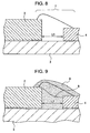
- Fig. 9 illustrates a state at a point in time where the recording element substrate 2 and the electric wiring member 4 are coated with the first sealant 8 and the second sealant 9.
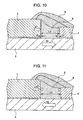
- Fig. 10 illustrates states of relevant components at a curing temperature at which the first and second sealants 8 and 9 are cured.
- the recording element substrate 2 and the supporting member 3 are expanded with a temperature rise (as indicated respectively by arrows K1 and S1 in Fig. 10 ).
- an interval (spacing) L3 between the recording element substrate 2 and the electric wiring member 4 in the state of Fig. 10 is changed from the intervals L1 and L2.
- the sealants are cured in the heating step.
- the recording element substrate 2, the supporting member 3, and the electric wiring member 4 are expanded by the action of heat generated in the thermal curing step. Therefore, the end of the recording element substrate 2 displaces by a distance a and the end of the electric wiring member 4 displaces by a distance b to the right as viewed in Fig. 10 .
- Fig. 11 illustrates a state where, after the curing of the first and second sealants 8 and 9, the temperatures of the relevant components have returned to room temperature and the recording element substrate 2 and the supporting member 3 have contracted with a temperature fall (as indicated respectively by arrows K2 and S2 in Fig. 11 ). If the sealants 8 and 9 are not present, an interval (spacing) L4 between the recording element substrate 2 and the electric wiring member 4 in the state of Fig. 11 is equal to the intervals L1 and L2. However, when the sealants 8 and 9 have difference linear expansion rates from that of, in particular, the supporting member 3, the interval L4 is changed from the intervals L1 and L2 before the end of the curing.
- the amount by which the recording element substrate 2 deforms and its position deviates eventually is determined depending on mainly the following parameters:
- the deformation and the positional deviation of the recording element substrate 2 generate when the temperature of the sealants 8 and 9 falls from the curing temperature after the sealants 8 and 9 have been cured. In other words, that problem occurs even when the recording element substrate 2 and the supporting member 3 have the same linear expansion rate.
- the recording element substrate 2 is a silicon substrate (having dimensions of 24 mm x 7.7 mm x 0.625 mm, an elastic modulus of 100 GPa or more, and a linear expansion rate of about 2.6 ppm).
- the supporting member 3 is an alumina plate (having dimensions of 183 mm x 26 mm x 5 mm, an elastic modulus of about 400 GPa, and a linear expansion rate of about 5 to 7 ppm).
- the first sealant 8 and the second sealant 9 have elastic moduli of about 6 Gpa and about 9 GPa and linear expansion rates of about 25 ppm and about 15 ppm, respectively.
- the interval between the recording element substrate 2 and the electric wiring member 4 at room temperature is about 0.5 mm, and the curing temperature of the sealants is 150°C.
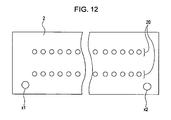
- Fig. 12 is a plan view illustrating, in an enlarged scale, part of the recording element substrate 2 used in the measurement.
- Two reference positions x1 and x2 are set near both ends of the recording element substrate 2, respectively, on a straight line extending parallel to the direction of the nozzle ray 20.
- the deformation and the positional deviation of the recording element substrate 2 are measured on the basis of the reference positions x1 and x2. While the exemplary embodiment is described, for example, in connection with the case where two reference positions are set on the recording element substrate, three or more reference positions may also be set as required.
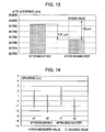
- Fig. 13 illustrates the results of measuring a distance between the two reference positions x1 and x2 after mounting the recording element substrate 2 to the supporting member 3 (i.e., before a sealing step) and after the end of the sealing step. More specifically, each of the results in Fig. 13 indicates an average of values obtained by measuring forty recording element substrates 2.
- the difference between two measured distances substantially represents the lengthwise direction of the recording element substrate 2 between before and after the sealing step, i.e., the amount of actual deformation of the recording element substrate 2 itself, which has generated during the sealing step.
- the difference in the measured distance between before and after the sealing step is 1.34 ⁇ m in average. Taking into account variations occurred in manufacturing the recording element substrates 2, the amount of deformation from the intended distance, i.e., from the design distance (20.8 mm) for the recording element substrate 2, is 1.69 ⁇ m.
- the recording element substrate 2 contracts at least in the direction of the nozzle array 20 through the sealing step.
- the reference positions x1 and x2 deviate in themselves.
- Fig. 14 illustrates the results of measuring the deviations of the reference positions x1 and x2.
- the vertical axis represents respective deviations of the reference positions x1 and x2 from the design values (ideal values) for the recording element substrates 2.
- Each value of the deviations is positive when the reference positions x1 and x2 are moved to the right in the direction of the nozzle array 20 as viewed in Fig. 12 .
- the two reference positions x1 and x2 are moved in directions coming closer to each other through the curing step.
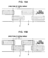
- Figs. 15A and 15B illustrate respective positions of the recording element substrates 2 before and after the sealing step, when the recording element substrates 2 deform as described above. It is here assumed that, as illustrated in Fig. 15A , the recording element substrates 2 are arranged in the mounting step such that respective nozzle array ends of adjacent two of the recording element substrates 2 on each side where those nozzle array ends are overlapped are aligned with each other in the main scanning direction (i.e., positioned to lie on a dotted line in Fig. 15A ). In the above case, each recording element substrate 2 deforms through the sealing step such that both the ends thereof come closer to each other. As a result, the nozzle positions in each recording element substrate 2, in particular, the positions of the nozzle array ends of the recording element substrate 2, are deviated after the sealing step, i.e., after the end of the manufacturing process (see Fig. 15B ).
- the deformation and the positional deviation of the recording element substrate 2, which may generate in the sealing step, are previously obtained on the basis of the above-described measurement results, and the mounted position of the recording element substrate 2 is adjusted in consideration of the measured deformation and positional deviation of the recording element substrate 2.
- a concrete manner of mounting the recording element substrates 2 in consideration of the deformation and the positional deviation thereof will be described below with reference to Figs. 16A and 16B .
- Figs. 16A and 16B are explanatory views illustrating states of the recording element substrates 2 before and after the step of sealing the recording element substrates 2 with the sealants 8 and 9 by the method of manufacturing the ink-jet recording head according to the exemplary embodiment.
- the proper arrangement of the recording element substrates 2 in the ink-jet recording head 1, manufactured by the manufacturing method according to the exemplary embodiment, is as per described above.
- two recording element substrates adjacent to each other in the main scanning direction are arranged such that respective nozzle array ends of the recording element substrates on the side where those nozzle array ends are positioned close to each other are accurately overlapped as viewed in the main scanning direction.
- the following description is made on the concrete manner of mounting the recording element substrates 2 to realize the above-described arrangement with the manufacturing method according to the exemplary embodiment by referring to Figs. 16A and 16B .
- the deviations of the reference positions x1 and x2 after the end of the sealing step are each about 1 ⁇ m as seen from Fig. 14 .
- the recording element substrates 2 are mounted to the supporting member 3 such that the positions of each recording element substrate near the ends thereof are shifted by the same amounts as the respective measured deviations of the reference positions in directions to compensate for those deviations of the reference positions. More specifically, each recording element substrate is mounted in a state where the left end as viewed in Fig. 16A is shifted 1 ⁇ m to the left and the right end as viewed in Fig. 16A is shifted 1 ⁇ m to the right.
- Fig. 16A is shifted 1 ⁇ m to the right.
- the recording element substrates 2 are mounted to the supporting member 3 such that the distance between the nozzles at respective nozzle array ends of the recording element substrates 2 adjacent to each other is set to 2 ⁇ m in total, which represents a correction amount X. Consequently, the desired arrangement, i.e., the arrangement illustrated in Fig. 16B , can be realized in the state after the manufacturing process as the result of the deformations and the positional deviations of the recording element substrates 2, which generate during the sealing step.
- Figs. 17A and 17B illustrate states of the plural recording element substrates 2 before and after the sealing step, respectively, in consideration of the deformation and the positional deviation of each recording element substrate 2.
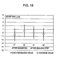
- Fig. 18 illustrates the results of verifying whether the deviations of the reference positions are actually corrected by using the above-described manufacturing method. Measurement conditions, etc. are the same as those described above with reference to Fig. 14 .
- the positional deviations of the recording element substrates 2, which generate during the manufacturing process, are measured in advance and the recording element substrates are mounted to the supporting member 3 at the positions adapted to compensate for the measured positional deviations. Therefore, the recording element substrates 2 after the end of the manufacturing process can be arranged at the desired positions with a high degree of accuracy, and high-definition and high-quality recording can be realized even with a long ink-jet recording head.
- the average value of the positional deviations of the plural recording element substrates 2 is used as the amount for correcting the deformation and the positional deviation generated in each of the recording element substrates 2, and the mounted positions of the recording element substrates 2 are all corrected by a certain fixed amount.
- the mounted positions of the recording element substrates 2 can be adjusted for each substrate depending on the amount of the deformation thereof.
- Fig. 19A illustrates the results of measuring the positional deviations of the recording element substrates 2 after the sealing step at 8 sets of 16 reference positions in total when eight recording element substrates 2 are mounted to the supporting member 3.
- Fig. 19B illustrates respective positions of the recording element substrates 2 on the supporting member 3. Measurement conditions, etc., including the reference positions x1 and x2, are the same as those described above with reference to Figs. 14 and 18 .
- the recording element substrate 2 arranged nearer to the end of the supporting member 3 tends to deform in a larger deviation than that of the recording element substrate 2 arranged nearer to the center of the supporting member 3.
- the recording element substrates 2 can be each caused to move depending on the positional deviation thereof by using, as the correction amount, the positional deviation of each recording element substrate 2.
- the mounted position of each recording element substrate can be adjusted as illustrated in Figs. 20A and 20B .
- each recording element substrate 2 can be adjusted such that correction amounts X1 and X2 in a region C near the center of the supporting member 3 and in a region D near the end thereof (see Fig. 20A ), respectively, are set to be X1 ⁇ X2 (see Figs. 20B and 20C ).
- the recording element substrates 2 can be each held at the desired position after the sealing step, and the ink-jet recording head including the recording element substrates 2 arranged with a higher degree of accuracy can be obtained.
- the actual positional deviations of the recording element substrates 2 are determined depending on the shapes, the dimensions, the physical properties, etc. of the relevant components. Adjusting the mounted position of each recording element substrate 2 depending on the positional deviation thereof, as described above, is also advantageous in being adaptable for changes in positional deviations of the individual recording element substrates 2 that may occur based on differences in constructions of the recording element substrates 2.
- the direction in which the mounted positions are corrected is not limited to the nozzle array direction.
- the mounted positions can also be corrected in the main scanning direction that is perpendicular to the nozzle array direction.
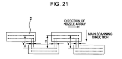
- the mounted positions of the plural recording element substrates 2 can be adjusted such that those substrates are arranged parallel to each other, as viewed in the nozzle array direction, with a high degree of accuracy while intervals (distances) Y in Fig. 21 are held constant after the sealing step.
- An embodiment of the present invention can provide a method of manufacturing an ink-jet recording head (1) including a plurality of recording element substrates (2) each having at least one nozzle array (20) comprising a plurality of nozzles (21) to eject ink, an electric wiring member (4) arranged to supply signals to the plurality of recording element substrates, a supporting member (3) arranged to support the plurality of recording element substrates and the electric wiring member, electric connecting portions (7) electrically interconnecting the recording element substrates and the electric wiring member, and a sealant (9) sealing the electric connecting portions, the method comprising the steps of: applying sealants (8, 9) to the supporting member including the recording element substrates, the electric wiring member, and the electric connecting portions, and curing the applied sealants by heating the sealants; measuring a distance between at least two reference positions set on each of the recording element substrates before and after the curing of the sealants; and mounting the plurality of recording element substrates to the supporting member depending on a difference in the distance between the reference positions measured in the measuring step before and after the
- the difference in the distance is measured in the measuring step based on two reference positions (x1, x2) set near both ends of each of the recording element substrates.
- the two reference positions are located apart from each other in a direction of the nozzle array.
- the difference in the distance is measured in the measuring step in a direction of the nozzle array.
- the difference in the distance is measured in the measuring step in a direction perpendicular to a direction of the nozzle array.
- the difference in the distance between the two reference positions is measured in the measuring step for each of the recording element substrates, and each of the recording element substrates is mounted in the mounting step depending on an average value of the measured differences in the distances between every two reference positions on the individual recording element substrates.
- an ink-jet recording head (1) including a plurality of recording element substrates (2) each having at least one ejection orifice array (20) comprising a plurality of ejection orifices (21) to eject ink, an electric wiring member (4) arranged to supply signals to the plurality of recording element substrates, a supporting member (3) arranged to support the plurality of recording element substrates and the electric wiring member, electric connecting portions (7) electrically interconnecting the recording element substrates and the electric wiring member, and a sealant (9) sealing the electric connecting portions, the method comprising the steps of: mounting the plurality of recording element substrates to the supporting member depending on a difference between an interval of two reference positions on each of the recording element substrates disposed on the supporting member before curing of the sealant and an interval of the two reference positions after the curing of the sealant, the difference being measured in advance, such that positions of the ejection orifices at respective ends of the ejection orifice arrays in adjacent two of the plurality
Abstract
Description
- The present invention relates to a method of manufacturing an ink-jet recording head.
- Hitherto, ink-jet recording apparatuses have been widely commercialized and utilized in, e.g., output devices of computers, etc, for the reasons that the running cost is relatively low, the apparatus size can be reduced, and the ink-jet recording apparatus is easily adaptable for color image recording using inks of plural colors.
- On the other hand, an energy generating element for generating energy to eject ink from an ejection orifice of a recording head is practiced, for example, as the type using an electro-mechanical transducer, e.g., a piezoelectric element, or the type irradiating electromagnetic waves emitted from, e.g., a laser for heating ink and ejecting ink droplets by the action of the heating. Another known example of the energy generating element is the type heating a liquid by an electro-thermal transducer having a heating resistor.
- In particular, a recording head of the ink-jet recording of the type ejecting ink droplets by utilizing thermal energy is advantageous in that ejection orifices can be arrayed at a high density and an image can be recorded at a high resolution. Above all, a recording head using an electro-thermal transducer as energy generating element is effective in easily reducing a head size. Further, the recording head using the electro-thermal transducer is advantageous in that the recording head can be manufactured by sufficiently utilizing merits of the IC techniques and the micro-machining techniques where advancement and reliability have been recently progressed and improved to a remarkable extent in semiconductor fields, and that the recording head can be easily manufactured at a higher density packing and at a lower cost.
- In recent years, a method of manufacturing a nozzle, which ejects ink, with a high degree of accuracy by employing the photolithography has also been utilized to perform recording at a higher definition. Of late, a recording head having a longer recording width is further demanded from the viewpoint of realizing recording of an image at a higher speed and a higher definition. More specifically, there is a demand for a recording head with a length of 10.16 cm (4 inches) to 30.48 cm (12 inches), for example.
- When trying to realize the recording head having such a long recording width by forming a larger number of recording elements on a single recording element substrate, the length of the recording element substrate is so increased as to cause the problem that the recording element substrate is more susceptible to, e.g., cracks and warping. Another problem of the recording element substrate having a very long size is that the yield of the recording element substrate itself reduces in the manufacturing process.
- One proposal for overcoming the above-mentioned problems is to arrange, on an integral carrier, a plurality of recording element substrates each having a nozzle array which includes an appropriate number of nozzles, and to realize a recording head having a large recording width as a whole. The proposed construction requires that nozzles of the recording element substrates adjacent to each other are partly overlapped and are accurately arranged to prevent gaps and overlaps from generating in a printed image. In particular, when photographic print is intended or when an even longer recording head is to be formed, requirements for the accuracy in nozzle positions are further increased. Above all, in an overlapped region between the recording element substrates adjacent to each other, a deviation of the nozzle position is more apt to appear as a streak in the printed result, and the nozzle position is especially required to satisfy an even higher degree of accuracy.
- PCT Japanese Translation Patent Publication No.
2003-525786 - However, the disclosed method is just intended to cope with the position deviation caused by the difference between the temperature during the manufacturing and the temperature during the use. In other words, the disclosed method does not take into consideration various deviations that may generate in the recording element substrate throughout the entire manufacturing process. If those various deviations generate, the recording element substrate and the positions of nozzles formed therein cannot be arranged at the intended positions with a high degree of accuracy.
US 2007/0046738 discloses a structure including a base plate and a formation unit. The formation unit is bonded and fixed to and retained on the base plate by a first adhesive. The first adhesive is disposed at least in the vicinities of end portions of a peripheral edge of a bonding surface of the formation unit. - An exemplary embodiment of the present invention provides a method of manufacturing an ink-jet recording head, which enables respective positions of recording element substrates after a manufacturing process to be arranged at the desired positions with a high degree of accuracy.
- The present invention provides in a first aspect a method of manufacturing an ink-jet recording head as specified in
claims 1 to 13. - The present invention provides in a second aspect provides a method of determining a compensation amount as specified in claim 14.
- The present invention provides in a third aspect provides a method of manufacturing an ink-jet recording head as specified in claim 15.
- With the exemplary embodiment of the present invention, the method of manufacturing the ink-jet recording head can be provided which enables respective positions of the recording element substrates after the manufacturing process to be arranged at the desired positions with a high degree of accuracy.
- Further features of the present invention will become apparent from the following description of exemplary embodiments with reference to the attached drawings.
-
Figs. 1A and 1B are respectively a perspective view and a sectional view illustrating, in the simplified form, a recording element substrate according to one exemplary embodiment of the present invention. -
Fig. 2 is a perspective view illustrating, in the simplified form, an ink-jet recording head according to the exemplary embodiment of the present invention. -
Fig. 3 is a plan view illustrating, in an enlarged scale, parts of two recording element substrates according to the exemplary embodiment of the present invention. -
Figs. 4A and 4B are explanatory views illustrating a method of manufacturing the ink-jet recording head according to the exemplary embodiment of the present invention. -
Figs. 5A and 5B are explanatory views illustrating the method of manufacturing the ink-jet recording head according to the exemplary embodiment of the present invention. -
Figs. 6A and 6B are explanatory views illustrating the method of manufacturing the ink-jet recording head according to the exemplary embodiment of the present invention. -
Figs. 7A and 7B are explanatory views illustrating the method of manufacturing the ink-jet recording head according to the exemplary embodiment of the present invention. -
Fig. 8 is an explanatory view illustrating the method of manufacturing the ink-jet recording head according to the exemplary embodiment of the present invention. -
Fig. 9 is an explanatory view illustrating the method of manufacturing the ink-jet recording head according to the exemplary embodiment of the present invention. -
Fig. 10 is an explanatory view illustrating the method of manufacturing the ink-jet recording head according to the exemplary embodiment of the present invention. -
Fig. 11 is an explanatory view illustrating the method of manufacturing the ink-jet recording head according to the exemplary embodiment of the present invention. -
Fig. 12 is a plan view illustrating, in an enlarged scale, part of the recording element substrate according to the exemplary embodiment of the present invention. -
Fig. 13 is a graph illustrating the results of measuring a distance between reference positions before and after a sealing step for the recording element substrates according to the exemplary embodiment of the present invention. -
Fig. 14 is a graph illustrating the results of measuring respective deviations of the reference positions before and after the sealing step for the recording element substrates according to the exemplary embodiment of the present invention. -
Figs. 15A and 15B are plan views illustrating respective positions of the recording element substrates according to the exemplary embodiment of the present invention before and after the sealing step. -
Figs. 16A and 16B are explanatory views illustrating the method of manufacturing the ink-jet recording head according to the exemplary embodiment of the present invention. -
Figs. 17A and 17B are explanatory views illustrating the method of manufacturing the ink-jet recording head according to the exemplary embodiment of the present invention. -
Fig. 18 is a graph illustrating the measured results of respective deviations of the reference positions before and after the sealing step for the recording element substrate manufactured by the method of manufacturing the ink-jet recording head according to the exemplary embodiment of the present invention. -
Figs. 19A and 19B illustrate the measured results of respective deviations at the reference positions before and after the sealing step for individual recording element substrates according to another exemplary embodiment of the present invention. -
Figs. 20A, 20B and 20C are explanatory views illustrating a method of manufacturing the ink-jet recording head according to another exemplary embodiment of the present invention. -
Fig. 21 is an explanatory view illustrating a method of manufacturing the ink-jet recording head according to still another exemplary embodiment of the present invention. - An ink-jet recording head and a method of manufacturing the ink-jet recording head, according to one exemplary embodiment of the present invention, will be described below with reference to the drawings.
- The construction of the ink-jet recording head according to the exemplary embodiment is first described.
-
Figs. 1A and 1B are respectively a perspective view and a sectional view illustrating, in the simplified form, arecording element substrate 2 used in an ink-jet recording head 1 according to the exemplary embodiment, andFig. 2 is a perspective view illustrating, in the simplified form, the ink-jet recording head 1 according to the exemplary embodiment.Fig. 1B is a sectional view taken along a line IB-IB inFig. 1A . - As illustrated in
Fig. 1A , therecording element substrate 2 according to the exemplary embodiment has twonozzle arrays 20 each including a plurality ofnozzles 21 to eject ink therefrom. The twonozzle arrays 20 are arranged parallel to each other. Therecording element substrate 2 is made of aSi substrate 22. As illustrated inFig. 1B , aliquid supply port 23 for supplying ink to thenozzles 21 is bored in a central portion of theSi substrate 22 so as to penetrate the substrate from its front surface to its rear surface. On the front surface of theSi substrate 22, a plurality of electro-thermal transducers 24 are disposed at predetermined positions. Abubble generating chamber 25 and thenozzles 21 for ejecting the ink are formed by a member made of, e.g., a polymer in a corresponding relation to the electro-thermal transducers 24. In the exemplary embodiment, each of thenozzles 21 has a nozzle diameter of 12 µm and an ejected ink amount of about 3 pl (pico-liter). Thenozzles 21 form thenozzle array 20 at a pitch of 1200 dpi, i.e., about 21 µm, in the lengthwise direction thereof. - As illustrated in
Fig. 2 , the ink-jet recording head 1 according to the exemplary embodiment includes eightrecording element substrates 2 which are mounted on a supportingmember 3 in two zigzag arrays, and the supportingmember 3 which supports therecording element substrates 2. Therecording element substrates 2 are each fixedly bonded to the supportingmember 3 by using an adhesive, for example. The ink-jet recording head 1 further includes anelectric wiring member 4 on which are formed electric wirings (not shown) for supplying signals to therecording element substrates 2. Theelectric wiring member 4 has a plurality of openings 40 (Fig. 5B ) capable of accommodating therecording element substrates 2, respectively. Theopenings 40 are formed such that, in a state where theelectric wiring member 4 is fixedly bonded to the supportingmember 3, therecording element substrates 2 are positioned respectively in theopenings 40 of theelectric wiring member 4. Aliquid supply member 5 for supplying the ink to therecording element substrates 2 is joined to the underside of the supportingmember 3. In the exemplary embodiment in which eightrecording element substrates 2 are mounted on the ink-jet recording head 1, the entire head has a recording width of about 15.75 cm (about 6.2 inches). -
Fig. 3 is a plan view illustrating layout (positions) of tworecording element substrates 2 according to the exemplary embodiment on the supportingmember 3. - Each pair of recording element substrates adjacent to each other in a direction (main scanning direction) perpendicular to the direction of the
nozzle array 20 in the ink-jet recording head 1 are arranged such that nozzle positions at respective nozzle array ends, which are located close to each other, are overlapped (see a dotted line inFig. 3 ) as viewed in the main scanning direction. With such an arrangement that the nozzle positions in therecording element substrates 2 adjacent to each other in the main scanning direction are properly overlapped as viewed in the main scanning direction, it is possible to realize the ink-jet recording head 1 which can prevent gaps and overlaps from generating in a printed image, and which can perform recording of the image at a high definition. - The highly accurate arrangement of the nozzle positions is achieved with the method of manufacturing the ink-jet recording head according to the exemplary embodiment. The manufacturing method will be described in detail below.
- Regarding the process of manufacturing the ink-jet recording head, particularly, part from a step of mounting the
recording element substrates 2 to the supportingmember 3 to a step of sealing those substrates with a sealant is first described with reference toFigs. 4 to 7 .Figs. 4A ,5A ,6A and7A are each a sectional view taken along a line IVA to VIIA - IVA to VIIA inFig. 2 , andFigs. 4B ,5B ,6B and7B are each a plan view of therecording element substrate 2 mounted on the supportingmember 3. -
Figs. 4A and 4B illustrate a state where therecording element substrate 2 is mounted to the supportingmember 3 and is fixed in place by using an adhesive. Therecording element substrate 2 includes electrodes (not shown) formed at each of opposite ends thereof to send electric power and recording signals to the electro-thermal transducers 24 of therecording element substrate 2 from the outside. - Next, as illustrated in
Figs. 5A and 5B , theelectric wiring member 4 is fixedly bonded to the supportingmember 3 such that therecording element substrate 2 is positioned in theopening 40 which is formed in size slightly larger than therecording element substrate 2. Thereafter,electric wiring portions 7 are formed by electrically connecting the electrodes of therecording element substrate 2 and electrodes (not shown) of theelectric wiring member 4 throughwires 6, i.e., by wire bonding, for example. - Next, as illustrated in
Figs. 6A and 6B , afirst sealant 8 is coated around therecording element substrate 2 to protect an outer periphery of therecording element substrate 2. Successively, as illustrated inFigs. 7A and 7B , asecond sealant 9 is coated so as to cover theelectric wiring portions 7 for protecting theelectric wiring portions 7. Thefirst sealant 8 and thesecond sealant 9 are then cured, whereby a unit of the recording element substrate is completed. - In the above-described process, the
first sealant 8 serves to protect and reinforce sides of therecording element substrate 2. Thesecond sealant 9 serves to protect theelectric wiring portions 7. Thefirst sealant 8 and thesecond sealant 9 are fixed to the supportingmember 3 and/or theelectric wiring member 4. Thesecond sealant 9 is desirably made of a material having a high elastic modulus from the viewpoint of protecting theelectric wiring portions 7 against externally applied impacts. On the other hand, from the viewpoint of ensuring high reliability for a long term, it is effective that thefirst sealant 8 and thesecond sealant 9 are made of materials of the same type for close adhesion therebetween. In such a case, thefirst sealant 8 is also made of a material having a high elastic modulus. - When the material having a high elastic modulus is used as the
first sealant 8 to seal off the surroundings of therecording element substrate 2, there is a possibility that a deformation of therecording element substrate 2 itself and a positional deviation of therecording element substrate 2 on the supportingmember 3 may occur due to the following mechanism during the above-described manufacturing process. - The deformation and the positional deviation of the
recording element substrate 2, which may occur during the manufacturing process of the ink-jet recording head 1, will be described below with reference toFigs. 8 to 11 . -
Figs. 8 to 11 are explanatory views illustrating the step of sealing off the surroundings of therecording element substrate 2 and theelectric wiring portions 7 formed between therecording element substrate 2 and theelectric wiring member 4 with thefirst sealant 8 and thesecond sealant 9, respectively.Figs. 8 to 11 are each an enlarged sectional view of theelectric wiring portion 7. -
Fig. 8 illustrates a state at a point in time where therecording element substrate 2 and theelectric wiring member 4 are fixed to the supportingmember 3 and electrical connection is completed (i.e., theelectric wiring portion 7 is formed). An interval (spacing) between therecording element substrate 2 and theelectric wiring member 4 in the state ofFig. 8 is assumed to be L1. -
Fig. 9 illustrates a state at a point in time where therecording element substrate 2 and theelectric wiring member 4 are coated with thefirst sealant 8 and thesecond sealant 9. The length along which thefirst sealant 8 and the supportingmember 3 contact with each other, i.e., an interval (spacing) between therecording element substrate 2 and theelectric wiring member 4, in the state ofFig. 9 is assumed to be L2. In this state, the relationship of L2 = L1 still holds. -
Fig. 10 illustrates states of relevant components at a curing temperature at which the first andsecond sealants recording element substrate 2 and the supportingmember 3 are expanded with a temperature rise (as indicated respectively by arrows K1 and S1 inFig. 10 ). Accordingly, an interval (spacing) L3 between therecording element substrate 2 and theelectric wiring member 4 in the state ofFig. 10 is changed from the intervals L1 and L2. In the exemplary embodiment, because the linear expansion rate of the supportingmember 3 is larger than that of therecording element substrate 2, the relationship of (L1 = L2) < L3 is resulted. The sealants are cured in the heating step. To describe in more detail with reference toFig. 10 , therecording element substrate 2, the supportingmember 3, and theelectric wiring member 4 are expanded by the action of heat generated in the thermal curing step. Therefore, the end of therecording element substrate 2 displaces by a distance a and the end of theelectric wiring member 4 displaces by a distance b to the right as viewed inFig. 10 . -
Fig. 11 illustrates a state where, after the curing of the first andsecond sealants recording element substrate 2 and the supportingmember 3 have contracted with a temperature fall (as indicated respectively by arrows K2 and S2 inFig. 11 ). If thesealants recording element substrate 2 and theelectric wiring member 4 in the state ofFig. 11 is equal to the intervals L1 and L2. However, when thesealants member 3, the interval L4 is changed from the intervals L1 and L2 before the end of the curing. Accordingly, stresses are imposed on therecording element substrate 2, thus causing the deformation and the positional deviation of therecording element substrate 2. The generated stresses increase particularly when the elastic modulus of thefirst sealant 8 is high. Because the sealants are already cured in the state ofFig. 11 , therecording element substrate 2 contracts to such an extent as exceeding the distance through which it has expanded. Thus, the relationship of (L1 = L2) < L4 <L3 is resulted. In other words, the end of therecording element substrate 2 displaces by a distance a' to the left as viewed inFig. 11 . Because thesealants - The amount by which the
recording element substrate 2 deforms and its position deviates eventually is determined depending on mainly the following parameters: - Linear expansion rate, dimensions, and elastic modulus of the
recording element substrate 2 - Linear expansion rate, dimensions, and elastic modulus of the supporting
member 3 - Linear expansion rates, elastic moduli, amounts, and curing temperature of the
sealants - Dimensions of an area where the
first sealant 8 contacts the supportingmember 3 - The deformation and the positional deviation of the
recording element substrate 2 generate when the temperature of thesealants sealants recording element substrate 2 and the supportingmember 3 have the same linear expansion rate. - The results of actually measuring the deformation and the positional deviation of the
recording element substrate 2 in tests for improving the method of manufacturing the ink-jet recording head according to the exemplary embodiment will be described in detail below with reference toFigs. 12 to 14 . - Dimensions and physical property values of the individual components of the ink-
jet recording head 1 used in measuring the deformation and the positional deviation of therecording element substrate 2 are as follows. - The
recording element substrate 2 is a silicon substrate (having dimensions of 24 mm x 7.7 mm x 0.625 mm, an elastic modulus of 100 GPa or more, and a linear expansion rate of about 2.6 ppm). The supportingmember 3 is an alumina plate (having dimensions of 183 mm x 26 mm x 5 mm, an elastic modulus of about 400 GPa, and a linear expansion rate of about 5 to 7 ppm). Thefirst sealant 8 and thesecond sealant 9 have elastic moduli of about 6 Gpa and about 9 GPa and linear expansion rates of about 25 ppm and about 15 ppm, respectively. The interval between therecording element substrate 2 and theelectric wiring member 4 at room temperature is about 0.5 mm, and the curing temperature of the sealants is 150°C. -
Fig. 12 is a plan view illustrating, in an enlarged scale, part of therecording element substrate 2 used in the measurement. Two reference positions x1 and x2 are set near both ends of therecording element substrate 2, respectively, on a straight line extending parallel to the direction of thenozzle ray 20. The deformation and the positional deviation of therecording element substrate 2 are measured on the basis of the reference positions x1 and x2. While the exemplary embodiment is described, for example, in connection with the case where two reference positions are set on the recording element substrate, three or more reference positions may also be set as required. -
Fig. 13 illustrates the results of measuring a distance between the two reference positions x1 and x2 after mounting therecording element substrate 2 to the supporting member 3 (i.e., before a sealing step) and after the end of the sealing step. More specifically, each of the results inFig. 13 indicates an average of values obtained by measuring fortyrecording element substrates 2. The difference between two measured distances substantially represents the lengthwise direction of therecording element substrate 2 between before and after the sealing step, i.e., the amount of actual deformation of therecording element substrate 2 itself, which has generated during the sealing step. The difference in the measured distance between before and after the sealing step is 1.34 µm in average. Taking into account variations occurred in manufacturing therecording element substrates 2, the amount of deformation from the intended distance, i.e., from the design distance (20.8 mm) for therecording element substrate 2, is 1.69 µm. - Thus, in the case of the ink-
jet recording head 1 having the above-described construction, therecording element substrate 2 contracts at least in the direction of thenozzle array 20 through the sealing step. Further, the reference positions x1 and x2 deviate in themselves.Fig. 14 illustrates the results of measuring the deviations of the reference positions x1 and x2. InFig. 14 , the vertical axis represents respective deviations of the reference positions x1 and x2 from the design values (ideal values) for therecording element substrates 2. Each value of the deviations is positive when the reference positions x1 and x2 are moved to the right in the direction of thenozzle array 20 as viewed inFig. 12 . Thus, as seen fromFig. 14 , the two reference positions x1 and x2 are moved in directions coming closer to each other through the curing step. -
Figs. 15A and 15B illustrate respective positions of therecording element substrates 2 before and after the sealing step, when therecording element substrates 2 deform as described above. It is here assumed that, as illustrated inFig. 15A , therecording element substrates 2 are arranged in the mounting step such that respective nozzle array ends of adjacent two of therecording element substrates 2 on each side where those nozzle array ends are overlapped are aligned with each other in the main scanning direction (i.e., positioned to lie on a dotted line inFig. 15A ). In the above case, eachrecording element substrate 2 deforms through the sealing step such that both the ends thereof come closer to each other. As a result, the nozzle positions in eachrecording element substrate 2, in particular, the positions of the nozzle array ends of therecording element substrate 2, are deviated after the sealing step, i.e., after the end of the manufacturing process (seeFig. 15B ). - With the method of manufacturing the ink-
jet recording head 1 according to the exemplary embodiment, the deformation and the positional deviation of therecording element substrate 2, which may generate in the sealing step, are previously obtained on the basis of the above-described measurement results, and the mounted position of therecording element substrate 2 is adjusted in consideration of the measured deformation and positional deviation of therecording element substrate 2. A concrete manner of mounting therecording element substrates 2 in consideration of the deformation and the positional deviation thereof will be described below with reference toFigs. 16A and 16B . -
Figs. 16A and 16B are explanatory views illustrating states of therecording element substrates 2 before and after the step of sealing therecording element substrates 2 with thesealants - The proper arrangement of the
recording element substrates 2 in the ink-jet recording head 1, manufactured by the manufacturing method according to the exemplary embodiment, is as per described above. Stated another way, in order to realize high-definition recording by a long recording head, as illustrated inFig. 16B , two recording element substrates adjacent to each other in the main scanning direction are arranged such that respective nozzle array ends of the recording element substrates on the side where those nozzle array ends are positioned close to each other are accurately overlapped as viewed in the main scanning direction. The following description is made on the concrete manner of mounting therecording element substrates 2 to realize the above-described arrangement with the manufacturing method according to the exemplary embodiment by referring toFigs. 16A and 16B . - The deviations of the reference positions x1 and x2 after the end of the sealing step are each about 1 µm as seen from
Fig. 14 . With the manufacturing method according to the exemplary embodiment, therefore, therecording element substrates 2 are mounted to the supportingmember 3 such that the positions of each recording element substrate near the ends thereof are shifted by the same amounts as the respective measured deviations of the reference positions in directions to compensate for those deviations of the reference positions. More specifically, each recording element substrate is mounted in a state where the left end as viewed inFig. 16A is shifted 1 µm to the left and the right end as viewed inFig. 16A is shifted 1 µm to the right. Thus, as illustrated inFig. 16A , therecording element substrates 2 are mounted to the supportingmember 3 such that the distance between the nozzles at respective nozzle array ends of therecording element substrates 2 adjacent to each other is set to 2 µm in total, which represents a correction amount X. Consequently, the desired arrangement, i.e., the arrangement illustrated inFig. 16B , can be realized in the state after the manufacturing process as the result of the deformations and the positional deviations of therecording element substrates 2, which generate during the sealing step.Figs. 17A and 17B illustrate states of the pluralrecording element substrates 2 before and after the sealing step, respectively, in consideration of the deformation and the positional deviation of eachrecording element substrate 2. -
Fig. 18 illustrates the results of verifying whether the deviations of the reference positions are actually corrected by using the above-described manufacturing method. Measurement conditions, etc. are the same as those described above with reference toFig. 14 . By employing the manufacturing method according to the exemplary embodiment, as seen fromFig. 18 , the reference positions x1 and x2 are located at positions closer to the desired ones (deviation = 0) after the sealing step than those illustrated inFig. 14 . - With the method of manufacturing the ink-jet recording head according to the exemplary embodiment, the positional deviations of the
recording element substrates 2, which generate during the manufacturing process, are measured in advance and the recording element substrates are mounted to the supportingmember 3 at the positions adapted to compensate for the measured positional deviations. Therefore, therecording element substrates 2 after the end of the manufacturing process can be arranged at the desired positions with a high degree of accuracy, and high-definition and high-quality recording can be realized even with a long ink-jet recording head. - In the above-described exemplary embodiment, the average value of the positional deviations of the plural
recording element substrates 2 is used as the amount for correcting the deformation and the positional deviation generated in each of therecording element substrates 2, and the mounted positions of therecording element substrates 2 are all corrected by a certain fixed amount. According to another exemplary embodiment of the present invention, when the deformations of therecording element substrates 2 differ in amounts from each other, the mounted positions of therecording element substrates 2 can be adjusted for each substrate depending on the amount of the deformation thereof. -
Fig. 19A illustrates the results of measuring the positional deviations of therecording element substrates 2 after the sealing step at 8 sets of 16 reference positions in total when eightrecording element substrates 2 are mounted to the supportingmember 3.Fig. 19B illustrates respective positions of therecording element substrates 2 on the supportingmember 3. Measurement conditions, etc., including the reference positions x1 and x2, are the same as those described above with reference toFigs. 14 and18 . - As seen from
Fig. 19A , therecording element substrate 2 arranged nearer to the end of the supportingmember 3 tends to deform in a larger deviation than that of therecording element substrate 2 arranged nearer to the center of the supportingmember 3. In such a case, when therecording element substrates 2 are mounted to the supportingmember 3, therecording element substrates 2 can be each caused to move depending on the positional deviation thereof by using, as the correction amount, the positional deviation of eachrecording element substrate 2. In practice, the mounted position of each recording element substrate can be adjusted as illustrated inFigs. 20A and 20B . More specifically, the mounted position of eachrecording element substrate 2 can be adjusted such that correction amounts X1 and X2 in a region C near the center of the supportingmember 3 and in a region D near the end thereof (seeFig. 20A ), respectively, are set to be X1 < X2 (seeFigs. 20B and 20C ). As a result, therecording element substrates 2 can be each held at the desired position after the sealing step, and the ink-jet recording head including therecording element substrates 2 arranged with a higher degree of accuracy can be obtained. - While, in the above-described measurement, the
recording element substrates 2 generate a larger positional deviation near the end of the supportingmember 3 than the center thereof, the actual positional deviations of therecording element substrates 2 are determined depending on the shapes, the dimensions, the physical properties, etc. of the relevant components. Adjusting the mounted position of eachrecording element substrate 2 depending on the positional deviation thereof, as described above, is also advantageous in being adaptable for changes in positional deviations of the individualrecording element substrates 2 that may occur based on differences in constructions of therecording element substrates 2. - While the above description has been made as correcting the mounted positions of the
recording element substrates 2 only in the nozzle array direction, the direction in which the mounted positions are corrected is not limited to the nozzle array direction. As illustrated inFig. 21 , the mounted positions can also be corrected in the main scanning direction that is perpendicular to the nozzle array direction. For example, the mounted positions of the pluralrecording element substrates 2 can be adjusted such that those substrates are arranged parallel to each other, as viewed in the nozzle array direction, with a high degree of accuracy while intervals (distances) Y inFig. 21 are held constant after the sealing step. - Additionally, in order to maximize the advantages of the above-described method of manufacturing the ink-jet recording head, variations in the deformations and the positional deviations of the
recording element substrates 2 require to be suppressed minimum. From that point of view, it is important to closely control the amount of the applied sealant because the deformation and the positional deviation of eachrecording element substrate 2 changes depending on, e.g., variations in the amount of thefirst sealant 8 applied.
An embodiment of the present invention can provide a method of manufacturing an ink-jet recording head (1) including a plurality of recording element substrates (2) each having at least one nozzle array (20) comprising a plurality of nozzles (21) to eject ink, an electric wiring member (4) arranged to supply signals to the plurality of recording element substrates, a supporting member (3) arranged to support the plurality of recording element substrates and the electric wiring member, electric connecting portions (7) electrically interconnecting the recording element substrates and the electric wiring member, and a sealant (9) sealing the electric connecting portions, the method comprising the steps of: applying sealants (8, 9) to the supporting member including the recording element substrates, the electric wiring member, and the electric connecting portions, and curing the applied sealants by heating the sealants; measuring a distance between at least two reference positions set on each of the recording element substrates before and after the curing of the sealants; and mounting the plurality of recording element substrates to the supporting member depending on a difference in the distance between the reference positions measured in the measuring step before and after the curing of the sealants.
In such a method, the difference in the distance is measured in the measuring step based on two reference positions (x1, x2) set near both ends of each of the recording element substrates.
Preferably, the two reference positions are located apart from each other in a direction of the nozzle array.
Preferably, the difference in the distance is measured in the measuring step in a direction of the nozzle array.
Preferably, the difference in the distance is measured in the measuring step in a direction perpendicular to a direction of the nozzle array.
Preferably, the difference in the distance between the two reference positions is measured in the measuring step for each of the recording element substrates, and each of the recording element substrates is mounted in the mounting step depending on an average value of the measured differences in the distances between every two reference positions on the individual recording element substrates.
In another embodiment of the invention a method of manufacturing an ink-jet recording head (1) including a plurality of recording element substrates (2) each having at least one ejection orifice array (20) comprising a plurality of ejection orifices (21) to eject ink, an electric wiring member (4) arranged to supply signals to the plurality of recording element substrates, a supporting member (3) arranged to support the plurality of recording element substrates and the electric wiring member, electric connecting portions (7) electrically interconnecting the recording element substrates and the electric wiring member, and a sealant (9) sealing the electric connecting portions, the method comprising the steps of: mounting the plurality of recording element substrates to the supporting member depending on a difference between an interval of two reference positions on each of the recording element substrates disposed on the supporting member before curing of the sealant and an interval of the two reference positions after the curing of the sealant, the difference being measured in advance, such that positions of the ejection orifices at respective ends of the ejection orifice arrays in adjacent two of the plurality of recording element substrates, on the side where the respective ends are positioned close to each other, are shifted in a direction of the ejection orifice array; electrically connecting the electric wiring member and the recording element substrates to each other; and applying the sealant to the electric connecting portions and curing the applied sealant by heating the sealant.
Claims (15)
- A method of manufacturing an ink-jet recording head (1) including a plurality of recording element substrates (2) each having at least one nozzle array (20) comprising a plurality of nozzles (21) to eject ink and a supporting member (3) for supporting the plurality of recording element substrates (2), the method comprising the steps of:mounting a first plurality of recording element substrates (2) to a first supporting member (3) of a first ink-jet recording head;applying sealant (8) to the first supporting member (3) and around each of the first plurality of recording element substrates (2) of the first ink-jet recording head (1) for protecting an outer periphery of each of the first plurality of recording element substrates (2), and curing the applied sealant;measuring a distance between at least two reference positions (x1,x2) set on at least one of the first plurality of recording element substrates (2) of the first ink-jet recording head (1) before and after the curing of the sealant; andmounting a second plurality of recording element substrates (2) to a second supporting member (3) of a second ink-jet recording head (1) depending on a difference in the distance between the reference positions measured in the measuring step carried out on the first ink-jet recording head before and after the curing of the sealant.
- The method of manufacturing the ink-jet recording head according to claim 1, wherein each of the first and second ink-jet recording heads further comprise an electric wiring member (4) arranged to supply signals to the plurality of recording element substrates (2), electric connecting portions (7) electrically interconnecting the recording element substrates (2) and the electric wiring member (4), wherein each of the first and second supporting members (3) is arranged to also support a respective electric wiring member (4);
wherein the sealant applying step comprises applying a sealant (8, 9) to the supporting member (3), the electric wiring member (4), and the electric connecting portions (7) of the first ink-jet recording head, and curing the applied sealant (8, 9); and
wherein the mounting step comprises applying a sealant (8, 9) to the plurality of recording element substrates, the supporting member (3), the electric wiring member (4), and the electric connecting portions (7) of the second ink-jet recording head, and curing the applied sealant (8, 9). - The method of manufacturing the ink-jet recording head according to claim 2, wherein the sealant applying step comprises applying a first portion of sealant (8) to each recording element substrate of the first ink-jet recording head for protecting the respective recording element substrate; and applying a second portion of sealant (9) to the electric connecting portions (7) of the first ink-jet recording head for protecting the respective electric connecting portions (7); and
curing the first (8) and second (9) portions of sealant; and
wherein the mounting step comprises applying a first portion of sealant (8) to each recording element substrate of the second ink-jet recording head for protecting the respective recording element substrate; and applying a second portion of sealant (9) to the electric connecting portions (7) of the second ink-jet recording head for protecting the respective electric connecting portions (7);
curing the first (8) and second (9) portions of sealant. - The method of manufacturing the ink-jet recording head according to claim 3, wherein the first portion of sealant (8) and the second portion of second sealant (9) are made of the same material.
- The method of manufacturing the ink-jet recording head according to claim 3, wherein the first portion of sealant (8) and the second portion of sealant (9) are each made of different materials.
- The method of manufacturing the ink-jet recording head according to any one of claims 3 to 5, further comprising manufacturing the first (8) and/or the second (9) portions of sealant from a material having an elastic modulus suitable for protecting the respective components against external impact.
- The method of manufacturing the ink-jet recording head according to any preceding claim, wherein the difference in the distance is measured in the measuring step carried out on the first ink-jet recording head based on two reference positions (x1, x2) set near both ends of the first recording element substrate.
- The method of manufacturing the ink-jet recording head according to claim 7, wherein the two reference positions are located apart from each other in a direction of the nozzle array.
- The method of manufacturing the ink-jet recording head according to any preceding claim, wherein the difference in the distance is measured in the measuring step carried out on the first ink-jet recording head in a direction of the nozzle array.
- The method of manufacturing the ink-jet recording head according to any preceding claim, wherein the difference in the distance is measured in the measuring step carried out on the first ink-jet recording head in a direction perpendicular to a direction of the nozzle array.
- The method of manufacturing the ink-jet recording head according to any preceding claim, wherein the difference in the distance between the two reference positions is measured in the measuring step for each of two or more of the plurality of recording element substrates (2) of the first ink-jet recording head, and in the mounting step, the recording element substrates of the second ink-jet recording head are mounted depending on an average value of the measured differences.
- The method of manufacturing the ink-jet recording head according to any preceding claim, wherein in the mounting step an end one of the nozzles of a first one of the recording element substrates is aligned substantially with an end one of the nozzles of a second one of the recording element substrates.
- The method of manufacturing the ink-jet recording head according to claim 12, wherein the end nozzles are aligned in a longitudinal direction of the arrays.
- A method of determining a compensation amount for use during manufacture of an ink-jet recording head (1) including a plurality of recording element substrates (2), each said recording element substrate having at least one nozzle array (20) comprising a plurality of nozzles (21) to eject ink and a supporting member (3) for supporting the plurality of recording element substrates (2), the method comprising:mounting a plurality of recording element substrates (2) to a supporting member (3) of an ink-jet recording head;applying sealant (8) to the supporting member (3) and around each of the plurality of recording element substrates (2) of the ink-jet recording head (1) for protecting an outer periphery of each of the plurality of recording element substrates (2), and curing the applied sealant;measuring a distance between at least two reference positions (x1,x2) set on at least one of the plurality of recording element substrates (2) before and after the curing of the sealant; anddetermining a compensation amount for use during manufacture of another ink-jet recording head by determining a difference in the distance between the reference positions measured before and after the curing of the sealant.
- A method of manufacturing an ink-jet recording head (1) using the compensation amount determined by the method of claim 14.
Applications Claiming Priority (1)
| Application Number | Priority Date | Filing Date | Title |
|---|---|---|---|
| JP2008233335 | 2008-09-11 |
Publications (3)
| Publication Number | Publication Date |
|---|---|
| EP2165833A2 EP2165833A2 (en) | 2010-03-24 |
| EP2165833A3 EP2165833A3 (en) | 2010-11-10 |
| EP2165833B1 true EP2165833B1 (en) | 2012-04-18 |
Family
ID=41396411
Family Applications (1)
| Application Number | Title | Priority Date | Filing Date |
|---|---|---|---|
| EP09169983A Not-in-force EP2165833B1 (en) | 2008-09-11 | 2009-09-10 | Method of manufacturing ink-jet recording head |
Country Status (6)
| Country | Link |
|---|---|
| US (1) | US7984549B2 (en) |
| EP (1) | EP2165833B1 (en) |
| JP (1) | JP5328575B2 (en) |
| KR (1) | KR101280656B1 (en) |
| CN (1) | CN101670708B (en) |
| AT (1) | ATE553927T1 (en) |
Families Citing this family (7)
| Publication number | Priority date | Publication date | Assignee | Title |
|---|---|---|---|---|
| KR101734948B1 (en) | 2009-10-09 | 2017-05-12 | 삼성전자주식회사 | Method of Power Headroom Report, Resource Allocation and Power Control |
| JP5455575B2 (en) * | 2009-11-17 | 2014-03-26 | キヤノン株式会社 | Recording device |
| US8777376B2 (en) * | 2010-05-27 | 2014-07-15 | Funai Electric Co., Ltd. | Skewed nozzle arrays on ejection chips for micro-fluid applications |
| JP6324123B2 (en) * | 2013-03-29 | 2018-05-16 | キヤノン株式会社 | Liquid discharge head and manufacturing method thereof |
| JP2015000569A (en) * | 2013-06-18 | 2015-01-05 | キヤノン株式会社 | Liquid discharge head |
| JP2015150692A (en) * | 2014-02-10 | 2015-08-24 | キヤノン株式会社 | Method of manufacturing liquid discharge head, and liquid discharge head |
| CN108385518B (en) * | 2018-03-13 | 2023-09-08 | 浙江华云电力工程设计咨询有限公司 | Bridge-following cable differential uniform-variation expansion compensation device and construction method thereof |
Family Cites Families (18)
| Publication number | Priority date | Publication date | Assignee | Title |
|---|---|---|---|---|
| US4954197A (en) | 1989-03-30 | 1990-09-04 | Xerox Corporation | Process for assembling smaller arrays together to form a longer array |
| US5198054A (en) * | 1991-08-12 | 1993-03-30 | Xerox Corporation | Method of making compensated collinear reading or writing bar arrays assembled from subunits |
| US5888333A (en) * | 1994-10-31 | 1999-03-30 | Canon Kabushiki Kaisha | Ink jet head production method, ink jet head, and ink jet recording apparatus |
| US6168266B1 (en) * | 1995-09-29 | 2001-01-02 | Canon Kabushiki Kaisha | Ink tank cartridge, a manufacturing method thereof and a packaging structure of the ink tank cartridge |
| BR9915282A (en) * | 1998-11-14 | 2001-08-07 | Xaar Technology Ltd | Droplet deposition apparatus |
| CN1182966C (en) * | 1999-08-14 | 2005-01-05 | 萨尔技术有限公司 | Droplet deposition apparatus |
| AUPQ611100A0 (en) | 2000-03-09 | 2000-03-30 | Silverbrook Research Pty Ltd | Thermal expansion compensation for printhead assemblies |
| AUPQ611000A0 (en) | 2000-03-09 | 2000-03-30 | Silverbrook Research Pty Ltd | Printhead alignment system |
| WO2001072520A1 (en) * | 2000-03-27 | 2001-10-04 | Fujitsu Limited | Multiple-nozzle ink-jet head and method of manufacture thereof |
| EP1489404A1 (en) * | 2003-06-16 | 2004-12-22 | GeSIM Gesellschaft für Silizium-Mikrosysteme mbH | Method for producing a 3-D microscope flowcell |
| JP2005144919A (en) * | 2003-11-18 | 2005-06-09 | Canon Inc | Inkjet recording head |
| US7311761B2 (en) * | 2003-12-11 | 2007-12-25 | Seiko Epson Corporation | Gas absorption device, method of manufacturing the same, and liquid container |
| US7281330B2 (en) * | 2004-05-27 | 2007-10-16 | Silverbrook Research Pty Ltd | Method of manufacturing left-handed and right-handed printhead modules |
| CN100503246C (en) * | 2005-02-09 | 2009-06-24 | 松下电器产业株式会社 | Ink jet head, method of manufacturing the ink jet head, and ink jet recording device |
| JP2006272714A (en) * | 2005-03-29 | 2006-10-12 | Fuji Photo Film Co Ltd | Manufacturing method for nozzle plate, and nozzle plate |
| JP2007055071A (en) * | 2005-08-24 | 2007-03-08 | Fuji Xerox Co Ltd | Structure and its manufacturing method, and ink droplet discharge device |
| JP2007296638A (en) * | 2006-04-27 | 2007-11-15 | Canon Inc | Liquid ejecting recording head, manufacturing method for liquid ejecting recording head, and liquid ejecting recorder |
| JP4895358B2 (en) * | 2006-05-16 | 2012-03-14 | キヤノン株式会社 | Inkjet recording head |
-
2009
- 2009-09-02 US US12/552,981 patent/US7984549B2/en active Active
- 2009-09-04 JP JP2009204639A patent/JP5328575B2/en active Active
- 2009-09-07 KR KR1020090083866A patent/KR101280656B1/en active IP Right Grant
- 2009-09-10 EP EP09169983A patent/EP2165833B1/en not_active Not-in-force
- 2009-09-10 AT AT09169983T patent/ATE553927T1/en active
- 2009-09-10 CN CN2009101721529A patent/CN101670708B/en active Active
Also Published As
| Publication number | Publication date |
|---|---|
| ATE553927T1 (en) | 2012-05-15 |
| US20100058576A1 (en) | 2010-03-11 |
| KR20100031072A (en) | 2010-03-19 |
| US7984549B2 (en) | 2011-07-26 |
| EP2165833A3 (en) | 2010-11-10 |
| CN101670708B (en) | 2011-03-23 |
| EP2165833A2 (en) | 2010-03-24 |
| KR101280656B1 (en) | 2013-07-01 |
| CN101670708A (en) | 2010-03-17 |
| JP2010089498A (en) | 2010-04-22 |
| JP5328575B2 (en) | 2013-10-30 |
Similar Documents
| Publication | Publication Date | Title |
|---|---|---|
| EP2165833B1 (en) | Method of manufacturing ink-jet recording head | |
| JP4573022B2 (en) | Liquid jet head unit | |
| US8678556B2 (en) | Liquid discharge recording head and method of manufacturing the same | |
| US7712870B2 (en) | Ink jet recording head with sealant filling region in substrate | |
| US6886923B2 (en) | Small-sized liquid-jet head and liquid-jet apparatus with increased number of arrays of nozzle orifices | |
| JP3859967B2 (en) | Manufacturing method of printing apparatus | |
| US10703101B2 (en) | Liquid jetting apparatus | |
| JP4827439B2 (en) | Inkjet recording head substrate and inkjet recording head using the substrate | |
| US7585046B2 (en) | Liquid-jet head unit and liquid-jet apparatus | |
| US7407270B2 (en) | Liquid jet head and liquid jet apparatus | |
| US10016976B2 (en) | Liquid ejection apparatus having piezoelectric elements | |
| US8985749B2 (en) | Liquid ejection head and liquid ejection apparatus | |
| US7527347B2 (en) | Ink jet print head and ink jet printing apparatus having a plurality of slits formed in a heater substrate mounting surface | |
| JP4419476B2 (en) | Liquid ejecting head unit, manufacturing method thereof, and liquid ejecting apparatus | |
| JP3267398B2 (en) | Inkjet head assembly and method of assembling the inkjet head assembly | |
| US6595622B2 (en) | Ink jet printhead with thick substrate providing reduced warpage | |
| JP2005138390A (en) | Liquid ejecting head, liquid ejector, and ejection adjusting method for liquid ejecting head | |
| JPH09277516A (en) | Ink jet printing head | |
| JPH07241994A (en) | Recording head, manufacture thereof, and recording apparatus | |
| JP2017109331A (en) | Liquid jet head, liquid jet head unit, and manufacturing method of channel member | |
| JP2006327109A (en) | Liquid jet head and liquid jet apparatus | |
| JP2007283633A (en) | Inkjet recording head and inkjet recording apparatus |
Legal Events
| Date | Code | Title | Description |
|---|---|---|---|
| PUAI | Public reference made under article 153(3) epc to a published international application that has entered the european phase |
Free format text: ORIGINAL CODE: 0009012 |
|
| AK | Designated contracting states |
Kind code of ref document: A2 Designated state(s): AT BE BG CH CY CZ DE DK EE ES FI FR GB GR HR HU IE IS IT LI LT LU LV MC MK MT NL NO PL PT RO SE SI SK SM TR |
|
| AX | Request for extension of the european patent |
Extension state: AL BA RS |
|
| PUAL | Search report despatched |
Free format text: ORIGINAL CODE: 0009013 |
|
| AK | Designated contracting states |
Kind code of ref document: A3 Designated state(s): AT BE BG CH CY CZ DE DK EE ES FI FR GB GR HR HU IE IS IT LI LT LU LV MC MK MT NL NO PL PT RO SE SI SK SM TR |
|
| AX | Request for extension of the european patent |
Extension state: AL BA RS |
|
| 17P | Request for examination filed |
Effective date: 20110510 |
|
| GRAP | Despatch of communication of intention to grant a patent |
Free format text: ORIGINAL CODE: EPIDOSNIGR1 |
|
| GRAS | Grant fee paid |
Free format text: ORIGINAL CODE: EPIDOSNIGR3 |
|
| GRAA | (expected) grant |
Free format text: ORIGINAL CODE: 0009210 |
|
| AK | Designated contracting states |
Kind code of ref document: B1 Designated state(s): AT BE BG CH CY CZ DE DK EE ES FI FR GB GR HR HU IE IS IT LI LT LU LV MC MK MT NL NO PL PT RO SE SI SK SM TR |
|
| REG | Reference to a national code |
Ref country code: GB Ref legal event code: FG4D |
|
| REG | Reference to a national code |
Ref country code: CH Ref legal event code: EP |
|
| REG | Reference to a national code |
Ref country code: IE Ref legal event code: FG4D |
|
| REG | Reference to a national code |
Ref country code: AT Ref legal event code: REF Ref document number: 553927 Country of ref document: AT Kind code of ref document: T Effective date: 20120515 |
|
| REG | Reference to a national code |
Ref country code: DE Ref legal event code: R096 Ref document number: 602009006380 Country of ref document: DE Effective date: 20120614 |
|
| REG | Reference to a national code |
Ref country code: NL Ref legal event code: T3 |
|
| REG | Reference to a national code |
Ref country code: AT Ref legal event code: MK05 Ref document number: 553927 Country of ref document: AT Kind code of ref document: T Effective date: 20120418 |
|
| LTIE | Lt: invalidation of european patent or patent extension |
Effective date: 20120418 |
|
| PG25 | Lapsed in a contracting state [announced via postgrant information from national office to epo] |
Ref country code: NO Free format text: LAPSE BECAUSE OF FAILURE TO SUBMIT A TRANSLATION OF THE DESCRIPTION OR TO PAY THE FEE WITHIN THE PRESCRIBED TIME-LIMIT Effective date: 20120718 Ref country code: PL Free format text: LAPSE BECAUSE OF FAILURE TO SUBMIT A TRANSLATION OF THE DESCRIPTION OR TO PAY THE FEE WITHIN THE PRESCRIBED TIME-LIMIT Effective date: 20120418 Ref country code: CY Free format text: LAPSE BECAUSE OF FAILURE TO SUBMIT A TRANSLATION OF THE DESCRIPTION OR TO PAY THE FEE WITHIN THE PRESCRIBED TIME-LIMIT Effective date: 20120418 Ref country code: FI Free format text: LAPSE BECAUSE OF FAILURE TO SUBMIT A TRANSLATION OF THE DESCRIPTION OR TO PAY THE FEE WITHIN THE PRESCRIBED TIME-LIMIT Effective date: 20120418 Ref country code: IS Free format text: LAPSE BECAUSE OF FAILURE TO SUBMIT A TRANSLATION OF THE DESCRIPTION OR TO PAY THE FEE WITHIN THE PRESCRIBED TIME-LIMIT Effective date: 20120818 Ref country code: SE Free format text: LAPSE BECAUSE OF FAILURE TO SUBMIT A TRANSLATION OF THE DESCRIPTION OR TO PAY THE FEE WITHIN THE PRESCRIBED TIME-LIMIT Effective date: 20120418 Ref country code: LT Free format text: LAPSE BECAUSE OF FAILURE TO SUBMIT A TRANSLATION OF THE DESCRIPTION OR TO PAY THE FEE WITHIN THE PRESCRIBED TIME-LIMIT Effective date: 20120418 |
|
| PG25 | Lapsed in a contracting state [announced via postgrant information from national office to epo] |
Ref country code: LV Free format text: LAPSE BECAUSE OF FAILURE TO SUBMIT A TRANSLATION OF THE DESCRIPTION OR TO PAY THE FEE WITHIN THE PRESCRIBED TIME-LIMIT Effective date: 20120418 Ref country code: GR Free format text: LAPSE BECAUSE OF FAILURE TO SUBMIT A TRANSLATION OF THE DESCRIPTION OR TO PAY THE FEE WITHIN THE PRESCRIBED TIME-LIMIT Effective date: 20120719 Ref country code: SI Free format text: LAPSE BECAUSE OF FAILURE TO SUBMIT A TRANSLATION OF THE DESCRIPTION OR TO PAY THE FEE WITHIN THE PRESCRIBED TIME-LIMIT Effective date: 20120418 Ref country code: PT Free format text: LAPSE BECAUSE OF FAILURE TO SUBMIT A TRANSLATION OF THE DESCRIPTION OR TO PAY THE FEE WITHIN THE PRESCRIBED TIME-LIMIT Effective date: 20120820 Ref country code: HR Free format text: LAPSE BECAUSE OF FAILURE TO SUBMIT A TRANSLATION OF THE DESCRIPTION OR TO PAY THE FEE WITHIN THE PRESCRIBED TIME-LIMIT Effective date: 20120418 |
|
| PG25 | Lapsed in a contracting state [announced via postgrant information from national office to epo] |
Ref country code: BE Free format text: LAPSE BECAUSE OF FAILURE TO SUBMIT A TRANSLATION OF THE DESCRIPTION OR TO PAY THE FEE WITHIN THE PRESCRIBED TIME-LIMIT Effective date: 20120418 |
|
| PG25 | Lapsed in a contracting state [announced via postgrant information from national office to epo] |
Ref country code: SK Free format text: LAPSE BECAUSE OF FAILURE TO SUBMIT A TRANSLATION OF THE DESCRIPTION OR TO PAY THE FEE WITHIN THE PRESCRIBED TIME-LIMIT Effective date: 20120418 Ref country code: EE Free format text: LAPSE BECAUSE OF FAILURE TO SUBMIT A TRANSLATION OF THE DESCRIPTION OR TO PAY THE FEE WITHIN THE PRESCRIBED TIME-LIMIT Effective date: 20120418 Ref country code: CZ Free format text: LAPSE BECAUSE OF FAILURE TO SUBMIT A TRANSLATION OF THE DESCRIPTION OR TO PAY THE FEE WITHIN THE PRESCRIBED TIME-LIMIT Effective date: 20120418 Ref country code: DK Free format text: LAPSE BECAUSE OF FAILURE TO SUBMIT A TRANSLATION OF THE DESCRIPTION OR TO PAY THE FEE WITHIN THE PRESCRIBED TIME-LIMIT Effective date: 20120418 Ref country code: RO Free format text: LAPSE BECAUSE OF FAILURE TO SUBMIT A TRANSLATION OF THE DESCRIPTION OR TO PAY THE FEE WITHIN THE PRESCRIBED TIME-LIMIT Effective date: 20120418 Ref country code: AT Free format text: LAPSE BECAUSE OF FAILURE TO SUBMIT A TRANSLATION OF THE DESCRIPTION OR TO PAY THE FEE WITHIN THE PRESCRIBED TIME-LIMIT Effective date: 20120418 |
|
| PLBE | No opposition filed within time limit |
Free format text: ORIGINAL CODE: 0009261 |
|
| STAA | Information on the status of an ep patent application or granted ep patent |
Free format text: STATUS: NO OPPOSITION FILED WITHIN TIME LIMIT |
|
| 26N | No opposition filed |
Effective date: 20130121 |
|
| PGFP | Annual fee paid to national office [announced via postgrant information from national office to epo] |
Ref country code: NL Payment date: 20120928 Year of fee payment: 4 |
|
| PG25 | Lapsed in a contracting state [announced via postgrant information from national office to epo] |
Ref country code: MC Free format text: LAPSE BECAUSE OF NON-PAYMENT OF DUE FEES Effective date: 20120930 Ref country code: ES Free format text: LAPSE BECAUSE OF FAILURE TO SUBMIT A TRANSLATION OF THE DESCRIPTION OR TO PAY THE FEE WITHIN THE PRESCRIBED TIME-LIMIT Effective date: 20120729 |
|
| REG | Reference to a national code |
Ref country code: DE Ref legal event code: R097 Ref document number: 602009006380 Country of ref document: DE Effective date: 20130121 |
|
| REG | Reference to a national code |
Ref country code: IE Ref legal event code: MM4A |
|
| PG25 | Lapsed in a contracting state [announced via postgrant information from national office to epo] |
Ref country code: BG Free format text: LAPSE BECAUSE OF FAILURE TO SUBMIT A TRANSLATION OF THE DESCRIPTION OR TO PAY THE FEE WITHIN THE PRESCRIBED TIME-LIMIT Effective date: 20120718 Ref country code: IE Free format text: LAPSE BECAUSE OF NON-PAYMENT OF DUE FEES Effective date: 20120910 |
|
| PG25 | Lapsed in a contracting state [announced via postgrant information from national office to epo] |
Ref country code: MT Free format text: LAPSE BECAUSE OF FAILURE TO SUBMIT A TRANSLATION OF THE DESCRIPTION OR TO PAY THE FEE WITHIN THE PRESCRIBED TIME-LIMIT Effective date: 20120418 |
|
| REG | Reference to a national code |
Ref country code: NL Ref legal event code: V1 Effective date: 20140401 |
|
| PG25 | Lapsed in a contracting state [announced via postgrant information from national office to epo] |
Ref country code: TR Free format text: LAPSE BECAUSE OF FAILURE TO SUBMIT A TRANSLATION OF THE DESCRIPTION OR TO PAY THE FEE WITHIN THE PRESCRIBED TIME-LIMIT Effective date: 20120418 |
|
| REG | Reference to a national code |
Ref country code: CH Ref legal event code: PL |
|
| PG25 | Lapsed in a contracting state [announced via postgrant information from national office to epo] |
Ref country code: LU Free format text: LAPSE BECAUSE OF NON-PAYMENT OF DUE FEES Effective date: 20120910 Ref country code: SM Free format text: LAPSE BECAUSE OF FAILURE TO SUBMIT A TRANSLATION OF THE DESCRIPTION OR TO PAY THE FEE WITHIN THE PRESCRIBED TIME-LIMIT Effective date: 20120418 |
|
| PG25 | Lapsed in a contracting state [announced via postgrant information from national office to epo] |
Ref country code: CH Free format text: LAPSE BECAUSE OF NON-PAYMENT OF DUE FEES Effective date: 20130930 Ref country code: LI Free format text: LAPSE BECAUSE OF NON-PAYMENT OF DUE FEES Effective date: 20130930 Ref country code: HU Free format text: LAPSE BECAUSE OF FAILURE TO SUBMIT A TRANSLATION OF THE DESCRIPTION OR TO PAY THE FEE WITHIN THE PRESCRIBED TIME-LIMIT Effective date: 20090910 |
|
| PG25 | Lapsed in a contracting state [announced via postgrant information from national office to epo] |
Ref country code: NL Free format text: LAPSE BECAUSE OF NON-PAYMENT OF DUE FEES Effective date: 20140401 |
|
| PG25 | Lapsed in a contracting state [announced via postgrant information from national office to epo] |
Ref country code: MK Free format text: LAPSE BECAUSE OF FAILURE TO SUBMIT A TRANSLATION OF THE DESCRIPTION OR TO PAY THE FEE WITHIN THE PRESCRIBED TIME-LIMIT Effective date: 20120418 |
|
| PG25 | Lapsed in a contracting state [announced via postgrant information from national office to epo] |
Ref country code: IT Free format text: LAPSE BECAUSE OF NON-PAYMENT OF DUE FEES Effective date: 20150910 |
|
| REG | Reference to a national code |
Ref country code: FR Ref legal event code: PLFP Year of fee payment: 8 |
|
| PGRI | Patent reinstated in contracting state [announced from national office to epo] |
Ref country code: IT Effective date: 20161125 |
|
| REG | Reference to a national code |
Ref country code: FR Ref legal event code: PLFP Year of fee payment: 9 |
|
| REG | Reference to a national code |
Ref country code: FR Ref legal event code: PLFP Year of fee payment: 10 |
|
| PGFP | Annual fee paid to national office [announced via postgrant information from national office to epo] |
Ref country code: GB Payment date: 20180928 Year of fee payment: 10 |
|
| PGFP | Annual fee paid to national office [announced via postgrant information from national office to epo] |
Ref country code: DE Payment date: 20181130 Year of fee payment: 10 |
|
| PGFP | Annual fee paid to national office [announced via postgrant information from national office to epo] |
Ref country code: IT Payment date: 20180927 Year of fee payment: 10 Ref country code: FR Payment date: 20181001 Year of fee payment: 10 |
|
| REG | Reference to a national code |
Ref country code: DE Ref legal event code: R119 Ref document number: 602009006380 Country of ref document: DE |
|
| PG25 | Lapsed in a contracting state [announced via postgrant information from national office to epo] |
Ref country code: DE Free format text: LAPSE BECAUSE OF NON-PAYMENT OF DUE FEES Effective date: 20200401 |
|
| PG25 | Lapsed in a contracting state [announced via postgrant information from national office to epo] |
Ref country code: IT Free format text: LAPSE BECAUSE OF NON-PAYMENT OF DUE FEES Effective date: 20190910 |
|
| GBPC | Gb: european patent ceased through non-payment of renewal fee |
Effective date: 20190910 |
|
| PG25 | Lapsed in a contracting state [announced via postgrant information from national office to epo] |
Ref country code: FR Free format text: LAPSE BECAUSE OF NON-PAYMENT OF DUE FEES Effective date: 20190930 Ref country code: GB Free format text: LAPSE BECAUSE OF NON-PAYMENT OF DUE FEES Effective date: 20190910 |