EP2165624A1 - Synchronführung eines Schubladens - Google Patents
Synchronführung eines Schubladens Download PDFInfo
- Publication number
- EP2165624A1 EP2165624A1 EP09169716A EP09169716A EP2165624A1 EP 2165624 A1 EP2165624 A1 EP 2165624A1 EP 09169716 A EP09169716 A EP 09169716A EP 09169716 A EP09169716 A EP 09169716A EP 2165624 A1 EP2165624 A1 EP 2165624A1
- Authority
- EP
- European Patent Office
- Prior art keywords
- guide
- drive belt
- synchronous
- extension
- guide according
- Prior art date
- Legal status (The legal status is an assumption and is not a legal conclusion. Google has not performed a legal analysis and makes no representation as to the accuracy of the status listed.)
- Granted
Links
Images



Classifications
-
- A—HUMAN NECESSITIES
- A47—FURNITURE; DOMESTIC ARTICLES OR APPLIANCES; COFFEE MILLS; SPICE MILLS; SUCTION CLEANERS IN GENERAL
- A47B—TABLES; DESKS; OFFICE FURNITURE; CABINETS; DRAWERS; GENERAL DETAILS OF FURNITURE
- A47B88/00—Drawers for tables, cabinets or like furniture; Guides for drawers
- A47B88/40—Sliding drawers; Slides or guides therefor
- A47B88/44—Sequencing or synchronisation of drawer slides or functional units
- A47B88/45—Synchronisation of cooperating drawer slides, i.e. with a coordination of the rail movement of different drawer slides
-
- A—HUMAN NECESSITIES
- A47—FURNITURE; DOMESTIC ARTICLES OR APPLIANCES; COFFEE MILLS; SPICE MILLS; SUCTION CLEANERS IN GENERAL
- A47B—TABLES; DESKS; OFFICE FURNITURE; CABINETS; DRAWERS; GENERAL DETAILS OF FURNITURE
- A47B88/00—Drawers for tables, cabinets or like furniture; Guides for drawers
- A47B88/40—Sliding drawers; Slides or guides therefor
- A47B88/44—Sequencing or synchronisation of drawer slides or functional units
- A47B88/447—Simultaneous movement of rails within drawer slides, i.e. with a coordination of movement with all rail elements moving at the same time
-
- A—HUMAN NECESSITIES
- A47—FURNITURE; DOMESTIC ARTICLES OR APPLIANCES; COFFEE MILLS; SPICE MILLS; SUCTION CLEANERS IN GENERAL
- A47B—TABLES; DESKS; OFFICE FURNITURE; CABINETS; DRAWERS; GENERAL DETAILS OF FURNITURE
- A47B88/00—Drawers for tables, cabinets or like furniture; Guides for drawers
- A47B88/40—Sliding drawers; Slides or guides therefor
- A47B88/473—Braking devices, e.g. linear or rotational dampers or friction brakes; Buffers; End stops
-
- A—HUMAN NECESSITIES
- A47—FURNITURE; DOMESTIC ARTICLES OR APPLIANCES; COFFEE MILLS; SPICE MILLS; SUCTION CLEANERS IN GENERAL
- A47B—TABLES; DESKS; OFFICE FURNITURE; CABINETS; DRAWERS; GENERAL DETAILS OF FURNITURE
- A47B2210/00—General construction of drawers, guides and guide devices
- A47B2210/0002—Guide construction for drawers
- A47B2210/0064—Guide sequencing or synchronisation
- A47B2210/0078—Drawers with parallel guidance or synchronization by pinion-shaft linkages
-
- A—HUMAN NECESSITIES
- A47—FURNITURE; DOMESTIC ARTICLES OR APPLIANCES; COFFEE MILLS; SPICE MILLS; SUCTION CLEANERS IN GENERAL
- A47B—TABLES; DESKS; OFFICE FURNITURE; CABINETS; DRAWERS; GENERAL DETAILS OF FURNITURE
- A47B88/00—Drawers for tables, cabinets or like furniture; Guides for drawers
- A47B88/40—Sliding drawers; Slides or guides therefor
- A47B88/49—Sliding drawers; Slides or guides therefor with double extensible guides or parts
- A47B88/493—Sliding drawers; Slides or guides therefor with double extensible guides or parts with rollers, ball bearings, wheels, or the like
Definitions
- the invention relates to a synchronous guide of a railcar-guided in a furniture body push element according to the preamble of claim 1.
- synchronous guides are used by a uniform and parallel extension of the thrust element to be achieved.
- Such a synchronous guide is from the EP 1 810 596 A1 known.
- the respective gear is part of a rail package, consisting of a mounted on a carcass leg extract rail, a displaceably mounted therein center rail and a displaceably fixed to the center rail running rail, which is connected to the thrust element.
- the associated gear is fixedly connected to the center rail, while a generic belt is attached on the one hand to the pusher and on the other hand to the center rail.
- the two opposing, each side wall of the thrust element associated gears are secured against rotation at the two ends of a rotatable coupling rod via which the movement of a gear is synchronously transmitted to the other gear, wherein the actual rotational movement of the gears from the linear relative movement of the pusher to the middle rail when moving the thrust element results.
- the said rail package can be used in each case only in terms of its length for a particular pusher, must for different depths pushers also correspondingly modified rail packages are kept, with integrated synchronous control.
- the invention has for its object to further develop a synchronous guide of the generic type so that their usefulness is improved with little design and manufacturing effort.
- An advantageous development of the invention provides that the respective drive belt is guided shear stable, what preferably a guide bar can be attached to the associated carcass cheek having a guide slot in which the drive belt is guided secured against buckling during insertion of the thrust element.
- This guide strip is expediently also the storage of the gear, with which the drive belt is in operative connection.
- the drive belt in the region of the toothed wheel is preferably deflected by 180 ° in continuation of the guide slot of the guide rail. It is also conceivable to wind the drive belt after a deflection, for example on a roll.
- the drive belt may be provided with a suitable coating, e.g. with PTFE.
- a suitable coating e.g. with PTFE.
- the drive belt is preferably made of a composite material.
- a plastic can be provided with fiber insert or a composite of a high-strength material, such as metal, with a flexible plastic.
- the drive belt can be cut to length, so to speak as a commercial roll goods to the extent required, which also contributes to a cost reduction.
- any suitable embodiment can be used as a drive belt.
- a toothed belt, a link chain or a perforated belt may be mentioned here. It is essential that the drive belt, as already known from the prior art, is positively engaged with the gear.
- connection of the drive belt on the thrust element is expediently carried out via a holder, which is preferably fastened to the rear wall of the thrust element.
- Another advantage of the invention is to be mentioned that by the detachment of the pull-out rails of the gears in interaction with the flexible drive belt readily a balance of relatively large manufacturing tolerances of the furniture body is possible, as they occur in furniture production and accepted. This results in a quite remarkable improvement in functional reliability.
- the stationary mounted coupling rod can be provided for driving in and out of the thrust element with a drive. It is also conceivable, to the coupling rod a Diseinzugsvorraum, e.g. to connect in the form of a scroll spring, wherein the retraction movement of the thrust element can be damped by a rotational damper in communication with the coupling rod.
- Ejection of the pusher may be accomplished by the aid of known mechanisms, such as a crown mechanism, a cardiac curve, or a 3-D curve or a scroll spring.
- an outlet safety device for the push element can be produced.
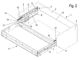
- FIGS. 1 to 4 a furniture body 1 can be seen, which has a carcass rear wall 2 and two opposing carcass cheeks 3.
- rail-guided thrust element 4 is slidably mounted, of which only a peripheral frame is shown and may be part of a drawer, register extension or the like.
- the thrust element 4 is mounted on two opposite rail systems on the furniture body 1, each of which consists of a firmly connected to the body panel 3 guide rail 8, a middle rail 7 and a running rail 6, with a side wall of the thrust element 4 is connected or may be an integral part and which are relatively movable.
- a synchronous guide 5 which has two immovably positioned on the furniture body 1 gears 9, which are connected via a transversely to the direction of displacement of the thrust element 4 extending coupling rod 10, wherein at each of the two ends the coupling rod 10 a gear 9 is secured against rotation.
- the gears 9 are arranged in the rear region of the furniture body 1 and stored in the present case in each case in a guide rail 12 which is fixed parallel to the guide rail 8 extending on the associated body panel 3.
- the drive belt 11 is guided stably in a guide slot 13 of the guide rail 12, that is, the height of the guide slot 13 is dimensioned so that a buckling of the drive belt 11 during insertion of the push element 4 is prevented.
- the drive belt 11 is guided, starting from the holder 16 in the guide slot 13 into a connection region with the gear 9, where it is continued under deflection by 180 ° in the laterally guided in parallel guide slot 13, in which the practically loose end of Drive belt 11 rests.
- a so-called over extension in which the thrust element 4 is positioned in the extended position in front of the front of the furniture body 1.
- a corresponding to the movement of the thrust element 4 displaceable guide extension 14 is mounted in the guide bar 12, which is displaced by a fixed to the holder 16 pressure member 17 from the guide bar 12 in an end position while at an insertion of the thrust element 4, the guide extension 14 by a connected tension spring 15, which is on the other hand secured to the guide rail 12, is retrieved.
- the drive belt 11 is made of a somewhat inherent stiff, but easily bendable material, for example, a suitable plastic or metal.
Landscapes
- Drawers Of Furniture (AREA)
- Transmission Devices (AREA)
Abstract
Description
- Die Erfindung betrifft eine Synchronführung eines in einem Möbelkorpus schienengeführten Schubelementes nach dem Oberbegriff des Anspruchs 1.
- Um ein gleichmäßiges Verschieben des Schubelementes zu gewährleisten, d.h., um vor allem beim Herausziehen des Schubelements aus dem Möbelkorpus Verwindungen und Verkantungen zu vermeiden, wie sie insbesondere bei breiten und/oder labilen Schubelementen auftreten können, kommen Synchronführungen zum Einsatz, durch die ein gleichmäßiger und paralleler Auszug des Schubelementes erreicht werden soll.
- Eine solche Synchronführung ist aus der
EP 1 810 596 A1 bekannt. Dabei ist das jeweilige Zahnrad Bestandteil eines Schienenpakets, bestehend aus einer an einer Korpuswange befestigten Auszugsschiene, einer darin verschiebbar gelagerten Mittelschiene sowie einer an der Mittelschiene verschieblich festgelegten Laufschiene, die am Schubelement angeschlossen ist. - Das zugeordnete Zahnrad ist mit der Mittelschiene fest verbunden, während ein gattungsgemäßer Treibriemen einerseits am Schubelement und andererseits an der Mittelschiene befestigt ist.
- Die beiden sich gegenüberliegenden, jeder Seitenwand des Schubelementes zugeordneten Zahnräder sind verdrehsicher an den beiden Enden einer drehbaren Koppelstange befestigt, über die die Bewegung des einen Zahnrades synchron auf das andere Zahnrad übertragen wird, wobei die eigentliche Drehbewegung der Zahnräder sich aus der linearen Relativbewegung des Schubelements zur Mittelschiene beim Verschieben des Schubelementes ergibt.
- Da das genannte Schienenpaket jeweils nur hinsichtlich seiner Länge für ein bestimmtes Schubelement einsetzbar ist, müssen für unterschiedlich tiefe Schubelemente auch entsprechend modifizierte Schienenpakete vorgehalten werden, mit integrierter Synchronführung.
- Neben diesem vor allem betriebswirtschaftlichen Nachteil ist weiter zu beklagen, dass die bekannte Synchronführung nicht nachträglich in ein mit Schubelementen bestücktes Möbel eingebaut werden kann. Im Bedarfsfall muss hier zumindest das komplette Schienenführungs-System ausgetauscht werden, wenn nicht gar einschließlich des Schubelementes.
- Der Erfindung liegt die Aufgabe zugrunde, eine Synchronführung der gattungsgemäßen Art so weiterzuentwickeln, dass ihre Verwendungsfähigkeit mit geringem konstruktiven und fertigungstechnischen Aufwand verbessert wird.
- Diese Aufgabe wird durch eine Synchronführung mit den Merkmalen des Anspruchs 1 gelöst. Gemäß der gestellten Aufgabe ist die neue Synchronführung für unterschiedlichste Abmessungen von Schubelementen verwendbar, da die Zahnräder nun nicht mehr integraler Bestandteil des Schienensystems sind, sondern unabhängig davon am Möbelkorpus befestigt werden.
- Dies erlaubt auch eine nachträgliche Ausrüstung des Möbels mit einer Synchronführung, was naturgemäß mit einer für diesen Fall erheblichen Kostenersparnis verbunden ist.
- Eine vorteilhafte Weiterbildung der Erfindung sieht vor, dass der jeweilige Treibriemen schubstabil geführt ist, wozu bevorzugt eine Führungsleiste an der zugeordneten Korpuswange befestigt sein kann, die einen Führungsschlitz aufweist, in dem der Treibriemen bei einem Einschieben des Schubelementes gegen ein Knicken gesichert geführt ist.
- Diese Führungsleiste dient zweckmäßigerweise auch der Lagerung des Zahnrades, mit dem der Treibriemen in Wirkverbindung steht. Dabei wird der Treibriemen im Bereich des Zahnrades vorzugsweise um 180° umgelenkt in Fortführung des Führungsschlitzes der Führungsleiste. Denkbar ist auch, den Treibriemen nach einer Umlenkung beispielsweise auf einer Rolle aufzuwickeln.
- Zur Verringerung der Reibung kann der Treibriemen mit einer geeigneten Beschichtung versehen sein, z.B. mit PTFE. Alternativ besteht auch die Möglichkeit, bei der Herstellung des Treibriemens ein solches Mittel als integralen Bestandteil mit einzubringen.
- Zur Vermeidung bzw. Minimierung von Geräuschen besteht der Treibriemen bevorzugt aus einem Verbundwerkstoff. Hierzu kann ein Kunststoff mit Fasereinlage vorgesehen sein oder ein Verbund aus einem Material hoher Festigkeit, wie Metall, mit einem flexiblen Kunststoff.
- Durch die schubstabile Führung des Treibriemens kann auf einen wie auch immer gearteten, an dem der Anbindung des Treibriemens am Schubelement abgewandten Ende festgelegten Mitnehmer verzichtet werden, durch den eine Straffung des Treibriemens beim Einschieben des Schubelementes erfolgen müsste.
- Darüber hinaus kann der Treibriemen sozusagen als handelsübliche Rollenware auf das jeweils erforderliche Maß abgelängt werden, was ebenfalls zu einer Kostenreduzierung beiträgt.
- Im Übrigen kann als Treibriemen jede geeignete Ausführungsvariante Verwendung finden. Beispielhaft seien hier ein Zahnriemen, eine Gliederkette oder ein Lochband genannt. Wesentlich ist, dass der Treibriemen, wie bereits aus dem Stand der Technik bekannt, formschlüssig mit dem Zahnrad in Eingriff steht.
- Statt der erwähnten Lagerung des jeweiligen Zahnrades in einer Führungsleiste, besteht selbstverständlich auch die Möglichkeit, das Zahnrad in einem separaten Halter zu lagern, der entweder an der Korpuswange oder an der Korpusrückwand des Möbels befestigt wird.
- Die Anbindung des Treibriemens am Schubelement erfolgt zweckmäßigerweise über eine Halterung, die bevorzugt an der Rückwand des Schubelementes befestigt ist.
- Als weiterer Vorteil der Erfindung ist zu erwähnen, dass durch die von den Auszugsschienen losgelöste Befestigung der Zahnräder im Zusammenspiel mit dem flexiblen Treibriemen ohne weiteres ein Ausgleich von relativ großen Fertigungstoleranzen des Möbelkorpus möglich ist, wie sie in der Möbelfertigung auftreten und akzeptiert werden. Daraus ergibt sich eine durchaus bemerkenswerte Verbesserung der Funktionssicherheit.
- Die ortsfest gelagerte Koppelstange kann zum Ein- und Ausfahren des Schubelementes mit einem Antrieb versehen sein. Denkbar ist auch, an die Koppelstange eine Selbsteinzugsvorrichtung, z.B. in Form einer Rollfeder anzuschließen, wobei die Einfahrbewegung des Schubelementes durch einen mit der Koppelstange in Verbindung stehenden Rotationsdämpfer gedämpft werden kann.
- Ein Ausstoßen des Schubelementes kann unter Zuhilfenahme bekannter Mechanismen, wie eines Kronenmechanismus, einer Herzkurve oder einer 3-D-Kurve oder einer Rollfeder erfolgen.
- Durch eine entsprechende Modifizierung der Synchronführung kann eine Auslaufsicherung für das Schubelement hergestellt werden.
- Weitere vorteilhafte Ausbildungen der Erfindung sind in den Unteransprüchen gekennzeichnet.
- Ein Ausführungsbeispiel der Erfindung wird nachfolgend anhand der beigefügten Zeichnungen beschrieben.
-
- Figuren 1 und 2
- ein mit einer erfindungsgemäßen Synchronführung versehenes Möbel in unterschiedlichen Funktionsstellungen, jeweils per-spektivisch dargestellt
- Figur 3 und 4
- das Möbel in den den
Figuren 1 und2 entsprechenden Funkti-onsstellungen unter Fortfall bestimmter Bauteile der Synchron-führung - Figur 5
- eine Einzelheit des Möbels in einer rückseitigen Ansicht, gleich-falls schaubildlich dargestellt.
- In den
Figuren 1 bis 4 ist ein Möbelkorpus 1 erkennbar, der eine Korpusrückwand 2 sowie zwei sich gegenüberliegende Korpuswangen 3 aufweist. - In dem Möbelkorpus 1 ist schienengeführt ein Schubelement 4 verschiebbar gelagert, von dem lediglich ein umlaufender Rahmen gezeigt ist und der Bestandteil eines Schubkastens, Registerauszugs oder dergleichen sein kann.
- Während in den
Figuren 1 und3 das Schubelement 4 in den Möbelkorpus 1 eingeschoben dargestellt ist, geben dieFiguren 2 und4 eine ausgezogene Stellung wieder. - Hier ist deutlich zu erkennen, dass das Schubelement 4 über zwei sich gegenüberliegende Schienensysteme am Möbelkorpus 1 gelagert ist, von denen jedes aus einer mit der Korpuswange 3 fest verbundenen Führungsschiene 8, einer Mittelschiene 7 sowie einer Laufschiene 6 besteht, die mit einer Seitenwand des Schubelementes 4 verbunden ist oder integraler Bestandteil sein kann und die relativ zueinander bewegbar sind.
- Für eine gleichmäßige, d.h. synchrone Verschiebung des Schubelementes 4 ist eine Synchronführung 5 vorgesehen, die zwei am Möbelkorpus 1 unverrückbar positionierte Zahnräder 9 aufweist, die über eine sich quer zur Verschieberichtung des Schubelementes 4 erstreckende Koppelstange 10 miteinander verbunden sind, wobei an jedem der beiden Enden der Koppelstange 10 ein Zahnrad 9 verdrehsicher befestigt ist.
- Die Zahnräder 9 sind im rückwärtigen Bereich des Möbelkorpus 1 angeordnet und im vorliegenden Fall jeweils in einer Führungsleiste 12 gelagert, die parallel zur Führungsschiene 8 verlaufend an der zugeordneten Korpuswange 3 festgelegt ist.
- Ein Treibriemen 11, der besonders deutlich in den
Figuren 3 und4 erkennbar ist, da hier auf die Darstellung der Führungsleiste 12 verzichtet ist, ist mit einem Ende am Schubelement 4 befestigt und zwar in einer Halterung 16, die an der Rückseite des Schubelementes 4 angeschlossen ist. - Der Treibriemen 11 ist in einem Führungsschlitz 13 der Führungsleiste 12 schubstabil geführt, d.h., die Höhe des Führungsschlitzes 13 ist so bemessen, dass ein Knicken des Treibriemens 11 beim Einschieben des Schubelementes 4 verhindert wird.
- Der Treibriemen 11 ist, ausgehend von der Halterung 16 in dem Führungsschlitz 13 bis in einen Verbindungsbereich mit dem Zahnrad 9 geführt, wo er unter Umlenkung um 180° in den im weiteren Verlauf parallel geführten Führungsschlitz 13 weitergeführt wird, in dem das praktisch lose Ende des Treibriemens 11 einliegt.
- Bei einem Ausziehen des Schubelementes 4 aus dem Möbelkorpus 1 wird demnach der Treibriemen 11 mitgezogen und gelangt so unter Umlenkung und Abstützung, bei gleichzeitiger Drehung des Zahnrades 9, mit dem der Treibriemen 11 in Eingriff steht, weitgehend aus dem in diesem Fall oberen Teil des Führungsschlitzes 13 in dessen dazu parallelen unteren Teil, wie in der
Figur 4 erkennbar ist. - Da durch die Linearbewegung der Treibriemen 11 die kämmenden Zahnräder 9 in Drehung versetzt und diese durch die Koppelstange 10 verdrehsicher zueinander verbunden sind, ist der Bewegungsablauf sowohl der Treibriemen 11 wie auch der Zahnräder 9 synchron und damit die Auszugsbewegung des Schubelementes 4 insgesamt.
- Erkennbar handelt es sich im Ausführungsbeispiel um einen sogenannten Überauszug, bei dem das Schubelement 4 in ausgezogener Stellung vor der Vorderseite des Möbelkorpus 1 positioniert ist. Um dem an der Halterung 16 befestigten Treibriemen 11 über das vordere Ende des Führungsschlitzes 13 hinaus eine Führung zu geben, ist in der Führungsleiste 12 eine entsprechend der Verfahrbewegung des Schubelementes 4 verschiebbare Führungsverlängerung 14 gelagert, die durch ein an der Halterung 16 befestigtes Druckstück 17 aus der Führungsleiste 12 in eine Endstellung verschoben wird, während bei einem Einschieben des Schubelementes 4 die Führungsverlängerung 14 durch eine angeschlossene Zugfeder 15, die andererseits an der Führungsleiste 12 befestigt ist, zurückgeholt wird.
- Der Treibriemen 11 ist aus einem in gewissem Maße eigensteifen, jedoch problemlos biegsamen Material hergestellt, beispielsweise einem geeigneten Kunststoff oder Metall.
- Bezugszeichenliste
- 1
- Möbelkorpus
- 2
- Korpusrückwand
- 3
- Korpuswange
- 4
- Schubelement
- 5
- Synchronführung
- 6
- Laufschiene
- 7
- Mittelschiene
- 8
- Führungsschiene
- 9
- Zahnrad
- 10
- Koppelstange
- 11
- Treibriemen
- 12
- Führungsleiste
- 13
- Führungsschlitz
- 14
- Führungsverlängerung
- 15
- Zugfeder
- 16
- Halterung
- 17
- Druckstück
Claims (12)
- Synchronführung eines in einem Möbelkorpus (1) gelagerten Schubelementes (4), mit zwei an den Enden einer drehbaren, quer zur Verschieberichtung des Schubelementes (4) verlaufenden Koppelstange (10) verdrehsicher gehaltenen Zahnrädern (9), in die jeweils ein am Schubelement (4) angeschlossener Treibriemen (11) eingreift, dadurch gekennzeichnet, dass die Zahnräder (9) im rückwärtigen Bereich des Möbelkorpus (1) fest positioniert sind.
- Synchronführung nach Anspruch 1, dadurch gekennzeichnet, dass der Treibriemen (11) schubstabil geführt ist.
- Synchronführung nach Anspruch 1 oder 2, dadurch gekennzeichnet, dass der Treibriemen (11) in einem Führungsschlitz (13) einer Führungsleiste (12) verschiebbar geführt ist, die an einer zugeordneten Korpuswange (3) befestigt ist.
- Synchronführung nach einem der vorhergehenden Ansprüche, dadurch gekennzeichnet, dass die Zahnräder (9) in der jeweiligen Führungsleiste (12) drehbar gelagert sind.
- Synchronführung nach einem der vorhergehenden Ansprüche, dadurch gekennzeichnet, dass der Treibriemen (11) im Eingriffsbereich mit dem Zahnrad (9) abgestützt ist.
- Synchronführung nach einem der vorhergehenden Ansprüche, dadurch gekennzeichnet, dass der Treibriemen (11) mit seinem dem Schubelement (4) abgewandten Ende frei in dem Führungsschlitz (13) einliegt.
- Synchronführung nach einem der vorhergehenden Ansprüche, dadurch gekennzeichnet, dass der Treibriemen (11) an einer mit dem Schubelement (4) fest verbundenen Halterung (16) angeschlossen ist.
- Synchronführung nach einem der vorhergehenden Ansprüche, dadurch gekennzeichnet, dass die Führungsleiste (12) in Verlängerung des Führungsschlitzes (13) zur weiteren Führung des Treibriemens (11) bei einem Überauszug eine verschiebbar gelagerte Führungsverlängerung (14) aufweist.
- Synchronführung nach einem der vorhergehenden Ansprüche, dadurch gekennzeichnet, dass die Führungsverlängerung (14) federbelastet aus der Führungsleiste (12) herausschiebbar ist.
- Synchronführung nach einem der vorhergehenden Ansprüche, dadurch gekennzeichnet, dass an der Führungsverlängerung (14) eine Zugfeder (15) befestigt ist, die andererseits an der Führungsleiste (12) angeschlossen ist.
- Synchronführung nach einem der vorhergehenden Ansprüche, dadurch gekennzeichnet, dass die Halterung (16) ein Druckstück (17) aufweist, zum Herausschieben der Führungsverlängerung (14) aus der Führungsleiste (12).
- Synchronführung nach einem der vorhergehenden Ansprüche, dadurch gekennzeichnet, dass der Treibriemen (11) als Zahnriemen, Lochband oder Kette ausgebildet ist.
Applications Claiming Priority (1)
| Application Number | Priority Date | Filing Date | Title |
|---|---|---|---|
| DE202008012100U DE202008012100U1 (de) | 2008-09-12 | 2008-09-12 | Synchronführung eines Schubelements |
Publications (2)
| Publication Number | Publication Date |
|---|---|
| EP2165624A1 true EP2165624A1 (de) | 2010-03-24 |
| EP2165624B1 EP2165624B1 (de) | 2013-01-30 |
Family
ID=41381685
Family Applications (1)
| Application Number | Title | Priority Date | Filing Date |
|---|---|---|---|
| EP09169716A Active EP2165624B1 (de) | 2008-09-12 | 2009-09-08 | Synchronführung eines Schubladens |
Country Status (3)
| Country | Link |
|---|---|
| EP (1) | EP2165624B1 (de) |
| DE (1) | DE202008012100U1 (de) |
| ES (1) | ES2405553T3 (de) |
Cited By (1)
| Publication number | Priority date | Publication date | Assignee | Title |
|---|---|---|---|---|
| DE102013113672A1 (de) | 2013-06-14 | 2014-12-18 | Paul Hettich Gmbh & Co. Kg | Auszugssystem |
Families Citing this family (1)
| Publication number | Priority date | Publication date | Assignee | Title |
|---|---|---|---|---|
| CN108916226B (zh) * | 2018-08-24 | 2023-08-18 | 无锡海达尔精密滑轨股份有限公司 | 三节式同步滑轨 |
Citations (3)
| Publication number | Priority date | Publication date | Assignee | Title |
|---|---|---|---|---|
| DE202004016393U1 (de) * | 2004-10-21 | 2005-12-29 | Grass Gmbh | Vorrichtung zur Stabilisierung des Laufverhaltens eines in einem Möbelkorpus fahrbaren Möbelteiles |
| EP1810596A1 (de) | 2006-01-18 | 2007-07-25 | Anton Schneider Gmbh & Co. | Differentialauszug für Schubladen oder dergleichen |
| DE202006004699U1 (de) * | 2006-03-22 | 2007-08-02 | Grass Gmbh | Vorrichtung zum Bewegen eines ersten Möbelteils relativ zu einem zweiten Möbelteil |
Family Cites Families (5)
| Publication number | Priority date | Publication date | Assignee | Title |
|---|---|---|---|---|
| DE4227844C2 (de) * | 1992-08-22 | 1998-10-22 | Fortschritt Gmbh | Höhenverstellvorrichtung für Arbeitsplatten |
| DE10322795B3 (de) * | 2003-05-19 | 2004-12-16 | Stanzwerk Wetter Sichelschmidt Gmbh & Co. Kg | Sitzmöbel mit ausschwenkbarer Fußstütze |
| DE202006012283U1 (de) * | 2006-08-09 | 2007-12-13 | Grass Gmbh | Vorrichtung zum Bewegen eines ersten Möbelteils relativ zu einem zweiten Möbelteil und Möbel |
| AT504375B1 (de) * | 2006-10-23 | 2010-01-15 | Blum Gmbh Julius | Möbel mit einer antriebsvorrichtung für bewegbare möbelteile |
| DE202007015230U1 (de) * | 2007-11-02 | 2008-02-28 | Herbach, Burkhard | Antriebsanordnung eines beweglichen Möbelteils |
-
2008
- 2008-09-12 DE DE202008012100U patent/DE202008012100U1/de not_active Expired - Lifetime
-
2009
- 2009-09-08 ES ES09169716T patent/ES2405553T3/es active Active
- 2009-09-08 EP EP09169716A patent/EP2165624B1/de active Active
Patent Citations (3)
| Publication number | Priority date | Publication date | Assignee | Title |
|---|---|---|---|---|
| DE202004016393U1 (de) * | 2004-10-21 | 2005-12-29 | Grass Gmbh | Vorrichtung zur Stabilisierung des Laufverhaltens eines in einem Möbelkorpus fahrbaren Möbelteiles |
| EP1810596A1 (de) | 2006-01-18 | 2007-07-25 | Anton Schneider Gmbh & Co. | Differentialauszug für Schubladen oder dergleichen |
| DE202006004699U1 (de) * | 2006-03-22 | 2007-08-02 | Grass Gmbh | Vorrichtung zum Bewegen eines ersten Möbelteils relativ zu einem zweiten Möbelteil |
Cited By (1)
| Publication number | Priority date | Publication date | Assignee | Title |
|---|---|---|---|---|
| DE102013113672A1 (de) | 2013-06-14 | 2014-12-18 | Paul Hettich Gmbh & Co. Kg | Auszugssystem |
Also Published As
| Publication number | Publication date |
|---|---|
| EP2165624B1 (de) | 2013-01-30 |
| ES2405553T3 (es) | 2013-05-31 |
| DE202008012100U1 (de) | 2010-02-11 |
Similar Documents
| Publication | Publication Date | Title |
|---|---|---|
| AT509923B1 (de) | Einzugsvorrichtung zum einziehen eines bewegbar gelagerten möbelteiles | |
| EP2770876B1 (de) | Synchronisierte verriegelung für ein bewegbares möbelteil | |
| EP1120065B1 (de) | Ausziehführungsgarnitur für Schubladen | |
| EP2538818B1 (de) | Ausziehführung für schubladen | |
| EP1921948B1 (de) | Verriegelbare ausstossvorrichtung | |
| EP2144531B1 (de) | Ausziehführung für schubladen | |
| EP3084107B1 (de) | Auszugsführung für ein schiebeelement | |
| EP3694375B1 (de) | Einzugsvorrichtung und verfahren zum öffnen und schliessen eines bewegbaren möbelteils | |
| EP1959792B1 (de) | Möbel mit wenigstens einem ersten und einem zweiten möbelteil | |
| EP2210525B1 (de) | Schließsystem eines ausziehbaren Möbelteils und Möbel | |
| EP2186437A2 (de) | Synchronführung eines Schubelementes | |
| EP2636340B1 (de) | Führungseinrichtung zur Führung eines relativ zu einem Möbelkorpus bewegbaren Möbelteils | |
| DE202008015848U1 (de) | Synchronführung eines Schubelementes | |
| EP1743550B1 (de) | Verschiebungsautomatik für Möbelauszüge, insbesondere Schubladen | |
| EP2464258B1 (de) | Ein- oder auszugsvorrichtung zum bewegen eines bewegbaren möbelteiles | |
| EP2165624B1 (de) | Synchronführung eines Schubladens | |
| DE102010038247A1 (de) | Schließsystem eines ausziehbaren Möbelteils und Möbel | |
| DE2713693A1 (de) | Verstellvorrichtung fuer sitze, insbesondere kraftfahrzeugsitze | |
| EP4385363A2 (de) | Anordnung mit antriebsvorrichtung und synchronisierungsvorrichtung für ausziehführungen für eine schublade | |
| EP3434144B1 (de) | Ausziehführung | |
| DE20319598U1 (de) | Einzugsautomatik für Schubladen-Ausziehführungen | |
| EP2827742B1 (de) | Möbelauszug | |
| EP1591317B1 (de) | Staufachabdeckung | |
| DE102012215433B4 (de) | Rollosystem für einen Fahrzeuginnenraum | |
| EP2191753A1 (de) | Getränkeautomat |
Legal Events
| Date | Code | Title | Description |
|---|---|---|---|
| PUAI | Public reference made under article 153(3) epc to a published international application that has entered the european phase |
Free format text: ORIGINAL CODE: 0009012 |
|
| AK | Designated contracting states |
Kind code of ref document: A1 Designated state(s): AT BE BG CH CY CZ DE DK EE ES FI FR GB GR HR HU IE IS IT LI LT LU LV MC MK MT NL NO PL PT RO SE SI SK SM TR |
|
| AX | Request for extension of the european patent |
Extension state: AL BA RS |
|
| 17P | Request for examination filed |
Effective date: 20100622 |
|
| 17Q | First examination report despatched |
Effective date: 20100720 |
|
| GRAP | Despatch of communication of intention to grant a patent |
Free format text: ORIGINAL CODE: EPIDOSNIGR1 |
|
| GRAS | Grant fee paid |
Free format text: ORIGINAL CODE: EPIDOSNIGR3 |
|
| GRAA | (expected) grant |
Free format text: ORIGINAL CODE: 0009210 |
|
| AK | Designated contracting states |
Kind code of ref document: B1 Designated state(s): AT BE BG CH CY CZ DE DK EE ES FI FR GB GR HR HU IE IS IT LI LT LU LV MC MK MT NL NO PL PT RO SE SI SK SM TR |
|
| REG | Reference to a national code |
Ref country code: GB Ref legal event code: FG4D Free format text: NOT ENGLISH |
|
| REG | Reference to a national code |
Ref country code: CH Ref legal event code: EP |
|
| REG | Reference to a national code |
Ref country code: AT Ref legal event code: REF Ref document number: 595542 Country of ref document: AT Kind code of ref document: T Effective date: 20130215 Ref country code: CH Ref legal event code: EP |
|
| REG | Reference to a national code |
Ref country code: IE Ref legal event code: FG4D Free format text: LANGUAGE OF EP DOCUMENT: GERMAN |
|
| REG | Reference to a national code |
Ref country code: DE Ref legal event code: R096 Ref document number: 502009006146 Country of ref document: DE Effective date: 20130328 |
|
| REG | Reference to a national code |
Ref country code: ES Ref legal event code: FG2A Ref document number: 2405553 Country of ref document: ES Kind code of ref document: T3 Effective date: 20130531 |
|
| REG | Reference to a national code |
Ref country code: LT Ref legal event code: MG4D |
|
| REG | Reference to a national code |
Ref country code: NL Ref legal event code: VDEP Effective date: 20130130 |
|
| PG25 | Lapsed in a contracting state [announced via postgrant information from national office to epo] |
Ref country code: IS Free format text: LAPSE BECAUSE OF FAILURE TO SUBMIT A TRANSLATION OF THE DESCRIPTION OR TO PAY THE FEE WITHIN THE PRESCRIBED TIME-LIMIT Effective date: 20130530 Ref country code: SE Free format text: LAPSE BECAUSE OF FAILURE TO SUBMIT A TRANSLATION OF THE DESCRIPTION OR TO PAY THE FEE WITHIN THE PRESCRIBED TIME-LIMIT Effective date: 20130130 Ref country code: NO Free format text: LAPSE BECAUSE OF FAILURE TO SUBMIT A TRANSLATION OF THE DESCRIPTION OR TO PAY THE FEE WITHIN THE PRESCRIBED TIME-LIMIT Effective date: 20130430 Ref country code: LT Free format text: LAPSE BECAUSE OF FAILURE TO SUBMIT A TRANSLATION OF THE DESCRIPTION OR TO PAY THE FEE WITHIN THE PRESCRIBED TIME-LIMIT Effective date: 20130130 Ref country code: BG Free format text: LAPSE BECAUSE OF FAILURE TO SUBMIT A TRANSLATION OF THE DESCRIPTION OR TO PAY THE FEE WITHIN THE PRESCRIBED TIME-LIMIT Effective date: 20130430 |
|
| PG25 | Lapsed in a contracting state [announced via postgrant information from national office to epo] |
Ref country code: FI Free format text: LAPSE BECAUSE OF FAILURE TO SUBMIT A TRANSLATION OF THE DESCRIPTION OR TO PAY THE FEE WITHIN THE PRESCRIBED TIME-LIMIT Effective date: 20130130 Ref country code: GR Free format text: LAPSE BECAUSE OF FAILURE TO SUBMIT A TRANSLATION OF THE DESCRIPTION OR TO PAY THE FEE WITHIN THE PRESCRIBED TIME-LIMIT Effective date: 20130501 Ref country code: LV Free format text: LAPSE BECAUSE OF FAILURE TO SUBMIT A TRANSLATION OF THE DESCRIPTION OR TO PAY THE FEE WITHIN THE PRESCRIBED TIME-LIMIT Effective date: 20130130 Ref country code: SI Free format text: LAPSE BECAUSE OF FAILURE TO SUBMIT A TRANSLATION OF THE DESCRIPTION OR TO PAY THE FEE WITHIN THE PRESCRIBED TIME-LIMIT Effective date: 20130130 Ref country code: NL Free format text: LAPSE BECAUSE OF FAILURE TO SUBMIT A TRANSLATION OF THE DESCRIPTION OR TO PAY THE FEE WITHIN THE PRESCRIBED TIME-LIMIT Effective date: 20130130 Ref country code: PL Free format text: LAPSE BECAUSE OF FAILURE TO SUBMIT A TRANSLATION OF THE DESCRIPTION OR TO PAY THE FEE WITHIN THE PRESCRIBED TIME-LIMIT Effective date: 20130130 Ref country code: PT Free format text: LAPSE BECAUSE OF FAILURE TO SUBMIT A TRANSLATION OF THE DESCRIPTION OR TO PAY THE FEE WITHIN THE PRESCRIBED TIME-LIMIT Effective date: 20130530 |
|
| PG25 | Lapsed in a contracting state [announced via postgrant information from national office to epo] |
Ref country code: HR Free format text: LAPSE BECAUSE OF FAILURE TO SUBMIT A TRANSLATION OF THE DESCRIPTION OR TO PAY THE FEE WITHIN THE PRESCRIBED TIME-LIMIT Effective date: 20130130 |
|
| PG25 | Lapsed in a contracting state [announced via postgrant information from national office to epo] |
Ref country code: DK Free format text: LAPSE BECAUSE OF FAILURE TO SUBMIT A TRANSLATION OF THE DESCRIPTION OR TO PAY THE FEE WITHIN THE PRESCRIBED TIME-LIMIT Effective date: 20130130 Ref country code: SK Free format text: LAPSE BECAUSE OF FAILURE TO SUBMIT A TRANSLATION OF THE DESCRIPTION OR TO PAY THE FEE WITHIN THE PRESCRIBED TIME-LIMIT Effective date: 20130130 Ref country code: EE Free format text: LAPSE BECAUSE OF FAILURE TO SUBMIT A TRANSLATION OF THE DESCRIPTION OR TO PAY THE FEE WITHIN THE PRESCRIBED TIME-LIMIT Effective date: 20130130 Ref country code: RO Free format text: LAPSE BECAUSE OF FAILURE TO SUBMIT A TRANSLATION OF THE DESCRIPTION OR TO PAY THE FEE WITHIN THE PRESCRIBED TIME-LIMIT Effective date: 20130130 Ref country code: CZ Free format text: LAPSE BECAUSE OF FAILURE TO SUBMIT A TRANSLATION OF THE DESCRIPTION OR TO PAY THE FEE WITHIN THE PRESCRIBED TIME-LIMIT Effective date: 20130130 |
|
| PGFP | Annual fee paid to national office [announced via postgrant information from national office to epo] |
Ref country code: ES Payment date: 20130923 Year of fee payment: 5 |
|
| PG25 | Lapsed in a contracting state [announced via postgrant information from national office to epo] |
Ref country code: CY Free format text: LAPSE BECAUSE OF FAILURE TO SUBMIT A TRANSLATION OF THE DESCRIPTION OR TO PAY THE FEE WITHIN THE PRESCRIBED TIME-LIMIT Effective date: 20130130 |
|
| PGFP | Annual fee paid to national office [announced via postgrant information from national office to epo] |
Ref country code: GB Payment date: 20130920 Year of fee payment: 5 Ref country code: TR Payment date: 20130828 Year of fee payment: 5 |
|
| PLBE | No opposition filed within time limit |
Free format text: ORIGINAL CODE: 0009261 |
|
| STAA | Information on the status of an ep patent application or granted ep patent |
Free format text: STATUS: NO OPPOSITION FILED WITHIN TIME LIMIT |
|
| PGFP | Annual fee paid to national office [announced via postgrant information from national office to epo] |
Ref country code: IT Payment date: 20130924 Year of fee payment: 5 |
|
| 26N | No opposition filed |
Effective date: 20131031 |
|
| PGFP | Annual fee paid to national office [announced via postgrant information from national office to epo] |
Ref country code: FR Payment date: 20130918 Year of fee payment: 5 |
|
| REG | Reference to a national code |
Ref country code: DE Ref legal event code: R097 Ref document number: 502009006146 Country of ref document: DE Effective date: 20131031 |
|
| BERE | Be: lapsed |
Owner name: PAUL HETTICH G.M.B.H. & CO. KG Effective date: 20130930 |
|
| PG25 | Lapsed in a contracting state [announced via postgrant information from national office to epo] |
Ref country code: MC Free format text: LAPSE BECAUSE OF FAILURE TO SUBMIT A TRANSLATION OF THE DESCRIPTION OR TO PAY THE FEE WITHIN THE PRESCRIBED TIME-LIMIT Effective date: 20130130 |
|
| REG | Reference to a national code |
Ref country code: CH Ref legal event code: PL |
|
| REG | Reference to a national code |
Ref country code: IE Ref legal event code: MM4A |
|
| PG25 | Lapsed in a contracting state [announced via postgrant information from national office to epo] |
Ref country code: CH Free format text: LAPSE BECAUSE OF NON-PAYMENT OF DUE FEES Effective date: 20130930 Ref country code: LI Free format text: LAPSE BECAUSE OF NON-PAYMENT OF DUE FEES Effective date: 20130930 Ref country code: BE Free format text: LAPSE BECAUSE OF NON-PAYMENT OF DUE FEES Effective date: 20130930 Ref country code: IE Free format text: LAPSE BECAUSE OF NON-PAYMENT OF DUE FEES Effective date: 20130908 |
|
| GBPC | Gb: european patent ceased through non-payment of renewal fee |
Effective date: 20140908 |
|
| PG25 | Lapsed in a contracting state [announced via postgrant information from national office to epo] |
Ref country code: SM Free format text: LAPSE BECAUSE OF FAILURE TO SUBMIT A TRANSLATION OF THE DESCRIPTION OR TO PAY THE FEE WITHIN THE PRESCRIBED TIME-LIMIT Effective date: 20130130 |
|
| REG | Reference to a national code |
Ref country code: FR Ref legal event code: ST Effective date: 20150529 |
|
| PG25 | Lapsed in a contracting state [announced via postgrant information from national office to epo] |
Ref country code: MT Free format text: LAPSE BECAUSE OF FAILURE TO SUBMIT A TRANSLATION OF THE DESCRIPTION OR TO PAY THE FEE WITHIN THE PRESCRIBED TIME-LIMIT Effective date: 20130130 |
|
| PG25 | Lapsed in a contracting state [announced via postgrant information from national office to epo] |
Ref country code: LU Free format text: LAPSE BECAUSE OF NON-PAYMENT OF DUE FEES Effective date: 20130908 Ref country code: MK Free format text: LAPSE BECAUSE OF FAILURE TO SUBMIT A TRANSLATION OF THE DESCRIPTION OR TO PAY THE FEE WITHIN THE PRESCRIBED TIME-LIMIT Effective date: 20130130 Ref country code: HU Free format text: LAPSE BECAUSE OF FAILURE TO SUBMIT A TRANSLATION OF THE DESCRIPTION OR TO PAY THE FEE WITHIN THE PRESCRIBED TIME-LIMIT; INVALID AB INITIO Effective date: 20090908 Ref country code: GB Free format text: LAPSE BECAUSE OF NON-PAYMENT OF DUE FEES Effective date: 20140908 |
|
| PG25 | Lapsed in a contracting state [announced via postgrant information from national office to epo] |
Ref country code: IT Free format text: LAPSE BECAUSE OF NON-PAYMENT OF DUE FEES Effective date: 20140908 Ref country code: FR Free format text: LAPSE BECAUSE OF NON-PAYMENT OF DUE FEES Effective date: 20140930 |
|
| REG | Reference to a national code |
Ref country code: ES Ref legal event code: FD2A Effective date: 20151026 |
|
| REG | Reference to a national code |
Ref country code: AT Ref legal event code: MM01 Ref document number: 595542 Country of ref document: AT Kind code of ref document: T Effective date: 20140908 |
|
| PG25 | Lapsed in a contracting state [announced via postgrant information from national office to epo] |
Ref country code: AT Free format text: LAPSE BECAUSE OF NON-PAYMENT OF DUE FEES Effective date: 20140908 Ref country code: ES Free format text: LAPSE BECAUSE OF NON-PAYMENT OF DUE FEES Effective date: 20140909 |
|
| REG | Reference to a national code |
Ref country code: DE Ref legal event code: R079 Ref document number: 502009006146 Country of ref document: DE Free format text: PREVIOUS MAIN CLASS: A47B0088040000 Ipc: A47B0088400000 |
|
| PG25 | Lapsed in a contracting state [announced via postgrant information from national office to epo] |
Ref country code: TR Free format text: LAPSE BECAUSE OF NON-PAYMENT OF DUE FEES Effective date: 20140908 |
|
| REG | Reference to a national code |
Ref country code: DE Ref legal event code: R084 Ref document number: 502009006146 Country of ref document: DE |
|
| P01 | Opt-out of the competence of the unified patent court (upc) registered |
Effective date: 20230413 |
|
| PGFP | Annual fee paid to national office [announced via postgrant information from national office to epo] |
Ref country code: DE Payment date: 20250919 Year of fee payment: 17 |