EP2164768B1 - Schnalle und Befestigungsband mit einer solchen Schnalle - Google Patents
Schnalle und Befestigungsband mit einer solchen Schnalle Download PDFInfo
- Publication number
- EP2164768B1 EP2164768B1 EP08762483.9A EP08762483A EP2164768B1 EP 2164768 B1 EP2164768 B1 EP 2164768B1 EP 08762483 A EP08762483 A EP 08762483A EP 2164768 B1 EP2164768 B1 EP 2164768B1
- Authority
- EP
- European Patent Office
- Prior art keywords
- band
- buckle
- jaw
- teeth
- nylon
- Prior art date
- Legal status (The legal status is an assumption and is not a legal conclusion. Google has not performed a legal analysis and makes no representation as to the accuracy of the status listed.)
- Active
Links
Images


Classifications
-
- B—PERFORMING OPERATIONS; TRANSPORTING
- B65—CONVEYING; PACKING; STORING; HANDLING THIN OR FILAMENTARY MATERIAL
- B65D—CONTAINERS FOR STORAGE OR TRANSPORT OF ARTICLES OR MATERIALS, e.g. BAGS, BARRELS, BOTTLES, BOXES, CANS, CARTONS, CRATES, DRUMS, JARS, TANKS, HOPPERS, FORWARDING CONTAINERS; ACCESSORIES, CLOSURES, OR FITTINGS THEREFOR; PACKAGING ELEMENTS; PACKAGES
- B65D63/00—Flexible elongated elements, e.g. straps, for bundling or supporting articles
- B65D63/10—Non-metallic straps, tapes, or bands; Filamentary elements, e.g. strings, threads or wires; Joints between ends thereof
- B65D63/1018—Joints produced by application of integral securing members, e.g. buckles, wedges, tongue and slot, locking head and teeth or the like
- B65D63/1027—Joints produced by application of integral securing members, e.g. buckles, wedges, tongue and slot, locking head and teeth or the like the integral securing member being formed as a female and male locking member, e.g. locking head and locking teeth, or the like
Definitions
- the present invention relates to a fastener of the type comprising a band and a buckle for securing the band in a closed loop around one or more objects. At least one end of the band is secured in the buckle by means of teeth provided on the band and in the buckle; the two sets of teeth inter-engage to hold the band, as mentioned.
- the present invention is especially concerned with a fastener that compresses or clamps the article or articles encircled by the band, that is to say the band is under tension in use.
- Fasteners having a buckle and a band that can be formed into a closed loop, with at least one end of the band being held by teeth within the buckle are well known, for example UK Patent No. 1,600,601 .
- the buckle includes a pair of jaws, each having inwardly-facing teeth, which engage with teeth on the top and bottom surfaces of the band.
- Simple cable ties include toothed band and a passage formed at one end of the band that includes a toothed jaw projecting into the passage; the band is formed into a closed loop and one end is fed into the passage where the band teeth engage with the jaw teeth to maintain the band in the closed loop.
- WO2006/040524 describes a fastener comprising a toothed band and a buckle for holding the band in a closed loop.
- the buckle has a pair of opposed passageways that each include teeth arranged to engage the teeth on respective ends of the band and hold the ends of the band in their respective passageways, thereby maintaining the band is a closed loop that can compress one or more articles within the looped band.
- Clamps, ties and fasteners of the above type having a band and a fastening buckle can be made by injection moulding and either the band and the fastening buckle are formed as a single integral moulding or the band and the fastening buckle are formed separately as individual mouldings.
- the present invention provides a buckle that together with a band forms a fastener that can be made stronger than prior art fastener.
- US2006/0170559 describes a security tag for bottles that is secured around the bottle neck to prevent the tag being removed.
- the tag has an enclosed housing and a toothed band having two ends, one of which is fixed to the housing; the band is passed around the bottle neck and the other end of the band is fed into an opening in the housing where it engages with a ferromagnetic metal pawl to prevent it being pulled out.
- the pawl is attracted to the magnet and disengages from the toothed band, thereby allowing the free end of the band to be released from the housing and the tag removed.
- Such a mechanism would not work in a clamp since the tension in the band would cause the teeth and the pawl to engage tightly and so prevent the magnetic withdrawal of the ferromagnetic pawl.
- US-5230541 discloses a device that encircles a pair of cabinet handles to keep them together and so prevents the cabinet from being opened by a child.
- the device includes a housing and a band.
- One end section has a latch that is specially shaped to be engaged with an opening in the housing while the second end section of the band has teeth.
- the band is formed into a loop and the second end is engaged within a different opening in the housing by a pawl.
- the pawl is biased towards the teeth of the band and so stops the band being pulled back out of the opening, while allowing the band to be pulled further into the housing.
- the pawl can be disengaged from the teeth by inserting a screwdriver into a slot to engage the pawl and retract it from the teeth in the band.
- the band is made of nylon, the housing from ABS plastic and the pawl is made of CELCON (RTM) acetal resin.
- WO92/06606 discloses a buckle for use with a band according to the preamble of claim 1.
- the buckle comprises a lock mechanism for interconnecting two flat band end portions having a lock housing mechanism at the free end thereof.
- the lock housing a passageway for guiding the other band end portion through the mechanism.
- the other of said band end portions has incremental engageable means.
- the guide housing having flexible arresting means for engaging the incremental engageable means.
- the mechanism also has finger actuable release means to disengage the arresting means from the engageable means.
- US-4882813 discloses a banding clip for holding an article with an elongated band having a plurality of teeth.
- the clip comprising: first and second side walls spaced apart and extending substantially parallel to each other; first band engaging means for engaging one end portion of the band.
- the first band engaging means having a first base portion which extends between the walls.
- the clip also comprises first guiding means for guiding an end portion of the band into engagement with the first band engaging means.
- the first guiding means comprises at least one projection which projects from at least one of said walls.
- the clip further comprises a second band engaging means for engaging any portion other than said one end portion of the band.
- the second band engaging means has a second base portion which extends between the walls.
- the clip further comprises second guiding means for guiding any portion of the band into engagement with the second band engaging means.
- the second guiding means comprises at least one projection which projects from at least one of the walls.
- GB-2229491 discloses a tie assembly having a fixing block and a flexible strap. One end of which is anchored relative to the block.
- the block has a passage therethrough for reception of a length of the strap intermediate its free and anchored ends and at least one inwardly directed projection presenting a knife edge directed towards one end of the passage. The edge penetrates into a strap located within the passage.
- the present invention provides a buckle according to claim 1.
- the present invention provides also a fastener according to claim 13 having a buckle and a toothed band, which (a) can be kept in a closed loop and (b) can be held under tension by teeth in the buckle that engage corresponding teeth on the band; the teeth in the buckle are made of a different material as compared to the rest of the buckle and so can be made of a stronger and/or stiffer material that can resist forces resulting from tension in the band.
- the rest of the buckle to be made of a flexible, more ductile material, which is suitable for its role as part of the fastener, while making the jaw teeth of stiffer, less ductile material that can withstand higher forces on them before they deform which can result in the fastener failing; such forces are exerted on the jaw teeth by the teeth on the band, which in turn result from the tension in the band and the deformation of the teeth in the buckle can result in them loosing their engagement with the teeth on the band and hence the fastener failing.
- a biasing means is provided behind the teeth that forces the teeth down onto the band and makes for a reliable connection between the band teeth and the buckle teeth upon fitting.
- the fastener of the present invention eliminates the need for an integral mechanical hinge which is present in known designs where the body and the jaw of the buckle are formed as a single moulding.
- the hinge allows the jaw to pivot towards and away from the band and can bias the jaw towards the band. This hinge can break if the moulding material is too stiff; on the other hand if the moulding material is not stiff enough, the teeth on the jaw can deform and release the band under the influence of tension in the band.
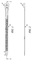
- Figures 1 to 3 are, respectively, a plan view, a side elevational view and a cross sectional view (taken along the axis A-A shown in Figure 1 ) of a buckle of the first embodiment of the present invention
- a fastener in the form of a tie, which includes a band 10 and a buckle 12 that are injection moulded as a single piece.
- the upper surface of the band carries a series of parallel teeth 11.
- the band 10 is flexible and can be formed into a closed loop to bundle together two or more articles within the closed loop or to compress one or more articles within the loop.
- the closure of the loop is achieved by taking the end 14 of the band and feeding it into a passage 15 though an opening 16 and pushing the band end out through exit 16'.
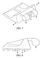
- a chamber 18 is provided, the top of which is open.
- a toothed jaw can be secured within the chamber 18 so that the teeth on the jaw engage with the teeth 11 on the outer surface of the looped band 10.
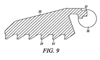
- the jaw 20 has a lower surface 22 that includes a set of teeth 24 that are configured to engage with the teeth 11 on the band 10.
- the jaw 20 is held within the chamber 18 by means of a hinge connection that includes a pair of trunnions 26 that are separated by a ledge 27.
- the buckle 12 includes a pair of recesses 28, each having a circular base that can accommodate the trunnions 26.
- an L-shaped resilient element 30 having a short leg 31, which is spaced above a part of the buckle 32 by a gap 34 (see Figure 5 ). Resilience in the longer leg 35 of the L- shaped element allows the resilient element 30 to be moved backwards.
- the jaw can be fitted within the buckle by pulling the L-shaped resilient element 30 backwards (see Figure 5 ) to open the gap 34 and allow the ledge 27 of the jaw to locate under the shorter leg 31 and for the trunnions 26 to be located within the recesses 28.
- the resilient element 30 is released, the jaw is held captive by the above arrangement. However, it can be released by reversing the above-described operation.
- the trunnions 26 are located within the recesses 28 while the ledge 27 is engaged in the gap 34 between the resilient member 30 and the buckle part 32 with the top surface of the ledge 27 being engaged under the short leg 31 of the resilient element 30.
- the jaw 20 can pivot upwardly and downwardly within the chamber about the trunnions 26 to bring the teeth 24 on the jaw into and out of engagement with the teeth 11 in the band 10, when the band is located in the passage 15.
- Such upward pivoting motion causes the ledge 27 to press against the resilient element 30 and move it backwards; the resilience in the element 30 resists the upward movement of the jaw and accordingly keeps the jaw 20 in engagement with the band 10 to maintain the band in a closed loop.
- the shape of the teeth is such that, when tension is applied to the band, the jaw is urged towards the band.
- the end 14 is passed through the opening 16 in the passage 15 of the buckle and out through the other end 16 of the passage.
- the jaw 20 pivotally held within the chamber 18 engages the band and prevents it from being moved backwards through the passage 15.
- the back surfaces 40 of the teeth 24 of the jaw are sloped to allow the band end 14 to be moved from end 16 to end 16 of passage 15 but the front surfaces 42 are more upright (although they do slope backwards slightly).
- the teeth are slightly barbed.
- the front surfaces 42 of the jaw teeth engage back surfaces of the band teeth 11 and prevent backward sliding of the band through the passage 15.
- These engaging surfaces on the jaw and the band have a similar slope so that they are generally parallel to each other; tension in the band and the slope on the engaging surfaces tends to draw the jaw towards the band, thereby assisting in maintaining the jaw in contact with the band, even when the band is under tension.
- the movement of the jaw towards the band when the band is under tension is also brought about because the trunnions are located above the teeth so that the tension tends to cause the jaw to pivot towards the band.
- the jaw 20 can be made out of a strong material that is relatively inflexible so that the teeth remain in shape despite the application of substantial force derived from the tension in the band.
- the strap and buckle 10, 12 can be made of a more flexible material e.g. nylon, such as nylon 11, in order for the band and the buckle to be flexible when encircling an object. If the jaw were made of the same material as the rest of the buckle 12 and the band 10, the teeth 24 would be flexible and would not withstand such high forces without deforming. Thus, it is possible to make the fastening of the present application stronger as compared to the corresponding one-piece moulding.
- the preferred materials for the buckle/band and for the jaw are as follows: Buckle Teeth nylon 6.6 nylon 6.6 glass filled nylon nylon 11 glass filled nylon 11 glass filled nylon 11 glass filled Acetal Acetal glass filled
- the glass loading in the jaw and teeth is greater than that of the buckle body so that the jaw and teeth are suffer than the buckle body.
- the second embodiment has a separate band and buckle.
- the band is similar to a band 10 of the first embodiment but has no integral buckle.
- the band may be a length cut off a longer length so that the length of the band is tailored to a particular application. Since the band has no integral buckle, it must be anchored at both of its ends to the buckle and a suitable buckle is shown in Figures 10 to 12 .
- the arrangement is similar to two back-to-back buckles as described in connection with the first embodiment.
- the buckle has a passage 115 extending between an entrance 116 and an end of the passage 116.
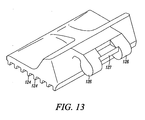
- a chamber 118 is provided in which a jaw is pivotally secured; the jaw is shown in Figure 13 and is held in the chamber 118 in the manner already described in connection with the first embodiment.
- the jaw is biased into the chamber 118 by resilient element 130 and the teeth on its lower surface engage with the teeth on the upper surface of the band, when located in the passage 115.
- the jaw 120 has the same configuration as the jaw 20 shown in Figures 7 to 9 with the exception that the teeth 124 extend all the way to the edge of the jaw and are of a slightly different shape.
- the means of connecting the jaw to the buckle via trunnions 126 and ledge 127 is identical to that of the first embodiment and the description will therefore not be repeated.
- the buckle has recesses 128 for accommodating the trunnions and a resilient element 130 for engaging the ledge 127 and allowing it to pivot upwardly within the chamber 118 so that the jaw can ride over the teeth of the band.
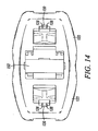
- the far ends 116 of the two passages 115 differ slightly from one another. As shown in Figure 11 , the right hand passage 115 ends in an upright wall 152 so that the end of a band pushed into the right hand passage abuts the wall 152 and cannot extend into a chamber 150. There is no corresponding wall in the left hand passage 115 and so the end of the band can be pushed into chamber 150.
- the jaws are fixed in chamber 118, as shown in Figure 14 and one end of the tooth band (not shown) is pushed into the right hand passage 115, see Figure 11 . It is pushed right up to the end wall 152 and is held within the passage 115 by the action of the teeth 124 on the jaws 120 engaging corresponding teeth on the outer surface of the band. Then, the band is formed into a closed loop around one or more objects and the free end is fed through entrance 116 of the left hand passage 115 and the end is fed through the passage into chamber 150. The end of the band that projects into chamber 150 can be grasped to apply tension to the band, optionally using a tool as shown in WO 2006/040524 .
- the teeth on the band used with the buckle of Figures 10 to 14 do not have a barbed shape but rather the teeth have a square or rectangular profile and the teeth on the jaw are similarly shaped (see Figure 13 ); asymmetric teeth on the band are not favoured in these circumstances since, although they may increase the resistance to the teeth at one end of the band from being pulled out from the buckle, the same shaped teeth will reduce the equivalent resistance at the other end of the band.
- a cover may be used to close the chamber 150.
- the buckle and band may be substantially as described in WO 2006/040524 , the contents of are incorporated herein by reference.
Landscapes
- Engineering & Computer Science (AREA)
- Mechanical Engineering (AREA)
- Package Frames And Binding Bands (AREA)
Claims (15)
- Schnalle (12) zur Verwendung mit einem Band (10) zum Bilden eines Befestigungselements, das ausgebildet ist, einen oder mehrere von dem Band (10) umgebene Gegenstände zusammenzudrücken oder festzuklemmen, wobei das Band (10) ein erstes (14) und ein zweites Ende und Zähne (11) aufweist, die an mindestens dem ersten Ende (14) vorgesehen sind und zur Verwendung beim Halten des Bandes (10) in einer geschlossenen Schleife, wobei die Schnalle (12) einen Körper, eine Klemmbacke (20) aufweist, die an dem Körper verbunden ist und mindestens einen Zahn (24) zum Eingriff mit den Zähnen (11) an dem ersten Ende (14) des Bandes (10) trägt und dadurch das erste Ende (14) des Bandes (10) hält, wenn in einer geschlossenen Schleife gebildet, und wobei der Schnallenkörper einen Durchgang (15) zum Halten eines Endes des Bandes (10) aufweist, wobei der Körper und die Klemmbacke (20) getrennte Bauteile sind und aus verschiedenen Materialien bestehen, dadurch gekennzeichnet, dass die Klemmbacke (20) elastisch in Richtung zum Durchgang (15) vorgespannt ist.
- Schnalle (12) gemäß Anspruch 1, wobei die Klemmbacke (20) elastisch zum Durchgang (15) mittels einer Feder, die einstückig mit dem Schnallenkörper ist, vorgespannt ist.
- Schnalle (12) gemäß einem der Ansprüche 1 und 2, wobei die Klemmbacke (20) aus einem Material mit einer größeren Steifigkeit und/oder Festigkeit als das Material, aus dem der Körper gebildet ist, besteht.
- Schnalle (12) gemäß einem der vorhergehenden Ansprüche, wobei die Klemmbacke (20) und der Körper jeweils aus einem unterschiedlichen geformten Kunststoffmaterial besteht.
- Schnalle (12) gemäß einem der vorhergehenden Ansprüche, wobei die Klemmbacke (20) und der mindestens eine Zahn (24), den sie trägt, aus Kunststoffmaterial bestehen, z. B. Nylon, wie z. B. Nylon 6.6, Nylon 11 oder Acetal oder Polypropylen, das mindestens eine Versteifung und/oder Verstärkung, z. B. Glas aufweist.
- Schnalle (12) gemäß einem der vorhergehenden Ansprüche, wobei der Körper aus Kunststoffmaterial besteht, z. B. Nylon, wie z. B. Nylon 6.6, Nylon 11 oder Acetal oder Polypropylen, das optional mindestens ein Verstärkungsmaterial, wie z. B. Glas aufweist.
- Schnalle (12) gemäß Anspruch 4, wobei der Körper und die Klemmbacke (20) beide aus demselben Ausgangskunststoffmaterial, z. B. Nylon, wie z. B. Nylon 6.6, Nylon 11 oder Acetal oder Polypropylen bestehen und die Klemmbacken (20) mindestens ein Verstärkungsmaterial, z. B. Glas, oder eine größere Beschickung mit dem Verstärkungsmaterial aufweisen.
- Schnalle (12) gemäß einem der vorhergehenden Ansprüche, wobei die Klemmbacke (20) schwenkbar, z. B. über ein Gelenk mit dem Körper verbunden ist, um zu ermöglichen, dass die Klemmbacke (20) von dem Durchgang (15) weggehoben wird, wenn ein Band (10) in den Durchgang (15) geschoben wird.
- Schnalle (12) gemäß Anspruch 7, wobei die Klemmbacke (20) Drehzapfen (26) aufweist, die schwenkbar in Ausnehmungen (20) in dem Körper gehalten sind und ein Gelenk bilden, um zu ermöglichen, dass die Klemmbacke (20) von dem Durchgang (15) weggehoben wird, wenn ein Band (10) in den Durchgang (15) geschoben wird.
- Schnalle (12) gemäß einem der Ansprüche 7 bis 9, wobei der mindestens eine Zahn (24) einen quadratischen oder rechteckigen Querschnitt aufweist.
- Schnalle (12) gemäß einem der vorhergehenden Ansprüche, wobei der mindestens eine Zahn (24) auf der Klemmbacke (20) Widerhaken aufweist und eine erste Fläche (40) hat, die schräg abfällt, um über die Bandzähne (11) zu laufen, wenn das Band (10) in die Schnalle (12) gedrückt wird, und eine zweite Fläche (42), die schräg abfällt, um die Klemmbacke (20) in näheren Eingriff mit dem Band (10) zu drücken, wenn eine Spannung in dem Band (10) dazu tendiert, das Band (10) aus der Schnalle (12) zu ziehen.
- Schnalle (12) gemäß einem der vorhergehenden Ansprüche, wobei der Körper eine zweite Klemmbacke aufweist, die mit dem Körper verbunden ist und mindestens einen Zahn zum Eingriff mit den Zähnen (11) an dem zweiten Ende des Bandes (10) trägt und dadurch das zweite Ende des Bandes (10) hält, wenn in einer geschlossenen Schleife gebildet, wobei die zweite Klemmbacke und der mindestens eine Zahn, den sie trägt, aus einem Material bestehen, das von dem Material des Körpers verschieden ist, und wobei optional die zweite Klemmbacke die in einem der Ansprüche 1 bis 11 für die erste Klemmbacke angegebenen Merkmale aufweist.
- Befestigungselement mit einer Schnalle (12), wie in einem der vorhergehenden Ansprüche definiert, und einem Band (10) mit einem ersten (14) und einem zweiten Ende und Zähnen (11), die an mindestens dem ersten Ende (14) vorgesehen sind, wobei das Befestigungselement ausgebildet ist, um einen Gegenstand oder Gegenstände, der oder die von dem Band (10) umgeben ist bzw. sind, zusammenzudrücken oder festzuklemmen.
- Befestigungselement gemäß Anspruch 13, wenn abhängig von einem der Ansprüche 1 bis 11, wobei das Band (10) einstückig mit der Schnalle (12) ist.
- Befestigungselement gemäß Anspruch 13, wenn abhängig von Anspruch 12 oder Anspruch 13, wobei das Band (10) von der Schnalle (12) trennbar ist und Zähne (11) an seinem ersten (14) und zweiten Ende aufweist.
Applications Claiming Priority (2)
| Application Number | Priority Date | Filing Date | Title |
|---|---|---|---|
| GB0712410A GB0712410D0 (en) | 2007-06-26 | 2007-06-26 | Fastening band |
| PCT/GB2008/002176 WO2009001079A1 (en) | 2007-06-26 | 2008-06-25 | Fastener |
Publications (2)
| Publication Number | Publication Date |
|---|---|
| EP2164768A1 EP2164768A1 (de) | 2010-03-24 |
| EP2164768B1 true EP2164768B1 (de) | 2013-08-14 |
Family
ID=38420757
Family Applications (1)
| Application Number | Title | Priority Date | Filing Date |
|---|---|---|---|
| EP08762483.9A Active EP2164768B1 (de) | 2007-06-26 | 2008-06-25 | Schnalle und Befestigungsband mit einer solchen Schnalle |
Country Status (5)
| Country | Link |
|---|---|
| EP (1) | EP2164768B1 (de) |
| AU (1) | AU2008269567B2 (de) |
| CA (1) | CA2694346C (de) |
| GB (1) | GB0712410D0 (de) |
| WO (1) | WO2009001079A1 (de) |
Families Citing this family (4)
| Publication number | Priority date | Publication date | Assignee | Title |
|---|---|---|---|---|
| US9340339B2 (en) | 2011-09-30 | 2016-05-17 | Thomas & Betts International Llc | Cable tie with dissimilar material barb |
| FR3050242B1 (fr) | 2016-04-15 | 2018-09-07 | Ses-Sterling Industrie-Holding Ag | Collier de serrage |
| GB2559392B (en) * | 2017-02-03 | 2019-05-22 | Hcl Fasteners Ltd | Fasteners |
| GR20180100469A (el) * | 2018-10-16 | 2020-05-18 | Παναγιωτης Ιωαννη Μπιλιας | Ιμαντας προσδεσης απλωστρας ρουχων για τη σταθεροποιηση της |
Citations (1)
| Publication number | Priority date | Publication date | Assignee | Title |
|---|---|---|---|---|
| US4999846A (en) * | 1990-03-09 | 1991-03-19 | Safeco Mfg. Limited | Strap and buckle assembly |
Family Cites Families (9)
| Publication number | Priority date | Publication date | Assignee | Title |
|---|---|---|---|---|
| GB1600601A (en) | 1977-03-17 | 1981-10-21 | Lea Bridge Sandblast Co Ltd | Hose clip |
| JPH0182165U (de) | 1987-11-18 | 1989-06-01 | ||
| GB8905987D0 (en) | 1989-03-15 | 1989-04-26 | Cobra Marketing Limited | Improvements in or relating to ties |
| CA2027720A1 (en) * | 1990-10-16 | 1992-04-17 | Claude Mauffette | Belt |
| US5230541A (en) | 1992-07-31 | 1993-07-27 | Kiddie Products, Inc. | Cabinet fastener |
| US5774953A (en) * | 1997-05-01 | 1998-07-07 | Mao; Chen Shou | Buckling device for baggage and the like |
| US6981725B2 (en) * | 2004-01-29 | 2006-01-03 | E. J. Brooks Company | Pull seal with bi-directional locking arrangement |
| GB0422548D0 (en) * | 2004-10-11 | 2004-11-10 | Hcl Fasteners Ltd | Fastening band |
| US7259674B2 (en) | 2004-12-22 | 2007-08-21 | Alpha Security Products, Inc. | Bottle security device |
-
2007
- 2007-06-26 GB GB0712410A patent/GB0712410D0/en not_active Ceased
-
2008
- 2008-06-25 AU AU2008269567A patent/AU2008269567B2/en not_active Ceased
- 2008-06-25 CA CA2694346A patent/CA2694346C/en not_active Expired - Fee Related
- 2008-06-25 WO PCT/GB2008/002176 patent/WO2009001079A1/en not_active Ceased
- 2008-06-25 EP EP08762483.9A patent/EP2164768B1/de active Active
Patent Citations (1)
| Publication number | Priority date | Publication date | Assignee | Title |
|---|---|---|---|---|
| US4999846A (en) * | 1990-03-09 | 1991-03-19 | Safeco Mfg. Limited | Strap and buckle assembly |
Also Published As
| Publication number | Publication date |
|---|---|
| GB0712410D0 (en) | 2007-08-08 |
| AU2008269567B2 (en) | 2013-03-14 |
| CA2694346A1 (en) | 2008-12-31 |
| WO2009001079A1 (en) | 2008-12-31 |
| CA2694346C (en) | 2015-02-17 |
| EP2164768A1 (de) | 2010-03-24 |
| AU2008269567A1 (en) | 2008-12-31 |
Similar Documents
| Publication | Publication Date | Title |
|---|---|---|
| RU2418933C2 (ru) | Защитное устройство, имеющее зацепляющийся элемент | |
| AU2008200480B2 (en) | Stop for slide fasteners | |
| US6347435B1 (en) | Rivet tie for coupling together two or more objects | |
| JP5820803B2 (ja) | 係止機構付き磁気ホック | |
| US20230157421A1 (en) | Magnetic buckle | |
| EP2164768B1 (de) | Schnalle und Befestigungsband mit einer solchen Schnalle | |
| US5758390A (en) | Reversible cable tie | |
| EP2140192B1 (de) | Binder zum umschlingen und bündeln von gegenständen | |
| US10472146B2 (en) | Key-releasable securing device | |
| US8978210B2 (en) | Adjustable-length tie-wrap | |
| EP2280881B1 (de) | Festziehbaren klemmvorrichtung für den einsatz in kabelbinder | |
| GB2327975A (en) | Holding device | |
| US9486040B2 (en) | Magnetically operated locking slider for zipper | |
| CA2589412A1 (en) | Security device having a cable | |
| TWI276407B (en) | Slider, slide fastener having the sliders, and bag having the slide fastener | |
| US20030140459A1 (en) | Locking strap with handling structure | |
| US10480688B2 (en) | High strength single piece cable tie locking mechanism | |
| JPH07507515A (ja) | 自転車,モーターバイクその他用のバッグの保持装置 | |
| WO2011139546A1 (en) | Zipper slider assembly | |
| US20030140461A1 (en) | Buckle | |
| US6536082B2 (en) | Tamper-proof tie | |
| CA2583305C (en) | Fastening band | |
| CN216888122U (zh) | 一种可以重复使用的扎带 | |
| KR101975950B1 (ko) | 자석체결버클 | |
| WO2006076081A2 (en) | Cabinet latch |
Legal Events
| Date | Code | Title | Description |
|---|---|---|---|
| PUAI | Public reference made under article 153(3) epc to a published international application that has entered the european phase |
Free format text: ORIGINAL CODE: 0009012 |
|
| 17P | Request for examination filed |
Effective date: 20100126 |
|
| AK | Designated contracting states |
Kind code of ref document: A1 Designated state(s): AT BE BG CH CY CZ DE DK EE ES FI FR GB GR HR HU IE IS IT LI LT LU LV MC MT NL NO PL PT RO SE SI SK TR |
|
| AX | Request for extension of the european patent |
Extension state: AL BA MK RS |
|
| DAX | Request for extension of the european patent (deleted) | ||
| 17Q | First examination report despatched |
Effective date: 20121221 |
|
| GRAP | Despatch of communication of intention to grant a patent |
Free format text: ORIGINAL CODE: EPIDOSNIGR1 |
|
| INTG | Intention to grant announced |
Effective date: 20130328 |
|
| GRAS | Grant fee paid |
Free format text: ORIGINAL CODE: EPIDOSNIGR3 |
|
| GRAA | (expected) grant |
Free format text: ORIGINAL CODE: 0009210 |
|
| AK | Designated contracting states |
Kind code of ref document: B1 Designated state(s): AT BE BG CH CY CZ DE DK EE ES FI FR GB GR HR HU IE IS IT LI LT LU LV MC MT NL NO PL PT RO SE SI SK TR |
|
| REG | Reference to a national code |
Ref country code: GB Ref legal event code: FG4D |
|
| REG | Reference to a national code |
Ref country code: CH Ref legal event code: EP Ref country code: AT Ref legal event code: REF Ref document number: 626671 Country of ref document: AT Kind code of ref document: T Effective date: 20130815 |
|
| REG | Reference to a national code |
Ref country code: IE Ref legal event code: FG4D |
|
| REG | Reference to a national code |
Ref country code: DE Ref legal event code: R096 Ref document number: 602008026795 Country of ref document: DE Effective date: 20131010 |
|
| REG | Reference to a national code |
Ref country code: NL Ref legal event code: T3 |
|
| REG | Reference to a national code |
Ref country code: NO Ref legal event code: T2 Effective date: 20130814 |
|
| REG | Reference to a national code |
Ref country code: AT Ref legal event code: MK05 Ref document number: 626671 Country of ref document: AT Kind code of ref document: T Effective date: 20130814 |
|
| REG | Reference to a national code |
Ref country code: LT Ref legal event code: MG4D |
|
| PG25 | Lapsed in a contracting state [announced via postgrant information from national office to epo] |
Ref country code: IS Free format text: LAPSE BECAUSE OF FAILURE TO SUBMIT A TRANSLATION OF THE DESCRIPTION OR TO PAY THE FEE WITHIN THE PRESCRIBED TIME-LIMIT Effective date: 20131214 Ref country code: SE Free format text: LAPSE BECAUSE OF FAILURE TO SUBMIT A TRANSLATION OF THE DESCRIPTION OR TO PAY THE FEE WITHIN THE PRESCRIBED TIME-LIMIT Effective date: 20130814 Ref country code: HR Free format text: LAPSE BECAUSE OF FAILURE TO SUBMIT A TRANSLATION OF THE DESCRIPTION OR TO PAY THE FEE WITHIN THE PRESCRIBED TIME-LIMIT Effective date: 20130814 Ref country code: AT Free format text: LAPSE BECAUSE OF FAILURE TO SUBMIT A TRANSLATION OF THE DESCRIPTION OR TO PAY THE FEE WITHIN THE PRESCRIBED TIME-LIMIT Effective date: 20130814 Ref country code: LT Free format text: LAPSE BECAUSE OF FAILURE TO SUBMIT A TRANSLATION OF THE DESCRIPTION OR TO PAY THE FEE WITHIN THE PRESCRIBED TIME-LIMIT Effective date: 20130814 Ref country code: CY Free format text: LAPSE BECAUSE OF FAILURE TO SUBMIT A TRANSLATION OF THE DESCRIPTION OR TO PAY THE FEE WITHIN THE PRESCRIBED TIME-LIMIT Effective date: 20130821 Ref country code: PT Free format text: LAPSE BECAUSE OF FAILURE TO SUBMIT A TRANSLATION OF THE DESCRIPTION OR TO PAY THE FEE WITHIN THE PRESCRIBED TIME-LIMIT Effective date: 20131216 |
|
| PG25 | Lapsed in a contracting state [announced via postgrant information from national office to epo] |
Ref country code: LV Free format text: LAPSE BECAUSE OF FAILURE TO SUBMIT A TRANSLATION OF THE DESCRIPTION OR TO PAY THE FEE WITHIN THE PRESCRIBED TIME-LIMIT Effective date: 20130814 Ref country code: GR Free format text: LAPSE BECAUSE OF FAILURE TO SUBMIT A TRANSLATION OF THE DESCRIPTION OR TO PAY THE FEE WITHIN THE PRESCRIBED TIME-LIMIT Effective date: 20131115 Ref country code: SI Free format text: LAPSE BECAUSE OF FAILURE TO SUBMIT A TRANSLATION OF THE DESCRIPTION OR TO PAY THE FEE WITHIN THE PRESCRIBED TIME-LIMIT Effective date: 20130814 Ref country code: BE Free format text: LAPSE BECAUSE OF FAILURE TO SUBMIT A TRANSLATION OF THE DESCRIPTION OR TO PAY THE FEE WITHIN THE PRESCRIBED TIME-LIMIT Effective date: 20130814 Ref country code: PL Free format text: LAPSE BECAUSE OF FAILURE TO SUBMIT A TRANSLATION OF THE DESCRIPTION OR TO PAY THE FEE WITHIN THE PRESCRIBED TIME-LIMIT Effective date: 20130814 Ref country code: FI Free format text: LAPSE BECAUSE OF FAILURE TO SUBMIT A TRANSLATION OF THE DESCRIPTION OR TO PAY THE FEE WITHIN THE PRESCRIBED TIME-LIMIT Effective date: 20130814 |
|
| PG25 | Lapsed in a contracting state [announced via postgrant information from national office to epo] |
Ref country code: CY Free format text: LAPSE BECAUSE OF FAILURE TO SUBMIT A TRANSLATION OF THE DESCRIPTION OR TO PAY THE FEE WITHIN THE PRESCRIBED TIME-LIMIT Effective date: 20130814 |
|
| PG25 | Lapsed in a contracting state [announced via postgrant information from national office to epo] |
Ref country code: EE Free format text: LAPSE BECAUSE OF FAILURE TO SUBMIT A TRANSLATION OF THE DESCRIPTION OR TO PAY THE FEE WITHIN THE PRESCRIBED TIME-LIMIT Effective date: 20130814 Ref country code: SK Free format text: LAPSE BECAUSE OF FAILURE TO SUBMIT A TRANSLATION OF THE DESCRIPTION OR TO PAY THE FEE WITHIN THE PRESCRIBED TIME-LIMIT Effective date: 20130814 Ref country code: CZ Free format text: LAPSE BECAUSE OF FAILURE TO SUBMIT A TRANSLATION OF THE DESCRIPTION OR TO PAY THE FEE WITHIN THE PRESCRIBED TIME-LIMIT Effective date: 20130814 Ref country code: RO Free format text: LAPSE BECAUSE OF FAILURE TO SUBMIT A TRANSLATION OF THE DESCRIPTION OR TO PAY THE FEE WITHIN THE PRESCRIBED TIME-LIMIT Effective date: 20130814 Ref country code: DK Free format text: LAPSE BECAUSE OF FAILURE TO SUBMIT A TRANSLATION OF THE DESCRIPTION OR TO PAY THE FEE WITHIN THE PRESCRIBED TIME-LIMIT Effective date: 20130814 |
|
| PG25 | Lapsed in a contracting state [announced via postgrant information from national office to epo] |
Ref country code: ES Free format text: LAPSE BECAUSE OF FAILURE TO SUBMIT A TRANSLATION OF THE DESCRIPTION OR TO PAY THE FEE WITHIN THE PRESCRIBED TIME-LIMIT Effective date: 20130814 |
|
| PLBE | No opposition filed within time limit |
Free format text: ORIGINAL CODE: 0009261 |
|
| STAA | Information on the status of an ep patent application or granted ep patent |
Free format text: STATUS: NO OPPOSITION FILED WITHIN TIME LIMIT |
|
| 26N | No opposition filed |
Effective date: 20140515 |
|
| REG | Reference to a national code |
Ref country code: DE Ref legal event code: R097 Ref document number: 602008026795 Country of ref document: DE Effective date: 20140515 |
|
| PG25 | Lapsed in a contracting state [announced via postgrant information from national office to epo] |
Ref country code: MC Free format text: LAPSE BECAUSE OF FAILURE TO SUBMIT A TRANSLATION OF THE DESCRIPTION OR TO PAY THE FEE WITHIN THE PRESCRIBED TIME-LIMIT Effective date: 20130814 Ref country code: LU Free format text: LAPSE BECAUSE OF FAILURE TO SUBMIT A TRANSLATION OF THE DESCRIPTION OR TO PAY THE FEE WITHIN THE PRESCRIBED TIME-LIMIT Effective date: 20140625 |
|
| REG | Reference to a national code |
Ref country code: CH Ref legal event code: PL |
|
| REG | Reference to a national code |
Ref country code: IE Ref legal event code: MM4A |
|
| PG25 | Lapsed in a contracting state [announced via postgrant information from national office to epo] |
Ref country code: CH Free format text: LAPSE BECAUSE OF NON-PAYMENT OF DUE FEES Effective date: 20140630 Ref country code: IE Free format text: LAPSE BECAUSE OF NON-PAYMENT OF DUE FEES Effective date: 20140625 Ref country code: LI Free format text: LAPSE BECAUSE OF NON-PAYMENT OF DUE FEES Effective date: 20140630 |
|
| PGFP | Annual fee paid to national office [announced via postgrant information from national office to epo] |
Ref country code: DE Payment date: 20150622 Year of fee payment: 8 Ref country code: NO Payment date: 20150624 Year of fee payment: 8 |
|
| PGFP | Annual fee paid to national office [announced via postgrant information from national office to epo] |
Ref country code: IT Payment date: 20150625 Year of fee payment: 8 |
|
| PG25 | Lapsed in a contracting state [announced via postgrant information from national office to epo] |
Ref country code: MT Free format text: LAPSE BECAUSE OF FAILURE TO SUBMIT A TRANSLATION OF THE DESCRIPTION OR TO PAY THE FEE WITHIN THE PRESCRIBED TIME-LIMIT Effective date: 20130814 |
|
| PG25 | Lapsed in a contracting state [announced via postgrant information from national office to epo] |
Ref country code: BG Free format text: LAPSE BECAUSE OF FAILURE TO SUBMIT A TRANSLATION OF THE DESCRIPTION OR TO PAY THE FEE WITHIN THE PRESCRIBED TIME-LIMIT Effective date: 20130814 |
|
| REG | Reference to a national code |
Ref country code: FR Ref legal event code: PLFP Year of fee payment: 9 |
|
| PG25 | Lapsed in a contracting state [announced via postgrant information from national office to epo] |
Ref country code: HU Free format text: LAPSE BECAUSE OF FAILURE TO SUBMIT A TRANSLATION OF THE DESCRIPTION OR TO PAY THE FEE WITHIN THE PRESCRIBED TIME-LIMIT; INVALID AB INITIO Effective date: 20080625 Ref country code: TR Free format text: LAPSE BECAUSE OF FAILURE TO SUBMIT A TRANSLATION OF THE DESCRIPTION OR TO PAY THE FEE WITHIN THE PRESCRIBED TIME-LIMIT Effective date: 20130814 |
|
| REG | Reference to a national code |
Ref country code: DE Ref legal event code: R119 Ref document number: 602008026795 Country of ref document: DE |
|
| REG | Reference to a national code |
Ref country code: NO Ref legal event code: MMEP |
|
| PG25 | Lapsed in a contracting state [announced via postgrant information from national office to epo] |
Ref country code: NO Free format text: LAPSE BECAUSE OF NON-PAYMENT OF DUE FEES Effective date: 20160630 Ref country code: DE Free format text: LAPSE BECAUSE OF NON-PAYMENT OF DUE FEES Effective date: 20170103 |
|
| REG | Reference to a national code |
Ref country code: FR Ref legal event code: PLFP Year of fee payment: 10 |
|
| PG25 | Lapsed in a contracting state [announced via postgrant information from national office to epo] |
Ref country code: IT Free format text: LAPSE BECAUSE OF NON-PAYMENT OF DUE FEES Effective date: 20160625 |
|
| REG | Reference to a national code |
Ref country code: FR Ref legal event code: PLFP Year of fee payment: 11 |
|
| PGFP | Annual fee paid to national office [announced via postgrant information from national office to epo] |
Ref country code: NL Payment date: 20190614 Year of fee payment: 12 |
|
| PGFP | Annual fee paid to national office [announced via postgrant information from national office to epo] |
Ref country code: FR Payment date: 20190625 Year of fee payment: 12 |
|
| REG | Reference to a national code |
Ref country code: NL Ref legal event code: MM Effective date: 20200701 |
|
| PG25 | Lapsed in a contracting state [announced via postgrant information from national office to epo] |
Ref country code: FR Free format text: LAPSE BECAUSE OF NON-PAYMENT OF DUE FEES Effective date: 20200630 Ref country code: NL Free format text: LAPSE BECAUSE OF NON-PAYMENT OF DUE FEES Effective date: 20200701 |
|
| PGFP | Annual fee paid to national office [announced via postgrant information from national office to epo] |
Ref country code: GB Payment date: 20250613 Year of fee payment: 18 |