EP2163907A2 - Ausleger mit Paddel zum Betrieb im Doppelfrequenzmodus - Google Patents
Ausleger mit Paddel zum Betrieb im Doppelfrequenzmodus Download PDFInfo
- Publication number
- EP2163907A2 EP2163907A2 EP09169270A EP09169270A EP2163907A2 EP 2163907 A2 EP2163907 A2 EP 2163907A2 EP 09169270 A EP09169270 A EP 09169270A EP 09169270 A EP09169270 A EP 09169270A EP 2163907 A2 EP2163907 A2 EP 2163907A2
- Authority
- EP
- European Patent Office
- Prior art keywords
- paddle
- cantilever
- vibration
- sample
- tip
- Prior art date
- Legal status (The legal status is an assumption and is not a legal conclusion. Google has not performed a legal analysis and makes no representation as to the accuracy of the status listed.)
- Withdrawn
Links
Images
Classifications
-
- G—PHYSICS
- G01—MEASURING; TESTING
- G01Q—SCANNING-PROBE TECHNIQUES OR APPARATUS; APPLICATIONS OF SCANNING-PROBE TECHNIQUES, e.g. SCANNING PROBE MICROSCOPY [SPM]
- G01Q60/00—Particular types of SPM [Scanning Probe Microscopy] or microscopes; Essential components thereof
- G01Q60/24—AFM [Atomic Force Microscopy] or apparatus therefor, e.g. AFM probes
- G01Q60/32—AC mode
-
- G—PHYSICS
- G01—MEASURING; TESTING
- G01Q—SCANNING-PROBE TECHNIQUES OR APPARATUS; APPLICATIONS OF SCANNING-PROBE TECHNIQUES, e.g. SCANNING PROBE MICROSCOPY [SPM]
- G01Q20/00—Monitoring the movement or position of the probe
- G01Q20/04—Self-detecting probes, i.e. wherein the probe itself generates a signal representative of its position, e.g. piezoelectric gauge
-
- G—PHYSICS
- G01—MEASURING; TESTING
- G01Q—SCANNING-PROBE TECHNIQUES OR APPARATUS; APPLICATIONS OF SCANNING-PROBE TECHNIQUES, e.g. SCANNING PROBE MICROSCOPY [SPM]
- G01Q60/00—Particular types of SPM [Scanning Probe Microscopy] or microscopes; Essential components thereof
- G01Q60/24—AFM [Atomic Force Microscopy] or apparatus therefor, e.g. AFM probes
- G01Q60/38—Probes, their manufacture, or their related instrumentation, e.g. holders
-
- G—PHYSICS
- G01—MEASURING; TESTING
- G01Q—SCANNING-PROBE TECHNIQUES OR APPARATUS; APPLICATIONS OF SCANNING-PROBE TECHNIQUES, e.g. SCANNING PROBE MICROSCOPY [SPM]
- G01Q70/00—General aspects of SPM probes, their manufacture or their related instrumentation, insofar as they are not specially adapted to a single SPM technique covered by group G01Q60/00
- G01Q70/08—Probe characteristics
- G01Q70/10—Shape or taper
Definitions
- the instant invention concerns specific microcantilevers and their use in atomic force microscopy.
- the atomic force microscope has become a standard instrument in nano-analysis with regards to the rapid and uncomplicated technical exploration of surfaces at the micro- and nanometre scales.
- AFM atomic force microscope
- a probe mounted at the end of a cantilever beam is generally placed in direct contact with the sample, such that the surface topography is obtained through a raster scan while maintaining a constant tip-sample force.
- An important upgrade to this basic process is the so-called dynamic AFM mode, whereby the cantilever oscillates near the surface while changes in the oscillation amplitude are monitored while also recording the relative position of the tip and the sample. If one uses the amplitude change as the control signal, it is possible to measure the sample topography with high vertical and lateral resolution.
- the resonant frequency of the cantilever can be measured as a function of the tip-sample separation, from which the tip-sample interaction force can be obtained ( Hölscher et al., Phys. Rev. B 61, 12678 (2000 )).
- these additional measurements can only be performed through a subsequent characterization after scanning of the surface topography.
- the tip moves laterally in an undefined pattern and the lateral frequency of the tip is only slightly higher than the normal motion (typically below 20:1).
- the demands on the system electronics are so high that one can only use the specifically-designed, original electronics of the manufacturer Veeco Instruments, who have exclusively commercialized this technique under the name Harmonix ( WO2006/014542 A1 ).
- the manufacturing of miniature paddles is described in Evoy et al. [J. Appl. Phys. 86, 6072 (1999 )] and Boonliang et al. [J. Micromech. Microeng. 18, 015021 (2008 )]), the use of such paddles in cantilevers for AFM is not described.
- the objects of the instant invention have been solved by a specifically designed cantilever/cantilever system and its use in atomic force microscopy.
- cantilever In the instant invention the terms "cantilever”, “cantilever system”, “microcantilever” and “microcantilever system” are used synonymously.
- the paddles of the instant invention's cantilevers can be designed to oscillate at frequencies that are significantly higher (1-1000 MHz) than the fundamental frequency of the cantilever (a few tens of kHz).
- the fundamental frequency of the cantilever a few tens of kHz.
- the design according to the instant invention ensures that the oscillation of the cantilever, which is used to acquire the sample topography, is nearly completely decoupled from the oscillation of the paddle, which is used to detect the tip-sample interactions.
- the oscillation of the paddle is brought about either by intermittent contact between the probe and the sample, or by AFM excitation schemes. This way it was found possible to obtain complete decoupling of the imaging and spectroscopy, and was found possible to simultaneously acquire the topography and measure the tip-sample interactions by the instant invention.
- the instant invention provides a novel atomic force microscopy (AFM) microcantilever/microcantilever system of specific design, namely one containing a paddle built or cut into the distal end of the microcantilever.
- the microcantilever itself can be of of varying shape, including shapes as rectangular, V-shaped, etc.
- the paddle can also be of varying, not-necessarily symmetric shape including shapes as square, rectangular, oval-shaped, etc.
- the paddle has a tip or probe attached to it, which is suitable for AFM characterization, and which is caused to oscillate towards and away from the sample surface in the nearly normal direction when the paddle vibrates.
- the cantilever itself is of rectangular shape and the paddle is of square shape, the cantilever and the paddle being connected by small rods/supporting beams.
- the paddle can be located symmetrically centred at the distal end of the cantilever.
- the paddle is located on one side of the distal end of the cantilever. It is also possible in another embodiment of the instant invention, that the distal end of the cantilever itself has an extension to one side or extensions to both sides (making it L-shaped or T-shaped) and the paddle is located in either one or both extensions of the cantilever.
- the cantilever can also be asymmetric in various ways, including curved.
- the supporting beams that connect the paddle with the cantilever itself can be located anywhere on the sides of the paddle, including somewhere in the middle of the paddle-sides or on the one or other end of the paddle-sides (making it look as if the paddle was a flag, either extending outward from the cantilever or inward).
- the paddle's vibration does not perturb the flexural vibration of the cantilever, and has a fundamental resonance frequency between the cantilever's fundamental resonance frequency and hundreds of megahertz, such that this frequency can be designed into the system through selection of the appropriate paddle and supporting beam dimensions.
- the cantilever itself can for example have a length of 50 - 500 ⁇ m, a width of 10 - 100 ⁇ m and a thickness of 1 - 10 ⁇ m.
- the dimensions of the paddle depend on the cantilever size, preferably it can have a length of 10 - 100 ⁇ m, a width of 10 - 100 ⁇ m and a thickness of 1 - 10 um.
- One example of a cantilever produced according to the instant invention had dimensions of 225 ⁇ m by 38 ⁇ m by 7 ⁇ m with trapezoidal cross section, having a force constant of 48 N/m and a resonance frequency of 190 kHz with a paddle having dimensions of 10 ⁇ m by 10 ⁇ m.
- Other paddles produced according to the instant invention had dimensions of 25 ⁇ m by 16 ⁇ m, 37 ⁇ m by 33 ⁇ m, 19 ⁇ m by 12 ⁇ m and 60 ⁇ m by 36 ⁇ m, with cantilevers of appropriate dimensions.
- the tip response of the instant invention's cantilever has the form of a high high-frequency response curve (the "spectroscopy curve") superimposed over a low-frequency response curve (the “imaging curve”).
- the cantilever itself oscillates with a low frequency, which can be used for imaging (thus resulting in the "imaging curve”).
- the tip/the paddle oscillates with a high frequency and small amplitude, which can be used for force spectroscopy (thus resulting in the"spectroscopy curve").
- the paddle may be machined on existing standard commercial cantilevers through techniques such as focused-ion-beam (FIB) etching.
- FIB focused-ion-beam
- the ensemble can be manufactured by using standard micromachining methods.
- the material of the instant invention's cantilever can be any material capable of producing standard AFM microcantilevers.
- Examples for materials that can be used according to the instant invention include silicon and silicon nitride (Si 3 N 4 ).
- the oscillation of the paddle is brought about either by intermittent contact between the probe and the sample during flexural vibration of the cantilever, or by conventional AFM excitation schemes which include piezoelectric, magnetic, excitation schemes governed by the AFM instrument's controls systems.
- the tracking of the vibration of the paddle and of the flexural vibration of the cantilever can be
- the flexural vibration of the cantilever is completely decoupled from the vibration of the paddle such that these two modes of vibration do not interfere with one another.
- the instant invention also encompasses the use of the inventive microcantilever system for AFM characterization in vacuum, air and liquids, whereby
- TMR tunnel magnetoresistance
- the instant invention's novel cantilever can be used for the following purposes.
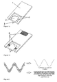
- Figure 1 shows two exemplary embodiments of the instant invention's cantilever systems.
- the cantilever 1 is of rectangular shape and the paddle 2 is of square shape having a tip or probe 3 on its underside, the cantilever 1 and the paddle 2 being connected by small rods/supporting beams 4.
- the paddle 2 is located symmetrically centred at the distal end of the cantilever 1, the supporting beams 4 that connect the paddle 2 with the cantilever 1, are shown in figures 1a and 1b in the middle of the paddle-sides.
- figure 1a The only difference between figure 1a and figure 1b is that in figure 1b three piezoelectric sensors or sensors based on tunnel magnetoresistance (TMR) 5 are shown whereby these sensors 5 are placed at the base of the cantilever 1 and on the supporting structural members 4 of the paddle 2.
- TMR tunnel magnetoresistance
- Figure 2 shows that the tip response of the instant invention's cantilever has the form of a high high-frequency response curve (the "spectroscopy curve") superimposed over a low-frequency response curve (the “imaging curve”).
Landscapes
- Physics & Mathematics (AREA)
- Health & Medical Sciences (AREA)
- General Health & Medical Sciences (AREA)
- General Physics & Mathematics (AREA)
- Nuclear Medicine, Radiotherapy & Molecular Imaging (AREA)
- Radiology & Medical Imaging (AREA)
- Engineering & Computer Science (AREA)
- Power Engineering (AREA)
- Length Measuring Devices With Unspecified Measuring Means (AREA)
Applications Claiming Priority (1)
| Application Number | Priority Date | Filing Date | Title |
|---|---|---|---|
| US9694308P | 2008-09-15 | 2008-09-15 |
Publications (2)
| Publication Number | Publication Date |
|---|---|
| EP2163907A2 true EP2163907A2 (de) | 2010-03-17 |
| EP2163907A3 EP2163907A3 (de) | 2010-09-29 |
Family
ID=41463193
Family Applications (1)
| Application Number | Title | Priority Date | Filing Date |
|---|---|---|---|
| EP09169270A Withdrawn EP2163907A3 (de) | 2008-09-15 | 2009-09-02 | Ausleger mit Paddel zum Betrieb im Doppelfrequenzmodus |
Country Status (1)
| Country | Link |
|---|---|
| EP (1) | EP2163907A3 (de) |
Cited By (3)
| Publication number | Priority date | Publication date | Assignee | Title |
|---|---|---|---|---|
| EP3447504A1 (de) * | 2017-08-24 | 2019-02-27 | Nederlandse Organisatie voor toegepast- natuurwetenschappelijk onderzoek TNO | Cantilever für rasterkraftmikroskopie, system und verfahren |
| US10648786B2 (en) | 2017-09-01 | 2020-05-12 | Nanohmics, Inc. | Magnetoelastic sensor for analyzing strain |
| WO2020227222A1 (en) | 2019-05-03 | 2020-11-12 | Bruker Nano, Inc. | Torsion wing probe assembly |
Citations (2)
| Publication number | Priority date | Publication date | Assignee | Title |
|---|---|---|---|---|
| WO2006014542A1 (en) | 2004-07-08 | 2006-02-09 | The Board Of Trustees Of The Leland Stanford Junior University | Torsional harmonic cantilevers for detection of high frequency force components in atomic force microscopy |
| WO2007024711A2 (en) | 2005-08-19 | 2007-03-01 | Arthur Beyder | Oscillator and method of making for atomic force microscope and other applications |
-
2009
- 2009-09-02 EP EP09169270A patent/EP2163907A3/de not_active Withdrawn
Patent Citations (2)
| Publication number | Priority date | Publication date | Assignee | Title |
|---|---|---|---|---|
| WO2006014542A1 (en) | 2004-07-08 | 2006-02-09 | The Board Of Trustees Of The Leland Stanford Junior University | Torsional harmonic cantilevers for detection of high frequency force components in atomic force microscopy |
| WO2007024711A2 (en) | 2005-08-19 | 2007-03-01 | Arthur Beyder | Oscillator and method of making for atomic force microscope and other applications |
Non-Patent Citations (10)
| Title |
|---|
| BOONLIANG ET AL., J. MICROMECH. MICROENG, vol. 18, 2008, pages 015021 |
| D.W. LEE ET AL.: "Cantilever with integrated resonator for application of scanning probe microscope", SENSORS AND ACTUATORS, vol. 83, 2000, pages 11 - 16, XP004198286, DOI: doi:10.1016/S0924-4247(99)00378-7 |
| EVOY ET AL., J. APPL. PHYS., vol. 86, 1999, pages 6072 |
| H61SCHER ET AL., APPL. SURF. SCI., vol. 140, 1999, pages 344 |
| H61SCHER ET AL., PHYS. REV. B, vol. 61, 2000, pages 12678 |
| HOISCHER ET AL., PHYS. REV. B, vol. 61, 2000, pages 12678 |
| LEGLEITER ET AL., PNAS, vol. 103, 2006, pages 4813 |
| SAHIN ET AL., NATURE NANOTECHNOLOGY, vol. 2, 2007, pages 507 |
| SOLARES; CHAWLA, MEAS. SCI. TECHNOL., vol. 19, 2008, pages 055502 |
| STARK ET AL., PNAS, vol. 99, 2002, pages 8473 |
Cited By (11)
| Publication number | Priority date | Publication date | Assignee | Title |
|---|---|---|---|---|
| EP3447504A1 (de) * | 2017-08-24 | 2019-02-27 | Nederlandse Organisatie voor toegepast- natuurwetenschappelijk onderzoek TNO | Cantilever für rasterkraftmikroskopie, system und verfahren |
| WO2019039941A1 (en) * | 2017-08-24 | 2019-02-28 | Nederlandse Organisatie Voor Toegepast- Natuurwetenschappelijk Onderzoek Tno | ATOMIC FORCE MICROSCOPY MICROLEVIER, SYSTEM AND METHOD |
| TWI769296B (zh) * | 2017-08-24 | 2022-07-01 | 荷蘭商荷蘭Tno自然科學組織公司 | 原子力顯微鏡懸臂、系統及方法 |
| US11644481B2 (en) | 2017-08-24 | 2023-05-09 | Nederlandse Organisatie voor toegepast-nataurwetenschappelijk onderzoek TNO | Atomic force microscopy cantilever, system and method |
| US10648786B2 (en) | 2017-09-01 | 2020-05-12 | Nanohmics, Inc. | Magnetoelastic sensor for analyzing strain |
| WO2020227222A1 (en) | 2019-05-03 | 2020-11-12 | Bruker Nano, Inc. | Torsion wing probe assembly |
| KR20210150608A (ko) * | 2019-05-03 | 2021-12-10 | 브루커 나노, 아이엔씨. | 토션 윙 프로브 어셈블리 |
| CN114026438A (zh) * | 2019-05-03 | 2022-02-08 | 布鲁克纳米公司 | 扭转翼探针组件 |
| JP2022530987A (ja) * | 2019-05-03 | 2022-07-05 | ブルカー ナノ インコーポレイテッド | トーションウイングプローブアセンブリ |
| EP3963341A4 (de) * | 2019-05-03 | 2023-01-18 | Bruker Nano, Inc. | Torsionsflügelsondenanordnung |
| CN114026438B (zh) * | 2019-05-03 | 2024-09-24 | 布鲁克纳米公司 | 扭转翼探针组件 |
Also Published As
| Publication number | Publication date |
|---|---|
| EP2163907A3 (de) | 2010-09-29 |
Similar Documents
| Publication | Publication Date | Title |
|---|---|---|
| US5866807A (en) | Method and apparatus for measuring mechanical properties on a small scale | |
| US7302833B2 (en) | Torsional harmonic cantilevers for detection of high frequency force components in atomic force microscopy | |
| Moreno-Herrero et al. | Atomic force microscopy contact, tapping, and jumping modes for imaging biological samples in liquids | |
| US6220084B1 (en) | Detecting fields with a single-pass, dual-amplitude-mode scanning force microscope | |
| US7603891B2 (en) | Multiple frequency atomic force microscopy | |
| Tortonese | Cantilevers and tips for atomic force microscopy | |
| US6945099B1 (en) | Torsional resonance mode probe-based instrument and method | |
| US20120079631A1 (en) | Material Property Measurements Using Multiple Frequency Atomic Fore Microscopy | |
| EP1482297A4 (de) | Rastersondenmikroskop sowie verfahren zur messung der oberflächenstruktur von präparaten | |
| US9535085B2 (en) | Intermittent contact resonance atomic force microscope and process for intermittent contact resonance atomic force microscopy | |
| WO2006029292A2 (en) | Method and apparatus of driving torsional resonance mode of a probe-based instrument | |
| US8250668B2 (en) | Cantilever with paddle for operation in dual-frequency mode | |
| US6415653B1 (en) | Cantilever for use in a scanning probe microscope | |
| JP2011089985A (ja) | 原子間力顕微鏡の探針を特徴づけるための方法および構造 | |
| EP2163907A2 (de) | Ausleger mit Paddel zum Betrieb im Doppelfrequenzmodus | |
| JP2000346784A (ja) | 粘弾性分布測定方法 | |
| WO2009043368A1 (en) | Colloid-sensor for afm | |
| CN114787638A (zh) | 原子力显微镜 | |
| CN114026438B (zh) | 扭转翼探针组件 | |
| US20250052781A1 (en) | Atomic Force Microscopy Probe with Tilted Tip and Method of Fabrication Thereof | |
| Yu et al. | A scanning probe microscope for surface measurement in nano-scale | |
| US20250277809A1 (en) | Probe-Based Instrument and Method Using Torsional Oscillation Sensing | |
| US11719719B2 (en) | Metrology probe with built-in angle and method of fabrication thereof | |
| US9091704B2 (en) | Method for controlling a scanning microscope | |
| Sbrana et al. | Atomic force microscopy study on the pellicle of the alga Euglena gracilis |
Legal Events
| Date | Code | Title | Description |
|---|---|---|---|
| PUAI | Public reference made under article 153(3) epc to a published international application that has entered the european phase |
Free format text: ORIGINAL CODE: 0009012 |
|
| AK | Designated contracting states |
Kind code of ref document: A2 Designated state(s): AT BE BG CH CY CZ DE DK EE ES FI FR GB GR HR HU IE IS IT LI LT LU LV MC MK MT NL NO PL PT RO SE SI SK SM TR |
|
| AX | Request for extension of the european patent |
Extension state: AL BA RS |
|
| PUAL | Search report despatched |
Free format text: ORIGINAL CODE: 0009013 |
|
| AK | Designated contracting states |
Kind code of ref document: A3 Designated state(s): AT BE BG CH CY CZ DE DK EE ES FI FR GB GR HR HU IE IS IT LI LT LU LV MC MK MT NL NO PL PT RO SE SI SK SM TR |
|
| AX | Request for extension of the european patent |
Extension state: AL BA RS |
|
| RIC1 | Information provided on ipc code assigned before grant |
Ipc: G01Q 60/32 20100101ALI20100824BHEP Ipc: G01Q 60/38 20100101AFI20100111BHEP Ipc: G01Q 70/10 20100101ALI20100824BHEP |
|
| 17P | Request for examination filed |
Effective date: 20110216 |
|
| 17Q | First examination report despatched |
Effective date: 20161110 |
|
| RIC1 | Information provided on ipc code assigned before grant |
Ipc: G01Q 20/04 20100101ALI20181002BHEP Ipc: G01Q 60/32 20100101ALI20181002BHEP Ipc: G01Q 60/38 20100101AFI20181002BHEP Ipc: G01Q 70/10 20100101ALI20181002BHEP |
|
| STAA | Information on the status of an ep patent application or granted ep patent |
Free format text: STATUS: THE APPLICATION IS DEEMED TO BE WITHDRAWN |
|
| 18D | Application deemed to be withdrawn |
Effective date: 20190216 |