EP2163857A1 - Magnetic encoder and rolling bearing - Google Patents
Magnetic encoder and rolling bearing Download PDFInfo
- Publication number
- EP2163857A1 EP2163857A1 EP08777826A EP08777826A EP2163857A1 EP 2163857 A1 EP2163857 A1 EP 2163857A1 EP 08777826 A EP08777826 A EP 08777826A EP 08777826 A EP08777826 A EP 08777826A EP 2163857 A1 EP2163857 A1 EP 2163857A1
- Authority
- EP
- European Patent Office
- Prior art keywords
- slinger
- inner ring
- magnetic encoder
- magnetized
- based adhesive
- Prior art date
- Legal status (The legal status is an assumption and is not a legal conclusion. Google has not performed a legal analysis and makes no representation as to the accuracy of the status listed.)
- Granted
Links
Images


Classifications
-
- F—MECHANICAL ENGINEERING; LIGHTING; HEATING; WEAPONS; BLASTING
- F16—ENGINEERING ELEMENTS AND UNITS; GENERAL MEASURES FOR PRODUCING AND MAINTAINING EFFECTIVE FUNCTIONING OF MACHINES OR INSTALLATIONS; THERMAL INSULATION IN GENERAL
- F16C—SHAFTS; FLEXIBLE SHAFTS; ELEMENTS OR CRANKSHAFT MECHANISMS; ROTARY BODIES OTHER THAN GEARING ELEMENTS; BEARINGS
- F16C33/00—Parts of bearings; Special methods for making bearings or parts thereof
- F16C33/72—Sealings
- F16C33/76—Sealings of ball or roller bearings
- F16C33/78—Sealings of ball or roller bearings with a diaphragm, disc, or ring, with or without resilient members
- F16C33/7869—Sealings of ball or roller bearings with a diaphragm, disc, or ring, with or without resilient members mounted with a cylindrical portion to the inner surface of the outer race and having a radial portion extending inward
- F16C33/7879—Sealings of ball or roller bearings with a diaphragm, disc, or ring, with or without resilient members mounted with a cylindrical portion to the inner surface of the outer race and having a radial portion extending inward with a further sealing ring
-
- F—MECHANICAL ENGINEERING; LIGHTING; HEATING; WEAPONS; BLASTING
- F16—ENGINEERING ELEMENTS AND UNITS; GENERAL MEASURES FOR PRODUCING AND MAINTAINING EFFECTIVE FUNCTIONING OF MACHINES OR INSTALLATIONS; THERMAL INSULATION IN GENERAL
- F16C—SHAFTS; FLEXIBLE SHAFTS; ELEMENTS OR CRANKSHAFT MECHANISMS; ROTARY BODIES OTHER THAN GEARING ELEMENTS; BEARINGS
- F16C41/00—Other accessories, e.g. devices integrated in the bearing not relating to the bearing function as such
- F16C41/007—Encoders, e.g. parts with a plurality of alternating magnetic poles
-
- F—MECHANICAL ENGINEERING; LIGHTING; HEATING; WEAPONS; BLASTING
- F16—ENGINEERING ELEMENTS AND UNITS; GENERAL MEASURES FOR PRODUCING AND MAINTAINING EFFECTIVE FUNCTIONING OF MACHINES OR INSTALLATIONS; THERMAL INSULATION IN GENERAL
- F16J—PISTONS; CYLINDERS; SEALINGS
- F16J15/00—Sealings
- F16J15/16—Sealings between relatively-moving surfaces
- F16J15/32—Sealings between relatively-moving surfaces with elastic sealings, e.g. O-rings
- F16J15/3248—Sealings between relatively-moving surfaces with elastic sealings, e.g. O-rings provided with casings or supports
- F16J15/3252—Sealings between relatively-moving surfaces with elastic sealings, e.g. O-rings provided with casings or supports with rigid casings or supports
- F16J15/3256—Sealings between relatively-moving surfaces with elastic sealings, e.g. O-rings provided with casings or supports with rigid casings or supports comprising two casing or support elements, one attached to each surface, e.g. cartridge or cassette seals
- F16J15/326—Sealings between relatively-moving surfaces with elastic sealings, e.g. O-rings provided with casings or supports with rigid casings or supports comprising two casing or support elements, one attached to each surface, e.g. cartridge or cassette seals with means for detecting or measuring relative rotation of the two elements
-
- G—PHYSICS
- G01—MEASURING; TESTING
- G01P—MEASURING LINEAR OR ANGULAR SPEED, ACCELERATION, DECELERATION, OR SHOCK; INDICATING PRESENCE, ABSENCE, OR DIRECTION, OF MOVEMENT
- G01P3/00—Measuring linear or angular speed; Measuring differences of linear or angular speeds
- G01P3/42—Devices characterised by the use of electric or magnetic means
- G01P3/44—Devices characterised by the use of electric or magnetic means for measuring angular speed
- G01P3/443—Devices characterised by the use of electric or magnetic means for measuring angular speed mounted in bearings
-
- G—PHYSICS
- G01—MEASURING; TESTING
- G01P—MEASURING LINEAR OR ANGULAR SPEED, ACCELERATION, DECELERATION, OR SHOCK; INDICATING PRESENCE, ABSENCE, OR DIRECTION, OF MOVEMENT
- G01P3/00—Measuring linear or angular speed; Measuring differences of linear or angular speeds
- G01P3/42—Devices characterised by the use of electric or magnetic means
- G01P3/44—Devices characterised by the use of electric or magnetic means for measuring angular speed
- G01P3/48—Devices characterised by the use of electric or magnetic means for measuring angular speed by measuring frequency of generated current or voltage
- G01P3/481—Devices characterised by the use of electric or magnetic means for measuring angular speed by measuring frequency of generated current or voltage of pulse signals
- G01P3/487—Devices characterised by the use of electric or magnetic means for measuring angular speed by measuring frequency of generated current or voltage of pulse signals delivered by rotating magnets
-
- F—MECHANICAL ENGINEERING; LIGHTING; HEATING; WEAPONS; BLASTING
- F16—ENGINEERING ELEMENTS AND UNITS; GENERAL MEASURES FOR PRODUCING AND MAINTAINING EFFECTIVE FUNCTIONING OF MACHINES OR INSTALLATIONS; THERMAL INSULATION IN GENERAL
- F16C—SHAFTS; FLEXIBLE SHAFTS; ELEMENTS OR CRANKSHAFT MECHANISMS; ROTARY BODIES OTHER THAN GEARING ELEMENTS; BEARINGS
- F16C2226/00—Joining parts; Fastening; Assembling or mounting parts
- F16C2226/30—Material joints
- F16C2226/40—Material joints with adhesive
-
- F—MECHANICAL ENGINEERING; LIGHTING; HEATING; WEAPONS; BLASTING
- F16—ENGINEERING ELEMENTS AND UNITS; GENERAL MEASURES FOR PRODUCING AND MAINTAINING EFFECTIVE FUNCTIONING OF MACHINES OR INSTALLATIONS; THERMAL INSULATION IN GENERAL
- F16C—SHAFTS; FLEXIBLE SHAFTS; ELEMENTS OR CRANKSHAFT MECHANISMS; ROTARY BODIES OTHER THAN GEARING ELEMENTS; BEARINGS
- F16C2326/00—Articles relating to transporting
- F16C2326/01—Parts of vehicles in general
- F16C2326/02—Wheel hubs or castors
-
- G—PHYSICS
- G01—MEASURING; TESTING
- G01D—MEASURING NOT SPECIALLY ADAPTED FOR A SPECIFIC VARIABLE; ARRANGEMENTS FOR MEASURING TWO OR MORE VARIABLES NOT COVERED IN A SINGLE OTHER SUBCLASS; TARIFF METERING APPARATUS; MEASURING OR TESTING NOT OTHERWISE PROVIDED FOR
- G01D2205/00—Indexing scheme relating to details of means for transferring or converting the output of a sensing member
- G01D2205/80—Manufacturing details of magnetic targets for magnetic encoders
Definitions
- the present invention relates to a magnetic encoder for use in detecting a rotating condition of a wheel or the like and a bearing to which the same magnetic encoder is assembled.
- a rolling bearing on which a wheel of a vehicle such as a motor vehicle is mounted there is, for example, a rolling bearing which includes an outer ring and an inner ring which is provided on the outer ring via rolling elements.
- a sensor device for detecting a rotating speed of a wheel is used to control an anti-lock braking system (ABS) of a motor vehicle, and there is known a configuration in which the sensor device is mounted on a sealing device for sealing an annular space between the outer ring and the inner ring so as to be integrated into the sealing device to thereby realize miniaturization of the sensor device.
- ABS anti-lock braking system
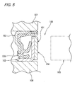
- a sensor device As a sensor device provided on the sealing device, there is a sensor device as is shown in Fig. 5 , for example, which includes a metal core 103 which is fixed to an inner circumference of an outer ring 107, which is a fixed ring, a sealing main body 106 which is attached to an inner circumferential side of the metal core 103, a magnetic encoder 101 made up of a metallic slinger 102 which is fixed to an outer circumference of an inner ring 108, which is a rotating ring, and an annular magnetized member 104 which is bonded to an outer (a right-hand side in Fig.
- the slinger 102 and the magnetized member 104 are bonded together by a phenol resin based adhesive or an epoxy resin based adhesive.
- the magnetic encoder 101 can bear stress that is produced by a difference in thermal expansion coefficient between the slinger 102 and the magnetized member 104 in a range from -40°C to 120°C which is regarded generally as a severe temperature environment, and the magnetized member 104 can be prevented from being separated from the slinger 102, for example.
- the magnetic encoder 101 cannot bear stress produced by the difference in thermal expansion coefficient under an environment severer than the aforesaid temperature environment, and the magnetized member 104 is separated from the slinger 102, leading to a problem that the magnetic encoder 101 cannot be used.
- the invention has been made in view of the problem, and an object thereof is to provide a magnetic encoder which can prevent a magnetized member from being separated from a fixed member to which the magnetized member is fixed under a severe temperature environment and a bearing to which the magnetic encoder is assembled.
- magnetic encoders are made by integrating a magnetized member which is molded by mixing magnetic powder into a resin matrix into a surface of a slinger of a sealing device via a silicone based adhesive film. Normally, the thickness of an adhesive film is preferably made thinner in order to make the adhesive force of an adhesive higher.
- an optimum using condition of adhesives is to use a silicone resin based adhesive with the thickness of an adhesive film falling in a range from 50 ⁇ m or more to 100 ⁇ m or less.
- a thermal shock test has been carried out to study the durability of silicone resin based adhesives against thermal shocks (150°C to -40°C) in the optimum using condition. Although details of this test will be shown in the example, which will be described later, it has been verified that the silicone resin based adhesives have sufficient thermal shock resistance under the optimum using condition (the thickness of an adhesive film is 50 ⁇ m or more and 100 ⁇ m or less).
- a magnetic encoder comprising a fixed member which is fixed to a rotating member and a magnetized member which is attached to the fixed member, characterized in that the magnetized member is bonded to the fixed member with a silicone resin based adhesive, and in that a thickness of an adhesive film of the silicone resin based adhesive is 50 ⁇ m or more and 100 ⁇ m or less.
- a rolling bearing comprising an inner ring on which a wheel of a vehicle is mounted, an outer ring provided so as to fit on the inner ring, a plurality of rolling elements provided between the inner ring and the outer ring, and an annular sealing device provided at an axial end portion for sealing an annular space between the inner ring and the outer ring, characterized in that the sealing device comprises a metal core fitted in the outer ring so as to be secured thereto and an annular slinger fitted on the inner ring so as to be secured thereto and comprises further a magnetic encoder which is made by integrating a magnetized member which is molded by mixing powder of a magnetic material into a resin matrix into a surface of the slinger via a silicone based adhesive film.
- the magnetized member is bonded to the fixed member by the silicone resin base adhesive and the thickness of the adhesive film of the silicone resin based adhesive is 50 ⁇ m or more and 100 ⁇ m or less, compared with the conventional case in which the silicone resin based adhesive is not used in that condition, stress produced by a difference in thermal expansion coefficient between the fixed member and the magnetized member under the severe environment can be borne, thereby making it possible to prevent the magnetized member being separated from the fixed member.
- an adhesive surface of the fixed member with the magnetized member may be worked to be roughened. According to this configuration, the adhesive enters the roughened surface of the fixed member, so that the magnetized member can be bonded more rigidly.
- the magnetized member is preferably molded by mixing magnetic powder into a resin. According to this construction, elasticity and magnetic properties of magnetized members which match applications thereof can be obtained by changing types and compositions of resins and magnetic powder.
- the rotating member may constitute an inner ring of a bearing
- the fixed member may constitute a slinger of a sealing device provided on the bearing which is fitted on the inner ring. According to the construction, in the sensor device provided on the sealing device of the bearing, the magnetized member can be prevented from being separated from the slinger.
- the magnetized member since the magnetized member is bonded to the fixed member by the silicone resin based adhesive and the thickness of the adhesive film of the silicone resin based adhesive is 50 ⁇ m or more and 100 ⁇ m or less, the magnetized member can be prevented from being separated from the fixed member to which the magnetic member is fixed under the severe temperature environment.
- the magnetized member can be prevented from being separated from the fixed member to which the magnetized member is fixed under the severe temperature environment by incorporating the magnetized member which is molded by missing the power of a magnetic material into the resin matrix into the surface of the slinger via the silicone based adhesive film.
- Fig.1 is a sectional view showing a rolling baring to which a magnetic encoder according to an embodiment of the invention is assembled.
- Fig. 2 is a sectional view showing the magnetic encoder in Fig. 1 .
- a left-right or horizontal direction is referred to as an axial direction
- an up-down or vertical direction is referred to as a diametrical direction.
- an exterior side of a sealing device is referred to as an axially outer side, and an interior side as an axially inner side.
- this rolling bearing 1 includes an inner ring 9 on which a wheel of a vehicle is mounted, an outer ring 3 which is provided so as to fit on the inner ring 9, and a plurality of or double rows of rolling elements 4, 5 provided between the inner ring 9 and the outer ring 3.
- the inner shaft 2 which is a rotating member, has a flange 2c on which a wheel-side member (not shown) is mounted at an end portion thereof which faces a vehicle's outer side (on a left-hand side in Fig. 1 ), and a small diameter portion 2d is formed on a side of the inner shaft 2 which faces a vehicle's inner side (on a right-hand side in Fig. 1 ), whereby an inner ring constituting member 6 is fitted on the small diameter portion 2d.
- the inner ring 9 is made up of the inner ring constituting member 6 and the inner shaft 2.
- An inner raceway 6a for the row of rolling elements 5 on a side facing the vehicle's inner side is formed on an outer circumferential surface of the inner ring constituting member 6.
- an inner raceway 2a for the row of rolling elements 4 on a side facing the vehicle's outer side is formed at an intermediate diameter portion 2e which is situated at an axially intermediate portion of the inner shaft 2.
- an end portion of the inner shaft 2 which faces the vehicle's inner side has a crimped portion 2f which is formed by expanding an outer circumferential side radially outwards, and this crimped portion 2f prevents the dislocation of the inner ring constituting member 6 from the inner shaft 2 so as for the inner ring constituting member 6 to be fixed to the inner shaft 2.
- the outer ring 3 is fitted on the inner ring 9 via the double rows of rolling elements 4, 5 and is provided concentrically with the inner ring 9.
- Double rows of outer raceways 3a for the double rows of rolling elements 4, 5 are formed on an inner circumferential surface of the outer ring 3.
- a flange 3c is formed on an outer circumferential surface of the outer ring 3, and by this flange 3c being attached to a vehicle body side member, not shown, the bearing is fixed to the vehicle body side member.
- the outer ring 3 is referred to as a fixed side and the inner ring 9 is referred to as a rotating side which rotates about an axis thereof.
- annular sealing devices 7 are provided at both axial end portions to seal an annular space R between the inner ring 9 and the outer ring 3.
- the sealing device shown in the sectional view of Fig. 2 is such as to be used as the sealing device on the vehicle's outer side in Fig. 1 .
- This sealing device 7 is provided between an inner circumferential surface 3b of the outer ring 3 and an outer circumferential surface 6b of the inner ring constituting member 6, so as to prevent leakage of a lubricant in an interior of the bearing which constitutes a rolling element 4, 5 side thereof and infiltration of foreign matters such as muddy water and the like into the rolling element 4, 5 side from an exterior portion of the bearing.
- the sealing device 7 includes a metal core 10 which is fitted in the outer ring 3 so as to be secured thereto and a slinger 11 which is fitted on the inner ring constituting member 6 so as to be secured thereto.
- the metal core 10 is made up of a metal core cylindrical portion 10a which is fitted in the outer ring 3 and a metal core annular portion 10c which is bent radially inwards from an axial end portion 10b of the metal core cylindrical portion 10a and has a substantially L-shaped section.
- the metal core 10 is made into an annular shape on the whole and is formed by pressing, for example, cold-rolled steel sheet such as SPCC, SPCD, SPEC or the like.
- a sealing main body 12 which is made up of an elastic member such as rubber, for example, is secured to the metal core 10 so as to be integrated with the metal core 10.
- the slinger 11 is made up of a slinger cylindrical portion 11a which is fitted on the outer circumferential surface 6b of the inner ring constituting member 6 and a slinger annular portion 11c which is bent radially outwards from the other axial end portion of the slinger cylindrical portion 11a and has an L-shaped section.
- This slinger 11 is made into an annular shape on the whole and is formed by pressing, for example, sheet metal such as stainless steel or the like.
- the sealing main body 12 has a base portion 12a which is attached to a radially inward end portion on the other axial side of the metal core annular portion 10c and includes radial lips 13 which extend from the base portion 12a in an elastically deformed condition so as to be brought into sliding contact with an outer circumferential surface of the slinger cylindrical portion 11a and an axial lip 14 which extends from the base portion 12a in an elastically deformed condition so as to be brought into sliding contact with an axially inner surface of the slinger annular portion 11c.
- the sealing device 7 is assembled so that the metal core cylindrical portion 10a of the metal core 10 faces the slinger cylindrical portion 11a of the slinger 11 and that the metal core annular portion 10c of the metal core 10 and the slinger annular portion 11c of the slinger 11.
- An annular magnetized member 15 is bonded to an axially outer surface 11d of the slinger 11 so as to be integrated into the slinger 11, and this magnetized member 15 and the slinger 11 make up a magnetic encoder 16. Then, this magnetic encoder 16 and a sensor 18 which is disposed to face the magnetized member 15 of the magnetic encoder 16 make up a sensor device 19.
- the magnetized member 15 is an annular magnet on which N poles and S poles are magnetized alternately in a circumferential direction, and a plastic magnet which is injection molded by mixing powder of a magnetic material such as a ferrite based magnet into a thermoplastic resin matrix such as a polyamide based resin or the like, a bonded magnet (a rubber magnet) which is molded by mixing powder of a magnetic material such as a neodymium based magnet into a synthetic resin matrix such as rubber or the like is used.
- magnetic encoders 16 can be formed which have heat resistances, magnetic force properties and the like according to various applications.
- the sensor 18 is made up of an eddy current displacement sensor, for example.
- the sensor 18 generates a magnetic field between the magnetic encoder 16 and itself and detects a change in a magnetic flux density of the magnetic field which corresponds to the rotation of the bearing by a detecting unit.
- the sensor 18 is designed to output the change as a detection (voltage) signal to a control unit such as an ECU or the like of a vehicle, which is not shown.
- the slinger 11 and the magnetized member 15 are bonded together at an adhesive surface 17 with a silicone based adhesive.
- the silicone based adhesive is an adhesive which uses a thermoplastic resin such as organopolysiloxane or the like as a principal constituent.
- the silicone based adhesive since the silicone based adhesive has superior heat resistance and freeze resistance and is made into an rubber-like elastic substance when it sets, the silicone adhesive can be used to bond a target material for bonding which has a large thermal expansion coefficient difference and which generates large shearing stress.
- a thickness of an adhesive film of the silicone based adhesive is optimally 50 ⁇ m or more and 100 ⁇ m or less when considering thermal shock resistance. The grounds for the optimal condition will be described in the following example.
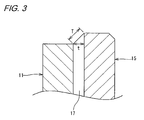
- Fig. 3 is a sectional view showing a thickness of the adhesive film of the silicone resin based adhesive when a thermal deformation occurs.
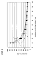
- Fig. 4 is a graph showing a relationship between thickness and elongation of an adhesive film of a silicone resin based adhesive.
- a thermal shock test was carried out to verify the durability against thermal shock of the silicone resin based adhesive according to the invention under the optimum using condition (the adhesive layer thickness is 50 ⁇ m or more and 100 ⁇ m or less).
- the adhesive layer thickness is 50 ⁇ m or more and 100 ⁇ m or less.
- adhesives were treated at 150°C for 10 minutes, and thereafter, thermal shock was applied to the adhesives by repeating a high-temperature treatment and a low-temperature treatment as a treatment at -40°C for 10 minutes being referred to as one cycle, so as to verify the numbers of cycles that the adhesives could bear.
- the following adhesives were used as examples and a comparison example.
- Example 1 Silicone resin based adhesive (TSE 322 by GE Toshiba Inc.)
- Example 2 Silicone resin based adhesive (TSE3280-G by GE Toshiba Inc.)
- Example 3 Silicone resin based adhesive (KE-347 by Shinetsu Silicone Company Ltd.)
- Comparison Example 1 Phenol resin based adhesive (C-12 by Tokyo Chemical Company Ltd.) The results of the test are shown in Table 1.
- the silicone resin based adhesives have sufficient thermal shock resistances under the optimum using condition (the adhesive layer thickness is 50 ⁇ m or more and 100 ⁇ m or less).
- the magnetic encoder 16 of the invention can also be assembled to other vehicle rolling bearings than the rolling bearing 1 exemplified in the embodiment which include, for example, a tapered roller bearing and a straight roller bearing.
- the application of the magnetic encoder of the invention is not limited to vehicles. It is also applicable to bearing devices in general-use machineries.
- the magnetized member 15 is described as being bonded only to the axially outer surface 11d, the magnetized member 15 may be bonded from a radially outer end portion to the axially outer surface 11d of the slinger annular portion 11c.
Landscapes
- Engineering & Computer Science (AREA)
- General Engineering & Computer Science (AREA)
- Mechanical Engineering (AREA)
- Physics & Mathematics (AREA)
- General Physics & Mathematics (AREA)
- Transmission And Conversion Of Sensor Element Output (AREA)
- Rolling Contact Bearings (AREA)
Abstract
Description
- The present invention relates to a magnetic encoder for use in detecting a rotating condition of a wheel or the like and a bearing to which the same magnetic encoder is assembled.
- As a rolling bearing on which a wheel of a vehicle such as a motor vehicle is mounted, there is, for example, a rolling bearing which includes an outer ring and an inner ring which is provided on the outer ring via rolling elements. In addition, a sensor device for detecting a rotating speed of a wheel is used to control an anti-lock braking system (ABS) of a motor vehicle, and there is known a configuration in which the sensor device is mounted on a sealing device for sealing an annular space between the outer ring and the inner ring so as to be integrated into the sealing device to thereby realize miniaturization of the sensor device.
- As a sensor device provided on the sealing device, there is a sensor device as is shown in
Fig. 5 , for example, which includes ametal core 103 which is fixed to an inner circumference of anouter ring 107, which is a fixed ring, a sealingmain body 106 which is attached to an inner circumferential side of themetal core 103, amagnetic encoder 101 made up of ametallic slinger 102 which is fixed to an outer circumference of aninner ring 108, which is a rotating ring, and an annular magnetizedmember 104 which is bonded to an outer (a right-hand side inFig. 5 ) and on which N poles and S poles are magnetized alternately in a circumferential direction, and asensor 105 which is disposed to face themagnetic encoder 101. In this sensor device, a rotating speed of a wheel is detected by the sensor 105 a change in magnetic flux generated by rotation of themagnetic encoder 101 together with the inner ring 108 (for example, refer toPatent Documents 1, 2). -
- Patent Document 1:
JP-A-2006-90956 - Patent Document 2:
JP-A-2006-90995 - In the conventional
magnetic encoder 101 described above, theslinger 102 and themagnetized member 104 are bonded together by a phenol resin based adhesive or an epoxy resin based adhesive. In this case, themagnetic encoder 101 can bear stress that is produced by a difference in thermal expansion coefficient between theslinger 102 and the magnetizedmember 104 in a range from -40°C to 120°C which is regarded generally as a severe temperature environment, and themagnetized member 104 can be prevented from being separated from theslinger 102, for example.
However, themagnetic encoder 101 cannot bear stress produced by the difference in thermal expansion coefficient under an environment severer than the aforesaid temperature environment, and themagnetized member 104 is separated from theslinger 102, leading to a problem that themagnetic encoder 101 cannot be used. - The invention has been made in view of the problem, and an object thereof is to provide a magnetic encoder which can prevent a magnetized member from being separated from a fixed member to which the magnetized member is fixed under a severe temperature environment and a bearing to which the magnetic encoder is assembled.
- The inventors have studied conditions in which adhesives are used which are used in magnetic encoders in order to attain the object. The inventor and others have paid attention to the fact that in rolling bearings, magnetic encoders are made by integrating a magnetized member which is molded by mixing magnetic powder into a resin matrix into a surface of a slinger of a sealing device via a silicone based adhesive film. Normally, the thickness of an adhesive film is preferably made thinner in order to make the adhesive force of an adhesive higher. However, as a result of studies made on the adaptability to shearing stress at the time of thermal expansion, as will be shown in an example which will be described later, it has been implied that an optimum using condition of adhesives is to use a silicone resin based adhesive with the thickness of an adhesive film falling in a range from 50 µm or more to 100 µm or less.
In addition, a thermal shock test has been carried out to study the durability of silicone resin based adhesives against thermal shocks (150°C to -40°C) in the optimum using condition. Although details of this test will be shown in the example, which will be described later, it has been verified that the silicone resin based adhesives have sufficient thermal shock resistance under the optimum using condition (the thickness of an adhesive film is 50 µm or more and 100 µm or less). - Based on the result above, with a view to attaining the object, according to the invention, there is provided a magnetic encoder comprising a fixed member which is fixed to a rotating member and a magnetized member which is attached to the fixed member, characterized in that the magnetized member is bonded to the fixed member with a silicone resin based adhesive, and in that a thickness of an adhesive film of the silicone resin based adhesive is 50 µm or more and 100 µm or less.
Further, according to the invention, there is provided a rolling bearing comprising an inner ring on which a wheel of a vehicle is mounted, an outer ring provided so as to fit on the inner ring, a plurality of rolling elements provided between the inner ring and the outer ring, and an annular sealing device provided at an axial end portion for sealing an annular space between the inner ring and the outer ring, characterized in that
the sealing device comprises a metal core fitted in the outer ring so as to be secured thereto and an annular slinger fitted on the inner ring so as to be secured thereto and comprises further
a magnetic encoder which is made by integrating a magnetized member which is molded by mixing powder of a magnetic material into a resin matrix into a surface of the slinger via a silicone based adhesive film.
In the magnetic encoder of the invention, since the magnetized member is bonded to the fixed member by the silicone resin base adhesive and the thickness of the adhesive film of the silicone resin based adhesive is 50 µm or more and 100 µm or less, compared with the conventional case in which the silicone resin based adhesive is not used in that condition, stress produced by a difference in thermal expansion coefficient between the fixed member and the magnetized member under the severe environment can be borne, thereby making it possible to prevent the magnetized member being separated from the fixed member. - In addition, an adhesive surface of the fixed member with the magnetized member may be worked to be roughened. According to this configuration, the adhesive enters the roughened surface of the fixed member, so that the magnetized member can be bonded more rigidly.
- Additionally, the magnetized member is preferably molded by mixing magnetic powder into a resin. According to this construction, elasticity and magnetic properties of magnetized members which match applications thereof can be obtained by changing types and compositions of resins and magnetic powder.
- In addition, the rotating member may constitute an inner ring of a bearing, and the fixed member may constitute a slinger of a sealing device provided on the bearing which is fitted on the inner ring. According to the construction, in the sensor device provided on the sealing device of the bearing, the magnetized member can be prevented from being separated from the slinger.
- According to the magnetic encoder of the invention, since the magnetized member is bonded to the fixed member by the silicone resin based adhesive and the thickness of the adhesive film of the silicone resin based adhesive is 50 µm or more and 100 µm or less, the magnetized member can be prevented from being separated from the fixed member to which the magnetic member is fixed under the severe temperature environment.
In addition, according to the rolling bearing of the invention, the magnetized member can be prevented from being separated from the fixed member to which the magnetized member is fixed under the severe temperature environment by incorporating the magnetized member which is molded by missing the power of a magnetic material into the resin matrix into the surface of the slinger via the silicone based adhesive film. -
- [
Fig. 1 ] A sectional view showing a rolling bearing to which a magnetic encoder according to an embodiment of the invention is assembled. - [
Fig. 2 ] A sectional view showing the magnetic encoder inFig. 1 . - [
Fig. 3 ] A sectional view showing a thickness of an adhesive film of a silicone resin base adhesive when a thermal deformation occurs. - [
Fig. 4 ] A graph showing a relationship between thickness and elongation of a silicone resin based adhesive. - [
Fig. 5 ] A sectional view showing a conventional magnetic encoder. - Hereinafter, referring to the drawings, an embodiment of a magnetic encoder and a rolling bearing of the invention will be described.
Fig.1 is a sectional view showing a rolling baring to which a magnetic encoder according to an embodiment of the invention is assembled.Fig. 2 is a sectional view showing the magnetic encoder inFig. 1 . Note that in these drawings, a left-right or horizontal direction is referred to as an axial direction, and an up-down or vertical direction is referred to as a diametrical direction. In addition, as has been described previously, an exterior side of a sealing device is referred to as an axially outer side, and an interior side as an axially inner side. - As shown in
Fig. 1 , this rollingbearing 1 includes aninner ring 9 on which a wheel of a vehicle is mounted, anouter ring 3 which is provided so as to fit on theinner ring 9, and a plurality of or double rows ofrolling elements inner ring 9 and theouter ring 3. - In addition, the
inner shaft 2, which is a rotating member, has aflange 2c on which a wheel-side member (not shown) is mounted at an end portion thereof which faces a vehicle's outer side (on a left-hand side inFig. 1 ), and asmall diameter portion 2d is formed on a side of theinner shaft 2 which faces a vehicle's inner side (on a right-hand side inFig. 1 ), whereby an innerring constituting member 6 is fitted on thesmall diameter portion 2d. Theinner ring 9 is made up of the innerring constituting member 6 and theinner shaft 2. Aninner raceway 6a for the row ofrolling elements 5 on a side facing the vehicle's inner side is formed on an outer circumferential surface of the innerring constituting member 6. In addition, aninner raceway 2a for the row ofrolling elements 4 on a side facing the vehicle's outer side is formed at anintermediate diameter portion 2e which is situated at an axially intermediate portion of theinner shaft 2. Further, an end portion of theinner shaft 2 which faces the vehicle's inner side has a crimpedportion 2f which is formed by expanding an outer circumferential side radially outwards, and this crimpedportion 2f prevents the dislocation of the innerring constituting member 6 from theinner shaft 2 so as for the innerring constituting member 6 to be fixed to theinner shaft 2. - The
outer ring 3 is fitted on theinner ring 9 via the double rows ofrolling elements inner ring 9. Double rows ofouter raceways 3a for the double rows ofrolling elements outer ring 3. Aflange 3c is formed on an outer circumferential surface of theouter ring 3, and by thisflange 3c being attached to a vehicle body side member, not shown, the bearing is fixed to the vehicle body side member. Namely, theouter ring 3 is referred to as a fixed side and theinner ring 9 is referred to as a rotating side which rotates about an axis thereof. In addition,annular sealing devices 7 are provided at both axial end portions to seal an annular space R between theinner ring 9 and theouter ring 3. - The sealing device shown in the sectional view of
Fig. 2 is such as to be used as the sealing device on the vehicle's outer side inFig. 1 . Thissealing device 7 is provided between an innercircumferential surface 3b of theouter ring 3 and an outercircumferential surface 6b of the innerring constituting member 6, so as to prevent leakage of a lubricant in an interior of the bearing which constitutes arolling element rolling element sealing device 7 includes ametal core 10 which is fitted in theouter ring 3 so as to be secured thereto and aslinger 11 which is fitted on the innerring constituting member 6 so as to be secured thereto. - The
metal core 10 is made up of a metal corecylindrical portion 10a which is fitted in theouter ring 3 and a metal coreannular portion 10c which is bent radially inwards from anaxial end portion 10b of the metal corecylindrical portion 10a and has a substantially L-shaped section. Themetal core 10 is made into an annular shape on the whole and is formed by pressing, for example, cold-rolled steel sheet such as SPCC, SPCD, SPEC or the like. In addition, a sealingmain body 12 which is made up of an elastic member such as rubber, for example, is secured to themetal core 10 so as to be integrated with themetal core 10. - The
slinger 11 is made up of a slingercylindrical portion 11a which is fitted on the outercircumferential surface 6b of the innerring constituting member 6 and a slingerannular portion 11c which is bent radially outwards from the other axial end portion of the slingercylindrical portion 11a and has an L-shaped section. Thisslinger 11 is made into an annular shape on the whole and is formed by pressing, for example, sheet metal such as stainless steel or the like. - The sealing
main body 12 has abase portion 12a which is attached to a radially inward end portion on the other axial side of the metal coreannular portion 10c and includes radial lips 13 which extend from thebase portion 12a in an elastically deformed condition so as to be brought into sliding contact with an outer circumferential surface of the slingercylindrical portion 11a and anaxial lip 14 which extends from thebase portion 12a in an elastically deformed condition so as to be brought into sliding contact with an axially inner surface of the slingerannular portion 11c.
In addition, thesealing device 7 is assembled so that the metal corecylindrical portion 10a of themetal core 10 faces the slingercylindrical portion 11a of theslinger 11 and that the metal coreannular portion 10c of themetal core 10 and the slingerannular portion 11c of theslinger 11. - An annular
magnetized member 15 is bonded to an axiallyouter surface 11d of theslinger 11 so as to be integrated into theslinger 11, and thismagnetized member 15 and theslinger 11 make up amagnetic encoder 16. Then, thismagnetic encoder 16 and asensor 18 which is disposed to face themagnetized member 15 of themagnetic encoder 16 make up asensor device 19. - The
magnetized member 15 is an annular magnet on which N poles and S poles are magnetized alternately in a circumferential direction, and a plastic magnet which is injection molded by mixing powder of a magnetic material such as a ferrite based magnet into a thermoplastic resin matrix such as a polyamide based resin or the like, a bonded magnet (a rubber magnet) which is molded by mixing powder of a magnetic material such as a neodymium based magnet into a synthetic resin matrix such as rubber or the like is used. By changing types and mixing compositions of these resins and magnet powders,magnetic encoders 16 can be formed which have heat resistances, magnetic force properties and the like according to various applications. - The
sensor 18 is made up of an eddy current displacement sensor, for example. Thesensor 18 generates a magnetic field between themagnetic encoder 16 and itself and detects a change in a magnetic flux density of the magnetic field which corresponds to the rotation of the bearing by a detecting unit. In addition, thesensor 18 is designed to output the change as a detection (voltage) signal to a control unit such as an ECU or the like of a vehicle, which is not shown. - In the
magnetic encoder 16 of the embodiment, theslinger 11 and themagnetized member 15 are bonded together at anadhesive surface 17 with a silicone based adhesive. The silicone based adhesive is an adhesive which uses a thermoplastic resin such as organopolysiloxane or the like as a principal constituent. In addition, since the silicone based adhesive has superior heat resistance and freeze resistance and is made into an rubber-like elastic substance when it sets, the silicone adhesive can be used to bond a target material for bonding which has a large thermal expansion coefficient difference and which generates large shearing stress.
In addition, a thickness of an adhesive film of the silicone based adhesive is optimally 50 µm or more and 100 µm or less when considering thermal shock resistance. The grounds for the optimal condition will be described in the following example. - In addition, since the axially
outer surface 11d of the slingerannular portion 11c which constitutes the adhesive surface of theslinger 11 with themagnetized member 15 is worked to be roughened through shot peening, for example, the adhesive force by the silicone based adhesive is strengthened further. -
Fig. 3 is a sectional view showing a thickness of the adhesive film of the silicone resin based adhesive when a thermal deformation occurs. In addition,Fig. 4 is a graph showing a relationship between thickness and elongation of an adhesive film of a silicone resin based adhesive.
With a view to attaining the object of the invention, the adaptability of adhesives to shearing stress or elongations of adhesives at the time of thermal expansion have been verified.
As is show inFig. 3 , the test was carried out with amagnetized member 15 bonded to theslinger 11 with a silicone resin based adhesive and elongations (%) of adhesives were calculated by the following calculation formula with a length of a gradient of an adhesive at the time of thermal expansion defined as T and a thickness of an adhesive film as t. In addition, TSE 322 made by GE Toshiba Inc. was used as a silicone resin based adhesive.
In addition, the details of line graphs (a to e) are as follows. - a: a temperature change from 25°C to 150°C
- b: a temperature change from 25°C to 140°C
- c: a temperature change from 25°C to 130°C
- d: a temperature change from 25°C to 120°C
- e: a temperature change from 25°C to -40°C
- Next, a thermal shock test was carried out to verify the durability against thermal shock of the silicone resin based adhesive according to the invention under the optimum using condition (the adhesive layer thickness is 50 µm or more and 100 µm or less).
As a test condition, adhesives were treated at 150°C for 10 minutes, and thereafter, thermal shock was applied to the adhesives by repeating a high-temperature treatment and a low-temperature treatment as a treatment at -40°C for 10 minutes being referred to as one cycle, so as to verify the numbers of cycles that the adhesives could bear. The following adhesives were used as examples and a comparison example.
Example 1: Silicone resin based adhesive (TSE 322 by GE Toshiba Inc.)
Example 2: Silicone resin based adhesive (TSE3280-G by GE Toshiba Inc.)
Example 3: Silicone resin based adhesive (KE-347 by Shinetsu Silicone Company Ltd.)
Comparison Example 1: Phenol resin based adhesive (C-12 by Tokyo Chemical Company Ltd.)
The results of the test are shown in Table 1. - [Table 1]
- Thermal shock test results (150°
C 10 min <-> -40°C 10 min) - Example 1: 1015 cycles, no problem occurred
- Example 2: 1015 cycles, no problem occurred
- Example 3: 1015 cycles, no problem occurred
- Comparison Example 1: 421 to 890 cycles, cracks generated
- Example 1: Silicone resin based adhesive (TSE 322 by GE Toshiba Inc.)
- Example 2: Silicone resin based adhesive (TSE3280-G by GE Toshiba Inc.)
- Example 3: Silicone resin based adhesive (KE-347 by Shinetsu Silicone Company Ltd.) Comparison Example 1: Phenol resin based adhesive (C-12 by Tokyo Chemical Company Ltd.)
- It is verified from the results shown in Table 1 that compared with the conventional phenol resin based adhesive, the silicone resin based adhesives have sufficient thermal shock resistances under the optimum using condition (the adhesive layer thickness is 50 µm or more and 100 µm or less).
- In addition, the
magnetic encoder 16 of the invention can also be assembled to other vehicle rolling bearings than the rollingbearing 1 exemplified in the embodiment which include, for example, a tapered roller bearing and a straight roller bearing. In addition, the application of the magnetic encoder of the invention is not limited to vehicles. It is also applicable to bearing devices in general-use machineries. In addition, although themagnetized member 15 is described as being bonded only to the axiallyouter surface 11d, themagnetized member 15 may be bonded from a radially outer end portion to the axiallyouter surface 11d of the slingerannular portion 11c.
As is shown in
Consequently, an optimum using condition in which the silicone resin based adhesive according to the invention bears shearing stress at the time of thermal expansion is implied to occur when the adhesive layer thickness is 50 µm or more and 100 µm or less.
Claims (7)
- A magnetic encoder comprising a fixed member which is fixed to a rotating member and a magnetized member which is attached to the fixed member, whereinthe magnetized member is bonded to the fixed member with a silicone resin based adhesive, anda thickness of an adhesive layer of the silicone resin based adhesive is 50 µm or more and 100 µm or less.
- A magnetic encoder as set forth in Claim 1, wherein
an adhesive surface of the fixed member with the magnetized member is worked to be roughened. - A magnetic encoder as set forth in Claim 1, wherein the magnetized member is molded by mixing a magnetic powder in a resin.
- A magnetic encoder as set forth in Claim 1, wherein
the rotating member is an inner ring of a bearing, and the fixed member is a slinger of a sealing device provided on the bearing which is fitted on the inner ring. - A rolling bearing comprising an inner ring on which a wheel of a vehicle is mounted, an outer ring provided so as to fit on the inner ring, a plurality of rolling elements provided between the inner ring and the outer ring, and an annular sealing device provided at an axial end portion for sealing an annular space between the inner ring and the outer ring, wherein
the sealing device comprises a metal core fitted in the outer ring so as to be secured thereto and an annular slinger fitted on the inner ring so as to be secured thereto, and comprises further
a magnetic encoder which is made by integrating a magnetized member which is molded by mixing a powder of a magnetic material into a resin matrix into a surface of the slinger via a silicone based adhesive layer. - A rolling bearing as set forth in Claim 5, wherein the adhesive layer thickness of the silicone resin based adhesive is 50 µm or more and 100 µm or less.
- A rolling bearing as set forth in Claim 5, wherein the slinger comprises a slinger cylindrical portion which is fitted on an outer circumferential surface of the inner ring and a slinger annular portion which is bent radially outwards from an axial end portion of the slinger cylindrical portion, and in that the magnetized member is bonded to an axially outer surface of the slinger.
Applications Claiming Priority (2)
| Application Number | Priority Date | Filing Date | Title |
|---|---|---|---|
| JP2007176589A JP4859772B2 (en) | 2007-07-04 | 2007-07-04 | Magnetic encoder |
| PCT/JP2008/062074 WO2009005127A1 (en) | 2007-07-04 | 2008-07-03 | Magnetic encoder and rolling bearing |
Publications (3)
| Publication Number | Publication Date |
|---|---|
| EP2163857A1 true EP2163857A1 (en) | 2010-03-17 |
| EP2163857A4 EP2163857A4 (en) | 2012-09-26 |
| EP2163857B1 EP2163857B1 (en) | 2014-09-10 |
Family
ID=40226168
Family Applications (1)
| Application Number | Title | Priority Date | Filing Date |
|---|---|---|---|
| EP08777826.2A Not-in-force EP2163857B1 (en) | 2007-07-04 | 2008-07-03 | Magnetic encoder and rolling bearing |
Country Status (5)
| Country | Link |
|---|---|
| US (1) | US8313241B2 (en) |
| EP (1) | EP2163857B1 (en) |
| JP (1) | JP4859772B2 (en) |
| CN (1) | CN101688792B (en) |
| WO (1) | WO2009005127A1 (en) |
Cited By (1)
| Publication number | Priority date | Publication date | Assignee | Title |
|---|---|---|---|---|
| EP3104031A1 (en) * | 2015-06-10 | 2016-12-14 | MAHLE International GmbH | Sliding element comprising a flexible adhesive |
Families Citing this family (4)
| Publication number | Priority date | Publication date | Assignee | Title |
|---|---|---|---|---|
| DE102011004706A1 (en) * | 2011-02-25 | 2012-08-30 | Schaeffler Technologies Gmbh & Co. Kg | Tapered roller bearing with cage |
| JP2016038294A (en) * | 2014-08-07 | 2016-03-22 | 日本電産サンキョー株式会社 | Magnetic linear encoder |
| KR101931283B1 (en) * | 2017-06-07 | 2018-12-21 | 현대 파워텍 주식회사 | Assembly of sleeve for transmission |
| JP7441099B2 (en) * | 2020-03-31 | 2024-02-29 | ミネベアミツミ株式会社 | absolute encoder |
Family Cites Families (15)
| Publication number | Priority date | Publication date | Assignee | Title |
|---|---|---|---|---|
| US6637754B1 (en) * | 1999-11-17 | 2003-10-28 | Ntn Corporation | Wheel bearing and sealing device therefor |
| JP2003222150A (en) * | 2002-01-31 | 2003-08-08 | Ntn Corp | Magnetic encoder and bearing for wheel provided with it |
| JP2004053410A (en) * | 2002-07-19 | 2004-02-19 | Uchiyama Mfg Corp | Magnetic encoder |
| JP4135079B2 (en) * | 2002-12-19 | 2008-08-20 | 東洋紡績株式会社 | Transparent conductive film, method for producing transparent conductive sheet, and touch panel |
| US20050007226A1 (en) * | 2003-05-22 | 2005-01-13 | Uchiyama Manufacturing Corp. | Magnetic encoder |
| EP2865999B1 (en) | 2004-01-22 | 2018-08-22 | NSK Ltd. | Magnetic encoder and bearing |
| CN100567904C (en) * | 2004-01-22 | 2009-12-09 | 日本精工株式会社 | Magnetic encoders and bearings |
| JP4178412B2 (en) * | 2004-08-23 | 2008-11-12 | 日本精工株式会社 | Magnetic encoder, method of manufacturing the same, and rolling bearing unit |
| JP2005321307A (en) * | 2004-05-10 | 2005-11-17 | Nsk Ltd | Magnetic encoder and rolling bearing unit including the magnetic encoder |
| JP4586475B2 (en) | 2004-09-27 | 2010-11-24 | 日本精工株式会社 | Magnetic encoder |
| JP4639955B2 (en) * | 2005-05-25 | 2011-02-23 | 日本精工株式会社 | Magnetic encoder and rolling bearing unit including the magnetic encoder |
| EP1881300B3 (en) * | 2005-05-10 | 2021-12-15 | NSK Ltd. | Magnetic encoder and rolling bearing unit comprising magnetic encoder |
| JP4899404B2 (en) * | 2005-10-05 | 2012-03-21 | 日本精工株式会社 | Rolling bearing with encoder |
| EP1798558B1 (en) * | 2005-12-16 | 2013-05-01 | JTEKT Corporation | Magnetized pulser ring |
| CN100390505C (en) * | 2006-01-20 | 2008-05-28 | 安徽金海迪尔信息技术有限责任公司 | Absolute Multiturn Magnetic Encoder |
-
2007
- 2007-07-04 JP JP2007176589A patent/JP4859772B2/en not_active Expired - Fee Related
-
2008
- 2008-07-03 CN CN2008800233165A patent/CN101688792B/en not_active Expired - Fee Related
- 2008-07-03 WO PCT/JP2008/062074 patent/WO2009005127A1/en not_active Ceased
- 2008-07-03 US US12/452,396 patent/US8313241B2/en not_active Expired - Fee Related
- 2008-07-03 EP EP08777826.2A patent/EP2163857B1/en not_active Not-in-force
Cited By (1)
| Publication number | Priority date | Publication date | Assignee | Title |
|---|---|---|---|---|
| EP3104031A1 (en) * | 2015-06-10 | 2016-12-14 | MAHLE International GmbH | Sliding element comprising a flexible adhesive |
Also Published As
| Publication number | Publication date |
|---|---|
| US20100104230A1 (en) | 2010-04-29 |
| US8313241B2 (en) | 2012-11-20 |
| EP2163857B1 (en) | 2014-09-10 |
| CN101688792A (en) | 2010-03-31 |
| WO2009005127A1 (en) | 2009-01-08 |
| EP2163857A4 (en) | 2012-09-26 |
| CN101688792B (en) | 2012-07-18 |
| JP2009014509A (en) | 2009-01-22 |
| JP4859772B2 (en) | 2012-01-25 |
Similar Documents
| Publication | Publication Date | Title |
|---|---|---|
| US8360649B2 (en) | Wheel bearing apparatus incorporated with a wheel speed detecting apparatus | |
| US8052329B2 (en) | Wheel bearing apparatus incorporated with a wheel speed detecting apparatus | |
| US8174257B2 (en) | Wheel bearing device with rotation detector | |
| EP1965090B1 (en) | Magnetized pulsar ring, and rolling bearing device with sensor using the same | |
| US7692422B2 (en) | Bearing assembly having rotation sensor and mounting structure to support sensor cap and connector | |
| US7800361B2 (en) | Magnetic encoder | |
| CN100497974C (en) | Rolling bearing unit with rotating speed-detecting device | |
| US7731427B2 (en) | Wheel bearing apparatus incorporated with a wheel speed detecting apparatus and method of its assembly | |
| EP2163857B1 (en) | Magnetic encoder and rolling bearing | |
| US8303186B2 (en) | Wheel bearing apparatus incorporated with a wheel speed detecting apparatus | |
| JP2002333033A (en) | Wheel bearings | |
| WO2008059788A1 (en) | Sensor-equipped sealing device, and rolling bearing device adapted for use in vehicle and using the sealing device | |
| EP2045101B1 (en) | Bearing device for drive wheel | |
| WO2005040647A1 (en) | Seal device with sensor and rolling bearing device using the seal device | |
| EP2078935A1 (en) | Magnetized pulsar ring and rolling bearing unit with sensor equipped therewith | |
| JP5061652B2 (en) | Magnetized pulsar ring and sensor-equipped rolling bearing device using the same | |
| CN101646946B (en) | Sensor holder, and bearing device adapted for use for wheel, having rotation speed detection device, and integral with the sensor holder | |
| JP4899404B2 (en) | Rolling bearing with encoder | |
| JP2008224228A (en) | Magnetized pulsar ring fixing structure and rolling bearing device with sensor using the same | |
| JP2009036335A (en) | Wheel bearing device with rotating speed detection device | |
| JP2008303900A (en) | Wheel bearing device with rotational speed detector | |
| JP2009002385A (en) | Wheel bearing device with rotational speed detector | |
| JP2007010344A (en) | Magnetic encoder, method for manufacturing the same, and vehicle bearing provided with the magnetic encoder | |
| JP5286674B2 (en) | Rolling bearing device with sensor | |
| JP2009257872A (en) | Magnetized pulser ring and roller bearing device using the same |
Legal Events
| Date | Code | Title | Description |
|---|---|---|---|
| PUAI | Public reference made under article 153(3) epc to a published international application that has entered the european phase |
Free format text: ORIGINAL CODE: 0009012 |
|
| 17P | Request for examination filed |
Effective date: 20091223 |
|
| AK | Designated contracting states |
Kind code of ref document: A1 Designated state(s): AT BE BG CH CY CZ DE DK EE ES FI FR GB GR HR HU IE IS IT LI LT LU LV MC MT NL NO PL PT RO SE SI SK TR |
|
| AX | Request for extension of the european patent |
Extension state: AL BA MK RS |
|
| DAX | Request for extension of the european patent (deleted) | ||
| A4 | Supplementary search report drawn up and despatched |
Effective date: 20120827 |
|
| RIC1 | Information provided on ipc code assigned before grant |
Ipc: F16C 41/00 20060101ALI20120821BHEP Ipc: G01P 3/487 20060101ALI20120821BHEP Ipc: G01D 5/245 20060101AFI20120821BHEP |
|
| 17Q | First examination report despatched |
Effective date: 20130405 |
|
| GRAP | Despatch of communication of intention to grant a patent |
Free format text: ORIGINAL CODE: EPIDOSNIGR1 |
|
| INTG | Intention to grant announced |
Effective date: 20140409 |
|
| GRAS | Grant fee paid |
Free format text: ORIGINAL CODE: EPIDOSNIGR3 |
|
| GRAA | (expected) grant |
Free format text: ORIGINAL CODE: 0009210 |
|
| AK | Designated contracting states |
Kind code of ref document: B1 Designated state(s): AT BE BG CH CY CZ DE DK EE ES FI FR GB GR HR HU IE IS IT LI LT LU LV MC MT NL NO PL PT RO SE SI SK TR |
|
| REG | Reference to a national code |
Ref country code: GB Ref legal event code: FG4D |
|
| REG | Reference to a national code |
Ref country code: CH Ref legal event code: EP |
|
| REG | Reference to a national code |
Ref country code: IE Ref legal event code: FG4D |
|
| REG | Reference to a national code |
Ref country code: AT Ref legal event code: REF Ref document number: 686927 Country of ref document: AT Kind code of ref document: T Effective date: 20141015 |
|
| REG | Reference to a national code |
Ref country code: DE Ref legal event code: R096 Ref document number: 602008034359 Country of ref document: DE Effective date: 20141023 |
|
| PG25 | Lapsed in a contracting state [announced via postgrant information from national office to epo] |
Ref country code: FI Free format text: LAPSE BECAUSE OF FAILURE TO SUBMIT A TRANSLATION OF THE DESCRIPTION OR TO PAY THE FEE WITHIN THE PRESCRIBED TIME-LIMIT Effective date: 20140910 Ref country code: NO Free format text: LAPSE BECAUSE OF FAILURE TO SUBMIT A TRANSLATION OF THE DESCRIPTION OR TO PAY THE FEE WITHIN THE PRESCRIBED TIME-LIMIT Effective date: 20141210 Ref country code: ES Free format text: LAPSE BECAUSE OF FAILURE TO SUBMIT A TRANSLATION OF THE DESCRIPTION OR TO PAY THE FEE WITHIN THE PRESCRIBED TIME-LIMIT Effective date: 20140910 Ref country code: LT Free format text: LAPSE BECAUSE OF FAILURE TO SUBMIT A TRANSLATION OF THE DESCRIPTION OR TO PAY THE FEE WITHIN THE PRESCRIBED TIME-LIMIT Effective date: 20140910 Ref country code: SE Free format text: LAPSE BECAUSE OF FAILURE TO SUBMIT A TRANSLATION OF THE DESCRIPTION OR TO PAY THE FEE WITHIN THE PRESCRIBED TIME-LIMIT Effective date: 20140910 Ref country code: GR Free format text: LAPSE BECAUSE OF FAILURE TO SUBMIT A TRANSLATION OF THE DESCRIPTION OR TO PAY THE FEE WITHIN THE PRESCRIBED TIME-LIMIT Effective date: 20141211 |
|
| REG | Reference to a national code |
Ref country code: NL Ref legal event code: VDEP Effective date: 20140910 |
|
| REG | Reference to a national code |
Ref country code: LT Ref legal event code: MG4D |
|
| PG25 | Lapsed in a contracting state [announced via postgrant information from national office to epo] |
Ref country code: HR Free format text: LAPSE BECAUSE OF FAILURE TO SUBMIT A TRANSLATION OF THE DESCRIPTION OR TO PAY THE FEE WITHIN THE PRESCRIBED TIME-LIMIT Effective date: 20140910 Ref country code: LV Free format text: LAPSE BECAUSE OF FAILURE TO SUBMIT A TRANSLATION OF THE DESCRIPTION OR TO PAY THE FEE WITHIN THE PRESCRIBED TIME-LIMIT Effective date: 20140910 Ref country code: CY Free format text: LAPSE BECAUSE OF FAILURE TO SUBMIT A TRANSLATION OF THE DESCRIPTION OR TO PAY THE FEE WITHIN THE PRESCRIBED TIME-LIMIT Effective date: 20140910 |
|
| REG | Reference to a national code |
Ref country code: AT Ref legal event code: MK05 Ref document number: 686927 Country of ref document: AT Kind code of ref document: T Effective date: 20140910 |
|
| PG25 | Lapsed in a contracting state [announced via postgrant information from national office to epo] |
Ref country code: NL Free format text: LAPSE BECAUSE OF FAILURE TO SUBMIT A TRANSLATION OF THE DESCRIPTION OR TO PAY THE FEE WITHIN THE PRESCRIBED TIME-LIMIT Effective date: 20140910 |
|
| PG25 | Lapsed in a contracting state [announced via postgrant information from national office to epo] |
Ref country code: IS Free format text: LAPSE BECAUSE OF FAILURE TO SUBMIT A TRANSLATION OF THE DESCRIPTION OR TO PAY THE FEE WITHIN THE PRESCRIBED TIME-LIMIT Effective date: 20150110 Ref country code: EE Free format text: LAPSE BECAUSE OF FAILURE TO SUBMIT A TRANSLATION OF THE DESCRIPTION OR TO PAY THE FEE WITHIN THE PRESCRIBED TIME-LIMIT Effective date: 20140910 Ref country code: PT Free format text: LAPSE BECAUSE OF FAILURE TO SUBMIT A TRANSLATION OF THE DESCRIPTION OR TO PAY THE FEE WITHIN THE PRESCRIBED TIME-LIMIT Effective date: 20150112 Ref country code: CZ Free format text: LAPSE BECAUSE OF FAILURE TO SUBMIT A TRANSLATION OF THE DESCRIPTION OR TO PAY THE FEE WITHIN THE PRESCRIBED TIME-LIMIT Effective date: 20140910 Ref country code: SK Free format text: LAPSE BECAUSE OF FAILURE TO SUBMIT A TRANSLATION OF THE DESCRIPTION OR TO PAY THE FEE WITHIN THE PRESCRIBED TIME-LIMIT Effective date: 20140910 Ref country code: RO Free format text: LAPSE BECAUSE OF FAILURE TO SUBMIT A TRANSLATION OF THE DESCRIPTION OR TO PAY THE FEE WITHIN THE PRESCRIBED TIME-LIMIT Effective date: 20140910 |
|
| PG25 | Lapsed in a contracting state [announced via postgrant information from national office to epo] |
Ref country code: AT Free format text: LAPSE BECAUSE OF FAILURE TO SUBMIT A TRANSLATION OF THE DESCRIPTION OR TO PAY THE FEE WITHIN THE PRESCRIBED TIME-LIMIT Effective date: 20140910 Ref country code: PL Free format text: LAPSE BECAUSE OF FAILURE TO SUBMIT A TRANSLATION OF THE DESCRIPTION OR TO PAY THE FEE WITHIN THE PRESCRIBED TIME-LIMIT Effective date: 20140910 |
|
| REG | Reference to a national code |
Ref country code: DE Ref legal event code: R097 Ref document number: 602008034359 Country of ref document: DE |
|
| PLBE | No opposition filed within time limit |
Free format text: ORIGINAL CODE: 0009261 |
|
| STAA | Information on the status of an ep patent application or granted ep patent |
Free format text: STATUS: NO OPPOSITION FILED WITHIN TIME LIMIT |
|
| PG25 | Lapsed in a contracting state [announced via postgrant information from national office to epo] |
Ref country code: DK Free format text: LAPSE BECAUSE OF FAILURE TO SUBMIT A TRANSLATION OF THE DESCRIPTION OR TO PAY THE FEE WITHIN THE PRESCRIBED TIME-LIMIT Effective date: 20140910 |
|
| 26N | No opposition filed |
Effective date: 20150611 |
|
| PG25 | Lapsed in a contracting state [announced via postgrant information from national office to epo] |
Ref country code: IT Free format text: LAPSE BECAUSE OF FAILURE TO SUBMIT A TRANSLATION OF THE DESCRIPTION OR TO PAY THE FEE WITHIN THE PRESCRIBED TIME-LIMIT Effective date: 20140910 |
|
| PG25 | Lapsed in a contracting state [announced via postgrant information from national office to epo] |
Ref country code: SI Free format text: LAPSE BECAUSE OF FAILURE TO SUBMIT A TRANSLATION OF THE DESCRIPTION OR TO PAY THE FEE WITHIN THE PRESCRIBED TIME-LIMIT Effective date: 20140910 |
|
| PG25 | Lapsed in a contracting state [announced via postgrant information from national office to epo] |
Ref country code: MC Free format text: LAPSE BECAUSE OF FAILURE TO SUBMIT A TRANSLATION OF THE DESCRIPTION OR TO PAY THE FEE WITHIN THE PRESCRIBED TIME-LIMIT Effective date: 20140910 |
|
| REG | Reference to a national code |
Ref country code: CH Ref legal event code: PL |
|
| GBPC | Gb: european patent ceased through non-payment of renewal fee |
Effective date: 20150703 |
|
| PG25 | Lapsed in a contracting state [announced via postgrant information from national office to epo] |
Ref country code: LU Free format text: LAPSE BECAUSE OF FAILURE TO SUBMIT A TRANSLATION OF THE DESCRIPTION OR TO PAY THE FEE WITHIN THE PRESCRIBED TIME-LIMIT Effective date: 20150703 |
|
| REG | Reference to a national code |
Ref country code: IE Ref legal event code: MM4A |
|
| PG25 | Lapsed in a contracting state [announced via postgrant information from national office to epo] |
Ref country code: CH Free format text: LAPSE BECAUSE OF NON-PAYMENT OF DUE FEES Effective date: 20150731 Ref country code: LI Free format text: LAPSE BECAUSE OF NON-PAYMENT OF DUE FEES Effective date: 20150731 Ref country code: GB Free format text: LAPSE BECAUSE OF NON-PAYMENT OF DUE FEES Effective date: 20150703 |
|
| REG | Reference to a national code |
Ref country code: FR Ref legal event code: PLFP Year of fee payment: 9 |
|
| PG25 | Lapsed in a contracting state [announced via postgrant information from national office to epo] |
Ref country code: IE Free format text: LAPSE BECAUSE OF NON-PAYMENT OF DUE FEES Effective date: 20150703 Ref country code: BE Free format text: LAPSE BECAUSE OF FAILURE TO SUBMIT A TRANSLATION OF THE DESCRIPTION OR TO PAY THE FEE WITHIN THE PRESCRIBED TIME-LIMIT Effective date: 20140910 |
|
| PGFP | Annual fee paid to national office [announced via postgrant information from national office to epo] |
Ref country code: FR Payment date: 20160613 Year of fee payment: 9 |
|
| PGFP | Annual fee paid to national office [announced via postgrant information from national office to epo] |
Ref country code: DE Payment date: 20160628 Year of fee payment: 9 |
|
| PG25 | Lapsed in a contracting state [announced via postgrant information from national office to epo] |
Ref country code: MT Free format text: LAPSE BECAUSE OF FAILURE TO SUBMIT A TRANSLATION OF THE DESCRIPTION OR TO PAY THE FEE WITHIN THE PRESCRIBED TIME-LIMIT Effective date: 20140910 |
|
| PG25 | Lapsed in a contracting state [announced via postgrant information from national office to epo] |
Ref country code: BG Free format text: LAPSE BECAUSE OF FAILURE TO SUBMIT A TRANSLATION OF THE DESCRIPTION OR TO PAY THE FEE WITHIN THE PRESCRIBED TIME-LIMIT Effective date: 20140910 Ref country code: HU Free format text: LAPSE BECAUSE OF FAILURE TO SUBMIT A TRANSLATION OF THE DESCRIPTION OR TO PAY THE FEE WITHIN THE PRESCRIBED TIME-LIMIT; INVALID AB INITIO Effective date: 20080703 |
|
| PG25 | Lapsed in a contracting state [announced via postgrant information from national office to epo] |
Ref country code: TR Free format text: LAPSE BECAUSE OF FAILURE TO SUBMIT A TRANSLATION OF THE DESCRIPTION OR TO PAY THE FEE WITHIN THE PRESCRIBED TIME-LIMIT Effective date: 20140910 |
|
| REG | Reference to a national code |
Ref country code: DE Ref legal event code: R119 Ref document number: 602008034359 Country of ref document: DE |
|
| REG | Reference to a national code |
Ref country code: FR Ref legal event code: ST Effective date: 20180330 |
|
| PG25 | Lapsed in a contracting state [announced via postgrant information from national office to epo] |
Ref country code: DE Free format text: LAPSE BECAUSE OF NON-PAYMENT OF DUE FEES Effective date: 20180201 |
|
| PG25 | Lapsed in a contracting state [announced via postgrant information from national office to epo] |
Ref country code: FR Free format text: LAPSE BECAUSE OF NON-PAYMENT OF DUE FEES Effective date: 20170731 |