EP3104031A1 - Sliding element comprising a flexible adhesive - Google Patents
Sliding element comprising a flexible adhesive Download PDFInfo
- Publication number
- EP3104031A1 EP3104031A1 EP15171524.0A EP15171524A EP3104031A1 EP 3104031 A1 EP3104031 A1 EP 3104031A1 EP 15171524 A EP15171524 A EP 15171524A EP 3104031 A1 EP3104031 A1 EP 3104031A1
- Authority
- EP
- European Patent Office
- Prior art keywords
- sliding element
- bearing
- flexible adhesive
- component
- flanged
- Prior art date
- Legal status (The legal status is an assumption and is not a legal conclusion. Google has not performed a legal analysis and makes no representation as to the accuracy of the status listed.)
- Granted
Links
- 239000000853 adhesive Substances 0.000 title claims abstract description 167
- 230000001070 adhesive effect Effects 0.000 title claims abstract description 167
- 238000004519 manufacturing process Methods 0.000 claims abstract description 20
- 229920000642 polymer Polymers 0.000 claims description 37
- 229920001296 polysiloxane Polymers 0.000 claims description 24
- 239000011324 bead Substances 0.000 claims description 13
- 238000000034 method Methods 0.000 claims description 13
- 150000002923 oximes Chemical class 0.000 claims description 7
- 125000003545 alkoxy group Chemical group 0.000 claims description 5
- 239000010410 layer Substances 0.000 description 64
- 239000000463 material Substances 0.000 description 44
- 239000000758 substrate Substances 0.000 description 28
- 229910052751 metal Inorganic materials 0.000 description 21
- 239000002184 metal Substances 0.000 description 21
- 238000009434 installation Methods 0.000 description 11
- 239000003921 oil Substances 0.000 description 11
- 230000008901 benefit Effects 0.000 description 9
- 230000006641 stabilisation Effects 0.000 description 8
- 230000008569 process Effects 0.000 description 7
- 238000003466 welding Methods 0.000 description 7
- 230000008878 coupling Effects 0.000 description 6
- 238000010168 coupling process Methods 0.000 description 6
- 238000005859 coupling reaction Methods 0.000 description 6
- 238000001723 curing Methods 0.000 description 6
- 239000000314 lubricant Substances 0.000 description 6
- 239000010705 motor oil Substances 0.000 description 6
- 230000015556 catabolic process Effects 0.000 description 5
- 238000006731 degradation reaction Methods 0.000 description 5
- 238000009826 distribution Methods 0.000 description 5
- 239000011159 matrix material Substances 0.000 description 5
- 229920002312 polyamide-imide Polymers 0.000 description 5
- 239000004962 Polyamide-imide Substances 0.000 description 4
- 230000002378 acidificating effect Effects 0.000 description 4
- 230000002411 adverse Effects 0.000 description 4
- 238000010276 construction Methods 0.000 description 4
- 238000007650 screen-printing Methods 0.000 description 4
- 238000005507 spraying Methods 0.000 description 4
- 239000004593 Epoxy Substances 0.000 description 3
- 239000007795 chemical reaction product Substances 0.000 description 3
- 239000011248 coating agent Substances 0.000 description 3
- 238000000576 coating method Methods 0.000 description 3
- 239000012535 impurity Substances 0.000 description 3
- 239000010687 lubricating oil Substances 0.000 description 3
- 229920003023 plastic Polymers 0.000 description 3
- 239000004033 plastic Substances 0.000 description 3
- 238000012805 post-processing Methods 0.000 description 3
- 239000000843 powder Substances 0.000 description 3
- 238000003908 quality control method Methods 0.000 description 3
- 239000002994 raw material Substances 0.000 description 3
- 239000012791 sliding layer Substances 0.000 description 3
- 238000003892 spreading Methods 0.000 description 3
- 230000007480 spreading Effects 0.000 description 3
- XEEYBQQBJWHFJM-UHFFFAOYSA-N Iron Chemical compound [Fe] XEEYBQQBJWHFJM-UHFFFAOYSA-N 0.000 description 2
- PXHVJJICTQNCMI-UHFFFAOYSA-N Nickel Chemical compound [Ni] PXHVJJICTQNCMI-UHFFFAOYSA-N 0.000 description 2
- VYPSYNLAJGMNEJ-UHFFFAOYSA-N Silicium dioxide Chemical compound O=[Si]=O VYPSYNLAJGMNEJ-UHFFFAOYSA-N 0.000 description 2
- 229910045601 alloy Inorganic materials 0.000 description 2
- 239000000956 alloy Substances 0.000 description 2
- 230000000712 assembly Effects 0.000 description 2
- 238000000429 assembly Methods 0.000 description 2
- 230000005540 biological transmission Effects 0.000 description 2
- 239000000428 dust Substances 0.000 description 2
- 229920001971 elastomer Polymers 0.000 description 2
- 239000004811 fluoropolymer Substances 0.000 description 2
- 229920002313 fluoropolymer Polymers 0.000 description 2
- 238000003754 machining Methods 0.000 description 2
- 238000002844 melting Methods 0.000 description 2
- 230000008018 melting Effects 0.000 description 2
- CWQXQMHSOZUFJS-UHFFFAOYSA-N molybdenum disulfide Chemical compound S=[Mo]=S CWQXQMHSOZUFJS-UHFFFAOYSA-N 0.000 description 2
- 229910052982 molybdenum disulfide Inorganic materials 0.000 description 2
- 239000005060 rubber Substances 0.000 description 2
- 238000000926 separation method Methods 0.000 description 2
- 239000007787 solid Substances 0.000 description 2
- 238000012360 testing method Methods 0.000 description 2
- 229920001169 thermoplastic Polymers 0.000 description 2
- 239000004416 thermosoftening plastic Substances 0.000 description 2
- 230000009974 thixotropic effect Effects 0.000 description 2
- ITRNXVSDJBHYNJ-UHFFFAOYSA-N tungsten disulfide Chemical compound S=[W]=S ITRNXVSDJBHYNJ-UHFFFAOYSA-N 0.000 description 2
- KXGFMDJXCMQABM-UHFFFAOYSA-N 2-methoxy-6-methylphenol Chemical compound [CH]OC1=CC=CC([CH])=C1O KXGFMDJXCMQABM-UHFFFAOYSA-N 0.000 description 1
- 229910052582 BN Inorganic materials 0.000 description 1
- PZNSFCLAULLKQX-UHFFFAOYSA-N Boron nitride Chemical compound N#B PZNSFCLAULLKQX-UHFFFAOYSA-N 0.000 description 1
- OKTJSMMVPCPJKN-UHFFFAOYSA-N Carbon Chemical compound [C] OKTJSMMVPCPJKN-UHFFFAOYSA-N 0.000 description 1
- RYGMFSIKBFXOCR-UHFFFAOYSA-N Copper Chemical compound [Cu] RYGMFSIKBFXOCR-UHFFFAOYSA-N 0.000 description 1
- 229920002430 Fibre-reinforced plastic Polymers 0.000 description 1
- 235000013744 Passiflora ligularis Nutrition 0.000 description 1
- 240000004520 Passiflora ligularis Species 0.000 description 1
- 239000004696 Poly ether ether ketone Substances 0.000 description 1
- 239000004642 Polyimide Substances 0.000 description 1
- BQCADISMDOOEFD-UHFFFAOYSA-N Silver Chemical compound [Ag] BQCADISMDOOEFD-UHFFFAOYSA-N 0.000 description 1
- 238000003848 UV Light-Curing Methods 0.000 description 1
- 125000003668 acetyloxy group Chemical group [H]C([H])([H])C(=O)O[*] 0.000 description 1
- 239000000654 additive Substances 0.000 description 1
- 239000002318 adhesion promoter Substances 0.000 description 1
- 239000004411 aluminium Substances 0.000 description 1
- 229910052782 aluminium Inorganic materials 0.000 description 1
- XAGFODPZIPBFFR-UHFFFAOYSA-N aluminium Chemical compound [Al] XAGFODPZIPBFFR-UHFFFAOYSA-N 0.000 description 1
- 238000005452 bending Methods 0.000 description 1
- 230000009286 beneficial effect Effects 0.000 description 1
- 238000005422 blasting Methods 0.000 description 1
- 239000007767 bonding agent Substances 0.000 description 1
- 239000000919 ceramic Substances 0.000 description 1
- 238000004532 chromating Methods 0.000 description 1
- 238000002485 combustion reaction Methods 0.000 description 1
- 239000002131 composite material Substances 0.000 description 1
- 229910052802 copper Inorganic materials 0.000 description 1
- 239000010949 copper Substances 0.000 description 1
- 238000005260 corrosion Methods 0.000 description 1
- 230000007797 corrosion Effects 0.000 description 1
- 238000005520 cutting process Methods 0.000 description 1
- 238000000354 decomposition reaction Methods 0.000 description 1
- 230000001419 dependent effect Effects 0.000 description 1
- 238000000151 deposition Methods 0.000 description 1
- 238000011161 development Methods 0.000 description 1
- 239000003822 epoxy resin Substances 0.000 description 1
- 239000011151 fibre-reinforced plastic Substances 0.000 description 1
- 239000012530 fluid Substances 0.000 description 1
- 229910002804 graphite Inorganic materials 0.000 description 1
- 239000010439 graphite Substances 0.000 description 1
- 230000006872 improvement Effects 0.000 description 1
- 229910052742 iron Inorganic materials 0.000 description 1
- 238000003698 laser cutting Methods 0.000 description 1
- 229910052976 metal sulfide Inorganic materials 0.000 description 1
- 230000004048 modification Effects 0.000 description 1
- 238000012986 modification Methods 0.000 description 1
- 230000007935 neutral effect Effects 0.000 description 1
- 229910052759 nickel Inorganic materials 0.000 description 1
- 150000002825 nitriles Chemical class 0.000 description 1
- 239000011236 particulate material Substances 0.000 description 1
- 229920001568 phenolic resin Polymers 0.000 description 1
- 239000005011 phenolic resin Substances 0.000 description 1
- 229920000647 polyepoxide Polymers 0.000 description 1
- 229920002530 polyetherether ketone Polymers 0.000 description 1
- 229920001721 polyimide Polymers 0.000 description 1
- 239000002861 polymer material Substances 0.000 description 1
- 229920001021 polysulfide Polymers 0.000 description 1
- 239000004810 polytetrafluoroethylene Substances 0.000 description 1
- 229920001343 polytetrafluoroethylene Polymers 0.000 description 1
- 229920002635 polyurethane Polymers 0.000 description 1
- 239000004814 polyurethane Substances 0.000 description 1
- 238000002203 pretreatment Methods 0.000 description 1
- 238000012545 processing Methods 0.000 description 1
- 230000009467 reduction Effects 0.000 description 1
- 229920005989 resin Polymers 0.000 description 1
- 239000011347 resin Substances 0.000 description 1
- 229920002631 room-temperature vulcanizate silicone Polymers 0.000 description 1
- 238000005480 shot peening Methods 0.000 description 1
- 239000000377 silicon dioxide Substances 0.000 description 1
- 229920002050 silicone resin Polymers 0.000 description 1
- 229910052709 silver Inorganic materials 0.000 description 1
- 239000004332 silver Substances 0.000 description 1
- 239000000126 substance Substances 0.000 description 1
- 239000012815 thermoplastic material Substances 0.000 description 1
- 229920001187 thermosetting polymer Polymers 0.000 description 1
Images


Classifications
-
- F—MECHANICAL ENGINEERING; LIGHTING; HEATING; WEAPONS; BLASTING
- F16—ENGINEERING ELEMENTS AND UNITS; GENERAL MEASURES FOR PRODUCING AND MAINTAINING EFFECTIVE FUNCTIONING OF MACHINES OR INSTALLATIONS; THERMAL INSULATION IN GENERAL
- F16C—SHAFTS; FLEXIBLE SHAFTS; ELEMENTS OR CRANKSHAFT MECHANISMS; ROTARY BODIES OTHER THAN GEARING ELEMENTS; BEARINGS
- F16C17/00—Sliding-contact bearings for exclusively rotary movement
- F16C17/10—Sliding-contact bearings for exclusively rotary movement for both radial and axial load
-
- F—MECHANICAL ENGINEERING; LIGHTING; HEATING; WEAPONS; BLASTING
- F16—ENGINEERING ELEMENTS AND UNITS; GENERAL MEASURES FOR PRODUCING AND MAINTAINING EFFECTIVE FUNCTIONING OF MACHINES OR INSTALLATIONS; THERMAL INSULATION IN GENERAL
- F16C—SHAFTS; FLEXIBLE SHAFTS; ELEMENTS OR CRANKSHAFT MECHANISMS; ROTARY BODIES OTHER THAN GEARING ELEMENTS; BEARINGS
- F16C33/00—Parts of bearings; Special methods for making bearings or parts thereof
- F16C33/02—Parts of sliding-contact bearings
- F16C33/04—Brasses; Bushes; Linings
- F16C33/046—Brasses; Bushes; Linings divided or split, e.g. half-bearings or rolled sleeves
-
- F—MECHANICAL ENGINEERING; LIGHTING; HEATING; WEAPONS; BLASTING
- F16—ENGINEERING ELEMENTS AND UNITS; GENERAL MEASURES FOR PRODUCING AND MAINTAINING EFFECTIVE FUNCTIONING OF MACHINES OR INSTALLATIONS; THERMAL INSULATION IN GENERAL
- F16C—SHAFTS; FLEXIBLE SHAFTS; ELEMENTS OR CRANKSHAFT MECHANISMS; ROTARY BODIES OTHER THAN GEARING ELEMENTS; BEARINGS
- F16C43/00—Assembling bearings
- F16C43/02—Assembling sliding-contact bearings
-
- F—MECHANICAL ENGINEERING; LIGHTING; HEATING; WEAPONS; BLASTING
- F16—ENGINEERING ELEMENTS AND UNITS; GENERAL MEASURES FOR PRODUCING AND MAINTAINING EFFECTIVE FUNCTIONING OF MACHINES OR INSTALLATIONS; THERMAL INSULATION IN GENERAL
- F16C—SHAFTS; FLEXIBLE SHAFTS; ELEMENTS OR CRANKSHAFT MECHANISMS; ROTARY BODIES OTHER THAN GEARING ELEMENTS; BEARINGS
- F16C9/00—Bearings for crankshafts or connecting-rods; Attachment of connecting-rods
- F16C9/02—Crankshaft bearings
-
- F—MECHANICAL ENGINEERING; LIGHTING; HEATING; WEAPONS; BLASTING
- F16—ENGINEERING ELEMENTS AND UNITS; GENERAL MEASURES FOR PRODUCING AND MAINTAINING EFFECTIVE FUNCTIONING OF MACHINES OR INSTALLATIONS; THERMAL INSULATION IN GENERAL
- F16C—SHAFTS; FLEXIBLE SHAFTS; ELEMENTS OR CRANKSHAFT MECHANISMS; ROTARY BODIES OTHER THAN GEARING ELEMENTS; BEARINGS
- F16C2202/00—Solid materials defined by their properties
- F16C2202/02—Mechanical properties
- F16C2202/06—Strength or rigidity
-
- F—MECHANICAL ENGINEERING; LIGHTING; HEATING; WEAPONS; BLASTING
- F16—ENGINEERING ELEMENTS AND UNITS; GENERAL MEASURES FOR PRODUCING AND MAINTAINING EFFECTIVE FUNCTIONING OF MACHINES OR INSTALLATIONS; THERMAL INSULATION IN GENERAL
- F16C—SHAFTS; FLEXIBLE SHAFTS; ELEMENTS OR CRANKSHAFT MECHANISMS; ROTARY BODIES OTHER THAN GEARING ELEMENTS; BEARINGS
- F16C2202/00—Solid materials defined by their properties
- F16C2202/02—Mechanical properties
- F16C2202/08—Resilience, elasticity, super-elasticity
-
- F—MECHANICAL ENGINEERING; LIGHTING; HEATING; WEAPONS; BLASTING
- F16—ENGINEERING ELEMENTS AND UNITS; GENERAL MEASURES FOR PRODUCING AND MAINTAINING EFFECTIVE FUNCTIONING OF MACHINES OR INSTALLATIONS; THERMAL INSULATION IN GENERAL
- F16C—SHAFTS; FLEXIBLE SHAFTS; ELEMENTS OR CRANKSHAFT MECHANISMS; ROTARY BODIES OTHER THAN GEARING ELEMENTS; BEARINGS
- F16C2208/00—Plastics; Synthetic resins, e.g. rubbers
- F16C2208/02—Plastics; Synthetic resins, e.g. rubbers comprising fillers, fibres
-
- F—MECHANICAL ENGINEERING; LIGHTING; HEATING; WEAPONS; BLASTING
- F16—ENGINEERING ELEMENTS AND UNITS; GENERAL MEASURES FOR PRODUCING AND MAINTAINING EFFECTIVE FUNCTIONING OF MACHINES OR INSTALLATIONS; THERMAL INSULATION IN GENERAL
- F16C—SHAFTS; FLEXIBLE SHAFTS; ELEMENTS OR CRANKSHAFT MECHANISMS; ROTARY BODIES OTHER THAN GEARING ELEMENTS; BEARINGS
- F16C2208/00—Plastics; Synthetic resins, e.g. rubbers
- F16C2208/20—Thermoplastic resins
- F16C2208/40—Imides, e.g. polyimide [PI], polyetherimide [PEI]
- F16C2208/42—Polyamideimide [PAI]
-
- F—MECHANICAL ENGINEERING; LIGHTING; HEATING; WEAPONS; BLASTING
- F16—ENGINEERING ELEMENTS AND UNITS; GENERAL MEASURES FOR PRODUCING AND MAINTAINING EFFECTIVE FUNCTIONING OF MACHINES OR INSTALLATIONS; THERMAL INSULATION IN GENERAL
- F16C—SHAFTS; FLEXIBLE SHAFTS; ELEMENTS OR CRANKSHAFT MECHANISMS; ROTARY BODIES OTHER THAN GEARING ELEMENTS; BEARINGS
- F16C2226/00—Joining parts; Fastening; Assembling or mounting parts
- F16C2226/30—Material joints
- F16C2226/40—Material joints with adhesive
-
- F—MECHANICAL ENGINEERING; LIGHTING; HEATING; WEAPONS; BLASTING
- F16—ENGINEERING ELEMENTS AND UNITS; GENERAL MEASURES FOR PRODUCING AND MAINTAINING EFFECTIVE FUNCTIONING OF MACHINES OR INSTALLATIONS; THERMAL INSULATION IN GENERAL
- F16C—SHAFTS; FLEXIBLE SHAFTS; ELEMENTS OR CRANKSHAFT MECHANISMS; ROTARY BODIES OTHER THAN GEARING ELEMENTS; BEARINGS
- F16C2226/00—Joining parts; Fastening; Assembling or mounting parts
- F16C2226/50—Positive connections
- F16C2226/70—Positive connections with complementary interlocking parts
- F16C2226/76—Positive connections with complementary interlocking parts with tongue and groove or key and slot
-
- F—MECHANICAL ENGINEERING; LIGHTING; HEATING; WEAPONS; BLASTING
- F16—ENGINEERING ELEMENTS AND UNITS; GENERAL MEASURES FOR PRODUCING AND MAINTAINING EFFECTIVE FUNCTIONING OF MACHINES OR INSTALLATIONS; THERMAL INSULATION IN GENERAL
- F16C—SHAFTS; FLEXIBLE SHAFTS; ELEMENTS OR CRANKSHAFT MECHANISMS; ROTARY BODIES OTHER THAN GEARING ELEMENTS; BEARINGS
- F16C2360/00—Engines or pumps
- F16C2360/22—Internal combustion engines
-
- F—MECHANICAL ENGINEERING; LIGHTING; HEATING; WEAPONS; BLASTING
- F16—ENGINEERING ELEMENTS AND UNITS; GENERAL MEASURES FOR PRODUCING AND MAINTAINING EFFECTIVE FUNCTIONING OF MACHINES OR INSTALLATIONS; THERMAL INSULATION IN GENERAL
- F16C—SHAFTS; FLEXIBLE SHAFTS; ELEMENTS OR CRANKSHAFT MECHANISMS; ROTARY BODIES OTHER THAN GEARING ELEMENTS; BEARINGS
- F16C33/00—Parts of bearings; Special methods for making bearings or parts thereof
- F16C33/02—Parts of sliding-contact bearings
- F16C33/04—Brasses; Bushes; Linings
- F16C33/20—Sliding surface consisting mainly of plastics
- F16C33/201—Composition of the plastic
-
- F—MECHANICAL ENGINEERING; LIGHTING; HEATING; WEAPONS; BLASTING
- F16—ENGINEERING ELEMENTS AND UNITS; GENERAL MEASURES FOR PRODUCING AND MAINTAINING EFFECTIVE FUNCTIONING OF MACHINES OR INSTALLATIONS; THERMAL INSULATION IN GENERAL
- F16C—SHAFTS; FLEXIBLE SHAFTS; ELEMENTS OR CRANKSHAFT MECHANISMS; ROTARY BODIES OTHER THAN GEARING ELEMENTS; BEARINGS
- F16C33/00—Parts of bearings; Special methods for making bearings or parts thereof
- F16C33/02—Parts of sliding-contact bearings
- F16C33/04—Brasses; Bushes; Linings
- F16C33/20—Sliding surface consisting mainly of plastics
- F16C33/203—Multilayer structures, e.g. sleeves comprising a plastic lining
Definitions
- This invention relates to a sliding element comprising a flexible adhesive.
- Sliding elements according to preferred embodiments of the present invention are particularly suitable for use as flanged (or flange) bearings, flanged half-bearings and flanged bushes for use in automotive applications, for example in automotive engines (e.g. on crankshafts), transmissions, pumps and compressor systems.
- the bearing assemblies typically each comprise a pair of half-bearings retaining a crankshaft that is rotatable about an axis.
- at least one half-bearing may be a flanged half-bearing that comprises a hollow, generally semi-cylindrical, half-shell bearing provided with a generally semi-annular thrust washer extending outwardly (radially) at each axial end.
- OEMs in the automotive sector typically specify that an assembled flanged bearing is supplied as part of the main bearing set. This allows for ease of installation and keeps the thrust washer in place during the life of the engine.
- the assembled flanged bearing is expected to be rigid enough to cope with transportation and handling by operators and/or robots and to be flexible enough to accommodate machining tolerances in the engine and to permit installation, e.g. into the designated space in an engine block.
- the flanged bearing is typically required to be provided with some means for supporting torque loads of the engine without the thrust washers becoming detached and rotating relative to the half-shell bearing.
- flanged half-bearings In some known flanged half-bearings, a single-piece construction of the half-shell bearing and thrust washers is used. In other known flanged half-bearings, the half-shell bearing and the thrust washer are loosely mechanically engaged with clip-like features. In a further type of flanged half-bearings the thrust washers are permanently assembled onto the half-shell bearing by deformation of corresponding engagement features.
- Known clip-like features for loosely mechanically engaging a thrust washer around the outer surface of a half-shell bearing, at an axial end, have a generally semi-annular panel with a pair of hooking lugs (tabs) projecting inwardly from the semi-circular inner edge.
- the hooking lugs hook into corresponding openings in the half-shell bearing, in use, when the thrust washer is connected around the outer surface at an axial end of the half-shell bearing.
- the inwardly projecting hooking lugs are located to either side of the crown of the bearing, towards the joint faces, and are shaped to enable the thrust washer to be assembled onto the half-shell bearing when the half-shell bearing is resiliently or elastically deformed by pinching together the joint faces (circumferential end faces).
- the arrangement by which the hooking lugs engage with the openings (recesses) prevents separation once the half-shell bearing has returned to the relaxed position, and also prevents separation when the half-shell bearing has been slightly pinched together through being held in an interference fit with a housing, within the full bearing assembly.
- the hooking lugs typically have a uniform thickness and are machined to be thinner than the main semi-annular panel of the thrust washer, to enable the use of (axially) narrow openings in the half-shell bearing.
- One or more stabilisation lugs may be provided intermediate the hooking lugs, projecting inwardly from the inner edge of the semi-annular main panel, to reinforce the connection between the thrust washer and half-shell bearing, to prevent wear leading to substantial relative rotation of the thrust washer and half-shell bearing.
- patent numbers US4533261 , and EP2233759 which provide flanged half-bearings, in which thrust washers are loosely mechanically engaged with half-shell bearings using clip-like features comprising thin hooking lugs of uniform thickness receivable within openings in a corresponding half-shell bearing.
- the prior art also includes PCT publication number WO2013/068106 which provides a flanged half-bearing (330) comprising at least one substantially semi-annular thrust washer (100A, 100B) with an internal periphery having lateral lugs (104A, 104B) and an Intermediary stabilisation lug (106) projecting from the internal periphery (108) of the thrust washer, and a semi-cylindrical half journal half-shell bearing (220) having lateral recesses (226A, 226B) and an intermediary stabilisation recess (228) that are recessed into an axial end face (224A, 224B) of the half-shell bearing and are respectively connected to the lateral lugs and the stabilisation lug of the thrust washer, wherein the stabilisation lug (106) has rotational stabilisation edges (114) that project substantially perpendicularly from the inner periphery (108) of the thrust washer, and the stabilisation recess (228) is configured for axial relative movement of stabilisation lug;
- the prior art also includes PCT publication number WO2015/007826 which provides a thrust washer (100) for a flanged half-bearing, the thrust washer comprising: a substantially semi-annular panel (102) having an inner edge (108) and outer edge; and hooking lugs (110) projecting inwardly from the inner edge of the panel, wherein the hooking lugs have latching edges (118) that are configured to engage within corresponding openings in a half-shell bearing received by the thrust washer and to prevent disconnection of the thrust washer and half-shell bearing without deformation of the half-shell bearing, each hooking lug has a hooking lug inner portion (104A) proximate, around the inner edge of the panel, to the central part of the thrust washer for engaging against edges of the openings in the half-shell bearing and a hooking lug outer portion (104B) remote, around the inner edge of the panel, from the central part of the thrust washer, and the hooking lug inner portion is thinner than the hooking lug outer portion.
- an improved sliding element particularly one to be used as a flanged half-bearing flanged bearing, that is more effective than known types of sliding elements, particularly known types of flanged half-bearings, for use in automotive engine applications, including in engines operating stop-start schemes and in particular where the sliding element is to be used to support rotating components such as the crankshaft.
- the term “flexible” preferably means that once cured, the adhesive remains flexible and provides a flexible coupling between the first and second sliding element components.
- the term “flexible” preferably means that the adhesive is able to elongate in use of the sliding element.
- the term "elongation at break” preferably means the elongation at break measured in accordance with ISO 527-3:1995 (Plastics -- Determination of tensile properties -- Part 3: Test conditions for films and sheets) or in accordance with ISO 37:2005 (Rubber, vulcanized or thermoplastic -- Determination of tensile stress-strain properties) or in accordance with the corresponding ISO standard test for the relevant flexible adhesive material.
- the term "handling time” preferably means the period of time that it takes for the flexible adhesive, once dispensed from suitable dispensing apparatus onto a first and/or a second sliding element component, to cure sufficiently so that the flexible adhesive is able to hold the first and second sliding element components together and form a self-supporting sliding element assembly.
- the sliding elements may be handled (e.g. to be inspected for quality control purposes or to be packaged for transportation), but it may take further time (e.g. up to 7 days) for the flexible adhesive to be fully cured.
- a sliding element comprising: a first sliding element component for sliding engagement with a rotatable component; and a second sliding element component for sliding engagement with a rotatable component; wherein a portion of the first sliding element component is coupled to a portion of the second sliding element component by an adhesive; and wherein the adhesive is a flexible adhesive.
- the sliding element may take the form of a flanged half-bearing which comprising a half-shell bearing and a pair of thrust washers coupled to the half-shell bearing to form a self-supporting assembly.
- Preferred embodiments of the present invention are particularly suitable for use in one or more of the following: automotive engines; transmissions; pumps; and compressor systems.
- the inventors have reduced the complexity of the prior art devices by, and taken the counterintuitive step of, removing the need for precision-machined clips and tangs with close tolerance, and the need for welding, and replacing them with a simple flexible adhesive connection.
- the inventors have taken a step back from the known path of development of flanged half-bearings and made an improvement which has a number of clear advantages compared to the use of known flanged half-bearings.
- the inventors have effectively reengineered the construction of flanged half-bearings and provided an elegant solution to the limitations associated with known flanged half-bearings by making them simpler and cheaper to make and simpler and easier to use.
- the flexible adhesive is key to the performance of the resulting sliding element.
- the flexible adhesive will have some or all of the following properties, among others:-
- the sliding element is for supporting a rotatable shaft.
- the sliding element is for supporting a crankshaft and/or a camshaft.
- the sliding element is for supporting a crankshaft for an automotive engine.
- the first sliding element component comprises a bearing element (e.g. a half-shell bearing).
- the half-shell bearing may be a simple known type of half-shell bearing, such as a metal or bi-metal half-shell bearing that is typically used in the construction of flanged half-bearings for automotive engine applications.
- the bearing may, for example, comprise a polymer-based running layer or a sintered coating of a suitable material.
- the second sliding element component comprises at least one thrust washer. More preferably, the second sliding element component comprises a pair of thrust washers.
- the thrust washers may be identical or different from one another.
- the thrust washers may be a simple, known-type of thrust washer, such as a metal or bi-metal thrust washer that is typically used in the construction of flanged half-bearings for automotive engine applications.
- the bearing may, for example, comprise a polymer-based running layer or a sintered coating of a suitable material.
- Particularly suitable thrust washers comprise, for example, improved thrust washers of the type described in published international patent application number WO2014/091206 , providing a thrust washer comprising a polymer layer of profiled thickness, or of the type described in UK patent application number United Kingdom Patent Application No. 1507205.1 providing a thrust washer comprising a polymer-based running layer comprising a textured surface.
- improved thrust washers of the type described in published international patent application number WO2014/091206 , providing a thrust washer comprising a polymer layer of profiled thickness, or of the type described in UK patent application number United Kingdom Patent Application No. 1507205.1 providing a thrust washer comprising a polymer-based running layer comprising a textured surface.
- these earlier thrust washers will require some modification in accordance with the present invention.
- the thrust washers are adhered to the bearing element by the flexible adhesive.
- the flexible adhesive may be applied to the half-shell bearing.
- the flexible adhesive may be applied to each thrust washer.
- the flexible adhesive may be applied both to the half-shell bearing and to each thrust washer.
- the flexible adhesive when the flexible adhesive is applied to the half-shell bearing, it may be applied to the back side of the half-shell bearing. Alternatively, it may be applied to the side face of the half-shell bearing.
- the flexible adhesive is applied to the thrust washers, it may be applied to a top or bottom face of each thrust washer. Alternatively, it may be applied to the side face of each thrust washer.
- the flexible adhesive once cured, has an elongation at break (or elongation capacity) of between about 100 percent and about 500 percent.
- the flexible adhesive once cured, has an elongation at break (or elongation capacity) of between about 350 percent and about 450 percent, preferably about 400 percent. This may reduce the likelihood of the flexible adhesive being detached from the first and/or the second sliding element component during handling or installation of the sliding element or during use of the sliding element.
- the flexible adhesive may comprise a flexible silicone or a flexible oxime silicone or a flexible alkoxy silicone.
- the flexible adhesive may comprise a flexible rubber, a flexible nitrile or a flexible epoxy or a flexible polyurethane or a flexible epoxy polysulphide or a hybrid comprising any two or more of these materials.
- the adhesive comprises a powertrain grade flexible adhesive comprising a silicone or an oxime silicone or an alkoxy silicone.
- the flexible adhesive comprises an oxime silicone.
- This is a non-acidic type of silicone which should not corrode a metal or bi-metal substrate to which the flexible adhesive may be applied.
- Oxime silicones also offer good resistance to degradation or decomposition in the presence of lubricants, including automotive engine oils.
- other types of silicones may be also used including, for example, an alkoxy silicone which is also a non-acidic (or neutral) type of silicone and is reasonably fast curing and exhibits reasonably high strength. In some circumstances it may be desirable to use an acetoxy silicone due to its fast curing time and high strength but as this is an acidic type of silicone, it may carry a risk of corrosion of a metal or bi-metal substrate.
- the flexible adhesive is resistant, during use of the sliding element, to lubricants, particularly engine oils, and to typical engine operating temperatures, particularly in the region of about 90 degrees C to about 150 degrees C.
- lubricants particularly engine oils
- typical engine operating temperatures particularly in the region of about 90 degrees C to about 150 degrees C. This makes the flexible adhesive particularly suitable for use in engines, for example, where the sliding element is used to support a crankshaft and is immersed in engine lubricating oil.
- the flexible adhesive is a single part flexible adhesive.
- the flexible adhesive may alternatively be a multi-part flexible adhesive (e.g. a two-part or a three-part flexible adhesive).
- a single part flexible adhesive may be quicker and easier to apply and may be stored in the applicator head of a dispensing apparatus for a longer period of time before it cures (sometime referred to as "pot life"), and the applicator head must be replaced or cleaned.
- a multi-part flexible adhesive e.g. a two-part flexible adhesive
- the flexible adhesive is a viscous, substantially self-supporting, flexible adhesive. This may reduce a likelihood of the flexible adhesive running or smearing and contaminating other areas of the first and/or second sliding element component. It may also reduce the need for delicate handling of the first and/or second sliding element components to which the flexible adhesive has been applied. It may also reduce the period of time they must remain stationary once the flexible adhesive has been applied before they may be handled (i.e. reduce the handling time).
- the flexible adhesive is a room temperature curing flexible adhesive (e.g. a Room Temperature Vulcanising (RTV) silicone).
- the flexible adhesive may be cured by another means, for example by an ultraviolet (UV) curing process, though this would necessitate the use of dedicated UV curing equipment and would require line of sight through any joints in order to ensure that the flexible adhesive is fully cured.
- UV ultraviolet
- the flexible adhesive has a bond strength or adhesion strength of between about 0.5MPa and about 5MPa. More preferably, the flexible adhesive has a bond strength or adhesion strength of between about 1 MPa and about 2MPa. More preferably, the flexible adhesive has a bond strength or adhesion strength of between about 1.5MPa and about 2MPa. Such a bond strength or adhesion strength is expected to provide a suitable balance between ensuring that the flexible adhesive has some torque load capability and is sufficiently flexible to facilitate handling and installation of the resulting sliding element.
- the flexible adhesive may be applied to the first sliding element component (which may, according to preferred embodiments of the invention, be a half-shell bearing) or to the second sliding element component (which may, according to preferred embodiments of the invention, be one or more thrust washers) or to both the first sliding element component and the second sliding element component. It may be easier to apply to the flexible adhesive to the first sliding element component (e.g. a half-shell bearing) due to the greater width of the half-shell bearing compared to the width of the thrust washers.
- the flexible adhesive may be applied in the form of an elongate bead of flexible adhesive. This may be the simplest and most uniform method of application of the flexible adhesive. However, it may require a larger quantity of flexible adhesive and may increase the manufacturing lead time compared to alternative flexible adhesive application regimes. It may also increase the stiffness and reduce the flexibility of the resulting sliding element compared to alternative flexible adhesive application regimes.
- the flexible adhesive may be applied in a series of short runs or spots. This may require a smaller quantity of flexible adhesive and/or may reduce the manufacturing lead time compared to the application of a continuous bead. It may also reduce the stiffness and increase the flexibility of the resulting sliding element compared to the application of a continuous bead. As discussed elsewhere in this specification, greater flexibility may be desirable during handling and installation of the sliding element.
- the flexible adhesive may be metered out very accurately and so that the diameter of the bead or short runs or spots is substantially uniform and there is there is minimal spreading of the flexible adhesive when the first sliding element component (e.g. a half-shell bearing) and the second sliding element component (e.g. thrust washers) are brought into engagement to form the sliding element.
- first sliding element component e.g. a half-shell bearing
- second sliding element component e.g. thrust washers
- the flexible adhesive (whether applied as a continuous bead or a series of short runs or spots) may be applied only to the part of the first sliding element component (e.g. a half-shell bearing) that is expected to come into contact with the second sliding element component).
- the flexible adhesive may be applied to the first sliding element component and/or the second sliding element component as required to provide the desired properties of the sliding element (e.g. the stiffness or flexibility of the sliding element).
- the bead of flexible adhesive is preferably applied to the first sliding element component (e.g. a half-shell bearing) so that it has a diameter or thickness of less than the thickness of the thrust washer.
- the adhesive is preferably applied so that it has a thickness or diameter of between about 0.1mm and about 1mm, more preferably between 0.4mm and about 0.6mm, more preferably about 0.5mm.
- the first sliding element component is additionally coupled to the second sliding element component by one or more mechanical couplings.
- This may enable the sliding element to withstand higher torque loads that might otherwise overcome the bond strength or adhesion strength of the flexible adhesive or lead to the flexible adhesive extending beyond the limit of its elasticity and cause the flexible adhesive to fail.
- the one or more mechanical couplings may prevent the thrust washers from rotating, during use of the flanged half-bearing, relative to the half-shell bearing.
- the one or more mechanical couplings comprises one or more notches, recesses, cut-outs or slots on the first sliding element component (e.g. a half-shell bearing) for engagement with corresponding tabs or tags on the second sliding element component (e.g. the thrust washers).
- first sliding element component e.g. a half-shell bearing
- second sliding element component e.g. the thrust washers
- the first sliding element component e.g. a half-shell bearing
- the second sliding element component e.g. the thrust washers
- the single tab preferably extends towards a centre of curvature of the thrust washer.
- the tabs are engageable with the recesses so as to interlock the first and second sliding element components and constrain them relative to one another so as to prevent relative rotation of the first and second sliding element components.
- first sliding element component e.g. a half-shell bearing
- second sliding element component e.g. the thrust washers
- first sliding element component e.g. a half-shell bearing
- first sliding element component e.g. a half-shell bearing
- second sliding element component e.g. the thrust washers
- the flexible adhesive may be used in addition to one or more clips or tangs such as those used in some prior art flanged half-bearings.
- This may provide a flanged half-bearing having additional stiffness compared to a flanged half-bearing having only an adhesive coupling or only having the one or more clips or tangs.
- it may enable the clips or tangs have lower tolerances (i.e. to be a looser fit) than those that are used in some prior art flanged half-bearings, which may have a number of benefits over the prior art flanged half-bearings having close tolerances, including some or all of the benefits described above.
- An advantage of the use of a recess at or near the crown of the first sliding element component (e.g. the half-shell bearing) and a tab extending at or near the crown of the second sliding element component (e.g. the thrust washers) is that these mechanical features may be formed during the initial forming operation (e.g. by stamping, laser cutting or another suitable process) when the first and second sliding element components are formed as blanks from sheet material.
- the interlocking or interleaved nature of the arrangement of the components, particularly the thrust washers, on a sheet of raw material is such that the tabs are formed from raw material that would otherwise be discarded as scrap.
- the recesses of the first sliding element component (e.g. the half-shell bearing) and the tabs of the second sliding element component (e.g. the thrust washers) may be spaced from the crown of first sliding element component and the second sliding element component so as to provide a mistake-proofing (or 'poka-yoke') device to assist operators on the manufacturing line to identify the correct orientation of the thrust washers relative to the half-shell bearing.
- one or both of the half-shell bearing and the thrust washers comprises a polymer-based running layer.
- Other running layer materials may also be used, including a sintered coating of a suitable material.
- a further advantage of sliding elements according to preferred embodiments of the present invention comprising a flexible adhesive is that, unlike in some known machined flanged bearings, different materials can be used for the bearing and thrust washer running surfaces or running layers. For example, one of them may have a polymer-based running layer and the other may have a running layer or surface made from a different material.
- the polymer-based running layer is formed on the half-shell bearing and/or the thrust washer substrate by a spraying or a screen printing process.
- the polymer-based running layer be applied directly to the thrust washer substrate and/or the half-shell bearing substrate.
- the polymer-based running layer may be applied to an intermediate layer applied to the thrust washer substrate and/or the half-shell bearing substrate.
- the thrust washer substrate and/or the half-shell bearing substrate may be a metal or bi-metal substrate.
- the intermediate layer may also be a metal or bi-metal layer.
- the polymer-based running layer may be formed by depositing a plurality of polymer-based sub-layers.
- the plurality of polymer-based sub-layers may comprise sub-layers of the same or different thicknesses. Successive polymer running layers may be differently patterned, to build up a profiled polymer-based running layer of non-uniform thickness. The use of sub-layers may provide greater control of the thickness of the profiled polymer running layer.
- the present invention is further defined in the appended independent claims and provides, in a second aspect a flanged half-bearing comprising the sliding element of the first aspect of the invention.
- the present invention is further defined in the appended independent claims and provides, in a third aspect a flanged bush comprising the sliding element of the first aspect of the invention.
- the present invention is further defined in the appended independent claims and provides, in a fourth aspect, an engine comprising the sliding element of the first aspect of the invention or the flanged half-shell bearing of the second aspect of the invention or the flanged bush of the third aspect of the invention.
- the present invention is further defined in the appended independent claims and provides, in a fifth aspect, a method of manufacturing a sliding element or a flanged half-bearing or a flanged bush of the first, second and third aspects of the invention.
- the method comprises the steps of:-
- the handling time is between about 5 minutes and about 20 minutes in an ambient environment. This may provide a suitable balance between the required manufacturing lead time and the ability to handling the self-supporting sliding element or flanged half-bearing or flanged bush assembly after the handling time.
- the axial face of the thrust washer may be provided with one or more oil distribution grooves running between the inner and outer edges of the thrust washer.
- the oil distribution grooves extend across the thrust washer from the inner edge to the outer edge in a continuous arrangement enabling through flow of oil.
- the axial face of the polymer-based running layer may therefore comprise a plurality of disconnected portions, separated by the one or more oil distribution grooves.
- the provision of the oil distribution grooves in the axial face of the thrust washer may enhance the quality of the oil film between the thrust washer and the shaft.
- lubricating oil may be pumped into the bearing clearance between the corresponding half-shell bearing and rotating crankshaft journal, and leaks out into the further clearance between the thrust washer and the counterface of the rotating crankshaft web.
- the oil grooves may extend all the way through a depth of the polymer running layer.
- a base of the grooves may be formed by the thrust washer substrate or by an intermediate layer positioned on the thrust washer substrate. This may result, for example, from applying the polymer-based running layer to the thrust washer substrate by a spraying or screen printing process in which the polymer-based running layer is applied to the substrate (or an intermediate layer) in a single spraying or screen printing operation, or in a series of spraying or screen printing operations, using a mask to prevent application of the polymer-based running layer on certain portions of the thrust washer substrate.
- the oil grooves may extend partially through a depth of the polymer-based running layer deposited on the thrust washer substrate.
- the base of the grooves may be formed by a portion of the thickness of the polymer-based running layer. This may result, for example, from applying the polymer-based running layer over the entire axial face of the thrust washer substrate and subsequently removing a portion of the axial face of the polymer-based running layer using a material removal process, or by applying the polymer to the thrust washer substrate in a series of sublayers i.e. building up the polymer-based running layer using a series of two or three or more layers and subsequently removing a portion of only one, or some, of the sublayers to form the oil grooves.
- the thrust washers and/or the half-shell bearing may be provided with joint face relief portions at one or both ends.
- flanged half-bearings i.e. flanged semi-annular bearings
- present invention equally applies to flanged bearings (i.e. flanged annular bearings).
- the semi-annular half-shell bearing 21 comprises a notch 24,25 (or recess or cut-out or slot) on each side of the back side of the bearing at or near the crown.
- Each semi-annular thrust washer 22,23 comprises a tab (or tag) 26,27 extending towards a centre of curvature of the thrust washer.
- the notches of the half-shell bearing are configured to receive the tabs of the thrust washers so that when the tabs of the thrust washers are received within the notches, a face of the thrust washer that connects the annular side surfaces (i.e. a lower surface as shown in the Figures) abuts a back side of the half-shell bearing (i.e. the opposite side to the side of the half-shell bearing which provides a running surface for a shaft supported by the flanged half-bearing - the upper surface as shown in the Figures).
- one important advantage of the use of a flexible adhesive to couple the half-shell bearing and the thrust washers instead of the clips or tangs of some prior art flanged half-bearings is that the tabs and the notches do not need to be precision machined and only need have loose tolerances. In other words, the tabs need only have a relatively loose fit within the notches compared to those of some known flanged half-bearings comprising clips or tangs.
- the tabs may be spaced a short distance from the crown of the thrust washers and in the same direction on the opposing thrust washers to ensure that they may only be fitted in the correct orientation (i.e. to provide a poka yoke).
- Each half-shell bearing may comprise a joint face relief portion at each end for accommodate cap shift of two opposing half-shell bearings.
- Each thrust washer may comprises one or more oil distribution grooves 28,29 for permitting through flow of oil to the counterface between the thrust washer and the crankshaft.
- Each thrust washer may also comprises a chamfer 30 along an edge.
- Each thrust washers comprises a thrust washer substrate, which may be a bimetal thrust washer substrate and a sliding layer, commonly referred to as a 'running layer', 'sliding layer' or 'overlay', applied to the thrust washer substrate.
- the running layer of each thrust washer is preferably a polymer-based running layer.
- the half-shell bearing comprises a bearing substrate, which may be a bimetal substrate and a sliding layer applied to the bearing substrate.
- the running layer is preferably a polymer-based running layer.
- the polymer-based running layer of the thrust washers and/or the half-shell bearing is formed of a running layer material and is formed on the underlying thrust washer substrate to give the thrust washer the desired characteristics e.g. the desired load carrying capacity and wear resistance.
- the matrix of the running layer material (which generally provides the highest volume percentage portion of the running layer material) is formed of a polymeric material.
- suitable polymeric materials comprise: cross-linkable bonding agents; thermosetting plastics; high melting point thermoplastics; materials comprising a matrix of at least one high melting point thermoplastic material; fibre-reinforced plastics; any combination of these materials.
- suitable materials are envisaged and will be readily apparent to the skilled person.
- Particularly suitable polymeric materials comprise: PAI (Polyamide-imide); PI (Polyimide); epoxy; epoxy resin; phenolic resin; silicone resin; polyether ether ketone or a combination of any of these materials. These materials are characterised by high temperature resistance and excellent media resistance (such as chemical resistance to lubricants).
- PAI Polyamideimide
- PI Polyimide
- PAI Polyamideimide
- the running layer material may comprise a composite of a plastics polymer matrix with one or more particulates.
- running layer material may comprise a hard particulate to provide improved wear resistance (e.g. ceramic powder, silica, and metal powder such as aluminium flakes).
- a hard particulate to provide improved wear resistance (e.g. ceramic powder, silica, and metal powder such as aluminium flakes).
- Other suitable materials are envisaged and will be readily apparent to the skilled person.
- the running layer material may optionally comprise at least one soft particulate e.g. a solid lubricant.
- Suitable solid lubricants comprise: metal sulphides with layered structures; graphite; hexagonal boron nitride (h-BN); molybdenum disulfide (MoS 2 ); tungsten disulphide (WS 2 ); a fluoropolymer such as PTFE; or a combination of any of these materials.
- h-BN hexagonal boron nitride
- MoS 2 molybdenum disulfide
- WS 2 tungsten disulphide
- fluoropolymer such as PTFE
- the running layer material may comprise a matrix of a Polyamide-imide plastics polymer material and comprising distributed throughout the matrix: between about 5%vol and about 15%vol of a metal powder; between about 1%vol and about 15%vol of a fluoropolymer, the balance being the Polyamide-imide resin (apart from incidental impurities).
- the running layer material may optionally comprise one or more additional materials or particulates in order to tailor its properties to a particular application, as will be readily apparent to the skilled person.
- each thrust washer substrate and/or the bearing substrate may comprise an intermediate layer which may provide an improved surface for adhesion of the polymer-based running layer and may be advantageous when certain supporting materials are used.
- Suitable materials for the optional intermediate layer comprise nickel, silver, copper and/or iron or alloys comprising one or more of such materials.
- the optional intermediate layer may comprise a combination of two or more or such materials/alloys.
- the intermediate layer may also comprise an adhesion promoter and/or be subjected to a pre-treatment, for example a phosphating, chromating or silicating treatment.
- a pre-treatment for example a phosphating, chromating or silicating treatment.
- Other suitable materials are envisaged and will be readily apparent to the skilled person.
- a flexible adhesive 31 is used to adhere each thrust washer to the back side of the half-shell bearing so as to provide a self-supporting flanged half-bearing assembly.
- the flexible adhesive is resistant, during use of the flanged half-bearing, to engine oil and to engine temperatures in the region of about 90 degrees C to about 150 degrees C. This makes it particularly suitable for use in automotive engine environments, for example, where the flanged half-bearing is used to support a crankshaft and where it is immersed in engine lubricating oil or regularly comes into contact with engine oil.
- Suitable flexible adhesives comprise powertrain grade flexible adhesives comprising silicone.
- a particularly suitable flexible adhesive comprises an oxime silicone.
- Such types of silicone are non-acidic and exhibits good resistance to automotive engine oils and operating temperatures.
- Other suitable flexible adhesive materials have already been described above.
- the flexible adhesive is a single part flexible adhesive and is highly viscous and self-supporting.
- the flexible adhesive is a thixotropic material, preferably a thixotropic paste.
- the flexible adhesive is preferably, is cured at room temperature.
- the flexible adhesive preferably has, once cured:-
- the adhesive preferably has, once cured for 7 days at 25 degrees C and 50 ⁇ 5 percent Relative Humidity (RH) an elongation at break according to ISO 37 of greater than or equal to about 400 percent.
- RH Relative Humidity
- the adhesive preferably has, once cured for 7 days at 22 degrees C and 50 percent Relative Humidity (RH) an elongation at break according to ISO 527-3 of about 210 percent.
- the flexible adhesive is likely to have an adhesion strength of between about 0.5MPa to about 5MPa.
- the flexible adhesive has a handling time of between about 5 minutes and about 30 minutes. Preferably, it has a handling time of between about 5 minutes and about 10 minutes. After expiry of the handling time, the flexible adhesive provides a self-supporting flanged half-bearing assembly which may then continue along the manufacturing line and, for example be subject to quality control checks and packaged for transportation. It is likely to take longer than the handling time for the flexible adhesive to be fully cured.
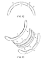
- the flexible adhesive 31 may be applied to the half-shell bearing in the form of an elongate bead of flexible adhesive as shown in Figure 8 and has a diameter or thickness of about 0.5mm. This means that when the thrust washers are brought to engagement with the half-shell bearing, although there will be some flattening and spreading out of the flexible adhesive bead, there is unlikely to be any movement or spreading of the flexible adhesive beyond the width of the thrust washers, which are typically between about 1 mm and about 2mm thick.
- the flexible adhesive 31 is applied to the back side or back surface of the half-shell bearing (i.e. opposite side of the bearing substrate to the running layer) which is not typically coated with the polymer-based running layer material, the flexible adhesive is applied to a bare metal surface.
- the face of the thrust washers that bears against the half-shell bearing i.e. the face connecting the inner and outer annular shaped side surfaces - the lower face as shown in the drawings
- the flexible adhesive will typically come into contact with a further bare metal surface. Therefore, when the thrust washers are brought to engagement with the half-shell bearing, the flexible adhesive will be sandwiched between two bare metal surfaces.
- one advantage of the use of a flexible adhesive is that it may be applied to a surface of any material and could therefore also be used on surfaces that are provided with a polymer-based running layer or a running layer comprising other materials.
- assembly of the flanged half-bearing involves positioning the half-shell bearing 21 with the beads of flexible adhesive 31 applied to the back side in an upturned position so as to form an arch and then simultaneously lowering the thrust washers 22,23 onto the half-shell bearing and continuing to lower them until the tabs 26,27 on the thrust washers engage with the recesses 24,25 in the half-shell bearing and the flexible adhesive is sandwiched between them to form the arrangement of Figures 5 to 7 .
- the thrust washers may be held relative to the half-shelf bearing (e.g. using a suitable jig) or the assembled flanged half-bearing may be left to rest (e.g. on a carrier) for the specified handling time until the flexible adhesive has cured sufficiently for the assembled flanged half-bearing to be self-supporting.
- the torque loads in the engine are primarily accommodated by the recesses and tabs which may have loose tolerances as they are not required to act as a clips for holding the flanged half-bearing together during handling and installation.
- the elongation at break (or elongation capacity) of the flexible adhesive is preferably sufficient for the flexible adhesive to remain adhered both to the thrust washers and to the half-shell bearing during a relatively small amount of rotation of the thrust washers relative to the half-shell bearing until the tabs come into contact with the sidewalls of the recesses and prevent further relative rotation of the thrust washers relative to the half-shell bearing.
- the aim is for the flexible adhesive to remain adhered to both the thrust washers and the half-shell bearing as the loose tolerances between the tabs and the recesses are taken up.
- the flexible adhesive will preferably also remain adhered both to the thrust washers and to the half-shell bearing throughout the operational life of the flanged half-bearing, although this is not essential as the flexible adhesive may be largely redundant once the flanged half-bearing has been installed in the engine.
- the flexible adhesive is used primarily to hold the assembled flanged half-bearing together during handling and installation and then, during operation of the flanged half-bearing, the tabs and notches become the primary connection between the thrust washers and the half-shell bearing.
- the flexible adhesive is applied to the half-shell bearing in a series of short runs or spots. This may advantageously require a smaller quantity of flexible adhesive and provide increased flexibility of the resulting flanged half-bearing compared to the application of a continuous bead of the first embodiment.
- Other suitable application regimes for the flexible adhesive will be readily apparent to the skilled person.
- the thrust washers 22,23 are each provided with a single notch 24,25 and the half-shell bearing 21 is provided with corresponding tabs 26,27 (i.e. the reverse of the earlier embodiments).
- the bead of flexible adhesive is applied to a side face of each thrust washer adjacent a lower curved edge of each washer. As shown in Figure 13 , the thrust washers are then brought into engagement with the side faces of the half-shell bearing, sandwiching the flexible adhesive bead between the thrust washers and the half-shell bearing.
- the flexible adhesive may be applied in any of the arrangements shown in Figures 10 to 13 . Other suitable application regimes for the flexible adhesive will also be readily apparent to the skilled person.
- one or both of the thrust washers may be provided with more than one tab for engagement with a corresponding number of recesses in the half-shell bearing (or vice versa).
- these are not required to act as a clips for holding the flanged half-bearing together, they will preferably extend in parallel to one another so that they simultaneously engage with the corresponding recesses during the assembly operation described above and with reference to Figure 9 , without any need for bending or pinching of the half-shell bearing.
- the flexible adhesive may be used in addition to one or more clips or tangs such as those used in some prior art flanged half-bearings.
- This may provide a flanged half-bearing having additional stiffness compared to a flanged half-bearing having only an adhesive coupling or only having the one or more clips or tangs.
- it may enable the clips or tangs have lower tolerances (i.e. a looser fit) than those that are used in some prior art flanged half-bearings which may have a number of benefits over the prior art flanged half-bearings having close tolerances, as described above.
- a suitable process for manufacturing a sliding element according to preferred embodiments of the present invention may comprise the following steps:-
- step a) and/or step b) of the method may involve several steps, including cutting or stamping first and/or second sliding element blanks from a sheet of raw materials, forming of the first or second sliding element blanks and applying one or more layers of material on the formed or unformed blank, for example an intermediate layer and/or a polymer-based running layer.
- step c it may be beneficial to wash and/or degrease the first sliding element component and/or the second sliding element component, or perhaps only the portions of those components that will come into contact with the flexible adhesive. Additional treatment of the surfaces, e.g. by grit blasting or shot peening is unlikely to be required and carries the risk of introducing impurities.
Abstract
Description
- This invention relates to a sliding element comprising a flexible adhesive.
- Sliding elements according to preferred embodiments of the present invention are particularly suitable for use as flanged (or flange) bearings, flanged half-bearings and flanged bushes for use in automotive applications, for example in automotive engines (e.g. on crankshafts), transmissions, pumps and compressor systems.
- In internal combustion engines, the bearing assemblies typically each comprise a pair of half-bearings retaining a crankshaft that is rotatable about an axis. For crankshaft journal bearing assemblies, at least one half-bearing may be a flanged half-bearing that comprises a hollow, generally semi-cylindrical, half-shell bearing provided with a generally semi-annular thrust washer extending outwardly (radially) at each axial end.
- OEMs in the automotive sector, including engine and subassembly manufacturers, typically specify that an assembled flanged bearing is supplied as part of the main bearing set. This allows for ease of installation and keeps the thrust washer in place during the life of the engine. The assembled flanged bearing is expected to be rigid enough to cope with transportation and handling by operators and/or robots and to be flexible enough to accommodate machining tolerances in the engine and to permit installation, e.g. into the designated space in an engine block. The flanged bearing is typically required to be provided with some means for supporting torque loads of the engine without the thrust washers becoming detached and rotating relative to the half-shell bearing.
- In some known flanged half-bearings, a single-piece construction of the half-shell bearing and thrust washers is used. In other known flanged half-bearings, the half-shell bearing and the thrust washer are loosely mechanically engaged with clip-like features. In a further type of flanged half-bearings the thrust washers are permanently assembled onto the half-shell bearing by deformation of corresponding engagement features.
- Known clip-like features for loosely mechanically engaging a thrust washer around the outer surface of a half-shell bearing, at an axial end, have a generally semi-annular panel with a pair of hooking lugs (tabs) projecting inwardly from the semi-circular inner edge. The hooking lugs hook into corresponding openings in the half-shell bearing, in use, when the thrust washer is connected around the outer surface at an axial end of the half-shell bearing. The inwardly projecting hooking lugs are located to either side of the crown of the bearing, towards the joint faces, and are shaped to enable the thrust washer to be assembled onto the half-shell bearing when the half-shell bearing is resiliently or elastically deformed by pinching together the joint faces (circumferential end faces). The arrangement by which the hooking lugs engage with the openings (recesses) prevents separation once the half-shell bearing has returned to the relaxed position, and also prevents separation when the half-shell bearing has been slightly pinched together through being held in an interference fit with a housing, within the full bearing assembly. The hooking lugs typically have a uniform thickness and are machined to be thinner than the main semi-annular panel of the thrust washer, to enable the use of (axially) narrow openings in the half-shell bearing. One or more stabilisation lugs may be provided intermediate the hooking lugs, projecting inwardly from the inner edge of the semi-annular main panel, to reinforce the connection between the thrust washer and half-shell bearing, to prevent wear leading to substantial relative rotation of the thrust washer and half-shell bearing.
- The prior art includes patent numbers
US4533261 , andEP2233759 which provide flanged half-bearings, in which thrust washers are loosely mechanically engaged with half-shell bearings using clip-like features comprising thin hooking lugs of uniform thickness receivable within openings in a corresponding half-shell bearing. - The prior art also includes PCT publication number
WO2013/068106 which provides a flanged half-bearing (330) comprising at least one substantially semi-annular thrust washer (100A, 100B) with an internal periphery having lateral lugs (104A, 104B) and an Intermediary stabilisation lug (106) projecting from the internal periphery (108) of the thrust washer, and a semi-cylindrical half journal half-shell bearing (220) having lateral recesses (226A, 226B) and an intermediary stabilisation recess (228) that are recessed into an axial end face (224A, 224B) of the half-shell bearing and are respectively connected to the lateral lugs and the stabilisation lug of the thrust washer, wherein the stabilisation lug (106) has rotational stabilisation edges (114) that project substantially perpendicularly from the inner periphery (108) of the thrust washer, and the stabilisation recess (228) is configured for axial relative movement of stabilisation lug; and an engine comprising at least one such flanged half-bearing (330). - The prior art also includes
PCT publication number WO2015/007826 which provides a thrust washer (100) for a flanged half-bearing, the thrust washer comprising: a substantially semi-annular panel (102) having an inner edge (108) and outer edge; and hooking lugs (110) projecting inwardly from the inner edge of the panel, wherein the hooking lugs have latching edges (118) that are configured to engage within corresponding openings in a half-shell bearing received by the thrust washer and to prevent disconnection of the thrust washer and half-shell bearing without deformation of the half-shell bearing, each hooking lug has a hooking lug inner portion (104A) proximate, around the inner edge of the panel, to the central part of the thrust washer for engaging against edges of the openings in the half-shell bearing and a hooking lug outer portion (104B) remote, around the inner edge of the panel, from the central part of the thrust washer, and the hooking lug inner portion is thinner than the hooking lug outer portion. - The inventors have appreciated that there may be a number of limitations or disadvantages associated with known types of flanged half-bearings such as those described in the aforementioned prior art references and illustrated in
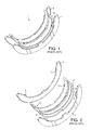
Figures 1 to 4 . These may comprise one or more of the following, among others:- - i. as shown in
Figures 1 to 4 , the prior art flanged half-bearings 1 use clips or 'tangs' 2,3,4,5 proximate the ends of thethrust washers recesses - ii. the clips or tangs of the prior art devices may require the ends of the half-shell bearing to be pinched to permit engagement of clips or 'tangs' with corresponding notches or recesses;
- iii. the clips or tangs of the prior art devices may lead to an increase in the manufacturing lead time;
- iv. the clips or tangs of the prior art devices may lead to scrappage of a higher proportion of assembled flanged half-bearings than may be desirable due the thrust washers not being correctly fitted to the half-shell bearing or becoming detached from the half-shell bearing during transportation and handling;
- v. the clips or tangs and the corresponding notches or recesses of the prior art being the only thing that forms a self-supporting flanged half-bearing necessitates the use of close tolerances between the clips or tangs and the corresponding notches or recesses. This may require the use of certain manufacturing processes and effective quality control;
- vi. the need for close tolerances may also necessitate the use of post-processing operations, such as deburring or the removal of ledges on the clips or tangs and/or the corresponding notches or recesses which may result from the initial forming operation, or the machining of one or more chamfers to facilitate engagement of the clips or tangs and the corresponding notches or recesses. This has the potential to introduce debris (e.g. swarf or metal particulate) which may have an adverse impact on the performance of the half-shell bearing and/or the thrust washers;
- vii. the need for additional post-processing operations may add to the cost of manufacture and may have an impact on the manufacturing lead time. It may also contribute to a higher proportion of the thrust washers and/or half-shell bearings being scrapped than may be desirable due to errors in the post-processing operations;
- viii. the clips or tangs of the prior art devices, may lead to the resulting flanged half-bearing having greater stiffness, or lower flexibility, than may be desirable for simple and effective installation of the flanged half-bearing into the end product, for example into a recess in an engine housing;
- ix. the use in some prior art devices of lines or runs of tack welding to join the thrust washers and the half half-shell bearing may necessitate the use of jigs to support each assembly during manufacture. The resulting flanged half-bearing may also be relatively stiff and have low flexibility which may be undesirable for simple and effective installation of the flanged half-bearing into the end product, for example an engine housing; and
- x. the use of welding also has the potential to introduce impurities and/or debris (e.g. weld dust) which may have an adverse impact on the performance of the half-shell bearing and/or the thrust washers.
- The inventors have appreciated that there is a need for an improved sliding element, particularly one to be used as a flanged half-bearing flanged bearing, that is more effective than known types of sliding elements, particularly known types of flanged half-bearings, for use in automotive engine applications, including in engines operating stop-start schemes and in particular where the sliding element is to be used to support rotating components such as the crankshaft.
- In the following description, the term "flexible" preferably means that once cured, the adhesive remains flexible and provides a flexible coupling between the first and second sliding element components. The term "flexible" preferably means that the adhesive is able to elongate in use of the sliding element.
- In the following description, the term "elongation at break" preferably means the elongation at break measured in accordance with ISO 527-3:1995 (Plastics -- Determination of tensile properties -- Part 3: Test conditions for films and sheets) or in accordance with ISO 37:2005 (Rubber, vulcanized or thermoplastic -- Determination of tensile stress-strain properties) or in accordance with the corresponding ISO standard test for the relevant flexible adhesive material.
- In the following description, the term "handling time" preferably means the period of time that it takes for the flexible adhesive, once dispensed from suitable dispensing apparatus onto a first and/or a second sliding element component, to cure sufficiently so that the flexible adhesive is able to hold the first and second sliding element components together and form a self-supporting sliding element assembly. After this handling time has expired, the sliding elements may be handled (e.g. to be inspected for quality control purposes or to be packaged for transportation), but it may take further time (e.g. up to 7 days) for the flexible adhesive to be fully cured.
- The present invention is defined in the appended independent claims and provides, in a first aspect, a sliding element, comprising: a first sliding element component for sliding engagement with a rotatable component; and a second sliding element component for sliding engagement with a rotatable component; wherein a portion of the first sliding element component is coupled to a portion of the second sliding element component by an adhesive; and wherein the adhesive is a flexible adhesive.
- In preferred embodiments of the present invention, the sliding element may take the form of a flanged half-bearing which comprising a half-shell bearing and a pair of thrust washers coupled to the half-shell bearing to form a self-supporting assembly.
- Preferred embodiments of the present invention are particularly suitable for use in one or more of the following: automotive engines; transmissions; pumps; and compressor systems.
- The inventors believe that the improved sliding element of the present invention may have a number of advantages over the prior art devices, which may comprise some or all of the following, among others:-
- i. the use of a flexible adhesive instead of the clips or tangs of some prior art devices to couple the half-shell bearing and the thrust washers to form a self-supporting flanged half-bearing may reduce the complexity of the sliding element compared to prior art devices and make it quicker and easier to assemble the flanged half-bearing;
- ii. the use of a flexible adhesive instead of the clips or tangs of some prior art devices may make it quicker and easier to form a self-supporting flanged half-bearing by eliminating the need for manual handling of the thrust washers and the half-shell bearing;
- iii. the use of a flexible adhesive instead of the clips or tangs of some prior art devices may reduce or eliminate the need for pinching of the half-shell bearing in order to engage the thrust washers;
- iv. the use of a flexible adhesive instead of the clips or tangs of some prior art devices may reduce the manufacturing lead time due to the removal of fiddly manual operations;
- v. the use of a flexible adhesive instead of the clips or tangs of some prior art devices may reduce or eliminate the volume of scrap of reject prior art flanged half-bearings which have been incorrectly assembled or which have become detached during transportation and handling;
- vi. the use of a flexible adhesive instead of the clips or tangs of some prior art devices may reduce or eliminate the need for close tolerances between the clips or tangs and the corresponding notches or recesses which should simply the manufacturing process and reduce the associated cost;
- vii. the use of a flexible adhesive instead of the clips or tangs of some prior art devices may reduce or eliminate the need for port-processing operations, including deburring or the removal of ledges on the clips or tangs and/or the corresponding notches or recesses which may result from the initial forming operation. This may further simplify the manufacturing process and reduce the associated cost. It may also reduce or eliminate the introduction of debris (e.g. swarf or metal particulate) which may otherwise have an adverse impact on the performance of the half-shell bearing and/or the thrust washers;
- viii. the use of a flexible adhesive instead of the clips or tangs or welding of some prior art devices may reduce the stiffness and increase the flexibility of the resulting flanged half-bearings. This may facilitate installation of the flanged half-bearings into the end product, for example an engine housing. It may also reduce the proportion of scrap compared to prior devices that may be too stiff and insufficiently flexible to be installed into the engine housing;
- ix. the use of a flexible adhesive instead of the welding used in some prior art devices may reduce or eliminate the associated debris (e.g. weld dust) which may otherwise have an adverse impact on the performance of the half-shell bearing and/or the thrust washers; and
- x. preferably, there will not be any degradation or dissolving of the flexible adhesive during use of the flanged bearing. However, the use of a flexible adhesive instead of the welding used in some prior art devices may mean that if there were any minor degradation or dissolving of the flexible adhesive, the resulting debris may be softer than the metal debris that is commonly associated with the prior art devices incorporating welding and may therefore be more likely to pass through the bearing clearance without damaging to the running surfaces of the thrust washers and/or the half-shell bearing or affecting the performance of the flanged half-bearing;
- xi. the flexible adhesive may be used to adhere sliding element components made from, or coated with any chosen materials. For example, the flexible adhesive may be used to adhere sliding element components comprising a polymer-based running layer and irrespective of whether it contains any additives or particulate materials such as metal particulates.
- In arriving at the present invention, the inventors have reduced the complexity of the prior art devices by, and taken the counterintuitive step of, removing the need for precision-machined clips and tangs with close tolerance, and the need for welding, and replacing them with a simple flexible adhesive connection. In order to arrive at this simple and effective solution, the inventors have taken a step back from the known path of development of flanged half-bearings and made an improvement which has a number of clear advantages compared to the use of known flanged half-bearings. The inventors have effectively reengineered the construction of flanged half-bearings and provided an elegant solution to the limitations associated with known flanged half-bearings by making them simpler and cheaper to make and simpler and easier to use.
- The inventors have appreciated that selection of the flexible adhesive is key to the performance of the resulting sliding element. Preferably, the flexible adhesive will have some or all of the following properties, among others:-
- i. a suitable balance between cure time and flexibility of the sliding element. In order for the flexible adhesive to cure quickly, the sliding element may end up being stiffer and less flexible than may be desirable. However, in order for the sliding element to be reasonable flexible, the cure time of the flexible adhesive may be longer than may be desirable which may affect the manufacturing lead time;
- ii. a viscous flexible adhesive that is self-supporting as soon as it is dispensed, or soon after it is dispensed, from the dispensing apparatus, and that remains self-supporting as it cures. There may be a balance to be achieved here between ensuring that the flexible adhesive may be dispensed relatively quickly and uniformly and ensuring that the flexible adhesive is viscous and self-supporting and resistant to running or smearing;
- iii. the adhesive, once cured, has a relatively high elongation at break (or elongation capacity). If its elongation capacity is too low, the flexible adhesive may have a tendency to reach its elastic limit too early and fail during handling or installation of the sliding element. However, in order for its elongation capacity to be high, that may require the flexible adhesive to be quite fluid which may necessitate a longer cure time before it is self-supporting which may have an impact on the manufacturing lead time;
- iv. offer good resistance to degradation in the presence of lubricants such as engine oil;
- v. offer good resistance to degradation in the operating temperatures associated with automotive engines; and
- vi. have sufficient bond strength or adhesion strength to offer some torque load capability. However, as discussed below in relation to preferred embodiments of the present invention, the bond strength need not be particularly high due to the preference for the sliding element to comprise at least one additional mechanical connection between the first and second sliding element components. There is also a balance to be achieved between the flexible adhesive having sufficient bond strength or adhesion strength offering some torque load capability and ensuring that the sliding element retains some flexibility.
- Some preferred features of the present invention are set out in the dependent claims to which reference should now be made.
- Preferably, the sliding element is for supporting a rotatable shaft. Preferably, the sliding element is for supporting a crankshaft and/or a camshaft. Preferably, the sliding element is for supporting a crankshaft for an automotive engine.
- Preferably, the first sliding element component comprises a bearing element (e.g. a half-shell bearing). The half-shell bearing may be a simple known type of half-shell bearing, such as a metal or bi-metal half-shell bearing that is typically used in the construction of flanged half-bearings for automotive engine applications. Alternatively, the bearing may, for example, comprise a polymer-based running layer or a sintered coating of a suitable material.
- Preferably, the second sliding element component comprises at least one thrust washer. More preferably, the second sliding element component comprises a pair of thrust washers. The thrust washers may be identical or different from one another. The thrust washers may be a simple, known-type of thrust washer, such as a metal or bi-metal thrust washer that is typically used in the construction of flanged half-bearings for automotive engine applications. Alternatively, the bearing may, for example, comprise a polymer-based running layer or a sintered coating of a suitable material.
- Particularly suitable thrust washers comprise, for example, improved thrust washers of the type described in published international patent application number
WO2014/091206 , providing a thrust washer comprising a polymer layer of profiled thickness, or of the type described in UK patent application number United Kingdom Patent Application No.1507205.1 - Preferably, the thrust washers are adhered to the bearing element by the flexible adhesive. As will be discussed below, the flexible adhesive may be applied to the half-shell bearing. Alternatively, the flexible adhesive may be applied to each thrust washer. Alternatively, the flexible adhesive may be applied both to the half-shell bearing and to each thrust washer. As will be discussed below, when the flexible adhesive is applied to the half-shell bearing, it may be applied to the back side of the half-shell bearing. Alternatively, it may be applied to the side face of the half-shell bearing. When the flexible adhesive is applied to the thrust washers, it may be applied to a top or bottom face of each thrust washer. Alternatively, it may be applied to the side face of each thrust washer.
- Preferably, the flexible adhesive, once cured, has an elongation at break (or elongation capacity) of between about 100 percent and about 500 percent. Preferably, the flexible adhesive, once cured, has an elongation at break (or elongation capacity) of between about 350 percent and about 450 percent, preferably about 400 percent. This may reduce the likelihood of the flexible adhesive being detached from the first and/or the second sliding element component during handling or installation of the sliding element or during use of the sliding element.
- The flexible adhesive may comprise a flexible silicone or a flexible oxime silicone or a flexible alkoxy silicone. Alternatively, the flexible adhesive may comprise a flexible rubber, a flexible nitrile or a flexible epoxy or a flexible polyurethane or a flexible epoxy polysulphide or a hybrid comprising any two or more of these materials.
- Preferably, the adhesive comprises a powertrain grade flexible adhesive comprising a silicone or an oxime silicone or an alkoxy silicone.
- Preferably, the flexible adhesive comprises an oxime silicone. This is a non-acidic type of silicone which should not corrode a metal or bi-metal substrate to which the flexible adhesive may be applied. Oxime silicones also offer good resistance to degradation or decomposition in the presence of lubricants, including automotive engine oils. However, other types of silicones may be also used including, for example, an alkoxy silicone which is also a non-acidic (or neutral) type of silicone and is reasonably fast curing and exhibits reasonably high strength. In some circumstances it may be desirable to use an acetoxy silicone due to its fast curing time and high strength but as this is an acidic type of silicone, it may carry a risk of corrosion of a metal or bi-metal substrate.
- Preferably, the flexible adhesive is resistant, during use of the sliding element, to lubricants, particularly engine oils, and to typical engine operating temperatures, particularly in the region of about 90 degrees C to about 150 degrees C. This makes the flexible adhesive particularly suitable for use in engines, for example, where the sliding element is used to support a crankshaft and is immersed in engine lubricating oil.
- Preferably, the flexible adhesive is a single part flexible adhesive. The flexible adhesive may alternatively be a multi-part flexible adhesive (e.g. a two-part or a three-part flexible adhesive). A single part flexible adhesive may be quicker and easier to apply and may be stored in the applicator head of a dispensing apparatus for a longer period of time before it cures (sometime referred to as "pot life"), and the applicator head must be replaced or cleaned. A multi-part flexible adhesive (e.g. a two-part flexible adhesive) may provide a faster curing time and thereby a reduction in the manufacturing lead time. However, it may also have a shorter pot life.
- Preferably, the flexible adhesive is a viscous, substantially self-supporting, flexible adhesive. This may reduce a likelihood of the flexible adhesive running or smearing and contaminating other areas of the first and/or second sliding element component. It may also reduce the need for delicate handling of the first and/or second sliding element components to which the flexible adhesive has been applied. It may also reduce the period of time they must remain stationary once the flexible adhesive has been applied before they may be handled (i.e. reduce the handling time).
- Preferably, the flexible adhesive is a room temperature curing flexible adhesive (e.g. a Room Temperature Vulcanising (RTV) silicone). Alternatively, the flexible adhesive may be cured by another means, for example by an ultraviolet (UV) curing process, though this would necessitate the use of dedicated UV curing equipment and would require line of sight through any joints in order to ensure that the flexible adhesive is fully cured.
- Preferably, the flexible adhesive has a bond strength or adhesion strength of between about 0.5MPa and about 5MPa. More preferably, the flexible adhesive has a bond strength or adhesion strength of between about 1 MPa and about 2MPa. More preferably, the flexible adhesive has a bond strength or adhesion strength of between about 1.5MPa and about 2MPa. Such a bond strength or adhesion strength is expected to provide a suitable balance between ensuring that the flexible adhesive has some torque load capability and is sufficiently flexible to facilitate handling and installation of the resulting sliding element.
- The flexible adhesive may be applied to the first sliding element component (which may, according to preferred embodiments of the invention, be a half-shell bearing) or to the second sliding element component (which may, according to preferred embodiments of the invention, be one or more thrust washers) or to both the first sliding element component and the second sliding element component. It may be easier to apply to the flexible adhesive to the first sliding element component (e.g. a half-shell bearing) due to the greater width of the half-shell bearing compared to the width of the thrust washers.
- The flexible adhesive may be applied in the form of an elongate bead of flexible adhesive. This may be the simplest and most uniform method of application of the flexible adhesive. However, it may require a larger quantity of flexible adhesive and may increase the manufacturing lead time compared to alternative flexible adhesive application regimes. It may also increase the stiffness and reduce the flexibility of the resulting sliding element compared to alternative flexible adhesive application regimes.
- Alternatively, the flexible adhesive may be applied in a series of short runs or spots. This may require a smaller quantity of flexible adhesive and/or may reduce the manufacturing lead time compared to the application of a continuous bead. It may also reduce the stiffness and increase the flexibility of the resulting sliding element compared to the application of a continuous bead. As discussed elsewhere in this specification, greater flexibility may be desirable during handling and installation of the sliding element.
- Using high quality dispensing equipment should mean that regardless of the chosen application regime, the flexible adhesive may be metered out very accurately and so that the diameter of the bead or short runs or spots is substantially uniform and there is there is minimal spreading of the flexible adhesive when the first sliding element component (e.g. a half-shell bearing) and the second sliding element component (e.g. thrust washers) are brought into engagement to form the sliding element.
- The flexible adhesive (whether applied as a continuous bead or a series of short runs or spots) may be applied only to the part of the first sliding element component (e.g. a half-shell bearing) that is expected to come into contact with the second sliding element component). The flexible adhesive may be applied to the first sliding element component and/or the second sliding element component as required to provide the desired properties of the sliding element (e.g. the stiffness or flexibility of the sliding element).
- As thrust washers for flanged half-bearings for automotive applications are typically between about 1 mm and about 5mm thick, the bead of flexible adhesive is preferably applied to the first sliding element component (e.g. a half-shell bearing) so that it has a diameter or thickness of less than the thickness of the thrust washer. For example, where the thrust washers are, say, 1 mm thick, the adhesive is preferably applied so that it has a thickness or diameter of between about 0.1mm and about 1mm, more preferably between 0.4mm and about 0.6mm, more preferably about 0.5mm.
- Preferably, the first sliding element component is additionally coupled to the second sliding element component by one or more mechanical couplings. This may enable the sliding element to withstand higher torque loads that might otherwise overcome the bond strength or adhesion strength of the flexible adhesive or lead to the flexible adhesive extending beyond the limit of its elasticity and cause the flexible adhesive to fail. For example, in a flanged half-bearing according to preferred embodiments of the present invention, the one or more mechanical couplings may prevent the thrust washers from rotating, during use of the flanged half-bearing, relative to the half-shell bearing.
- Preferably, the one or more mechanical couplings comprises one or more notches, recesses, cut-outs or slots on the first sliding element component (e.g. a half-shell bearing) for engagement with corresponding tabs or tags on the second sliding element component (e.g. the thrust washers).
- Preferably, the first sliding element component (e.g. a half-shell bearing), comprises a single recess or cut-out in each side of the half-shell bearing that is positioned at, or near to, the crown of the half-shell bearing. Preferably, the second sliding element component (e.g. the thrust washers), comprises a single tab extending at or near the crown of each thrust washer in a direction that is perpendicular to a tangent to the curved outer surface of the thrust washer. In other words, the single tab preferably extends towards a centre of curvature of the thrust washer. Preferably, the tabs are engageable with the recesses so as to interlock the first and second sliding element components and constrain them relative to one another so as to prevent relative rotation of the first and second sliding element components.
- Alternatively, the first sliding element component (e.g. a half-shell bearing) may comprise a single tab and the second sliding element component (e.g. the thrust washers), may comprise a single recess or cut-out (i.e. the reverse of the arrangement described above).
- In a further alternative embodiment (not shown in the Figures), the flexible adhesive may be used in addition to one or more clips or tangs such as those used in some prior art flanged half-bearings. This may provide a flanged half-bearing having additional stiffness compared to a flanged half-bearing having only an adhesive coupling or only having the one or more clips or tangs. Alternatively, it may enable the clips or tangs have lower tolerances (i.e. to be a looser fit) than those that are used in some prior art flanged half-bearings, which may have a number of benefits over the prior art flanged half-bearings having close tolerances, including some or all of the benefits described above.
- An advantage of the use of a recess at or near the crown of the first sliding element component (e.g. the half-shell bearing) and a tab extending at or near the crown of the second sliding element component (e.g. the thrust washers) is that these mechanical features may be formed during the initial forming operation (e.g. by stamping, laser cutting or another suitable process) when the first and second sliding element components are formed as blanks from sheet material. The interlocking or interleaved nature of the arrangement of the components, particularly the thrust washers, on a sheet of raw material is such that the tabs are formed from raw material that would otherwise be discarded as scrap.
- The recesses of the first sliding element component (e.g. the half-shell bearing) and the tabs of the second sliding element component (e.g. the thrust washers) may be spaced from the crown of first sliding element component and the second sliding element component so as to provide a mistake-proofing (or 'poka-yoke') device to assist operators on the manufacturing line to identify the correct orientation of the thrust washers relative to the half-shell bearing.
- Preferably, one or both of the half-shell bearing and the thrust washers comprises a polymer-based running layer. Other running layer materials may also be used, including a sintered coating of a suitable material. A further advantage of sliding elements according to preferred embodiments of the present invention comprising a flexible adhesive is that, unlike in some known machined flanged bearings, different materials can be used for the bearing and thrust washer running surfaces or running layers. For example, one of them may have a polymer-based running layer and the other may have a running layer or surface made from a different material.
- Preferably, the polymer-based running layer is formed on the half-shell bearing and/or the thrust washer substrate by a spraying or a screen printing process.
- The polymer-based running layer be applied directly to the thrust washer substrate and/or the half-shell bearing substrate. Alternatively, the polymer-based running layer may be applied to an intermediate layer applied to the thrust washer substrate and/or the half-shell bearing substrate. The thrust washer substrate and/or the half-shell bearing substrate may be a metal or bi-metal substrate. The intermediate layer may also be a metal or bi-metal layer.
- The polymer-based running layer may be formed by depositing a plurality of polymer-based sub-layers. The plurality of polymer-based sub-layers may comprise sub-layers of the same or different thicknesses. Successive polymer running layers may be differently patterned, to build up a profiled polymer-based running layer of non-uniform thickness. The use of sub-layers may provide greater control of the thickness of the profiled polymer running layer.
- The present invention is further defined in the appended independent claims and provides, in a second aspect a flanged half-bearing comprising the sliding element of the first aspect of the invention.
- The present invention is further defined in the appended independent claims and provides, in a third aspect a flanged bush comprising the sliding element of the first aspect of the invention.
- The present invention is further defined in the appended independent claims and provides, in a fourth aspect, an engine comprising the sliding element of the first aspect of the invention or the flanged half-shell bearing of the second aspect of the invention or the flanged bush of the third aspect of the invention.
- The present invention is further defined in the appended independent claims and provides, in a fifth aspect, a method of manufacturing a sliding element or a flanged half-bearing or a flanged bush of the first, second and third aspects of the invention. The method comprises the steps of:-
- providing a first sliding element component for supporting rotatable engine component; and
- providing a second sliding element component for supporting a rotatable engine component;
- applying a flexible adhesive comprising silicone to a portion of the first sliding element component and/or to a portion of the second sliding element component;
- bringing the first sliding element and the second sliding element component into engagement to form an assembly;
- allowing the adhesive to at least partially cure for a handling time so as to form a self-supporting sliding element or a flanged half-bearing or a flanged bush assembly.
- Preferably, the handling time is between about 5 minutes and about 20 minutes in an ambient environment. This may provide a suitable balance between the required manufacturing lead time and the ability to handling the self-supporting sliding element or flanged half-bearing or flanged bush assembly after the handling time.
- The axial face of the thrust washer may be provided with one or more oil distribution grooves running between the inner and outer edges of the thrust washer. Preferably, the oil distribution grooves extend across the thrust washer from the inner edge to the outer edge in a continuous arrangement enabling through flow of oil. The axial face of the polymer-based running layer may therefore comprise a plurality of disconnected portions, separated by the one or more oil distribution grooves. The provision of the oil distribution grooves in the axial face of the thrust washer may enhance the quality of the oil film between the thrust washer and the shaft. In use, lubricating oil may be pumped into the bearing clearance between the corresponding half-shell bearing and rotating crankshaft journal, and leaks out into the further clearance between the thrust washer and the counterface of the rotating crankshaft web.
- The oil grooves may extend all the way through a depth of the polymer running layer. In this arrangement, a base of the grooves may be formed by the thrust washer substrate or by an intermediate layer positioned on the thrust washer substrate. This may result, for example, from applying the polymer-based running layer to the thrust washer substrate by a spraying or screen printing process in which the polymer-based running layer is applied to the substrate (or an intermediate layer) in a single spraying or screen printing operation, or in a series of spraying or screen printing operations, using a mask to prevent application of the polymer-based running layer on certain portions of the thrust washer substrate.
- Alternatively, the oil grooves may extend partially through a depth of the polymer-based running layer deposited on the thrust washer substrate. In this arrangement, the base of the grooves may be formed by a portion of the thickness of the polymer-based running layer. This may result, for example, from applying the polymer-based running layer over the entire axial face of the thrust washer substrate and subsequently removing a portion of the axial face of the polymer-based running layer using a material removal process, or by applying the polymer to the thrust washer substrate in a series of sublayers i.e. building up the polymer-based running layer using a series of two or three or more layers and subsequently removing a portion of only one, or some, of the sublayers to form the oil grooves.
- The thrust washers and/or the half-shell bearing may be provided with joint face relief portions at one or both ends.
- Although the various Figures and the associated description show flanged half-bearings (i.e. flanged semi-annular bearings, the present invention equally applies to flanged bearings (i.e. flanged annular bearings).
- Some example embodiments of the present invention will now be described with reference to the accompanying drawings, in which:-
-
Figure 1 is a perspective view of a prior art sliding element in the form of a flanged half-bearing comprising a half-shell bearing and a pair of thrust washers; -
Figure 2 is an exploded perspective view of the prior art flanged half-bearing ofFigure 1 ; -
Figure 3 is a perspective view of a further prior art sliding element in the form of a flanged half-bearing comprising a half-shell bearing and a pair of thrust washers; -
Figure 4 is an exploded perspective view of the prior art flanged half-bearing ofFigure 3 ; -
Figure 5 is a perspective view of a sliding element according to a first example embodiment of the present invention in the form of a flanged half-bearing comprising a half-shell bearing and a pair of thrust washers; -
Figure 6 is a further perspective view of the flanged half-bearing ofFigure 5 ; -
Figure 7 is a side view of the flanged half-bearing ofFigure 5 ; -
Figure 8 is a perspective view of the half-shell bearing of the flanged half-bearing ofFigure 5 ; -
Figure 9A is a further side view of the flanged half-bearing ofFigure 5 with the thrust washers in an elevated position above the half-shell bearing ofFigure 8 ; -
Figure 9B is a further side view of the flanged half-bearing ofFigure 5 with the thrust washers brought into engagement with the half-shell bearing ofFigure 8 ; -
Figure 10 is a perspective view of a half-shell bearing of a sliding element according to a second example embodiment of the present invention; -
Figure 11 is a perspective view of a half-shell bearing of a sliding element according to a third example embodiment of the present invention; -
Figure 12 is a side view of a thrust washer of a sliding element according to a fourth example embodiment of the present invention; and -
Figure 13 is a perspective view of a flanged half-bearing comprising the thrust washer ofFigure 12 in which the thrust washer is being brought into engagement with a corresponding half-shell bearing. -
Figures 5 to 9 illustrate a slidingelement 20 according a first example embodiment of the present invention in which the sliding element takes the form of a flanged half-bearing comprising a half-shell bearing 21 and a pair ofthrust washers - The semi-annular half-
shell bearing 21 comprises anotch 24,25 (or recess or cut-out or slot) on each side of the back side of the bearing at or near the crown. Eachsemi-annular thrust washer - The notches of the half-shell bearing are configured to receive the tabs of the thrust washers so that when the tabs of the thrust washers are received within the notches, a face of the thrust washer that connects the annular side surfaces (i.e. a lower surface as shown in the Figures) abuts a back side of the half-shell bearing (i.e. the opposite side to the side of the half-shell bearing which provides a running surface for a shaft supported by the flanged half-bearing - the upper surface as shown in the Figures).
- As will be discussed further below, one important advantage of the use of a flexible adhesive to couple the half-shell bearing and the thrust washers instead of the clips or tangs of some prior art flanged half-bearings, is that the tabs and the notches do not need to be precision machined and only need have loose tolerances. In other words, the tabs need only have a relatively loose fit within the notches compared to those of some known flanged half-bearings comprising clips or tangs.
- When the thrust washers and the half-shell bearing are assembled as shown in
Figure 9 to form the flanged half-bearing 20 ofFigure 5 , thethrust washers shell bearing 21. In other words, the thrust washers are hung from opposite sides of the half-shell bearing. - The tabs may be spaced a short distance from the crown of the thrust washers and in the same direction on the opposing thrust washers to ensure that they may only be fitted in the correct orientation (i.e. to provide a poka yoke).
- Each half-shell bearing may comprise a joint face relief portion at each end for accommodate cap shift of two opposing half-shell bearings.
- Each thrust washer may comprises one or more
oil distribution grooves chamfer 30 along an edge. - Each thrust washers comprises a thrust washer substrate, which may be a bimetal thrust washer substrate and a sliding layer, commonly referred to as a 'running layer', 'sliding layer' or 'overlay', applied to the thrust washer substrate. The running layer of each thrust washer is preferably a polymer-based running layer.
- The half-shell bearing comprises a bearing substrate, which may be a bimetal substrate and a sliding layer applied to the bearing substrate. The running layer is preferably a polymer-based running layer.
- The polymer-based running layer of the thrust washers and/or the half-shell bearing is formed of a running layer material and is formed on the underlying thrust washer substrate to give the thrust washer the desired characteristics e.g. the desired load carrying capacity and wear resistance. The matrix of the running layer material (which generally provides the highest volume percentage portion of the running layer material) is formed of a polymeric material. Examples of suitable polymeric materials comprise: cross-linkable bonding agents; thermosetting plastics; high melting point thermoplastics; materials comprising a matrix of at least one high melting point thermoplastic material; fibre-reinforced plastics; any combination of these materials. Other suitable materials are envisaged and will be readily apparent to the skilled person. Particularly suitable polymeric materials comprise: PAI (Polyamide-imide); PI (Polyimide); epoxy; epoxy resin; phenolic resin; silicone resin; polyether ether ketone or a combination of any of these materials. These materials are characterised by high temperature resistance and excellent media resistance (such as chemical resistance to lubricants). One particularly preferred polymeric material for thrust washers according to preferred embodiments of the present invention is Polyamideimide (PAI).
- The running layer material may comprise a composite of a plastics polymer matrix with one or more particulates. For example, running layer material may comprise a hard particulate to provide improved wear resistance (e.g. ceramic powder, silica, and metal powder such as aluminium flakes). Other suitable materials are envisaged and will be readily apparent to the skilled person.
- The running layer material may optionally comprise at least one soft particulate e.g. a solid lubricant. Suitable solid lubricants comprise: metal sulphides with layered structures; graphite; hexagonal boron nitride (h-BN); molybdenum disulfide (MoS2); tungsten disulphide (WS2); a fluoropolymer such as PTFE; or a combination of any of these materials. Other suitable materials are envisaged and will be readily apparent to the skilled person.
- The running layer material may comprise a matrix of a Polyamide-imide plastics polymer material and comprising distributed throughout the matrix: between about 5%vol and about 15%vol of a metal powder; between about 1%vol and about 15%vol of a fluoropolymer, the balance being the Polyamide-imide resin (apart from incidental impurities).
- The running layer material may optionally comprise one or more additional materials or particulates in order to tailor its properties to a particular application, as will be readily apparent to the skilled person.
- Optionally, each thrust washer substrate and/or the bearing substrate may comprise an intermediate layer which may provide an improved surface for adhesion of the polymer-based running layer and may be advantageous when certain supporting materials are used. Suitable materials for the optional intermediate layer comprise nickel, silver, copper and/or iron or alloys comprising one or more of such materials. The optional intermediate layer may comprise a combination of two or more or such materials/alloys. The intermediate layer may also comprise an adhesion promoter and/or be subjected to a pre-treatment, for example a phosphating, chromating or silicating treatment. Other suitable materials are envisaged and will be readily apparent to the skilled person.
- In addition to the
tabs flexible adhesive 31 is used to adhere each thrust washer to the back side of the half-shell bearing so as to provide a self-supporting flanged half-bearing assembly. - The flexible adhesive is resistant, during use of the flanged half-bearing, to engine oil and to engine temperatures in the region of about 90 degrees C to about 150 degrees C. This makes it particularly suitable for use in automotive engine environments, for example, where the flanged half-bearing is used to support a crankshaft and where it is immersed in engine lubricating oil or regularly comes into contact with engine oil.
- Suitable flexible adhesives comprise powertrain grade flexible adhesives comprising silicone. A particularly suitable flexible adhesive comprises an oxime silicone. Such types of silicone are non-acidic and exhibits good resistance to automotive engine oils and operating temperatures. Other suitable flexible adhesive materials have already been described above.
- The flexible adhesive is a single part flexible adhesive and is highly viscous and self-supporting. Preferably the flexible adhesive is a thixotropic material, preferably a thixotropic paste. The flexible adhesive is preferably, is cured at room temperature.
- The flexible adhesive preferably has, once cured:-
- (i) an elongation at break, according to ISO 37, of greater than about 100 percent or about 150 percent or about 200 percent or about 250 percent or about 300 percent or about 350 percent or about 400 percent and/or less than about 400 percent or about 350 percent or about 300 percent or about 250 percent or about 200 percent or about 150 percent; or
- (ii) an elongation at break, according to ISO 527-3 of greater than about 50 percent or about 100 percent or about 150 percent or about 200 percent or about 250 percent and/or less than about 250 percent or about 200 percent or about 150 percent or about 100 percent.
- In one suitable type of flexible adhesive comprising an oxime silicone, the adhesive preferably has, once cured for 7 days at 25 degrees C and 50±5 percent Relative Humidity (RH) an elongation at break according to ISO 37 of greater than or equal to about 400 percent.
- In another suitable type of flexible adhesive comprising an alkoxy silicone, the adhesive preferably has, once cured for 7 days at 22 degrees C and 50 percent Relative Humidity (RH) an elongation at break according to ISO 527-3 of about 210 percent.
- It may be possible to accelerate the curing process of the adhesive, if required, by increasing the temperature and/or the humidity.
- As a result of the desired characteristics of the flexible adhesive, including requirement for flexibility, the flexible adhesive is likely to have an adhesion strength of between about 0.5MPa to about 5MPa.
- The flexible adhesive has a handling time of between about 5 minutes and about 30 minutes. Preferably, it has a handling time of between about 5 minutes and about 10 minutes. After expiry of the handling time, the flexible adhesive provides a self-supporting flanged half-bearing assembly which may then continue along the manufacturing line and, for example be subject to quality control checks and packaged for transportation. It is likely to take longer than the handling time for the flexible adhesive to be fully cured.
- The
flexible adhesive 31 may be applied to the half-shell bearing in the form of an elongate bead of flexible adhesive as shown inFigure 8 and has a diameter or thickness of about 0.5mm. This means that when the thrust washers are brought to engagement with the half-shell bearing, although there will be some flattening and spreading out of the flexible adhesive bead, there is unlikely to be any movement or spreading of the flexible adhesive beyond the width of the thrust washers, which are typically between about 1 mm and about 2mm thick. - As the
flexible adhesive 31 is applied to the back side or back surface of the half-shell bearing (i.e. opposite side of the bearing substrate to the running layer) which is not typically coated with the polymer-based running layer material, the flexible adhesive is applied to a bare metal surface. As the face of the thrust washers that bears against the half-shell bearing (i.e. the face connecting the inner and outer annular shaped side surfaces - the lower face as shown in the drawings) is not typically coated with the polymer-based running layer material, the flexible adhesive will typically come into contact with a further bare metal surface. Therefore, when the thrust washers are brought to engagement with the half-shell bearing, the flexible adhesive will be sandwiched between two bare metal surfaces. However, one advantage of the use of a flexible adhesive is that it may be applied to a surface of any material and could therefore also be used on surfaces that are provided with a polymer-based running layer or a running layer comprising other materials. - As shown in
Figure 9 , assembly of the flanged half-bearing involves positioning the half-shell bearing 21 with the beads of flexible adhesive 31 applied to the back side in an upturned position so as to form an arch and then simultaneously lowering thethrust washers tabs recesses Figures 5 to 7 . Following the initial assembly, the thrust washers may be held relative to the half-shelf bearing (e.g. using a suitable jig) or the assembled flanged half-bearing may be left to rest (e.g. on a carrier) for the specified handling time until the flexible adhesive has cured sufficiently for the assembled flanged half-bearing to be self-supporting. - In use of the flanged half-bearing, the torque loads in the engine are primarily accommodated by the recesses and tabs which may have loose tolerances as they are not required to act as a clips for holding the flanged half-bearing together during handling and installation.
- The elongation at break (or elongation capacity) of the flexible adhesive is preferably sufficient for the flexible adhesive to remain adhered both to the thrust washers and to the half-shell bearing during a relatively small amount of rotation of the thrust washers relative to the half-shell bearing until the tabs come into contact with the sidewalls of the recesses and prevent further relative rotation of the thrust washers relative to the half-shell bearing. In other words, the aim is for the flexible adhesive to remain adhered to both the thrust washers and the half-shell bearing as the loose tolerances between the tabs and the recesses are taken up.
- The flexible adhesive will preferably also remain adhered both to the thrust washers and to the half-shell bearing throughout the operational life of the flanged half-bearing, although this is not essential as the flexible adhesive may be largely redundant once the flanged half-bearing has been installed in the engine. The flexible adhesive is used primarily to hold the assembled flanged half-bearing together during handling and installation and then, during operation of the flanged half-bearing, the tabs and notches become the primary connection between the thrust washers and the half-shell bearing.
- In the second and third embodiments illustrated in
Figures 10 and 11 , the flexible adhesive is applied to the half-shell bearing in a series of short runs or spots. This may advantageously require a smaller quantity of flexible adhesive and provide increased flexibility of the resulting flanged half-bearing compared to the application of a continuous bead of the first embodiment. Other suitable application regimes for the flexible adhesive will be readily apparent to the skilled person. - In the fourth embodiment illustrated in
Figures 12 and 13 , thethrust washers single notch shell bearing 21 is provided withcorresponding tabs 26,27 (i.e. the reverse of the earlier embodiments). The bead of flexible adhesive is applied to a side face of each thrust washer adjacent a lower curved edge of each washer. As shown inFigure 13 , the thrust washers are then brought into engagement with the side faces of the half-shell bearing, sandwiching the flexible adhesive bead between the thrust washers and the half-shell bearing. It will be appreciated that the flexible adhesive may be applied in any of the arrangements shown inFigures 10 to 13 . Other suitable application regimes for the flexible adhesive will also be readily apparent to the skilled person. - In a further alternative embodiment (not shown in the Figures), one or both of the thrust washers may be provided with more than one tab for engagement with a corresponding number of recesses in the half-shell bearing (or vice versa). However, as these are not required to act as a clips for holding the flanged half-bearing together, they will preferably extend in parallel to one another so that they simultaneously engage with the corresponding recesses during the assembly operation described above and with reference to
Figure 9 , without any need for bending or pinching of the half-shell bearing. - In a further alternative embodiment (not shown in the Figures), the flexible adhesive may be used in addition to one or more clips or tangs such as those used in some prior art flanged half-bearings. This may provide a flanged half-bearing having additional stiffness compared to a flanged half-bearing having only an adhesive coupling or only having the one or more clips or tangs. Alternatively, it may enable the clips or tangs have lower tolerances (i.e. a looser fit) than those that are used in some prior art flanged half-bearings which may have a number of benefits over the prior art flanged half-bearings having close tolerances, as described above.
- A suitable process for manufacturing a sliding element according to preferred embodiments of the present invention may comprise the following steps:-
- a) providing a first sliding element component for supporting a first portion of a rotatable engine component;
- b) providing a second sliding element component for supporting a second portion of a rotatable engine component;
- c) applying the flexible adhesive comprising silicone to a at least a portion of the first sliding element component and/or the second sliding element component;
- d) bringing the first sliding element and the second sliding element component into engagement (e.g. in the manner shown in
Figure 9 ); and - e) maintaining the first sliding element and the second sliding element in engagement for a handling time during which the flexible adhesive cures to a point at which the first sliding element and the second sliding element form a self-supporting sliding element or flanged half-bearing.
- It will be appreciated that these steps need not necessarily be carried out in this order and that they may be carried out in a different order.
- It will be appreciated that step a) and/or step b) of the method may involve several steps, including cutting or stamping first and/or second sliding element blanks from a sheet of raw materials, forming of the first or second sliding element blanks and applying one or more layers of material on the formed or unformed blank, for example an intermediate layer and/or a polymer-based running layer.
- It will also be appreciated that additional method steps may be included as required. For example, prior to step c, it may be beneficial to wash and/or degrease the first sliding element component and/or the second sliding element component, or perhaps only the portions of those components that will come into contact with the flexible adhesive. Additional treatment of the surfaces, e.g. by grit blasting or shot peening is unlikely to be required and carries the risk of introducing impurities.
Claims (15)
- A sliding element (20), comprising:-
a first sliding element component (21) for sliding engagement with a rotatable component; and
a second sliding element (22,23) component for sliding engagement with a rotatable component;
characterised in that:the first sliding element component (21) is coupled to the second sliding element component (22,23) by an adhesive (31); andwherein the adhesive (31) is a flexible adhesive. - A sliding element (20) according to claim 1 for supporting a rotatable shaft.
- A sliding element (20) according to claim 1 or 2, wherein the flexible adhesive (31) comprises an elongation at break of between about 100 percent and about 500 percent.
- A sliding element (20) according to any of claims 1 to 3, wherein the flexible adhesive (31) comprises a flexible silicone.
- A sliding element (20) according to any of the preceding claims, wherein the flexible adhesive (31) comprises a flexible oxime silicone or a flexible alkoxy silicone.
- A sliding element (20) according to any of the preceding claims, wherein the flexible adhesive (31) is substantially resistant to temperatures of at least between about 90 degrees C and about 150 degrees C.
- A sliding element (20) according to any of the preceding claims, wherein the first sliding element component (21) is additionally coupled to the second sliding element component (22,23) by one or more mechanical features.
- A sliding element (20) according to claim 7, wherein the one or more mechanical features comprise at least one tab (26,27) on the first sliding element component for engagement with at least one corresponding notch (24,25) on the second sliding element component, or vice versa.
- A flanged half-bearing according to any of the preceding claims, wherein the first sliding element (21) component is a half-shell bearing and the second sliding element component (22,23) is at least one thrust washer.
- A flanged half-bearing according to claim 9, wherein one or both of the half-shell bearing (21) and the at least one thrust washer (22,23) comprises a polymer-based running layer.
- A flanged bush according to any of claims 1 to 9.
- An engine comprising a sliding element (20) according to any of claims 1 to 8, or a flanged half-bearing according to claim 9 or 10, or a flanged bush according to claim 11.
- A method of manufacturing a sliding element (20) or a flanged half-bearing or a flanged bush according to any of the preceding claims, comprising the steps of:-
providing a first sliding element component (21) for supporting rotatable component;
providing a second sliding element component (22,23) for supporting a rotatable component;
characterised by:applying a flexible adhesive (31) to the first sliding element component (21) and/or to the second sliding element component (22,23);bringing the first sliding element (21) and the second sliding element component (22,23) into engagement; andallowing the flexible adhesive (31) to at least partially cure for a handling time so as to form a self-supporting sliding element (21) or a flanged half-bearing or a flanged bush assembly. - A method according to claim 13, wherein the flexible adhesive (31) is applied to the first sliding element component (21) and/or the second sliding element component (223,23) in the form of at least one elongate bead.
- A method according to claim 13, wherein the flexible adhesive (31) is applied to the first sliding element component (21) and/or the second sliding element component (22,23) in a series of short runs or spots.
Priority Applications (1)
| Application Number | Priority Date | Filing Date | Title |
|---|---|---|---|
| EP15171524.0A EP3104031B1 (en) | 2015-06-10 | 2015-06-10 | Sliding element comprising a flexible adhesive |
Applications Claiming Priority (1)
| Application Number | Priority Date | Filing Date | Title |
|---|---|---|---|
| EP15171524.0A EP3104031B1 (en) | 2015-06-10 | 2015-06-10 | Sliding element comprising a flexible adhesive |
Publications (2)
| Publication Number | Publication Date |
|---|---|
| EP3104031A1 true EP3104031A1 (en) | 2016-12-14 |
| EP3104031B1 EP3104031B1 (en) | 2019-08-07 |
Family
ID=53385543
Family Applications (1)
| Application Number | Title | Priority Date | Filing Date |
|---|---|---|---|
| EP15171524.0A Active EP3104031B1 (en) | 2015-06-10 | 2015-06-10 | Sliding element comprising a flexible adhesive |
Country Status (1)
| Country | Link |
|---|---|
| EP (1) | EP3104031B1 (en) |
Cited By (2)
| Publication number | Priority date | Publication date | Assignee | Title |
|---|---|---|---|---|
| CN114198393A (en) * | 2021-12-10 | 2022-03-18 | 四川雄琛科技有限公司 | Bearing of PCBN material |
| CN115030958A (en) * | 2022-06-06 | 2022-09-09 | 浙江江南石化机械有限公司 | High-density melting pump silver bush and processing method and equipment thereof |
Citations (11)
| Publication number | Priority date | Publication date | Assignee | Title |
|---|---|---|---|---|
| EP0133145A2 (en) * | 1983-07-26 | 1985-02-13 | Societe Industrielle Des Coussinets Sic | Method of mounting bearings with separated sleeve bearings and thrust plates |
| US4533261A (en) | 1983-02-03 | 1985-08-06 | Clevite S.R.L. | Flanged half-bearing for motor applications |
| DE3730165A1 (en) * | 1987-09-09 | 1989-03-30 | Glyco Metall Werke | Combined radial and axial sliding bearing |
| WO2005048680A2 (en) * | 2003-11-13 | 2005-06-02 | Federal-Mogul Corporation | Thrust washer and method of manufacture |
| EP2163857A1 (en) * | 2007-07-04 | 2010-03-17 | JTEKT Corporation | Magnetic encoder and rolling bearing |
| EP2233759A2 (en) | 2009-03-27 | 2010-09-29 | KS Gleitlager GmbH | Constructed collar bearing lining with half-lining shaped radial bearing piece and at least one disc-shaped axial bearing piece |
| US20120315169A1 (en) * | 2010-03-29 | 2012-12-13 | Ntn Corporation | Fluid dynamic bearing device and assembly method for same |
| US20130069465A1 (en) * | 2011-09-21 | 2013-03-21 | Samsung Electro-Mechanics Co., Ltd. | Adhesive resin composition for hdd motor and hdd motor fabricated using the same |
| WO2013068106A1 (en) | 2011-11-07 | 2013-05-16 | Mahle International Gmbh | Flanged half-bearing |
| WO2014091206A1 (en) | 2012-12-14 | 2014-06-19 | Mahle International Gmbh | Thrust washer |
| WO2015007826A1 (en) | 2013-07-18 | 2015-01-22 | Mahle Engine Systems Uk Ltd. | Thrust washer |
-
2015
- 2015-06-10 EP EP15171524.0A patent/EP3104031B1/en active Active
Patent Citations (11)
| Publication number | Priority date | Publication date | Assignee | Title |
|---|---|---|---|---|
| US4533261A (en) | 1983-02-03 | 1985-08-06 | Clevite S.R.L. | Flanged half-bearing for motor applications |
| EP0133145A2 (en) * | 1983-07-26 | 1985-02-13 | Societe Industrielle Des Coussinets Sic | Method of mounting bearings with separated sleeve bearings and thrust plates |
| DE3730165A1 (en) * | 1987-09-09 | 1989-03-30 | Glyco Metall Werke | Combined radial and axial sliding bearing |
| WO2005048680A2 (en) * | 2003-11-13 | 2005-06-02 | Federal-Mogul Corporation | Thrust washer and method of manufacture |
| EP2163857A1 (en) * | 2007-07-04 | 2010-03-17 | JTEKT Corporation | Magnetic encoder and rolling bearing |
| EP2233759A2 (en) | 2009-03-27 | 2010-09-29 | KS Gleitlager GmbH | Constructed collar bearing lining with half-lining shaped radial bearing piece and at least one disc-shaped axial bearing piece |
| US20120315169A1 (en) * | 2010-03-29 | 2012-12-13 | Ntn Corporation | Fluid dynamic bearing device and assembly method for same |
| US20130069465A1 (en) * | 2011-09-21 | 2013-03-21 | Samsung Electro-Mechanics Co., Ltd. | Adhesive resin composition for hdd motor and hdd motor fabricated using the same |
| WO2013068106A1 (en) | 2011-11-07 | 2013-05-16 | Mahle International Gmbh | Flanged half-bearing |
| WO2014091206A1 (en) | 2012-12-14 | 2014-06-19 | Mahle International Gmbh | Thrust washer |
| WO2015007826A1 (en) | 2013-07-18 | 2015-01-22 | Mahle Engine Systems Uk Ltd. | Thrust washer |
Cited By (3)
| Publication number | Priority date | Publication date | Assignee | Title |
|---|---|---|---|---|
| CN114198393A (en) * | 2021-12-10 | 2022-03-18 | 四川雄琛科技有限公司 | Bearing of PCBN material |
| CN115030958A (en) * | 2022-06-06 | 2022-09-09 | 浙江江南石化机械有限公司 | High-density melting pump silver bush and processing method and equipment thereof |
| CN115030958B (en) * | 2022-06-06 | 2024-02-13 | 浙江江南石化机械有限公司 | High-density melting pump silver bearing bush and processing method and equipment thereof |
Also Published As
| Publication number | Publication date |
|---|---|
| EP3104031B1 (en) | 2019-08-07 |
Similar Documents
| Publication | Publication Date | Title |
|---|---|---|
| EP3464917B1 (en) | Sliding element component comprising at least one recess for receiving an adhesive | |
| US10082173B2 (en) | Sliding element comprising at least one coupling element | |
| CA2772635C (en) | Corrosion resistant bushing | |
| EP2331855B1 (en) | Energised seal | |
| WO2014091206A1 (en) | Thrust washer | |
| KR20200088403A (en) | Annular members, methods and assemblies for component displacement control | |
| US11644064B2 (en) | Bearing bush | |
| EP3104031B1 (en) | Sliding element comprising a flexible adhesive | |
| US10082177B2 (en) | Sliding engine component | |
| CN110462236B (en) | Support bush | |
| WO2018100949A1 (en) | Foil bearing | |
| US20210254658A1 (en) | Field serviceable landing gear bushing | |
| KR20220100706A (en) | An assembly comprising a tolerance ring between two components having a desired slip torque at a contact surface. | |
| KR20220127908A (en) | Bearings for steering assembly | |
| GB2537857A (en) | Thrust washer comprising a polymer running layer having a textured surface | |
| EP3434919B1 (en) | Holder for rolling bearing, and rolling bearing |
Legal Events
| Date | Code | Title | Description |
|---|---|---|---|
| PUAI | Public reference made under article 153(3) epc to a published international application that has entered the european phase |
Free format text: ORIGINAL CODE: 0009012 |
|
| STAA | Information on the status of an ep patent application or granted ep patent |
Free format text: STATUS: THE APPLICATION HAS BEEN PUBLISHED |
|
| AK | Designated contracting states |
Kind code of ref document: A1 Designated state(s): AL AT BE BG CH CY CZ DE DK EE ES FI FR GB GR HR HU IE IS IT LI LT LU LV MC MK MT NL NO PL PT RO RS SE SI SK SM TR |
|
| AX | Request for extension of the european patent |
Extension state: BA ME |
|
| STAA | Information on the status of an ep patent application or granted ep patent |
Free format text: STATUS: REQUEST FOR EXAMINATION WAS MADE |
|
| 17P | Request for examination filed |
Effective date: 20170614 |
|
| RBV | Designated contracting states (corrected) |
Designated state(s): AL AT BE BG CH CY CZ DE DK EE ES FI FR GB GR HR HU IE IS IT LI LT LU LV MC MK MT NL NO PL PT RO RS SE SI SK SM TR |
|
| RAP1 | Party data changed (applicant data changed or rights of an application transferred) |
Owner name: MAHLE INTERNATIONAL GMBH Owner name: MAHLE ENGINE SYSTEMS UK LIMITED Owner name: MAHLE COMPOSANTS MOTEUR FRANCE SAS |
|
| STAA | Information on the status of an ep patent application or granted ep patent |
Free format text: STATUS: EXAMINATION IS IN PROGRESS |
|
| 17Q | First examination report despatched |
Effective date: 20180530 |
|
| GRAP | Despatch of communication of intention to grant a patent |
Free format text: ORIGINAL CODE: EPIDOSNIGR1 |
|
| STAA | Information on the status of an ep patent application or granted ep patent |
Free format text: STATUS: GRANT OF PATENT IS INTENDED |
|
| INTG | Intention to grant announced |
Effective date: 20190109 |
|
| GRAS | Grant fee paid |
Free format text: ORIGINAL CODE: EPIDOSNIGR3 |
|
| GRAA | (expected) grant |
Free format text: ORIGINAL CODE: 0009210 |
|
| STAA | Information on the status of an ep patent application or granted ep patent |
Free format text: STATUS: THE PATENT HAS BEEN GRANTED |
|
| AK | Designated contracting states |
Kind code of ref document: B1 Designated state(s): AL AT BE BG CH CY CZ DE DK EE ES FI FR GB GR HR HU IE IS IT LI LT LU LV MC MK MT NL NO PL PT RO RS SE SI SK SM TR |
|
| REG | Reference to a national code |
Ref country code: GB Ref legal event code: FG4D |
|
| REG | Reference to a national code |
Ref country code: CH Ref legal event code: EP Ref country code: AT Ref legal event code: REF Ref document number: 1164352 Country of ref document: AT Kind code of ref document: T Effective date: 20190815 |
|
| REG | Reference to a national code |
Ref country code: DE Ref legal event code: R096 Ref document number: 602015035117 Country of ref document: DE |
|
| REG | Reference to a national code |
Ref country code: IE Ref legal event code: FG4D |
|
| REG | Reference to a national code |
Ref country code: NL Ref legal event code: MP Effective date: 20190807 |
|
| REG | Reference to a national code |
Ref country code: LT Ref legal event code: MG4D |
|
| PG25 | Lapsed in a contracting state [announced via postgrant information from national office to epo] |
Ref country code: FI Free format text: LAPSE BECAUSE OF FAILURE TO SUBMIT A TRANSLATION OF THE DESCRIPTION OR TO PAY THE FEE WITHIN THE PRESCRIBED TIME-LIMIT Effective date: 20190807 Ref country code: HR Free format text: LAPSE BECAUSE OF FAILURE TO SUBMIT A TRANSLATION OF THE DESCRIPTION OR TO PAY THE FEE WITHIN THE PRESCRIBED TIME-LIMIT Effective date: 20190807 Ref country code: PT Free format text: LAPSE BECAUSE OF FAILURE TO SUBMIT A TRANSLATION OF THE DESCRIPTION OR TO PAY THE FEE WITHIN THE PRESCRIBED TIME-LIMIT Effective date: 20191209 Ref country code: NO Free format text: LAPSE BECAUSE OF FAILURE TO SUBMIT A TRANSLATION OF THE DESCRIPTION OR TO PAY THE FEE WITHIN THE PRESCRIBED TIME-LIMIT Effective date: 20191107 Ref country code: SE Free format text: LAPSE BECAUSE OF FAILURE TO SUBMIT A TRANSLATION OF THE DESCRIPTION OR TO PAY THE FEE WITHIN THE PRESCRIBED TIME-LIMIT Effective date: 20190807 Ref country code: NL Free format text: LAPSE BECAUSE OF FAILURE TO SUBMIT A TRANSLATION OF THE DESCRIPTION OR TO PAY THE FEE WITHIN THE PRESCRIBED TIME-LIMIT Effective date: 20190807 Ref country code: BG Free format text: LAPSE BECAUSE OF FAILURE TO SUBMIT A TRANSLATION OF THE DESCRIPTION OR TO PAY THE FEE WITHIN THE PRESCRIBED TIME-LIMIT Effective date: 20191107 Ref country code: LT Free format text: LAPSE BECAUSE OF FAILURE TO SUBMIT A TRANSLATION OF THE DESCRIPTION OR TO PAY THE FEE WITHIN THE PRESCRIBED TIME-LIMIT Effective date: 20190807 |
|
| REG | Reference to a national code |
Ref country code: AT Ref legal event code: MK05 Ref document number: 1164352 Country of ref document: AT Kind code of ref document: T Effective date: 20190807 |
|
| PG25 | Lapsed in a contracting state [announced via postgrant information from national office to epo] |
Ref country code: GR Free format text: LAPSE BECAUSE OF FAILURE TO SUBMIT A TRANSLATION OF THE DESCRIPTION OR TO PAY THE FEE WITHIN THE PRESCRIBED TIME-LIMIT Effective date: 20191108 Ref country code: ES Free format text: LAPSE BECAUSE OF FAILURE TO SUBMIT A TRANSLATION OF THE DESCRIPTION OR TO PAY THE FEE WITHIN THE PRESCRIBED TIME-LIMIT Effective date: 20190807 Ref country code: AL Free format text: LAPSE BECAUSE OF FAILURE TO SUBMIT A TRANSLATION OF THE DESCRIPTION OR TO PAY THE FEE WITHIN THE PRESCRIBED TIME-LIMIT Effective date: 20190807 Ref country code: LV Free format text: LAPSE BECAUSE OF FAILURE TO SUBMIT A TRANSLATION OF THE DESCRIPTION OR TO PAY THE FEE WITHIN THE PRESCRIBED TIME-LIMIT Effective date: 20190807 Ref country code: IS Free format text: LAPSE BECAUSE OF FAILURE TO SUBMIT A TRANSLATION OF THE DESCRIPTION OR TO PAY THE FEE WITHIN THE PRESCRIBED TIME-LIMIT Effective date: 20191207 Ref country code: RS Free format text: LAPSE BECAUSE OF FAILURE TO SUBMIT A TRANSLATION OF THE DESCRIPTION OR TO PAY THE FEE WITHIN THE PRESCRIBED TIME-LIMIT Effective date: 20190807 |
|
| PG25 | Lapsed in a contracting state [announced via postgrant information from national office to epo] |
Ref country code: TR Free format text: LAPSE BECAUSE OF FAILURE TO SUBMIT A TRANSLATION OF THE DESCRIPTION OR TO PAY THE FEE WITHIN THE PRESCRIBED TIME-LIMIT Effective date: 20190807 |
|
| PG25 | Lapsed in a contracting state [announced via postgrant information from national office to epo] |
Ref country code: EE Free format text: LAPSE BECAUSE OF FAILURE TO SUBMIT A TRANSLATION OF THE DESCRIPTION OR TO PAY THE FEE WITHIN THE PRESCRIBED TIME-LIMIT Effective date: 20190807 Ref country code: PL Free format text: LAPSE BECAUSE OF FAILURE TO SUBMIT A TRANSLATION OF THE DESCRIPTION OR TO PAY THE FEE WITHIN THE PRESCRIBED TIME-LIMIT Effective date: 20190807 Ref country code: RO Free format text: LAPSE BECAUSE OF FAILURE TO SUBMIT A TRANSLATION OF THE DESCRIPTION OR TO PAY THE FEE WITHIN THE PRESCRIBED TIME-LIMIT Effective date: 20190807 Ref country code: AT Free format text: LAPSE BECAUSE OF FAILURE TO SUBMIT A TRANSLATION OF THE DESCRIPTION OR TO PAY THE FEE WITHIN THE PRESCRIBED TIME-LIMIT Effective date: 20190807 Ref country code: DK Free format text: LAPSE BECAUSE OF FAILURE TO SUBMIT A TRANSLATION OF THE DESCRIPTION OR TO PAY THE FEE WITHIN THE PRESCRIBED TIME-LIMIT Effective date: 20190807 Ref country code: IT Free format text: LAPSE BECAUSE OF FAILURE TO SUBMIT A TRANSLATION OF THE DESCRIPTION OR TO PAY THE FEE WITHIN THE PRESCRIBED TIME-LIMIT Effective date: 20190807 |
|
| PG25 | Lapsed in a contracting state [announced via postgrant information from national office to epo] |
Ref country code: CZ Free format text: LAPSE BECAUSE OF FAILURE TO SUBMIT A TRANSLATION OF THE DESCRIPTION OR TO PAY THE FEE WITHIN THE PRESCRIBED TIME-LIMIT Effective date: 20190807 Ref country code: SK Free format text: LAPSE BECAUSE OF FAILURE TO SUBMIT A TRANSLATION OF THE DESCRIPTION OR TO PAY THE FEE WITHIN THE PRESCRIBED TIME-LIMIT Effective date: 20190807 Ref country code: IS Free format text: LAPSE BECAUSE OF FAILURE TO SUBMIT A TRANSLATION OF THE DESCRIPTION OR TO PAY THE FEE WITHIN THE PRESCRIBED TIME-LIMIT Effective date: 20200224 Ref country code: SM Free format text: LAPSE BECAUSE OF FAILURE TO SUBMIT A TRANSLATION OF THE DESCRIPTION OR TO PAY THE FEE WITHIN THE PRESCRIBED TIME-LIMIT Effective date: 20190807 |
|
| REG | Reference to a national code |
Ref country code: DE Ref legal event code: R097 Ref document number: 602015035117 Country of ref document: DE |
|
| PLBE | No opposition filed within time limit |
Free format text: ORIGINAL CODE: 0009261 |
|
| STAA | Information on the status of an ep patent application or granted ep patent |
Free format text: STATUS: NO OPPOSITION FILED WITHIN TIME LIMIT |
|
| PG2D | Information on lapse in contracting state deleted |
Ref country code: IS |
|
| 26N | No opposition filed |
Effective date: 20200603 |
|
| PG25 | Lapsed in a contracting state [announced via postgrant information from national office to epo] |
Ref country code: SI Free format text: LAPSE BECAUSE OF FAILURE TO SUBMIT A TRANSLATION OF THE DESCRIPTION OR TO PAY THE FEE WITHIN THE PRESCRIBED TIME-LIMIT Effective date: 20190807 |
|
| PG25 | Lapsed in a contracting state [announced via postgrant information from national office to epo] |
Ref country code: MC Free format text: LAPSE BECAUSE OF FAILURE TO SUBMIT A TRANSLATION OF THE DESCRIPTION OR TO PAY THE FEE WITHIN THE PRESCRIBED TIME-LIMIT Effective date: 20190807 |
|
| REG | Reference to a national code |
Ref country code: CH Ref legal event code: PL |
|
| GBPC | Gb: european patent ceased through non-payment of renewal fee |
Effective date: 20200610 |
|
| PG25 | Lapsed in a contracting state [announced via postgrant information from national office to epo] |
Ref country code: LU Free format text: LAPSE BECAUSE OF NON-PAYMENT OF DUE FEES Effective date: 20200610 |
|
| REG | Reference to a national code |
Ref country code: BE Ref legal event code: MM Effective date: 20200630 |
|
| PG25 | Lapsed in a contracting state [announced via postgrant information from national office to epo] |
Ref country code: GB Free format text: LAPSE BECAUSE OF NON-PAYMENT OF DUE FEES Effective date: 20200610 Ref country code: IE Free format text: LAPSE BECAUSE OF NON-PAYMENT OF DUE FEES Effective date: 20200610 Ref country code: CH Free format text: LAPSE BECAUSE OF NON-PAYMENT OF DUE FEES Effective date: 20200630 Ref country code: FR Free format text: LAPSE BECAUSE OF NON-PAYMENT OF DUE FEES Effective date: 20200630 Ref country code: LI Free format text: LAPSE BECAUSE OF NON-PAYMENT OF DUE FEES Effective date: 20200630 |
|
| PG25 | Lapsed in a contracting state [announced via postgrant information from national office to epo] |
Ref country code: BE Free format text: LAPSE BECAUSE OF NON-PAYMENT OF DUE FEES Effective date: 20200630 |
|
| PG25 | Lapsed in a contracting state [announced via postgrant information from national office to epo] |
Ref country code: MT Free format text: LAPSE BECAUSE OF FAILURE TO SUBMIT A TRANSLATION OF THE DESCRIPTION OR TO PAY THE FEE WITHIN THE PRESCRIBED TIME-LIMIT Effective date: 20190807 Ref country code: CY Free format text: LAPSE BECAUSE OF FAILURE TO SUBMIT A TRANSLATION OF THE DESCRIPTION OR TO PAY THE FEE WITHIN THE PRESCRIBED TIME-LIMIT Effective date: 20190807 |
|
| PG25 | Lapsed in a contracting state [announced via postgrant information from national office to epo] |
Ref country code: MK Free format text: LAPSE BECAUSE OF FAILURE TO SUBMIT A TRANSLATION OF THE DESCRIPTION OR TO PAY THE FEE WITHIN THE PRESCRIBED TIME-LIMIT Effective date: 20190807 |
|
| PGFP | Annual fee paid to national office [announced via postgrant information from national office to epo] |
Ref country code: DE Payment date: 20220628 Year of fee payment: 8 |
|
| REG | Reference to a national code |
Ref country code: DE Ref legal event code: R119 Ref document number: 602015035117 Country of ref document: DE |