EP2163759A2 - Molded reinforced shear web cores - Google Patents
Molded reinforced shear web cores Download PDFInfo
- Publication number
- EP2163759A2 EP2163759A2 EP20090168546 EP09168546A EP2163759A2 EP 2163759 A2 EP2163759 A2 EP 2163759A2 EP 20090168546 EP20090168546 EP 20090168546 EP 09168546 A EP09168546 A EP 09168546A EP 2163759 A2 EP2163759 A2 EP 2163759A2
- Authority
- EP
- European Patent Office
- Prior art keywords
- mold
- shear web
- foam
- closed cell
- structural
- Prior art date
- Legal status (The legal status is an assumption and is not a legal conclusion. Google has not performed a legal analysis and makes no representation as to the accuracy of the status listed.)
- Granted
Links
- 239000004616 structural foam Substances 0.000 claims abstract description 23
- 238000000034 method Methods 0.000 claims abstract description 18
- 239000004744 fabric Substances 0.000 claims description 19
- 239000011347 resin Substances 0.000 claims description 14
- 229920005989 resin Polymers 0.000 claims description 14
- 239000012779 reinforcing material Substances 0.000 claims description 12
- 239000011159 matrix material Substances 0.000 claims description 6
- 239000006260 foam Substances 0.000 description 16
- 239000000463 material Substances 0.000 description 9
- 239000002131 composite material Substances 0.000 description 7
- 238000005516 engineering process Methods 0.000 description 4
- 238000013459 approach Methods 0.000 description 3
- 239000011344 liquid material Substances 0.000 description 3
- 125000006850 spacer group Chemical group 0.000 description 3
- 238000005507 spraying Methods 0.000 description 3
- 238000004026 adhesive bonding Methods 0.000 description 2
- 230000008901 benefit Effects 0.000 description 2
- 239000000835 fiber Substances 0.000 description 2
- JOYRKODLDBILNP-UHFFFAOYSA-N Ethyl urethane Chemical compound CCOC(N)=O JOYRKODLDBILNP-UHFFFAOYSA-N 0.000 description 1
- 241000209140 Triticum Species 0.000 description 1
- 235000021307 Triticum Nutrition 0.000 description 1
- 239000000853 adhesive Substances 0.000 description 1
- 230000001070 adhesive effect Effects 0.000 description 1
- 238000000576 coating method Methods 0.000 description 1
- 238000010276 construction Methods 0.000 description 1
- 230000007812 deficiency Effects 0.000 description 1
- 230000005611 electricity Effects 0.000 description 1
- 239000012530 fluid Substances 0.000 description 1
- 239000006261 foam material Substances 0.000 description 1
- 239000007788 liquid Substances 0.000 description 1
- 239000002184 metal Substances 0.000 description 1
- 230000003014 reinforcing effect Effects 0.000 description 1
- 238000009966 trimming Methods 0.000 description 1
- 239000002699 waste material Substances 0.000 description 1
- XLYOFNOQVPJJNP-UHFFFAOYSA-N water Substances O XLYOFNOQVPJJNP-UHFFFAOYSA-N 0.000 description 1
Images
Classifications
-
- F—MECHANICAL ENGINEERING; LIGHTING; HEATING; WEAPONS; BLASTING
- F03—MACHINES OR ENGINES FOR LIQUIDS; WIND, SPRING, OR WEIGHT MOTORS; PRODUCING MECHANICAL POWER OR A REACTIVE PROPULSIVE THRUST, NOT OTHERWISE PROVIDED FOR
- F03D—WIND MOTORS
- F03D1/00—Wind motors with rotation axis substantially parallel to the air flow entering the rotor
- F03D1/06—Rotors
-
- F—MECHANICAL ENGINEERING; LIGHTING; HEATING; WEAPONS; BLASTING
- F03—MACHINES OR ENGINES FOR LIQUIDS; WIND, SPRING, OR WEIGHT MOTORS; PRODUCING MECHANICAL POWER OR A REACTIVE PROPULSIVE THRUST, NOT OTHERWISE PROVIDED FOR
- F03D—WIND MOTORS
- F03D3/00—Wind motors with rotation axis substantially perpendicular to the air flow entering the rotor
- F03D3/06—Rotors
-
- F—MECHANICAL ENGINEERING; LIGHTING; HEATING; WEAPONS; BLASTING
- F05—INDEXING SCHEMES RELATING TO ENGINES OR PUMPS IN VARIOUS SUBCLASSES OF CLASSES F01-F04
- F05B—INDEXING SCHEME RELATING TO WIND, SPRING, WEIGHT, INERTIA OR LIKE MOTORS, TO MACHINES OR ENGINES FOR LIQUIDS COVERED BY SUBCLASSES F03B, F03D AND F03G
- F05B2230/00—Manufacture
- F05B2230/30—Manufacture with deposition of material
-
- Y—GENERAL TAGGING OF NEW TECHNOLOGICAL DEVELOPMENTS; GENERAL TAGGING OF CROSS-SECTIONAL TECHNOLOGIES SPANNING OVER SEVERAL SECTIONS OF THE IPC; TECHNICAL SUBJECTS COVERED BY FORMER USPC CROSS-REFERENCE ART COLLECTIONS [XRACs] AND DIGESTS
- Y02—TECHNOLOGIES OR APPLICATIONS FOR MITIGATION OR ADAPTATION AGAINST CLIMATE CHANGE
- Y02E—REDUCTION OF GREENHOUSE GAS [GHG] EMISSIONS, RELATED TO ENERGY GENERATION, TRANSMISSION OR DISTRIBUTION
- Y02E10/00—Energy generation through renewable energy sources
- Y02E10/70—Wind energy
- Y02E10/72—Wind turbines with rotation axis in wind direction
-
- Y—GENERAL TAGGING OF NEW TECHNOLOGICAL DEVELOPMENTS; GENERAL TAGGING OF CROSS-SECTIONAL TECHNOLOGIES SPANNING OVER SEVERAL SECTIONS OF THE IPC; TECHNICAL SUBJECTS COVERED BY FORMER USPC CROSS-REFERENCE ART COLLECTIONS [XRACs] AND DIGESTS
- Y02—TECHNOLOGIES OR APPLICATIONS FOR MITIGATION OR ADAPTATION AGAINST CLIMATE CHANGE
- Y02E—REDUCTION OF GREENHOUSE GAS [GHG] EMISSIONS, RELATED TO ENERGY GENERATION, TRANSMISSION OR DISTRIBUTION
- Y02E10/00—Energy generation through renewable energy sources
- Y02E10/70—Wind energy
- Y02E10/74—Wind turbines with rotation axis perpendicular to the wind direction
-
- Y—GENERAL TAGGING OF NEW TECHNOLOGICAL DEVELOPMENTS; GENERAL TAGGING OF CROSS-SECTIONAL TECHNOLOGIES SPANNING OVER SEVERAL SECTIONS OF THE IPC; TECHNICAL SUBJECTS COVERED BY FORMER USPC CROSS-REFERENCE ART COLLECTIONS [XRACs] AND DIGESTS
- Y02—TECHNOLOGIES OR APPLICATIONS FOR MITIGATION OR ADAPTATION AGAINST CLIMATE CHANGE
- Y02P—CLIMATE CHANGE MITIGATION TECHNOLOGIES IN THE PRODUCTION OR PROCESSING OF GOODS
- Y02P70/00—Climate change mitigation technologies in the production process for final industrial or consumer products
- Y02P70/50—Manufacturing or production processes characterised by the final manufactured product
-
- Y—GENERAL TAGGING OF NEW TECHNOLOGICAL DEVELOPMENTS; GENERAL TAGGING OF CROSS-SECTIONAL TECHNOLOGIES SPANNING OVER SEVERAL SECTIONS OF THE IPC; TECHNICAL SUBJECTS COVERED BY FORMER USPC CROSS-REFERENCE ART COLLECTIONS [XRACs] AND DIGESTS
- Y10—TECHNICAL SUBJECTS COVERED BY FORMER USPC
- Y10T—TECHNICAL SUBJECTS COVERED BY FORMER US CLASSIFICATION
- Y10T29/00—Metal working
- Y10T29/49—Method of mechanical manufacture
- Y10T29/49316—Impeller making
- Y10T29/49336—Blade making
- Y10T29/49337—Composite blade
-
- Y—GENERAL TAGGING OF NEW TECHNOLOGICAL DEVELOPMENTS; GENERAL TAGGING OF CROSS-SECTIONAL TECHNOLOGIES SPANNING OVER SEVERAL SECTIONS OF THE IPC; TECHNICAL SUBJECTS COVERED BY FORMER USPC CROSS-REFERENCE ART COLLECTIONS [XRACs] AND DIGESTS
- Y10—TECHNICAL SUBJECTS COVERED BY FORMER USPC
- Y10T—TECHNICAL SUBJECTS COVERED BY FORMER US CLASSIFICATION
- Y10T428/00—Stock material or miscellaneous articles
- Y10T428/249921—Web or sheet containing structurally defined element or component
- Y10T428/249953—Composite having voids in a component [e.g., porous, cellular, etc.]
- Y10T428/249976—Voids specified as closed
Definitions
- the subject matter described here generally relates to fluid reaction surfaces with specific blade structures that are formed with a main spar, and, more particularly, to wind turbine blades having molded shear webs.
- a wind turbine is a machine for converting the kinetic energy in wind into mechanical energy. If the mechanical energy is used directly by the machinery, such as to pump water or to grind wheat, then the wind turbine may be referred to as a windmill. Similarly, if the mechanical energy is converted to electricity, then the machine may also be referred to as a wind generator or wind power plant.
- Wind turbines are typically categorized according to the vertical or horizontal axis about which the blades rotate.
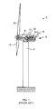
- One so-called horizontal-axis wind generator is schematically illustrated in Figure 1 and available from General Electric Company.
- This particular configuration for a wind turbine 2 includes a tower 4 supporting a nacelle 6 enclosing a drive train 8.
- the blades 10 are arranged on a hub to form a "rotor" at one end of the drive train 8 outside of the nacelle 6.
- the rotating blades 10 drive a gearbox 12 connected to an electrical generator 14 at the other end of the drive train 8 arranged inside the nacelle 6 along with a control system 16 that receives input from an anemometer 18.
- the blades 10 generate lift and capture momentum from moving air that is them imparted to a rotor as the blades spin in the "rotor plane.”
- Each blade is typically secured at its “root” end, and then “spans” radially “outboard” to a free, “tip” end. The distance from the tip to the root, at the opposite end of the blade, is called the “span.”
- the front, or “leading edge,” of the blade connects the forward-most points of the blade that first contact the air.
- the rear, or “trailing edge,” of the blade is where airflow that has been separated by the leading edge rejoins after passing over the suction and pressure surfaces of the blade.
- the blades 10 for such wind turbines 2 are typically fabricated by securing various "shell” and/or “rib” portions to one or more “spar” members extending spanwise along the inside of the blade for carrying most of the weight and aerodynamic forces on the blade.
- the spars are typically configured as I-shaped beams having a web, referred to as a "shear web” 20, extending between two flanges, referred to as “caps” or “spar caps,” that are secured to the inside of the suction and pressure surfaces of the blade.
- shear web configurations may also be used including, but not limited to "C-,” “L-,” “T-,” “X-,” “K-,” and/or box-shaped beams, and the shear webs 20 may also be utilized without caps.
- U.S. Patent No. 4,295,790 discloses a blade structure for use in a windmill with metal shear webs and subassemblies that are filled with approximately two pound cubic foot density rigid urethane foam.
- shear webs typically consist of a foam core that is coated by a resin-infused composite material.
- the core is typically formed from multiple foam sheets that are connected with adhesive and then trimmed to form the desired shape of the shear webs 20. These connected foam sheets inside of the shear web then act as a spacer for the composite material coatings on either side but do not provide much additional structural benefit to the shear web 20.
- a method of producing a shear web for a wind turbine blade including providing a mold generally conforming to the shape of at least a portion of a shear web; and filling the mold with a closed cell structural foam. Also provided is a wind turbine blade including a shear web having a joint-free closed cell structural foam core.
- FIGs. are not necessarily drawn to scale, but use the same reference numerals to designate corresponding parts throughout each of the several views, and in which:
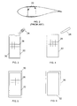
- FIG. 3 illustrates a schematic cross-sectional view of a female mold 22 for use in forming a shear web 20 for a wind turbine blade 10.
- the mold 22 generally conforms to the shape of the shear web and is filled or otherwise loaded with a liquid material, such as an expanding foam like a closed cell structural foam.
- a liquid material such as an expanding foam like a closed cell structural foam.
- the liquid structural foam may be sprayed into the mold 22 via a nozzle 24 or other device.
- the foam will typically expand to the edges of the mold 22 and out any openings of the mold.
- the mold 22 may be provided with or without any such openings.
- Optional reinforcing material 26 can also be added to the mold 22 in either a unidirectional or multi-directional pattern prior to spraying foam in order to increase the strength of the shear web 20.
- the reinforcing material 25 may include loose fibers, netted fibers, composites, and/or other materials.
- the reinforcing material 25 may also include a reinforcing structure. Once the foam has cured, any excess material may be removed from any openings of the mold 22 using a knife 28 or other suitable tool as shown in FIG. 4 .
- the molded and/or reinforced shear web consisting of foam and other structural material can then be wrapped or otherwise coated with a composite or structural fabric 30 or other material that is infused with a resin matrix in order to add the structural capacity to the shear web 20.
- the structural fabric 30 may also be infused with the resin matrix before or after it is wrapped and the structural fabric may be laminated onto the surface or infused with the resin matrix after it is wrapped.
- the mold 22 may be lined with a composite or structural fabric 30, as shown in FIG. 3 , that is infused prior to adding the reinforcing material 26 material and spraying the foam, leaving only the task of capping the cured shear web 20 with other composite material in order to form the shear web shape.
- Any structural fabric 30 in the mold may also be infused with resin after it is removed from the mold 20 on the least partially cured foam.
- the molded and/or reinforced shear web core my be implemented using a male mold 32 as shown in FIG. 6 .
- the male mold 32 generally conforms to the shape of the shear web core.
- Resin impregnated structural fabric 30 is loaded onto the outside of the male mold 32 in order to form the skin of the shear web 20. Slots may be provided in the surface of the male mold 32 for helping to disperse resin in the structural fabric 30.
- the shear web skin can be filled with a liquid material, such as an expanding foam like a closed cell structural foam, and any reinforcing material 26 in a similar manner to that shown in FIGs 3 and 4 .
- the male mold 32 may also take the form of spacers or other structural material to which laminate sheets are applied. Resin impregnated structural fabric 30 is then applied to the top or bottom edges of the spaced sheets in order to form the remaining skin of the shear web 20. Once cured, the shear web skin can be filled with a liquid material, such as an expanding foam like a closed cell structural foam, and any reinforcing material 26 in a similar manner to that shown in FIG.s 3 and 4 .
- a liquid material such as an expanding foam like a closed cell structural foam, and any reinforcing material 26 in a similar manner to that shown in FIG.s 3 and 4 .
- the technology described above provides various advantages over conventional approaches. For example, it helps provide tighter dimensional tolerances for the shear web 20 by eliminating the need to cut and position multiple foam sheet cores in a manual process that is time-consuming and prone to error. Any such dimensional discrepancies in the shear web can also lead to poor fitting of other components and/or other structural deficiencies in the blade 10. Given a reasonable cure time, spraying the foam into a mold is generally a faster process than cutting sheets and gluing them together in the appropriate shape. Scrap material waste is also reduced since any trimming only needs to be performed on material which protrudes from the top of the mold.
- reinforcing material 26 helps to adds structural properties to the foam material that would otherwise not be provided by a simple spacer between the structural composite materials on the outside of the shear web.
- the process also offers improved structural integrity since the interior of the shear web 20 is no longer made up of multiple sheets. Furthermore, it eliminates the manual or automated process of cutting and gluing sheets of foam to form the shape of the shear web 20, and enables shear webs to be provided with greater thickness and/or a higher strength to thickness ratio, than might otherwise be available using conventional approaches. This, in turn, reduces the weight of the overall blade system.
Landscapes
- Engineering & Computer Science (AREA)
- Life Sciences & Earth Sciences (AREA)
- Sustainable Development (AREA)
- Sustainable Energy (AREA)
- Chemical & Material Sciences (AREA)
- Combustion & Propulsion (AREA)
- Mechanical Engineering (AREA)
- General Engineering & Computer Science (AREA)
- Wind Motors (AREA)
- Moulding By Coating Moulds (AREA)
Abstract
Description
- The subject matter described here generally relates to fluid reaction surfaces with specific blade structures that are formed with a main spar, and, more particularly, to wind turbine blades having molded shear webs.
- A wind turbine is a machine for converting the kinetic energy in wind into mechanical energy. If the mechanical energy is used directly by the machinery, such as to pump water or to grind wheat, then the wind turbine may be referred to as a windmill. Similarly, if the mechanical energy is converted to electricity, then the machine may also be referred to as a wind generator or wind power plant.
- Wind turbines are typically categorized according to the vertical or horizontal axis about which the blades rotate. One so-called horizontal-axis wind generator is schematically illustrated in
Figure 1 and available from General Electric Company. This particular configuration for awind turbine 2 includes atower 4 supporting anacelle 6 enclosing a drive train 8. Theblades 10 are arranged on a hub to form a "rotor" at one end of the drive train 8 outside of thenacelle 6. The rotatingblades 10 drive agearbox 12 connected to an electrical generator 14 at the other end of the drive train 8 arranged inside thenacelle 6 along with acontrol system 16 that receives input from ananemometer 18. - The
blades 10 generate lift and capture momentum from moving air that is them imparted to a rotor as the blades spin in the "rotor plane." Each blade is typically secured at its "root" end, and then "spans" radially "outboard" to a free, "tip" end. The distance from the tip to the root, at the opposite end of the blade, is called the "span." The front, or "leading edge," of the blade connects the forward-most points of the blade that first contact the air. The rear, or "trailing edge," of the blade is where airflow that has been separated by the leading edge rejoins after passing over the suction and pressure surfaces of the blade. - As illustrated in
FIG. 2 , theblades 10 forsuch wind turbines 2 are typically fabricated by securing various "shell" and/or "rib" portions to one or more "spar" members extending spanwise along the inside of the blade for carrying most of the weight and aerodynamic forces on the blade. The spars are typically configured as I-shaped beams having a web, referred to as a "shear web" 20, extending between two flanges, referred to as "caps" or "spar caps," that are secured to the inside of the suction and pressure surfaces of the blade. However, other shear web configurations may also be used including, but not limited to "C-," "L-," "T-," "X-," "K-," and/or box-shaped beams, and theshear webs 20 may also be utilized without caps. For example,U.S. Patent No. 4,295,790 discloses a blade structure for use in a windmill with metal shear webs and subassemblies that are filled with approximately two pound cubic foot density rigid urethane foam. - Other conventional shear webs typically consist of a foam core that is coated by a resin-infused composite material. The core is typically formed from multiple foam sheets that are connected with adhesive and then trimmed to form the desired shape of the
shear webs 20. These connected foam sheets inside of the shear web then act as a spacer for the composite material coatings on either side but do not provide much additional structural benefit to theshear web 20. - Various drawbacks associated with such conventional approaches are addressed here in by providing, in various embodiments, a method of producing a shear web for a wind turbine blade, including providing a mold generally conforming to the shape of at least a portion of a shear web; and filling the mold with a closed cell structural foam. Also provided is a wind turbine blade including a shear web having a joint-free closed cell structural foam core.
- Various aspects of this technology will now be described with reference to the following figures ("FIGs.") which are not necessarily drawn to scale, but use the same reference numerals to designate corresponding parts throughout each of the several views, and in which:
-
FIG. 1 is a schematic side view of a conventional wind generator. -
FIG. 2 is a schematic cross-sectional view of the blade shown inFIG. 1 . -
FIG. 3 is schematic cross-sectional view of a female mold for a shear web of a wind turbine blade. -
FIG. 4 is a schematic cross-sectional view of a female mold for a shear web of a wind turbine blade. -
FIG. 5 is a schematic cross-sectional view of a molded shear web for a wind turbine blade. -
FIG. 6 is a schematic cross-sectional view of a male mold for a shear web of a wind turbine blade. -
FIG. 3 illustrates a schematic cross-sectional view of afemale mold 22 for use in forming ashear web 20 for awind turbine blade 10. Themold 22 generally conforms to the shape of the shear web and is filled or otherwise loaded with a liquid material, such as an expanding foam like a closed cell structural foam. For example, the liquid structural foam may be sprayed into themold 22 via anozzle 24 or other device. The foam will typically expand to the edges of themold 22 and out any openings of the mold. However, themold 22 may be provided with or without any such openings. - Optional reinforcing
material 26 can also be added to themold 22 in either a unidirectional or multi-directional pattern prior to spraying foam in order to increase the strength of theshear web 20. For example, the reinforcing material 25 may include loose fibers, netted fibers, composites, and/or other materials. The reinforcing material 25 may also include a reinforcing structure. Once the foam has cured, any excess material may be removed from any openings of themold 22 using aknife 28 or other suitable tool as shown inFIG. 4 . - As illustrated in
FIG. 5 , the molded and/or reinforced shear web consisting of foam and other structural material can then be wrapped or otherwise coated with a composite orstructural fabric 30 or other material that is infused with a resin matrix in order to add the structural capacity to theshear web 20. Thestructural fabric 30 may also be infused with the resin matrix before or after it is wrapped and the structural fabric may be laminated onto the surface or infused with the resin matrix after it is wrapped. Alternatively, or in addition, themold 22 may be lined with a composite orstructural fabric 30, as shown inFIG. 3 , that is infused prior to adding the reinforcingmaterial 26 material and spraying the foam, leaving only the task of capping the curedshear web 20 with other composite material in order to form the shear web shape. Anystructural fabric 30 in the mold may also be infused with resin after it is removed from themold 20 on the least partially cured foam. - In addition to the
female mold 22 shown inFIGs 3-5 , the molded and/or reinforced shear web core my be implemented using amale mold 32 as shown inFIG. 6 . Themale mold 32 generally conforms to the shape of the shear web core. Resin impregnatedstructural fabric 30 is loaded onto the outside of themale mold 32 in order to form the skin of theshear web 20. Slots may be provided in the surface of themale mold 32 for helping to disperse resin in thestructural fabric 30. Once cured and removed from the mold, the shear web skin can be filled with a liquid material, such as an expanding foam like a closed cell structural foam, and any reinforcingmaterial 26 in a similar manner to that shown inFIGs 3 and 4 . - The
male mold 32 may also take the form of spacers or other structural material to which laminate sheets are applied. Resin impregnatedstructural fabric 30 is then applied to the top or bottom edges of the spaced sheets in order to form the remaining skin of theshear web 20. Once cured, the shear web skin can be filled with a liquid material, such as an expanding foam like a closed cell structural foam, and any reinforcingmaterial 26 in a similar manner to that shown inFIG.s 3 and 4 - The technology described above provides various advantages over conventional approaches. For example, it helps provide tighter dimensional tolerances for the
shear web 20 by eliminating the need to cut and position multiple foam sheet cores in a manual process that is time-consuming and prone to error. Any such dimensional discrepancies in the shear web can also lead to poor fitting of other components and/or other structural deficiencies in theblade 10. Given a reasonable cure time, spraying the foam into a mold is generally a faster process than cutting sheets and gluing them together in the appropriate shape. Scrap material waste is also reduced since any trimming only needs to be performed on material which protrudes from the top of the mold. - The technology described above also provides improved structural properties so as to enable the further reduction of material in the skin portion of the blade. For example, reinforcing
material 26 helps to adds structural properties to the foam material that would otherwise not be provided by a simple spacer between the structural composite materials on the outside of the shear web. The process also offers improved structural integrity since the interior of theshear web 20 is no longer made up of multiple sheets. Furthermore, it eliminates the manual or automated process of cutting and gluing sheets of foam to form the shape of theshear web 20, and enables shear webs to be provided with greater thickness and/or a higher strength to thickness ratio, than might otherwise be available using conventional approaches. This, in turn, reduces the weight of the overall blade system. - It should be emphasized that the embodiments described above, and particularly any "preferred" embodiments, are merely examples of various implementations that have been set forth here to provide a clear understanding of various aspects of this technology. One of ordinary skill will be able to alter many of these embodiments without substantially departing from scope of protection defined solely by the proper construction of the following claims.
- Various aspects and embodiments of the present invention are now defined by the following numbered clauses:
- 1. A method of producing a shear web for a wind turbine blade, comprising:
- providing a mold generally conforming to a shape of at least a portion of a shear web; and
- filling the mold with a closed cell structural foam.
- 2. The method recited in clause 1, further comprising adding a reinforcing material to the mold.
- 3. The method recited in any preceding clause, further comprising lining the mold with a structural fabric.
- 4. The method recited in any preceding clause, further comprising:
- allowing the closed cell structural foam to at least partially cure in the mold;
- removing the at least partially cured closed cell structural foam from the mold; and
- wrapping the removed and at least partial cured closed cell structural foam in a structural fabric that is infused with a resin matrix.
- 5. The method recited in any preceding clause, further comprising lining the mold with a structural fabric.
- 6. The method recited in any preceding clause, further comprising:
- allowing the closed cell structural foam to at least partially cure in the mold;
- removing the at least partially cured closed cell structural foam from the mold; and
- wrapping the removed and at least partial cured closed cell structural foam in a structural fabric that is infused with a resin matrix.
- 7. A method of producing a shear web for a wind turbine blade, comprising:
- providing a mold generally conforming to a shape of at least a portion of a shear web;
- at least partially covering the mold with a resin impregnated structural fabric;
- at least partially curing the resin impregnated structural fabric;
- removing the cured resin impregnated structural fabric from the mold; and
- filling the removed resin impregnated structural fabric with a closed cell structural foam.
- 8. The method recited in any preceding clause, further comprising adding a reinforcing material to the closed cell structural foam.
- 9. A wind turbine blade comprising a shear web having a joint-free closed cell structural foam core.
- 10. The wind turbine blade recited in clause 9, wherein the shear web comprises a resin-infused structural fabric skin.
- 11. The wind turbine blade recited in
clause 9 or 10, wherein the shear web comprises a reinforcing material arranged in the closed cell structural foam core. - 12. The wind turbine blade recited in any of clauses 9 to 11, wherein in the shear web comprises a reinforcing material arranged in the closed cell structural foam core.
Claims (4)
- A method of producing a shear web (20) for a wind turbine blade (2), comprising:providing a mold (22, 32) generally conforming to a shape of at least a portion of a shear web (20); andfilling the mold (22) with a closed cell structural foam.
- The method recited in claim 1, further comprising adding a reinforcing material (26) to the mold (22).
- The method recited in claim 1 or 2, further comprising lining the mold (22) with a structural fabric (30).
- The method recited in claim 1, 2 or 3, further comprising:allowing the closed cell structural foam to at least partially cure in the mold (22);removing the at least partially cured closed cell structural foam from the mold (22); andwrapping the removed and at least partial cured closed cell structural foam in a structural fabric (30) that is infused with a resin matrix.
Applications Claiming Priority (1)
| Application Number | Priority Date | Filing Date | Title |
|---|---|---|---|
| US12/209,734 US7857595B2 (en) | 2008-09-12 | 2008-09-12 | Molded reinforced shear web cores |
Publications (3)
| Publication Number | Publication Date |
|---|---|
| EP2163759A2 true EP2163759A2 (en) | 2010-03-17 |
| EP2163759A3 EP2163759A3 (en) | 2016-07-27 |
| EP2163759B1 EP2163759B1 (en) | 2018-02-28 |
Family
ID=41626001
Family Applications (1)
| Application Number | Title | Priority Date | Filing Date |
|---|---|---|---|
| EP09168546.1A Not-in-force EP2163759B1 (en) | 2008-09-12 | 2009-08-25 | Molded reinforced shear web cores |
Country Status (3)
| Country | Link |
|---|---|
| US (1) | US7857595B2 (en) |
| EP (1) | EP2163759B1 (en) |
| CN (1) | CN101670635B (en) |
Cited By (1)
| Publication number | Priority date | Publication date | Assignee | Title |
|---|---|---|---|---|
| CN111037807A (en) * | 2019-11-28 | 2020-04-21 | 上海华宜风电模具有限公司 | Manufacturing method of adjustable trial movable flange of wind power blade web plate die |
Families Citing this family (8)
| Publication number | Priority date | Publication date | Assignee | Title |
|---|---|---|---|---|
| CN101934564A (en) * | 2010-09-16 | 2011-01-05 | 三一电气有限责任公司 | Manufacturing method of shearing rib male mold, shearing rib male mold, female mold and blade |
| JP2013022834A (en) * | 2011-07-21 | 2013-02-04 | Mitsubishi Heavy Ind Ltd | Composite material of fiber-reinforced resin and lightweight core, and method and apparatus for producing the same |
| US9677538B2 (en) * | 2012-02-09 | 2017-06-13 | General Electric Company | Wind turbine rotor blade assembly with root extension panel and method of assembly |
| US9597821B2 (en) | 2012-09-27 | 2017-03-21 | General Electric Company | Frame assembly, mold, and method for forming rotor blade |
| CN104015247B (en) * | 2014-05-30 | 2016-07-06 | 西安交通大学 | The method that the sintering creep of Integral hollow turbo blade ceramic-mould core controls |
| US10690111B2 (en) | 2016-12-02 | 2020-06-23 | General Electric Company | Wind turbine rotor blade |
| US10828843B2 (en) | 2017-03-16 | 2020-11-10 | General Electric Company | Shear webs for wind turbine rotor blades and methods for manufacturing same |
| CN112776312A (en) * | 2020-12-29 | 2021-05-11 | 江苏华曼复合材料科技有限公司 | Automobile anti-collision beam and manufacturing method thereof |
Family Cites Families (7)
| Publication number | Priority date | Publication date | Assignee | Title |
|---|---|---|---|---|
| US4295790A (en) | 1979-06-21 | 1981-10-20 | The Budd Company | Blade structure for use in a windmill |
| GB2105633B (en) * | 1981-08-28 | 1985-07-31 | Dowty Rotol Ltd | Foam-containing structures |
| DK176335B1 (en) * | 2001-11-13 | 2007-08-20 | Siemens Wind Power As | Process for manufacturing wind turbine blades |
| CN100385114C (en) * | 2005-04-01 | 2008-04-30 | 同济大学 | Composite material wind turbine blade and preparation method thereof |
| DK1754886T3 (en) | 2005-08-17 | 2012-12-17 | Gen Electric | Rotor blade for a wind turbine |
| GB0613872D0 (en) * | 2006-07-12 | 2006-08-23 | Airbus Uk Ltd | Method of manufacturing composite part |
| EP1880833A1 (en) * | 2006-07-19 | 2008-01-23 | National University of Ireland, Galway | Composite articles comprising in-situ-polymerisable thermoplastic material and processes for their construction |
-
2008
- 2008-09-12 US US12/209,734 patent/US7857595B2/en not_active Expired - Fee Related
-
2009
- 2009-08-25 EP EP09168546.1A patent/EP2163759B1/en not_active Not-in-force
- 2009-09-11 CN CN200910175963.4A patent/CN101670635B/en not_active Expired - Fee Related
Cited By (1)
| Publication number | Priority date | Publication date | Assignee | Title |
|---|---|---|---|---|
| CN111037807A (en) * | 2019-11-28 | 2020-04-21 | 上海华宜风电模具有限公司 | Manufacturing method of adjustable trial movable flange of wind power blade web plate die |
Also Published As
| Publication number | Publication date |
|---|---|
| CN101670635A (en) | 2010-03-17 |
| EP2163759B1 (en) | 2018-02-28 |
| US7857595B2 (en) | 2010-12-28 |
| US20100068498A1 (en) | 2010-03-18 |
| EP2163759A3 (en) | 2016-07-27 |
| CN101670635B (en) | 2016-06-29 |
Similar Documents
| Publication | Publication Date | Title |
|---|---|---|
| EP2163759B1 (en) | Molded reinforced shear web cores | |
| US10273935B2 (en) | Rotor blades having structural skin insert and methods of making same | |
| CN101062594B (en) | Methods and apparatus for fabricating blades | |
| EP2186626A2 (en) | Method of making wind turbine blade | |
| US8250761B2 (en) | Methods of manufacturing rotor blades for a wind turbine | |
| EP2204577B1 (en) | Flatback insert for turbine blades | |
| EP2224127B1 (en) | Improved spar cap for wind turbine blades | |
| CN205330872U (en) | Rotor blade component and rotor blade | |
| US20090084932A1 (en) | Wind turbine blade molds | |
| US20180156190A1 (en) | Wind turbine rotor blade | |
| US11383454B2 (en) | Wind turbine blade manufacture | |
| EP2617555A1 (en) | Wind turbine rotor blade with trailing edge comprising rovings | |
| EP2159414B1 (en) | Wind turbine blades with cross webs | |
| US20120090789A1 (en) | Methods of manufacturing rotor blade tooling structures for wind turbines | |
| EP3032094B1 (en) | Spar cap for a wind turbine rotor blade | |
| EP4146457A1 (en) | Wind turbine blade | |
| EP2591902A2 (en) | Methods of manufacturing tooling structures and tooling structures | |
| KR102586818B1 (en) | Blade of wind turbine and manufacturing method of the same | |
| CN202545139U (en) | Deflection-resistant wind turbine wind wheel blade with reinforcing rib structure | |
| CN201679621U (en) | Glass reinforced plastic hollow blade with multi-beam structure for megawatt wind generator | |
| US11590718B2 (en) | Method of manufacturing a wind turbine blade | |
| Crudu | Aeolian blades wound spars design and modeling procedure |
Legal Events
| Date | Code | Title | Description |
|---|---|---|---|
| PUAI | Public reference made under article 153(3) epc to a published international application that has entered the european phase |
Free format text: ORIGINAL CODE: 0009012 |
|
| AK | Designated contracting states |
Kind code of ref document: A2 Designated state(s): AT BE BG CH CY CZ DE DK EE ES FI FR GB GR HR HU IE IS IT LI LT LU LV MC MK MT NL NO PL PT RO SE SI SK SM TR |
|
| AX | Request for extension of the european patent |
Extension state: AL BA RS |
|
| PUAL | Search report despatched |
Free format text: ORIGINAL CODE: 0009013 |
|
| AK | Designated contracting states |
Kind code of ref document: A3 Designated state(s): AT BE BG CH CY CZ DE DK EE ES FI FR GB GR HR HU IE IS IT LI LT LU LV MC MK MT NL NO PL PT RO SE SI SK SM TR |
|
| AX | Request for extension of the european patent |
Extension state: AL BA RS |
|
| RIC1 | Information provided on ipc code assigned before grant |
Ipc: F03D 3/06 20060101ALI20160621BHEP Ipc: F03D 1/06 20060101AFI20160621BHEP |
|
| 17P | Request for examination filed |
Effective date: 20170127 |
|
| RBV | Designated contracting states (corrected) |
Designated state(s): AT BE BG CH CY CZ DE DK EE ES FI FR GB GR HR HU IE IS IT LI LT LU LV MC MK MT NL NO PL PT RO SE SI SK SM TR |
|
| GRAP | Despatch of communication of intention to grant a patent |
Free format text: ORIGINAL CODE: EPIDOSNIGR1 |
|
| INTG | Intention to grant announced |
Effective date: 20171023 |
|
| GRAS | Grant fee paid |
Free format text: ORIGINAL CODE: EPIDOSNIGR3 |
|
| GRAA | (expected) grant |
Free format text: ORIGINAL CODE: 0009210 |
|
| AK | Designated contracting states |
Kind code of ref document: B1 Designated state(s): AT BE BG CH CY CZ DE DK EE ES FI FR GB GR HR HU IE IS IT LI LT LU LV MC MK MT NL NO PL PT RO SE SI SK SM TR |
|
| REG | Reference to a national code |
Ref country code: GB Ref legal event code: FG4D Ref country code: CH Ref legal event code: EP |
|
| REG | Reference to a national code |
Ref country code: AT Ref legal event code: REF Ref document number: 974445 Country of ref document: AT Kind code of ref document: T Effective date: 20180315 |
|
| REG | Reference to a national code |
Ref country code: IE Ref legal event code: FG4D |
|
| REG | Reference to a national code |
Ref country code: DE Ref legal event code: R096 Ref document number: 602009050952 Country of ref document: DE |
|
| REG | Reference to a national code |
Ref country code: NL Ref legal event code: MP Effective date: 20180228 |
|
| REG | Reference to a national code |
Ref country code: LT Ref legal event code: MG4D |
|
| REG | Reference to a national code |
Ref country code: AT Ref legal event code: MK05 Ref document number: 974445 Country of ref document: AT Kind code of ref document: T Effective date: 20180228 |
|
| PG25 | Lapsed in a contracting state [announced via postgrant information from national office to epo] |
Ref country code: NL Free format text: LAPSE BECAUSE OF FAILURE TO SUBMIT A TRANSLATION OF THE DESCRIPTION OR TO PAY THE FEE WITHIN THE PRESCRIBED TIME-LIMIT Effective date: 20180228 Ref country code: LT Free format text: LAPSE BECAUSE OF FAILURE TO SUBMIT A TRANSLATION OF THE DESCRIPTION OR TO PAY THE FEE WITHIN THE PRESCRIBED TIME-LIMIT Effective date: 20180228 Ref country code: ES Free format text: LAPSE BECAUSE OF FAILURE TO SUBMIT A TRANSLATION OF THE DESCRIPTION OR TO PAY THE FEE WITHIN THE PRESCRIBED TIME-LIMIT Effective date: 20180228 Ref country code: CY Free format text: LAPSE BECAUSE OF FAILURE TO SUBMIT A TRANSLATION OF THE DESCRIPTION OR TO PAY THE FEE WITHIN THE PRESCRIBED TIME-LIMIT Effective date: 20180228 Ref country code: FI Free format text: LAPSE BECAUSE OF FAILURE TO SUBMIT A TRANSLATION OF THE DESCRIPTION OR TO PAY THE FEE WITHIN THE PRESCRIBED TIME-LIMIT Effective date: 20180228 Ref country code: HR Free format text: LAPSE BECAUSE OF FAILURE TO SUBMIT A TRANSLATION OF THE DESCRIPTION OR TO PAY THE FEE WITHIN THE PRESCRIBED TIME-LIMIT Effective date: 20180228 Ref country code: NO Free format text: LAPSE BECAUSE OF FAILURE TO SUBMIT A TRANSLATION OF THE DESCRIPTION OR TO PAY THE FEE WITHIN THE PRESCRIBED TIME-LIMIT Effective date: 20180528 |
|
| PG25 | Lapsed in a contracting state [announced via postgrant information from national office to epo] |
Ref country code: AT Free format text: LAPSE BECAUSE OF FAILURE TO SUBMIT A TRANSLATION OF THE DESCRIPTION OR TO PAY THE FEE WITHIN THE PRESCRIBED TIME-LIMIT Effective date: 20180228 Ref country code: GR Free format text: LAPSE BECAUSE OF FAILURE TO SUBMIT A TRANSLATION OF THE DESCRIPTION OR TO PAY THE FEE WITHIN THE PRESCRIBED TIME-LIMIT Effective date: 20180529 Ref country code: BG Free format text: LAPSE BECAUSE OF FAILURE TO SUBMIT A TRANSLATION OF THE DESCRIPTION OR TO PAY THE FEE WITHIN THE PRESCRIBED TIME-LIMIT Effective date: 20180528 Ref country code: LV Free format text: LAPSE BECAUSE OF FAILURE TO SUBMIT A TRANSLATION OF THE DESCRIPTION OR TO PAY THE FEE WITHIN THE PRESCRIBED TIME-LIMIT Effective date: 20180228 Ref country code: SE Free format text: LAPSE BECAUSE OF FAILURE TO SUBMIT A TRANSLATION OF THE DESCRIPTION OR TO PAY THE FEE WITHIN THE PRESCRIBED TIME-LIMIT Effective date: 20180228 |
|
| PG25 | Lapsed in a contracting state [announced via postgrant information from national office to epo] |
Ref country code: RO Free format text: LAPSE BECAUSE OF FAILURE TO SUBMIT A TRANSLATION OF THE DESCRIPTION OR TO PAY THE FEE WITHIN THE PRESCRIBED TIME-LIMIT Effective date: 20180228 Ref country code: EE Free format text: LAPSE BECAUSE OF FAILURE TO SUBMIT A TRANSLATION OF THE DESCRIPTION OR TO PAY THE FEE WITHIN THE PRESCRIBED TIME-LIMIT Effective date: 20180228 Ref country code: PL Free format text: LAPSE BECAUSE OF FAILURE TO SUBMIT A TRANSLATION OF THE DESCRIPTION OR TO PAY THE FEE WITHIN THE PRESCRIBED TIME-LIMIT Effective date: 20180228 Ref country code: IT Free format text: LAPSE BECAUSE OF FAILURE TO SUBMIT A TRANSLATION OF THE DESCRIPTION OR TO PAY THE FEE WITHIN THE PRESCRIBED TIME-LIMIT Effective date: 20180228 |
|
| REG | Reference to a national code |
Ref country code: DE Ref legal event code: R097 Ref document number: 602009050952 Country of ref document: DE |
|
| PG25 | Lapsed in a contracting state [announced via postgrant information from national office to epo] |
Ref country code: SM Free format text: LAPSE BECAUSE OF FAILURE TO SUBMIT A TRANSLATION OF THE DESCRIPTION OR TO PAY THE FEE WITHIN THE PRESCRIBED TIME-LIMIT Effective date: 20180228 Ref country code: SK Free format text: LAPSE BECAUSE OF FAILURE TO SUBMIT A TRANSLATION OF THE DESCRIPTION OR TO PAY THE FEE WITHIN THE PRESCRIBED TIME-LIMIT Effective date: 20180228 Ref country code: DK Free format text: LAPSE BECAUSE OF FAILURE TO SUBMIT A TRANSLATION OF THE DESCRIPTION OR TO PAY THE FEE WITHIN THE PRESCRIBED TIME-LIMIT Effective date: 20180228 Ref country code: CZ Free format text: LAPSE BECAUSE OF FAILURE TO SUBMIT A TRANSLATION OF THE DESCRIPTION OR TO PAY THE FEE WITHIN THE PRESCRIBED TIME-LIMIT Effective date: 20180228 |
|
| PLBE | No opposition filed within time limit |
Free format text: ORIGINAL CODE: 0009261 |
|
| STAA | Information on the status of an ep patent application or granted ep patent |
Free format text: STATUS: NO OPPOSITION FILED WITHIN TIME LIMIT |
|
| 26N | No opposition filed |
Effective date: 20181129 |
|
| PG25 | Lapsed in a contracting state [announced via postgrant information from national office to epo] |
Ref country code: SI Free format text: LAPSE BECAUSE OF FAILURE TO SUBMIT A TRANSLATION OF THE DESCRIPTION OR TO PAY THE FEE WITHIN THE PRESCRIBED TIME-LIMIT Effective date: 20180228 |
|
| REG | Reference to a national code |
Ref country code: DE Ref legal event code: R119 Ref document number: 602009050952 Country of ref document: DE |
|
| PG25 | Lapsed in a contracting state [announced via postgrant information from national office to epo] |
Ref country code: MC Free format text: LAPSE BECAUSE OF FAILURE TO SUBMIT A TRANSLATION OF THE DESCRIPTION OR TO PAY THE FEE WITHIN THE PRESCRIBED TIME-LIMIT Effective date: 20180228 |
|
| REG | Reference to a national code |
Ref country code: CH Ref legal event code: PL |
|
| GBPC | Gb: european patent ceased through non-payment of renewal fee |
Effective date: 20180825 |
|
| PG25 | Lapsed in a contracting state [announced via postgrant information from national office to epo] |
Ref country code: CH Free format text: LAPSE BECAUSE OF NON-PAYMENT OF DUE FEES Effective date: 20180831 Ref country code: LI Free format text: LAPSE BECAUSE OF NON-PAYMENT OF DUE FEES Effective date: 20180831 Ref country code: LU Free format text: LAPSE BECAUSE OF NON-PAYMENT OF DUE FEES Effective date: 20180825 |
|
| REG | Reference to a national code |
Ref country code: BE Ref legal event code: MM Effective date: 20180831 |
|
| PG25 | Lapsed in a contracting state [announced via postgrant information from national office to epo] |
Ref country code: DE Free format text: LAPSE BECAUSE OF NON-PAYMENT OF DUE FEES Effective date: 20190301 |
|
| PG25 | Lapsed in a contracting state [announced via postgrant information from national office to epo] |
Ref country code: BE Free format text: LAPSE BECAUSE OF NON-PAYMENT OF DUE FEES Effective date: 20180831 Ref country code: FR Free format text: LAPSE BECAUSE OF NON-PAYMENT OF DUE FEES Effective date: 20180831 |
|
| PG25 | Lapsed in a contracting state [announced via postgrant information from national office to epo] |
Ref country code: GB Free format text: LAPSE BECAUSE OF NON-PAYMENT OF DUE FEES Effective date: 20180825 |
|
| PG25 | Lapsed in a contracting state [announced via postgrant information from national office to epo] |
Ref country code: MT Free format text: LAPSE BECAUSE OF NON-PAYMENT OF DUE FEES Effective date: 20180825 |
|
| PG25 | Lapsed in a contracting state [announced via postgrant information from national office to epo] |
Ref country code: TR Free format text: LAPSE BECAUSE OF FAILURE TO SUBMIT A TRANSLATION OF THE DESCRIPTION OR TO PAY THE FEE WITHIN THE PRESCRIBED TIME-LIMIT Effective date: 20180228 |
|
| PG25 | Lapsed in a contracting state [announced via postgrant information from national office to epo] |
Ref country code: PT Free format text: LAPSE BECAUSE OF FAILURE TO SUBMIT A TRANSLATION OF THE DESCRIPTION OR TO PAY THE FEE WITHIN THE PRESCRIBED TIME-LIMIT Effective date: 20180228 Ref country code: HU Free format text: LAPSE BECAUSE OF FAILURE TO SUBMIT A TRANSLATION OF THE DESCRIPTION OR TO PAY THE FEE WITHIN THE PRESCRIBED TIME-LIMIT; INVALID AB INITIO Effective date: 20090825 |
|
| PG25 | Lapsed in a contracting state [announced via postgrant information from national office to epo] |
Ref country code: MK Free format text: LAPSE BECAUSE OF NON-PAYMENT OF DUE FEES Effective date: 20180228 Ref country code: IE Free format text: LAPSE BECAUSE OF NON-PAYMENT OF DUE FEES Effective date: 20180825 |
|
| PG25 | Lapsed in a contracting state [announced via postgrant information from national office to epo] |
Ref country code: IS Free format text: LAPSE BECAUSE OF FAILURE TO SUBMIT A TRANSLATION OF THE DESCRIPTION OR TO PAY THE FEE WITHIN THE PRESCRIBED TIME-LIMIT Effective date: 20180628 |
|
| P01 | Opt-out of the competence of the unified patent court (upc) registered |
Effective date: 20230522 |