EP2163738A1 - Breather device for engine - Google Patents
Breather device for engine Download PDFInfo
- Publication number
- EP2163738A1 EP2163738A1 EP08790973A EP08790973A EP2163738A1 EP 2163738 A1 EP2163738 A1 EP 2163738A1 EP 08790973 A EP08790973 A EP 08790973A EP 08790973 A EP08790973 A EP 08790973A EP 2163738 A1 EP2163738 A1 EP 2163738A1
- Authority
- EP
- European Patent Office
- Prior art keywords
- blow
- breather chamber
- gas inlet
- head cover
- breather
- Prior art date
- Legal status (The legal status is an assumption and is not a legal conclusion. Google has not performed a legal analysis and makes no representation as to the accuracy of the status listed.)
- Withdrawn
Links
Images


Classifications
-
- F—MECHANICAL ENGINEERING; LIGHTING; HEATING; WEAPONS; BLASTING
- F01—MACHINES OR ENGINES IN GENERAL; ENGINE PLANTS IN GENERAL; STEAM ENGINES
- F01M—LUBRICATING OF MACHINES OR ENGINES IN GENERAL; LUBRICATING INTERNAL COMBUSTION ENGINES; CRANKCASE VENTILATING
- F01M13/00—Crankcase ventilating or breathing
- F01M13/04—Crankcase ventilating or breathing having means for purifying air before leaving crankcase, e.g. removing oil
- F01M13/0416—Crankcase ventilating or breathing having means for purifying air before leaving crankcase, e.g. removing oil arranged in valve-covers
-
- F—MECHANICAL ENGINEERING; LIGHTING; HEATING; WEAPONS; BLASTING
- F01—MACHINES OR ENGINES IN GENERAL; ENGINE PLANTS IN GENERAL; STEAM ENGINES
- F01M—LUBRICATING OF MACHINES OR ENGINES IN GENERAL; LUBRICATING INTERNAL COMBUSTION ENGINES; CRANKCASE VENTILATING
- F01M13/00—Crankcase ventilating or breathing
- F01M13/02—Crankcase ventilating or breathing by means of additional source of positive or negative pressure
- F01M13/021—Crankcase ventilating or breathing by means of additional source of positive or negative pressure of negative pressure
- F01M13/022—Crankcase ventilating or breathing by means of additional source of positive or negative pressure of negative pressure using engine inlet suction
-
- F—MECHANICAL ENGINEERING; LIGHTING; HEATING; WEAPONS; BLASTING
- F01—MACHINES OR ENGINES IN GENERAL; ENGINE PLANTS IN GENERAL; STEAM ENGINES
- F01M—LUBRICATING OF MACHINES OR ENGINES IN GENERAL; LUBRICATING INTERNAL COMBUSTION ENGINES; CRANKCASE VENTILATING
- F01M13/00—Crankcase ventilating or breathing
- F01M13/04—Crankcase ventilating or breathing having means for purifying air before leaving crankcase, e.g. removing oil
- F01M2013/0433—Crankcase ventilating or breathing having means for purifying air before leaving crankcase, e.g. removing oil with a deflection device, e.g. screen
-
- F—MECHANICAL ENGINEERING; LIGHTING; HEATING; WEAPONS; BLASTING
- F01—MACHINES OR ENGINES IN GENERAL; ENGINE PLANTS IN GENERAL; STEAM ENGINES
- F01M—LUBRICATING OF MACHINES OR ENGINES IN GENERAL; LUBRICATING INTERNAL COMBUSTION ENGINES; CRANKCASE VENTILATING
- F01M13/00—Crankcase ventilating or breathing
- F01M13/04—Crankcase ventilating or breathing having means for purifying air before leaving crankcase, e.g. removing oil
- F01M2013/0455—Crankcase ventilating or breathing having means for purifying air before leaving crankcase, e.g. removing oil with a de-icing or defrosting system
-
- F—MECHANICAL ENGINEERING; LIGHTING; HEATING; WEAPONS; BLASTING
- F01—MACHINES OR ENGINES IN GENERAL; ENGINE PLANTS IN GENERAL; STEAM ENGINES
- F01M—LUBRICATING OF MACHINES OR ENGINES IN GENERAL; LUBRICATING INTERNAL COMBUSTION ENGINES; CRANKCASE VENTILATING
- F01M13/00—Crankcase ventilating or breathing
- F01M13/04—Crankcase ventilating or breathing having means for purifying air before leaving crankcase, e.g. removing oil
- F01M2013/0472—Crankcase ventilating or breathing having means for purifying air before leaving crankcase, e.g. removing oil using heating means
Definitions
- the present invention relates to a breather device for an engine in which a breather chamber is disposed in the interior of a head cover joined to an engine cylinder head, and oil contained in blow-by gas returning to an intake system via the breather chamber is separated, a predetermined gap being formed between an outer surface of the breather chamber and an inner surface of the head cover.
- Patent Publication 1 Japanese Utility Model Registration Publication No. 6-25623
- the present invention has been accomplished in the light of the above-mentioned circumstances, and it is an object thereof to reliably prevent oil from entering the interior of a breather chamber from a blow-by gas inlet while preventing blow-by gas from freezing in the interior of the breather chamber.
- a breather device for an engine in which a breather chamber is disposed in the interior of a head cover joined to an engine cylinder head, and oil contained in blow-by gas returning to an intake system via the breather chamber is separated, a predetermined gap being formed between an outer surface of the breather chamber and an inner surface of the head cover, characterized in that a blow-by gas inlet formed in a wall face of the breather chamber opens at a position that faces an inner surface of the head cover.
- a recess in which a combustion chamber interior inserted member is disposed is formed in an upper wall of the head cover, the breather chamber is disposed at a position that avoids the recess, and the blow-by gas inlet opens at a position that faces an inner surface of the recess.
- a third aspect of the present invention in addition to the first or second aspect, when an area around a camshaft that is disposed beneath the breather chamber and is the closest to the blow-by gas inlet is divided by a plane that contains an axis of the camshaft and is parallel to a cylinder axis into a first region on the side where the tip of a cam passes through from bottom to top and a second region on the side where the tip of the cam passes through from top to bottom, the blow-by gas inlet opens in the second region.
- a minimum distance between the inner surface of the head cover and the outer surface of the breather chamber is set smaller than a vertical length of the blow-by gas inlet at a position in which the blow-by gas inlet is formed.
- the breather chamber communicates with a blow-by gas outlet passage, and the area of an opening of the blow-by gas inlet is formed larger than the area of the minimum passage cross-section of the blow-by gas outlet passage.
- An exhaust camshaft 23 of an embodiment corresponds to the camshaft of the present invention
- an exhaust cam 25 of the embodiment corresponds to the cam of the present invention
- an injector 29 of the embodiment corresponds to the combustion chamber interior inserted member of the present invention
- a blow-by gas outlet 31 and coupling 13c of the embodiment correspond to the blow-by gas outlet passage of the present invention.
- the predetermined gap is formed between the outer surface of the breather chamber disposed in the interior of the head cover and the inner surface of the head cover, even if the outside temperature decreases, the gap functions as an insulating space, thereby preventing blow-by gas from freezing.
- blow-by gas inlet formed in the wall face of the breather chamber is made to open at a position that faces the inner surface of the head cover, compared with a case in which a blow-by gas inlet is made to open in a lower face of the breather chamber, not only can the degree of freedom for the position of the blow-by gas inlet be increased, but it is also possible for an effect in separating oil by means of the gap between the breather chamber and the head cover to be exhibited, thereby preventing oil from entering the breather chamber.
- the breather chamber is disposed at a position that avoids the recess formed on the upper wall of the head cover, and the blow-by gas inlet is made to open at a position facing the inner surface of the recess, it is possible to make the breather chamber have a complex shape, thereby enhancing the effect in separating oil.
- the blow-by gas inlet is disposed on the opposite side to the side where the cam splashes up oil due to rotation of the camshaft, and it is possible to minimize the amount of oil entering the interior of the breather chamber.
- the minimum distance between the inner surface of the head cover and the outer surface of the breather chamber at the position where the blow-by gas inlet is formed is set smaller than the vertical length of the blow-by gas inlet, it is possible to exhibit an effect in separating oil by narrowing the passage for the blow-by gas prior to the blow-by gas inlet.
- the area of the opening of the blow-by gas inlet of the breather chamber is set larger than the area of the minimum passage cross-section of the blow-by gas outlet passage, it is possible to reduce the flow rate of the blow-by gas flowing into the blow-by gas inlet and make it difficult for oil to enter the interior of the breather chamber together with the blow-by gas.
- FIG. 1 to FIG. 8 show an embodiment of the present invention.
- a cylinder head 12 is joined to the upper end of a cylinder block 11, and a head cover 13 is joined to the upper end of the cylinder head 12.
- the vertical direction is defined such that the cylinder block 11 side is the lower side, and the head cover 13 side is the upper side.
- a combustion chamber 14 Formed in the cylinder head 12 are a combustion chamber 14, and an intake port 15 and an exhaust port 16 communicating with the combustion chamber 14, the intake port 15 being opened and closed by an intake valve 17 and the exhaust port 16 being opened and closed by an exhaust valve 18.
- a camshaft holder 19 and a cap 20 are superimposed on an upper face of the cylinder head 12 and secured by means of a plurality of bolts 21, and an intake cam 24 and an exhaust cam 25 are provided respectively on an intake camshaft 22 and an exhaust camshaft 23 rotatably supported between the camshaft holder 19 and the cap 20.
- a breather chamber 26 is disposed between an upper face of the cap 20 and a lower face of the head cover 13.
- the breather chamber 26 is made of a synthetic resin, and is formed by joining a breather chamber main body 27 on the upper side and a cover plate 28 on the lower side.
- the structure of the breather chamber 26 is now explained by reference to FIG. 2 to FIG. 8 .
- a recess 13a that is recessed toward the cylinder head 12 side along a crankshaft axis L1 is formed in a central part of the head cover 13, which has an open lower face, and four injectors 29 (see FIG. 1 and FIG. 2 ) are disposed therein.
- the breather chamber 26 is substantially U-shaped overall; a blow-by gas inlet 30 is formed at one end, and a blow-by gas outlet 31 is formed at the other end.
- An annular space is formed in the interior of the head cover 13 between an outer peripheral wall thereof and the recess 13a, and the U-shaped breather chamber 26 is disposed in this space.
- the breather chamber main body 27 is a trough-shaped member having an open lower face, and the open part is blocked by the plate-shaped cover plate 28. That is, a joining face 28a (section shown by light-colored shading) formed on the outer periphery of the cover plate 28 is joined by vibration welding to a joining flange 27a formed along the outer periphery of the breather chamber main body 27, thereby forming the breather chamber 26 in a tubular shape.
- a plurality (15 in the embodiment) of joining flanges 28b (section shown by dark-colored shading) are projectingly provided on the outside of the joining face 28a of the cover plate 28 in an adjacent state, and these joining flames 28b are vibration welded to joining faces 13b (see FIG. 5 ) on the inner surface of the head cover 13.
- the joining faces 13b of the head cover are also shown by shading in FIG. 3 .
- a gap ⁇ (see FIG. 1 , FIG. 5 to FIG. 7 ) for forming an insulating space is formed between the outer surface of the breather chamber main body 27 and the inner surface of the head cover 13.
- the blow-by gas inlet 30 formed at one end of the breather chamber main body 27 opens sideways.
- the blow-by gas outlet 31 formed at the other end of the breather chamber main body 27 opens upward, and an annular joining flange 27b is formed on the periphery thereof.
- An oil drop hole 28c is formed in an intermediate section of the cover plate 28, and paired first and second baffle plates 28d and 28e are provided as two pairs between the oil drop hole 28c and the blow-by gas inlet 30.
- a first hanging wall 27c and a second hanging wall 27d hang from an upper wall of the breather chamber main body 27; the first hanging wall 27c is formed in a comb shape separated into three, and the second hanging wall 27d has a large number of vertically extending ribs 27e formed on a face on the first hanging wall 27c side.
- the first baffle plate 28d, the first hanging wall 27c, the second baffle plate 28e and the second hanging wall 27d are disposed in turn, and they form a labyrinth 32 for suppressing the flow of blow-by gas. Two labyrinths 32 having the above arrangement are disposed in series.
- the blow-by gas inlet 30 of the breather chamber 26 opens sideways so as to face the inner surface of the recess 13a of the head cover 13.
- the exhaust camshaft 23, which is on the side close to the blow-by gas inlet 30 of the breather chamber 26, is disposed therebeneath, and the exhaust camshaft 23 rotates clockwise in FIG. 5 .
- a plane P passing through an axis L2 of the exhaust camshaft 23 and extending in the direction of a cylinder axis L3 as a reference in a first region R1 on the left side thereof the exhaust cam 25 rotates from bottom to top, and in a second region R2 on the right side thereof the exhaust cam 25 rotates from top to bottom.
- the blow-by gas inlet 30 of the breather chamber 26 opens in a direction away from the plane P in the second region R2.
- the joining flange 27b surrounding the blow-by gas outlet 31 of the breather chamber main body 27 is joined to a lower face of an upper wall of the head cover 13 by vibration welding.
- a coupling 13c is integrally formed on the breather chamber main body 27 in the vicinity of the blow-by gas outlet 31, and this coupling 13c is connected to an engine intake system via a breather hose, which is not illustrated.
- the area of an opening of the blow-by gas inlet 30 is set larger than the minimum passage cross-sectional area of the blow-by gas outlet passage, that is, the blow-by gas outlet 31 or the coupling 13c. This is because, since the quantity of flow of a fluid is the product of the flow path cross-sectional area and the flow rate, the larger the flow path cross-sectional area, the lower the flow rate can be made. It is therefore possible by ensuring a large area for the opening of the blow-by gas inlet 30 to reduce the flow rate of blow-by gas in this section and prevent effectively oil from entering the breather chamber 26 together with blow-by gas.
- the oil drop hole 28c formed in the cover plate 28 of the breather chamber 26 communicates with an oil pan, which is not illustrated, via an oil return passage 20a formed in the cap 20, an oil return passage 19a formed in the camshaft holder 19, an oil return passage 12a formed in the cylinder head 12, and an oil return passage 11a formed in the cylinder block 11.
- an oil return passage 20a formed in the cap 20 an oil return passage 19a formed in the camshaft holder 19
- an oil return passage 12a formed in the cylinder head 12a formed in the cylinder head 12
- a minimum distance X between the inner surface of the recess 13a of the head cover 13 and the outer surface of the breather chamber 26 is set smaller than a vertical length Y of the blow-by gas inlet 30.
- the breather chamber 26, to which blow-by gas is supplied is provided with the gap ⁇ , which functions as an insulating space, between itself and the head cover 13, it is possible to prevent blow-by gas within the breather chamber 26 from freezing when the outside temperature decreases, thereby avoiding blockage of the blow-by gas passage.
- Blow-by gas within the head cover 13 flows into the interior of the breather chamber 26 through the blow-by gas inlet 30 provided at one end of the breather chamber 26, which has a substantially U-shaped form, and since the blow-by gas inlet 30 opens sideways so as to face the inner surface of a side wall of the recess 13a of the head cover 13 rather than opening downward, even if the blow-by gas inlet 30 is formed large so as to reduce the flow rate of blow-by gas, it is possible to prevent effectively oil splashed up by a valve operating mechanism disposed beneath the breather chamber 26 from entering the interior of the breather chamber 26 through the blow-by gas inlet 30. Moreover, compared with a case in which the blow-by gas inlet 30 opens downward, the degree of freedom in layout of the blow-by gas inlet 30 can be enhanced.
- blow-by gas inlet 30 is disposed in the second region R2 in which the exhaust cam 25 provided on the exhaust camshaft 23 moves from top to bottom, that is, a region in which oil is not splashed up toward the breather chamber 26, it is possible to further reliably prevent oil from entering the breather chamber 26.
- the minimum distance X between the inner surface of the recess 13a of the head cover 13 and the outer surface of the breather chamber 26 is set smaller than the vertical length Y of the blow-by gas inlet 30, it becomes difficult for oil to enter between the inner surface of the recess 13a of the head cover 13 and the outer surface of the breather chamber 26, and it is thereby also possible to prevent oil from entering the breather chamber 26.
- blow-by gas that has flowed into the interior of the breather chamber 26 through the blow-by gas inlet 30 since the blow-by gas passes through the two labyrinths 32 and 32 (see FIG. 3 , FIG. 7 , and FIG. 8 ) while flowing through the interior of the breather chamber 26, oil is reliably separated from the blow-by gas.
- the oil that has been separated from blow-by gas flows along a bottom wall of the breather chamber 26 and is returned to the oil pan through the oil drop hole 28c (see FIG. 1 and FIG. 3 ) via the oil return passages 20a, 19a, 12a, and 11a.
- Blow-by gas from which oil has been separated as above further flows toward the blow-by gas outlet 31 through the interior of the breather chamber 26, and oil that has not been separated by the two labyrinths 32 and 32 is further separated here.
- the shape of the breather chamber 26 is a U shape that surrounds the recess 13a formed in a central part of the head cover 13, the shape of the breather chamber 26 is complex, thus promoting separation of oil.
- Blow-by gas from which oil has finally been separated returns to the engine intake system from the blow-by gas outlet 31 via the coupling 13c and the breather hose, which is not illustrated.
- a direct fuel-injection engine is illustrated, but the present invention may be applied to both a gasoline engine and a diesel engine, and may also be applied to a port-injection type gasoline engine.
- an ignition plug becomes the combustion chamber interior inserted member.
- blow-by gas inlet 30 of the breather chamber 26 opens sideways toward the inner surface of the recess 13a of the head cover 13, but when the blow-by gas inlet 30 opens sideways toward the inner surface of an outer peripheral wall of the head cover 13 or opens upward toward the inner surface of a ceiling wall of the head cover 13, it is also possible to prevent effectively oil from entering the interior of the breather chamber 26 through the blow-by gas inlet 30.
Landscapes
- Engineering & Computer Science (AREA)
- Mechanical Engineering (AREA)
- General Engineering & Computer Science (AREA)
- Lubrication Details And Ventilation Of Internal Combustion Engines (AREA)
- Cylinder Crankcases Of Internal Combustion Engines (AREA)
Abstract
Description
- The present invention relates to a breather device for an engine in which a breather chamber is disposed in the interior of a head cover joined to an engine cylinder head, and oil contained in blow-by gas returning to an intake system via the breather chamber is separated, a predetermined gap being formed between an outer surface of the breather chamber and an inner surface of the head cover.
- When returning engine blow-by gas to an engine intake system via a breather chamber provided within a head cover, oil contained in the blow-by gas is separated in the breather chamber, thereby preventing oil from contaminating the intake system.
- When the outside temperature becomes low, since the engine head cover is cooled, blow-by gas within the breather chamber disposed in the interior of the engine head cover freezes, and there is a possibility that a blow-by gas passage will be blocked. An arrangement is known from
Patent Publication 1 below in which a gap is formed between a head cover and a breather chamber (oil separator), the gap functioning as an insulating space, thus preventing blow-by gas from freezing when the temperature is low.
Patent Publication 1: Japanese Utility Model Registration Publication No.6-25623 - However, in the above-mentioned arrangement, since a blow-by gas inlet of the breather chamber is formed in a lower face of the breather chamber, there is the problem that oil that has been swept up by a camshaft rotating in the interior of the cylinder head or oil that has gone to one side as a result of centrifugal force due to turning of a vehicle easily enters the interior of the breather chamber from the blow-by gas inlet.
- The present invention has been accomplished in the light of the above-mentioned circumstances, and it is an object thereof to reliably prevent oil from entering the interior of a breather chamber from a blow-by gas inlet while preventing blow-by gas from freezing in the interior of the breather chamber.
- In order to attain the above object, according to a first aspect of the present invention, there is provided a breather device for an engine in which a breather chamber is disposed in the interior of a head cover joined to an engine cylinder head, and oil contained in blow-by gas returning to an intake system via the breather chamber is separated, a predetermined gap being formed between an outer surface of the breather chamber and an inner surface of the head cover, characterized in that a blow-by gas inlet formed in a wall face of the breather chamber opens at a position that faces an inner surface of the head cover.
- According to a second aspect of the present invention, in addition to the first aspect, a recess in which a combustion chamber interior inserted member is disposed is formed in an upper wall of the head cover, the breather chamber is disposed at a position that avoids the recess, and the blow-by gas inlet opens at a position that faces an inner surface of the recess.
- According to a third aspect of the present invention, in addition to the first or second aspect, when an area around a camshaft that is disposed beneath the breather chamber and is the closest to the blow-by gas inlet is divided by a plane that contains an axis of the camshaft and is parallel to a cylinder axis into a first region on the side where the tip of a cam passes through from bottom to top and a second region on the side where the tip of the cam passes through from top to bottom, the blow-by gas inlet opens in the second region.
- According to a fourth aspect of the present invention, in addition to any one of the first to third aspects, a minimum distance between the inner surface of the head cover and the outer surface of the breather chamber is set smaller than a vertical length of the blow-by gas inlet at a position in which the blow-by gas inlet is formed.
- According to a fifth aspect of the present invention, in addition to any one of the first to fourth aspect, the breather chamber communicates with a blow-by gas outlet passage, and the area of an opening of the blow-by gas inlet is formed larger than the area of the minimum passage cross-section of the blow-by gas outlet passage.
- An
exhaust camshaft 23 of an embodiment corresponds to the camshaft of the present invention, anexhaust cam 25 of the embodiment corresponds to the cam of the present invention, aninjector 29 of the embodiment corresponds to the combustion chamber interior inserted member of the present invention, and a blow-bygas outlet 31 andcoupling 13c of the embodiment correspond to the blow-by gas outlet passage of the present invention. - In accordance with the first aspect of the present invention, since the predetermined gap is formed between the outer surface of the breather chamber disposed in the interior of the head cover and the inner surface of the head cover, even if the outside temperature decreases, the gap functions as an insulating space, thereby preventing blow-by gas from freezing. Moreover, since the blow-by gas inlet formed in the wall face of the breather chamber is made to open at a position that faces the inner surface of the head cover, compared with a case in which a blow-by gas inlet is made to open in a lower face of the breather chamber, not only can the degree of freedom for the position of the blow-by gas inlet be increased, but it is also possible for an effect in separating oil by means of the gap between the breather chamber and the head cover to be exhibited, thereby preventing oil from entering the breather chamber.
- Furthermore, in accordance with the second aspect of the present invention, since the breather chamber is disposed at a position that avoids the recess formed on the upper wall of the head cover, and the blow-by gas inlet is made to open at a position facing the inner surface of the recess, it is possible to make the breather chamber have a complex shape, thereby enhancing the effect in separating oil.
- Moreover, in accordance with the third aspect of the present invention, when the area around the camshaft that is disposed beneath the breather chamber and is the closest to the blow-by gas inlet is divided into the first region on the side where the tip of the cam passes through from bottom to top and the second region on the side where the tip of the cam passes through from top to bottom, since the blow-by gas inlet is made to open in the second region, the blow-by gas inlet is disposed on the opposite side to the side where the cam splashes up oil due to rotation of the camshaft, and it is possible to minimize the amount of oil entering the interior of the breather chamber.
- Furthermore, in accordance with the fourth aspect of the present invention, since the minimum distance between the inner surface of the head cover and the outer surface of the breather chamber at the position where the blow-by gas inlet is formed is set smaller than the vertical length of the blow-by gas inlet, it is possible to exhibit an effect in separating oil by narrowing the passage for the blow-by gas prior to the blow-by gas inlet.
- Moreover, in accordance with the fifth aspect of the present invention, since the area of the opening of the blow-by gas inlet of the breather chamber is set larger than the area of the minimum passage cross-section of the blow-by gas outlet passage, it is possible to reduce the flow rate of the blow-by gas flowing into the blow-by gas inlet and make it difficult for oil to enter the interior of the breather chamber together with the blow-by gas.
-
- [
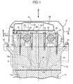
FIG. 1] FIG. 1 is a sectional view of an engine head part (a sectional view along line 1-1 inFIG. 2 ). (first embodiment) - [
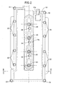
FIG. 2] FIG. 2 is a view fromarrow 2 inFIG. 1 . (first embodiment) - [
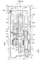
FIG. 3] FIG. 3 is a view from arrowed line 3-3 inFIG. 1 . (first embodiment) - [
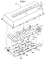
FIG. 4] FIG. 4 is an exploded perspective view of a head cover, a breather chamber main body, and a cover plate. (first embodiment) - [
FIG. 5] FIG. 5 is a sectional view along line 5-5 inFIG. 3 . (first embodiment) - [
FIG. 6] FIG. 6 is a sectional view along line 6-6 inFIG. 5 . (first embodiment) - [
FIG. 7] FIG. 7 is a sectional view along line 7-7 inFIG. 3 . (first embodiment) - [
FIG. 8] FIG. 8 is a sectional view along line 8-8 inFIG. 7 . (first embodiment) -
- 12
- Cylinder head
- 13
- Head cover
- 13a
- Recess
- 13c
- Coupling (blow-by gas outlet passage)
- 23
- Exhaust camshaft (camshaft)
- 25
- Exhaust cam (cam)
- 26
- Breather chamber
- 29
- Injector (combustion chamber interior inserted member)
- 30
- Blow-by gas inlet
- 31
- Blow-by gas outlet (blow-by gas outlet passage)
- L2
- Camshaft axis
- L3
- Cylinder axis
- P
- Plane containing camshaft: axis and parallel to cylinder axis
- R1
- First region
- R2
- Second region
- X
- Minimum distance between inner surface of head cover and outer surface of breather chamber
- Y
- Vertical length of blow-by gas inlet
- α
- Gap
- A mode for carrying out the present invention is explained below by reference to the attached drawings.
-
FIG. 1 to FIG. 8 show an embodiment of the present invention. - As shown in
FIG. 1 , in a direct fuel-injection engine, acylinder head 12 is joined to the upper end of acylinder block 11, and ahead cover 13 is joined to the upper end of thecylinder head 12. In the present specification, the vertical direction is defined such that thecylinder block 11 side is the lower side, and thehead cover 13 side is the upper side. - Formed in the
cylinder head 12 are acombustion chamber 14, and anintake port 15 and anexhaust port 16 communicating with thecombustion chamber 14, theintake port 15 being opened and closed by an intake valve 17 and theexhaust port 16 being opened and closed by anexhaust valve 18. Acamshaft holder 19 and acap 20 are superimposed on an upper face of thecylinder head 12 and secured by means of a plurality ofbolts 21, and anintake cam 24 and anexhaust cam 25 are provided respectively on anintake camshaft 22 and anexhaust camshaft 23 rotatably supported between thecamshaft holder 19 and thecap 20. Abreather chamber 26 is disposed between an upper face of thecap 20 and a lower face of thehead cover 13. Thebreather chamber 26 is made of a synthetic resin, and is formed by joining a breather chambermain body 27 on the upper side and acover plate 28 on the lower side. - The structure of the
breather chamber 26 is now explained by reference toFIG. 2 to FIG. 8 . - As shown in
FIG. 2 to FIG. 5 , arecess 13a that is recessed toward thecylinder head 12 side along a crankshaft axis L1 (seeFIG. 2 andFIG. 3 ) is formed in a central part of thehead cover 13, which has an open lower face, and four injectors 29 (seeFIG. 1 andFIG. 2 ) are disposed therein. Thebreather chamber 26 is substantially U-shaped overall; a blow-by gas inlet 30 is formed at one end, and a blow-bygas outlet 31 is formed at the other end. An annular space is formed in the interior of thehead cover 13 between an outer peripheral wall thereof and therecess 13a, and theU-shaped breather chamber 26 is disposed in this space. - As clearly shown in
FIG. 4 , the breather chambermain body 27 is a trough-shaped member having an open lower face, and the open part is blocked by the plate-shapedcover plate 28. That is, a joiningface 28a (section shown by light-colored shading) formed on the outer periphery of thecover plate 28 is joined by vibration welding to a joiningflange 27a formed along the outer periphery of the breather chambermain body 27, thereby forming thebreather chamber 26 in a tubular shape. A plurality (15 in the embodiment) of joiningflanges 28b (section shown by dark-colored shading) are projectingly provided on the outside of the joiningface 28a of thecover plate 28 in an adjacent state, and these joiningflames 28b are vibration welded to joiningfaces 13b (seeFIG. 5 ) on the inner surface of thehead cover 13. The joining faces 13b of the head cover are also shown by shading inFIG. 3 . - In a state in which the
breather chamber 26 is fixed to the interior of thehead cover 13 as above, a gap α (seeFIG. 1 ,FIG. 5 to FIG. 7 ) for forming an insulating space is formed between the outer surface of the breather chambermain body 27 and the inner surface of thehead cover 13. - As is clear from
FIG. 4 , the blow-by gas inlet 30 formed at one end of the breather chambermain body 27 opens sideways. The blow-bygas outlet 31 formed at the other end of the breather chambermain body 27 opens upward, and an annular joiningflange 27b is formed on the periphery thereof. Anoil drop hole 28c is formed in an intermediate section of thecover plate 28, and paired first andsecond baffle plates oil drop hole 28c and the blow-by gas inlet 30. - As is clear from
FIG. 3 ,FIG. 7 andFIG. 8 , afirst hanging wall 27c and asecond hanging wall 27d hang from an upper wall of the breather chambermain body 27; thefirst hanging wall 27c is formed in a comb shape separated into three, and thesecond hanging wall 27d has a large number of vertically extendingribs 27e formed on a face on thefirst hanging wall 27c side. Thefirst baffle plate 28d, thefirst hanging wall 27c, thesecond baffle plate 28e and thesecond hanging wall 27d are disposed in turn, and they form alabyrinth 32 for suppressing the flow of blow-by gas. Twolabyrinths 32 having the above arrangement are disposed in series. - As is clear from
FIG. 3 to FIG. 5 , the blow-by gas inlet 30 of thebreather chamber 26 opens sideways so as to face the inner surface of therecess 13a of thehead cover 13. Theexhaust camshaft 23, which is on the side close to the blow-by gas inlet 30 of thebreather chamber 26, is disposed therebeneath, and theexhaust camshaft 23 rotates clockwise inFIG. 5 . With a plane P passing through an axis L2 of theexhaust camshaft 23 and extending in the direction of a cylinder axis L3 as a reference, in a first region R1 on the left side thereof theexhaust cam 25 rotates from bottom to top, and in a second region R2 on the right side thereof theexhaust cam 25 rotates from top to bottom. The blow-by gas inlet 30 of thebreather chamber 26 opens in a direction away from the plane P in the second region R2. - As is clear from
FIG. 3 ,FIG. 5 , andFIG. 6 , the joiningflange 27b surrounding the blow-bygas outlet 31 of the breather chambermain body 27 is joined to a lower face of an upper wall of thehead cover 13 by vibration welding. Acoupling 13c is integrally formed on the breather chambermain body 27 in the vicinity of the blow-bygas outlet 31, and thiscoupling 13c is connected to an engine intake system via a breather hose, which is not illustrated. - The area of an opening of the blow-
by gas inlet 30 is set larger than the minimum passage cross-sectional area of the blow-by gas outlet passage, that is, the blow-bygas outlet 31 or thecoupling 13c. This is because, since the quantity of flow of a fluid is the product of the flow path cross-sectional area and the flow rate, the larger the flow path cross-sectional area, the lower the flow rate can be made. It is therefore possible by ensuring a large area for the opening of the blow-by gas inlet 30 to reduce the flow rate of blow-by gas in this section and prevent effectively oil from entering thebreather chamber 26 together with blow-by gas. - As is clear from
FIG. 1 , theoil drop hole 28c formed in thecover plate 28 of thebreather chamber 26 communicates with an oil pan, which is not illustrated, via anoil return passage 20a formed in thecap 20, anoil return passage 19a formed in thecamshaft holder 19, anoil return passage 12a formed in thecylinder head 12, and anoil return passage 11a formed in thecylinder block 11. In this way, forming theoil return passages breather chamber 26 by utilizing thecamshaft holder 19 and thecap 20 enables the lateral width of thehead cover 13 to be made small compared with a case in which they are formed on the exterior of thecamshaft holder 19 and thecap 20. - As is clear from
FIG. 5 , at the position where the blow-by gas inlet 30 is formed, a minimum distance X between the inner surface of therecess 13a of thehead cover 13 and the outer surface of thebreather chamber 26 is set smaller than a vertical length Y of the blow-by gas inlet 30. - As shown in
FIG. 2 ,FIG. 3 , andFIG. 5 , with regard to thehead cover 13 provided with thebreather chamber 26 having the above-mentioned structure, its outer peripheral part is fixed to the upper face of thecylinder head 12 via a plurality ofbolts 33, and itsrecess 13a is fixed to the upper face of thecylinder head 12 via a plurality ofbolts 34. - The operation of the embodiment of the present invention having the above-mentioned arrangement is now explained.
- Since the
breather chamber 26, to which blow-by gas is supplied, is provided with the gap α, which functions as an insulating space, between itself and thehead cover 13, it is possible to prevent blow-by gas within thebreather chamber 26 from freezing when the outside temperature decreases, thereby avoiding blockage of the blow-by gas passage. - Blow-by gas within the
head cover 13 flows into the interior of thebreather chamber 26 through the blow-by gas inlet 30 provided at one end of thebreather chamber 26, which has a substantially U-shaped form, and since the blow-by gas inlet 30 opens sideways so as to face the inner surface of a side wall of therecess 13a of thehead cover 13 rather than opening downward, even if the blow-by gas inlet 30 is formed large so as to reduce the flow rate of blow-by gas, it is possible to prevent effectively oil splashed up by a valve operating mechanism disposed beneath thebreather chamber 26 from entering the interior of thebreather chamber 26 through the blow-by gas inlet 30. Moreover, compared with a case in which the blow-by gas inlet 30 opens downward, the degree of freedom in layout of the blow-by gas inlet 30 can be enhanced. - In particular, in
FIG. 5 since the blow-by gas inlet 30 is disposed in the second region R2 in which theexhaust cam 25 provided on theexhaust camshaft 23 moves from top to bottom, that is, a region in which oil is not splashed up toward thebreather chamber 26, it is possible to further reliably prevent oil from entering thebreather chamber 26. - Furthermore, since in the vicinity of the blow-
by gas inlet 30 the minimum distance X between the inner surface of therecess 13a of thehead cover 13 and the outer surface of thebreather chamber 26 is set smaller than the vertical length Y of the blow-by gas inlet 30, it becomes difficult for oil to enter between the inner surface of therecess 13a of thehead cover 13 and the outer surface of thebreather chamber 26, and it is thereby also possible to prevent oil from entering thebreather chamber 26. - Although a trace amount of oil is still contained in blow-by gas that has flowed into the interior of the
breather chamber 26 through the blow-by gas inlet 30, since the blow-by gas passes through the twolabyrinths 32 and 32 (seeFIG. 3 ,FIG. 7 , andFIG. 8 ) while flowing through the interior of thebreather chamber 26, oil is reliably separated from the blow-by gas. The oil that has been separated from blow-by gas flows along a bottom wall of thebreather chamber 26 and is returned to the oil pan through theoil drop hole 28c (seeFIG. 1 andFIG. 3 ) via theoil return passages - Blow-by gas from which oil has been separated as above further flows toward the blow-by
gas outlet 31 through the interior of thebreather chamber 26, and oil that has not been separated by the twolabyrinths breather chamber 26 is a U shape that surrounds therecess 13a formed in a central part of thehead cover 13, the shape of thebreather chamber 26 is complex, thus promoting separation of oil. Blow-by gas from which oil has finally been separated returns to the engine intake system from the blow-bygas outlet 31 via thecoupling 13c and the breather hose, which is not illustrated. - An embodiment of the present invention is explained above, but the present invention may be modified in a variety of ways as long as the modifications do not depart from the spirit and scope thereof.
- For example, in the embodiment a direct fuel-injection engine is illustrated, but the present invention may be applied to both a gasoline engine and a diesel engine, and may also be applied to a port-injection type gasoline engine. In this case, instead of the
injectors 29 an ignition plug becomes the combustion chamber interior inserted member. - Furthermore, in the embodiment the blow-
by gas inlet 30 of thebreather chamber 26 opens sideways toward the inner surface of therecess 13a of thehead cover 13, but when the blow-by gas inlet 30 opens sideways toward the inner surface of an outer peripheral wall of thehead cover 13 or opens upward toward the inner surface of a ceiling wall of thehead cover 13, it is also possible to prevent effectively oil from entering the interior of thebreather chamber 26 through the blow-by gas inlet 30.
Claims (5)
- A breather device for an engine in which a breather chamber (26) is disposed in the interior of a head cover (13) joined to an engine cylinder head (12), and oil contained in blow-by gas returning to an intake system via the breather chamber (26) is separated, a predetermined gap (α) being formed between an outer surface of the breather chamber (26) and an inner surface of the head cover (13),
characterized in that a blow-by gas inlet (30) formed in a wall face of the breather chamber (26) opens at a position that faces an inner surface of the head cover (13). - The breather device for an engine according to Claim 1, wherein a recess (13a) in which a combustion chamber interior inserted member (29) is disposed is formed in an upper wall of the head cover (13), the breather chamber (26) is disposed at a position that avoids the recess (13a), and the blow-by gas inlet (30) opens at a position that faces an inner surface of the recess (13a).
- The breather device for an engine according to Claim 1 or Claim 2, wherein when an area around a camshaft (23) that is disposed beneath the breather chamber (26) and is the closest to the blow-by gas inlet (30) is divided by a plane (P) that contains an axis (L2) of the camshaft (23) and is parallel to a cylinder axis (L3) into a first region (R1) on the side where the tip of a cam (25) passes through from bottom to top and a second region (R2) on the side where the tip of the cam (25) passes through from top to bottom, the blow-by gas inlet (30) opens in the second region (R2).
- The breather device for an engine according to any one of Claim 1 to Claim 3, wherein a minimum distance (X) between the inner surface of the head cover (13) and the outer surface of the breather chamber (26) is set smaller than a vertical length (Y) of the blow-by gas inlet (30) at a position in which the blow-by gas inlet (30) is formed.
- The breather device for an engine according to any one of Claim 1 to Claim 4, wherein the breather chamber (26) communicates with a blow-by gas outlet passage (31, 13c), and the area of an opening of the blow-by gas inlet (30) is formed larger than the area of the minimum passage cross-section of the blow-by gas outlet passage (31, 13c).
Applications Claiming Priority (2)
| Application Number | Priority Date | Filing Date | Title |
|---|---|---|---|
| JP2007179244A JP2009013941A (en) | 2007-07-09 | 2007-07-09 | Engine breather equipment |
| PCT/JP2008/062336 WO2009008427A1 (en) | 2007-07-09 | 2008-07-08 | Breather device for engine |
Publications (2)
| Publication Number | Publication Date |
|---|---|
| EP2163738A1 true EP2163738A1 (en) | 2010-03-17 |
| EP2163738A4 EP2163738A4 (en) | 2010-08-04 |
Family
ID=40228597
Family Applications (1)
| Application Number | Title | Priority Date | Filing Date |
|---|---|---|---|
| EP08790973A Withdrawn EP2163738A4 (en) | 2007-07-09 | 2008-07-08 | Breather device for engine |
Country Status (4)
| Country | Link |
|---|---|
| EP (1) | EP2163738A4 (en) |
| JP (1) | JP2009013941A (en) |
| CN (1) | CN101680320A (en) |
| WO (1) | WO2009008427A1 (en) |
Cited By (3)
| Publication number | Priority date | Publication date | Assignee | Title |
|---|---|---|---|---|
| EP2336509A1 (en) * | 2009-12-08 | 2011-06-22 | MAN Truck & Bus AG | Cylinder head cower for combustion engines |
| FR3018555A1 (en) * | 2014-03-11 | 2015-09-18 | Peugeot Citroen Automobiles Sa | MOTOR VEHICLE COMBUSTION ENGINE WITH LOW DIMENSIONS |
| US10914211B2 (en) | 2018-03-09 | 2021-02-09 | Honda Motor Co., Ltd. | Internal combustion engine with gas-liquid separator for blowby gas |
Families Citing this family (10)
| Publication number | Priority date | Publication date | Assignee | Title |
|---|---|---|---|---|
| JP5495402B2 (en) * | 2012-11-22 | 2014-05-21 | アイシン精機株式会社 | Oil separator |
| CN104520546B (en) * | 2012-07-04 | 2017-09-01 | 爱信精机株式会社 | oil separator |
| JP2014013012A (en) * | 2012-07-04 | 2014-01-23 | Aisin Seiki Co Ltd | Oil separator |
| JP2014105582A (en) * | 2012-11-22 | 2014-06-09 | Aisin Seiki Co Ltd | Oil separator |
| JP6442387B2 (en) * | 2015-09-30 | 2018-12-19 | 株式会社クボタ | Engine breather equipment |
| JP6442388B2 (en) * | 2015-09-30 | 2018-12-19 | 株式会社クボタ | Engine breather equipment |
| JP6450295B2 (en) * | 2015-09-30 | 2019-01-09 | 株式会社クボタ | Engine breather equipment |
| US10683784B2 (en) | 2018-11-20 | 2020-06-16 | Honda Motor Co., Ltd. | Oil mist separator |
| JP7221702B2 (en) * | 2019-01-11 | 2023-02-14 | 株式会社クボタ | Blow-by gas reflux device |
| DE102019000498A1 (en) * | 2019-01-23 | 2020-07-23 | Deutz Aktiengesellschaft | Cylinder head |
Family Cites Families (9)
| Publication number | Priority date | Publication date | Assignee | Title |
|---|---|---|---|---|
| JPS59167906U (en) * | 1983-04-26 | 1984-11-10 | 愛知機械工業株式会社 | Oil separation device for internal combustion engine rocker cover |
| JPH0441210Y2 (en) * | 1985-06-12 | 1992-09-28 | ||
| JPH0625623Y2 (en) * | 1986-05-30 | 1994-07-06 | いすゞ自動車株式会社 | Cylinder head cover |
| JPH064015Y2 (en) * | 1986-07-07 | 1994-02-02 | いすゞ自動車株式会社 | Cylinder head cover structure |
| JP3137397B2 (en) * | 1991-12-24 | 2001-02-19 | マツダ株式会社 | Oil separator for blow-by gas reduction unit |
| JPH06288219A (en) * | 1993-03-31 | 1994-10-11 | Suzuki Motor Corp | Breather device |
| US6443136B1 (en) * | 2000-10-25 | 2002-09-03 | Honda Giken Kogyo Kabushiki Kaisha | Breather apparatus for an internal combustion engine |
| JP2006022700A (en) * | 2004-07-07 | 2006-01-26 | Toyota Motor Corp | Blow-by gas reduction device |
| JP2007285261A (en) * | 2006-04-19 | 2007-11-01 | Toyota Industries Corp | Blow-by treatment device for internal combustion engine |
-
2007
- 2007-07-09 JP JP2007179244A patent/JP2009013941A/en active Pending
-
2008
- 2008-07-08 CN CN200880020489A patent/CN101680320A/en active Pending
- 2008-07-08 WO PCT/JP2008/062336 patent/WO2009008427A1/en not_active Ceased
- 2008-07-08 EP EP08790973A patent/EP2163738A4/en not_active Withdrawn
Cited By (3)
| Publication number | Priority date | Publication date | Assignee | Title |
|---|---|---|---|---|
| EP2336509A1 (en) * | 2009-12-08 | 2011-06-22 | MAN Truck & Bus AG | Cylinder head cower for combustion engines |
| FR3018555A1 (en) * | 2014-03-11 | 2015-09-18 | Peugeot Citroen Automobiles Sa | MOTOR VEHICLE COMBUSTION ENGINE WITH LOW DIMENSIONS |
| US10914211B2 (en) | 2018-03-09 | 2021-02-09 | Honda Motor Co., Ltd. | Internal combustion engine with gas-liquid separator for blowby gas |
Also Published As
| Publication number | Publication date |
|---|---|
| WO2009008427A1 (en) | 2009-01-15 |
| CN101680320A (en) | 2010-03-24 |
| JP2009013941A (en) | 2009-01-22 |
| EP2163738A4 (en) | 2010-08-04 |
Similar Documents
| Publication | Publication Date | Title |
|---|---|---|
| EP2163738A1 (en) | Breather device for engine | |
| US7556029B2 (en) | Oil separator for an engine | |
| CN109252914B (en) | Cylinder head cover structure of engine | |
| US20040244783A1 (en) | Crankcase emission control device | |
| US6530367B2 (en) | Engine air-oil separator | |
| EP2177726A1 (en) | Vapor-liquid separating structure | |
| JP2010090802A (en) | Blow-by gas recirculation device for internal combustion engine | |
| JP4225327B2 (en) | Oil return structure for internal combustion engine | |
| JP2012241551A (en) | Oil separator of internal combustion engine | |
| JP2009203977A (en) | Breather device for internal combustion engine | |
| JP2003293725A (en) | PCV device for internal combustion engine | |
| JP4730279B2 (en) | Engine intake system | |
| CN101413414B (en) | Blow-by gas processing device for internal combustion engine | |
| JP2013151905A (en) | Oil separator of blowby gas processing device | |
| JP4506570B2 (en) | Internal combustion engine and method of refueling internal combustion engine | |
| JP2008025371A (en) | Lubricating oil supply structure | |
| CN111379609A (en) | Engine | |
| JP3791737B2 (en) | Engine cylinder head cover | |
| JP2003120245A (en) | Intake device for internal combustion engine | |
| JP5927935B2 (en) | Blow-by gas reduction device | |
| JP4075772B2 (en) | Engine oil separator | |
| CN117145647A (en) | Cylinder head cover and engine | |
| JP6551446B2 (en) | Engine oil separator structure | |
| JP4582003B2 (en) | Blowby gas recirculation structure of internal combustion engine | |
| JP2006283594A (en) | Engine breather equipment |
Legal Events
| Date | Code | Title | Description |
|---|---|---|---|
| PUAI | Public reference made under article 153(3) epc to a published international application that has entered the european phase |
Free format text: ORIGINAL CODE: 0009012 |
|
| 17P | Request for examination filed |
Effective date: 20091217 |
|
| AK | Designated contracting states |
Kind code of ref document: A1 Designated state(s): AT BE BG CH CY CZ DE DK EE ES FI FR GB GR HR HU IE IS IT LI LT LU LV MC MT NL NO PL PT RO SE SI SK TR |
|
| AX | Request for extension of the european patent |
Extension state: AL BA MK RS |
|
| A4 | Supplementary search report drawn up and despatched |
Effective date: 20100702 |
|
| RIC1 | Information provided on ipc code assigned before grant |
Ipc: F01M 13/02 20060101ALI20100628BHEP Ipc: F01M 13/04 20060101AFI20100628BHEP |
|
| DAX | Request for extension of the european patent (deleted) | ||
| 17Q | First examination report despatched |
Effective date: 20110405 |
|
| STAA | Information on the status of an ep patent application or granted ep patent |
Free format text: STATUS: THE APPLICATION IS DEEMED TO BE WITHDRAWN |
|
| 18D | Application deemed to be withdrawn |
Effective date: 20110817 |