EP2163475A2 - Propellerenteisungssystem - Google Patents
Propellerenteisungssystem Download PDFInfo
- Publication number
- EP2163475A2 EP2163475A2 EP09252202A EP09252202A EP2163475A2 EP 2163475 A2 EP2163475 A2 EP 2163475A2 EP 09252202 A EP09252202 A EP 09252202A EP 09252202 A EP09252202 A EP 09252202A EP 2163475 A2 EP2163475 A2 EP 2163475A2
- Authority
- EP
- European Patent Office
- Prior art keywords
- heater
- time
- blades
- ambient temperature
- maximum
- Prior art date
- Legal status (The legal status is an assumption and is not a legal conclusion. Google has not performed a legal analysis and makes no representation as to the accuracy of the status listed.)
- Granted
Links
Images


Classifications
-
- B—PERFORMING OPERATIONS; TRANSPORTING
- B64—AIRCRAFT; AVIATION; COSMONAUTICS
- B64D—EQUIPMENT FOR FITTING IN OR TO AIRCRAFT; FLIGHT SUITS; PARACHUTES; ARRANGEMENT OR MOUNTING OF POWER PLANTS OR PROPULSION TRANSMISSIONS IN AIRCRAFT
- B64D15/00—De-icing or preventing icing on exterior surfaces of aircraft
- B64D15/12—De-icing or preventing icing on exterior surfaces of aircraft by electric heating
Definitions
- aircraft propeller ice protection is typically performed by deicing, where blade heaters are cycled on and off to shed accreted ice, as opposed to antiicing where heaters are left on continuously to avoid any ice accretion.
- Current propeller deicing systems employ discrete heater timing cycles (heater on/heater off schedules) based on ambient air temperature. These discrete timing cycles make it difficult to design a system which operates optimally at all flight conditions. Therefore, a need exists for improved systems and methods of deicing propeller blades that dynamically adjust for varying flight conditions allowing the deicing system to remove ice from the blades more effectively over the full range of aircraft flight conditions.
- Embodiments of the present invention include systems and methods of deicing aircraft propellers in which a deicing heater timing cycle, i.e. heater on/heater off schedule, is calculated as a function of ambient temperature and the airspeed of the aircraft.
- a deicing heater timing cycle i.e. heater on/heater off schedule
- FIG. 1 is a schematic of propeller deicing system 10 including propeller 12, temperature sensor 14, airspeed sensor 16, and controller 18.
- Propeller 12 has four blades 20, 22, 24, 26, but embodiments of the present invention are not limited to any particular number of propeller blades.
- Each of propeller blades 20-26 includes one heater element 28. Heater elements 28 are supported on blades 20-26 in a conventional manner.
- Blades 20-26 include two sets of two opposing blades 20, 24 and 22, 26. In some embodiments of the present invention, heaters 28 associated with each set of two or more opposing blades (20, 24 or 22, 26) may be controlled simultaneously to prevent imbalanced conditions where ice accretes on one blade that is opposite from another blade.
- Controller 18 receives temperature and airspeed readings from temperature sensor 14 and airspeed sensor 16, and controls the operation of blade heaters 28 as function of the temperature and airspeed inputs. Controller 18 is electrically connected to temperature sensor 14 and airspeed sensor 16 to receive ambient temperature information and aircraft airspeed information respectively.
- Temperature sensor 14 may be any conventional sensor capable of detecting ambient air temperature. Temperature sensor 14 may be connected to the aircraft on which propeller 12 is mounted at any convenient location to measure the necessary ambient temperature information. Temperature sensor 14 may be, for example, a standard platinum sense resistor. Alternatively, temperature sensor 14 may be a non-linear thermistor or a silicon resistor. However, in general, any temperature sensor appropriate for the intended application may be selected.
- airspeed sensor 16 may be any sensor capable of detecting the airspeed of the aircraft to which propeller 12 is connected. The system may include additional sensors to detect quantities such as aircraft altitude and propeller rpm in order to further specify the flight condition.
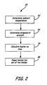
- FIG. 2 is a flow chart of method 30 of deicing propeller blades on an aircraft, which initially involves determining an ambient temperature (step 32) and airspeed of the aircraft (step 34).
- the ambient temperature and aircraft airspeed may be determined, as described above, using conventional temperature and speed sensors appropriately mounted on the aircraft for taking measurements.
- method 30 In addition to determining an ambient temperature (step 32) and airspeed of the aircraft (step 34), method 30 also includes calculating heater on and off times as a function of the ambient temperature and the airspeed (step 36).
- the heater timing cycle for deicing systems according to the present invention generally speaking, includes a heater on time and a heater off time the sum of which defines one complete cycle.
- propeller blades are typically deiced as opposing sets of blades (i.e. two sets of two blades on a four blade propeller, three sets of two blades or two sets of three blades on a six blade propeller, four sets of two blades or two sets of four blades on an eight blade propeller, etc.). These sets of blades are heated in sequence to keep overall power usage at an acceptable level.
- an eight blade propeller has four opposing sets of two blades. Each of the four sets of two blades is heated in sequence.
- the heater off time must be at least three times the heater on time. This means that the maximum duty cycle is one in four. Assuming that this maximum duty cycle is optimum, this relationship between the on and off time, and the fact that the desired peak surface temperature is near 32° Fahrenheit (0° Celsius), can be used to define optimum timing cycles.
- a schedule of optimum heater on and off times may be developed by calculating optimum heater cycle times at an array of ambient temperature and airspeed. This may include calculating a plurality of blade surface temperatures over a period of time with the heater on at a first time and the heater off when the surface temperature of the blade reaches approximately 32° Fahrenheit (0° Celsius), and determining the optimum heater on time from the calculated blade surface temperatures. The analysis can be performed for as many ambient temperature / velocity (and optionally rpm / altitude) combinations deemed necessary. For a given ambient temperature and airspeed, conventional heat transfer analysis may be used to calculate the time required to heat the surface of a propeller blade to 32° Fahrenheit (0° Celsius).
- FIG. 3 is an example graph of blade surface temperature as a function of time with the heater on at a first time and the heater off when the surface temperature of the blade reaches approximately 32° Fahrenheit (0° Celsius).
- the overshoot in temperature above 32° Fahrenheit (0° Celsius) is due in part to the fact that the resolution of the calculations in time in this example do not allow for the application of heat to stop at exactly 32° Fahrenheit (0° Celsius).
- blade surface temperature and time for a given heater cycle can then be used to determine the heater on time by calculating a minimum heating cycle blade surface temperature from which the blade will heat to approximately 32° Fahrenheit (0° Celsius) in an optimum heater on time and to which the blade will cool from approximately 32° Fahrenheit (0° Celsius) in an optimum heater off time that is equal to the optimum heater on time multiplied by the number of sets of blades in the plurality of blades minus one.
- the curve of FIG. 3 can be used to determine the one in four timing cycle for which the heater will cycle with a peak temperature of 32° Fahrenheit (0° Celsius). This is done by determining the minimum heating cycle temperature for which the time it takes the blade surface to heat up to 32° Fahrenheit (0° Celsius) is one third of the time it takes to cool down from 32° Fahrenheit (0° Celsius) to the same minimum heating cycle temperature.
- the minimum cycle temperature is T cycle min and the heater on time is t on , which is one third of the heater off time t off .
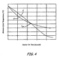
- the heater on time portion can be plotted as minimum heating cycle temperature vs. the heater on time by reversing the time scale with zero time at the point where the temperature reaches 32° Fahrenheit (0° Celsius).
- the heater off time portion can be plotted on the same scale by shifting the 32° Fahrenheit (0° Celsius) point to zero time and dividing the original time scale by the number of sets of blades in the plurality of blades minus one.
- Curve A represents the heater on time
- curve B represents the heater off time.
- the two curves A, B cross at the optimum heater on time.
- the analysis set out with reference to FIGS. 3 and 4 may be performed at a range of ambient temperature and aircraft airspeed combinations that cover the operating range of the aircraft.
- the resulting heater timing cycles at various combinations of ambient temperature and aircraft airspeed will have a peak blade surface temperature near 32° Fahrenheit (0° Celsius).
- this analysis may result in undesirably long heater cycle times.
- the maximum timing cycle may need to be limited.
- a minimum heater on time, t min on can be chosen. For heater on times less than t min on or when no heater on time can be defined, a delay time can be added to the heater off time (shifting the heater off time curve in FIG. 4 to the left) such that t min on results in a peak temperature of 32° Fahrenheit (0° Celsius). In some cases this will result in long heater off times. Therefore, similar to the limitation which may need to be applied on the minimum heater on time, the heater off time calculated in this situation may also need to be limited by, for example, setting a maximum heater off time, t max off .
- FIG. 5 An example of the resulting heater on and off times is plotted as a function of aircraft airspeed and ambient temperature in FIG. 5 .
- Each of the curves v 1 - v 7 shown in FIG. 5 represents a heater timing cycle, i.e. heater on and off times, as a function of ambient temperature at one of seven different aircraft airspeeds.
- FIG. 5 is meant to be illustrative only and it will be understood that the heater timing cycle curves may be calculated for any aircraft airspeed.
- method 30 In addition to calculating a heater on time as a function of the ambient temperature and aircraft airspeed (step 36), method 30 also includes powering a heater for a set of opposing blades in the plurality of blades for the heater on time (step 38). The heater for the remaining sets of opposing blades may then be powered in sequence to complete one heating cycle. After completing one heating cycle, deicing systems according to the present invention may repeat another heating cycle with the same heater on and off times, or may take new ambient temperature and aircraft airspeed measurements and then repeat another heating cycle with heater on and off times calculated based on the new temperature and speed conditions.
- the maximum ambient temperature where the heaters will be turned on can be defined as a function of the aircraft airspeed.
- the temperature limit corresponding to T max on can be defined by determining the temperature above which the blade surface temperature is near the freezing point due to dynamic heating alone with no additional heat from the deicing system. This may mean that for certain conditions, the propeller deicing system will be activated but the blade heaters will not be turned on.
- FIG. 6 is a flow chart which outlines a process of operating the deicing heaters with timing cycles defined as outlined above for the example with four sets of heaters.
- either the pilot or the aircraft ice detection system signals the propeller deicing system that ice accretion is occurring (step 40) and an ambient temperature, T amb , and airspeed of the aircraft, v, are determined (step 42).
- the ambient temperature and aircraft airspeed may be determined, as described above, using conventional temperature and speed sensors appropriately mounted on the aircraft for taking measurements.
- the ambient temperature and aircraft airspeed are transmitted to the deicing system.
- the propeller deicing system may then determine in a conventional manner, based on airspeed and ambient temperature, whether or not to activate the blade heaters by determining whether or not the T amb is less than T max on by first calculating T max on (step 44) and then comparing T amb to T max on (step 46). If the ambient temperature (T amb ) is greater than T max on the blade heaters are not powered. However, the propeller deicing system continues to monitor ambient temperature and airspeed, calculate T max on, and compare to T amb for as long as the aircraft or pilot is signaling that accretion is occurring.
- the heater on time (t on ) is calculated (step 48) based on the results of the analysis outlined above. If the calculated heater on time is greater than a defined maximum on time (step 50), t on is set to the maximum on time, t max on , and the heater off time (t off ) is set to (in the example that includes eight propeller blades set out above) 3 times the maximum heater on time (step 52). If the calculated heater on time is greater than or equal to a defined minimum on time (step 54) and less than or equal to the maximum on time, t on is not changed, and t off is set to 3 times t on (step 56).
- step 54 If the calculated heater on time is less than the minimum on time (step 54), t on is set to the minimum on time, t min on , and the appropriate t off including a delay time may be calculated (step 58). If the resulting calculated heater off time is greater than a maximum heater off time (step 60), t off is set to the maximum off time, t max off (step 62). The heater off time, t off , can be greater than t max off when the original t on is not less than t min on .
- each of the heater sets associated with each of the sets of opposing propeller blades is turned on in sequence (step 64).
- the propeller system will check to see that the aircraft system or pilot is still requesting propeller deicing (step 66). If so, the calculation of the appropriate timing cycle and operation of heaters is repeated. If not, the deicing system is turned off (step 68).
- Embodiments of the present invention improve on prior propeller deicing systems and methods by increasing the effectiveness of ice removal by dynamically adjusting the heating timing cycle for a variety of flight conditions.
- Methods and systems according to the present invention calculate deicing heater timing cycles, i.e. heater on/heater off schedules, as a function of both ambient temperature and the airspeed of the aircraft. Including the aircraft airspeed better optimizes the heater timing cycles for particular flight conditions and thereby accounts for factors like dynamic heating at higher airspeeds that replace or augment the need to power deicing system.
- the present invention may be expanded to include the influence of other flight condition variables such as altitude and propeller rpm. Increasing the effectiveness of the deicing system generally reduces the amount of ice accreted on the propeller blades between ice shedding, resulting in improved aircraft performance in icing conditions and decreased energy of shed ice impacts on the aircraft structure.
Landscapes
- Engineering & Computer Science (AREA)
- Aviation & Aerospace Engineering (AREA)
- Control Of Resistance Heating (AREA)
- Air-Conditioning For Vehicles (AREA)
Applications Claiming Priority (2)
| Application Number | Priority Date | Filing Date | Title |
|---|---|---|---|
| US19213808P | 2008-09-16 | 2008-09-16 | |
| US12/396,896 US9656757B2 (en) | 2008-09-16 | 2009-03-03 | Propeller deicing system |
Publications (3)
| Publication Number | Publication Date |
|---|---|
| EP2163475A2 true EP2163475A2 (de) | 2010-03-17 |
| EP2163475A3 EP2163475A3 (de) | 2012-06-27 |
| EP2163475B1 EP2163475B1 (de) | 2017-03-15 |
Family
ID=41338682
Family Applications (1)
| Application Number | Title | Priority Date | Filing Date |
|---|---|---|---|
| EP09252202.8A Active EP2163475B1 (de) | 2008-09-16 | 2009-09-16 | Propellerenteisungssystem |
Country Status (2)
| Country | Link |
|---|---|
| US (1) | US9656757B2 (de) |
| EP (1) | EP2163475B1 (de) |
Cited By (2)
| Publication number | Priority date | Publication date | Assignee | Title |
|---|---|---|---|---|
| US9499273B2 (en) | 2013-02-01 | 2016-11-22 | Rolls-Royce Plc | De-icing apparatus and a method of using the same |
| RU2700151C2 (ru) * | 2014-11-11 | 2019-09-12 | Зе Боинг Компани | Системы для комбинированных нагревателей зон для летательного аппарата с несущим винтом и способы их эксплуатации |
Families Citing this family (12)
| Publication number | Priority date | Publication date | Assignee | Title |
|---|---|---|---|---|
| EP2032916A2 (de) * | 2006-05-22 | 2009-03-11 | The Trustees of Dartmouth College | Enteisung komplexer formen durch elektrothermale impulse |
| US20100326041A1 (en) * | 2009-06-30 | 2010-12-30 | Wayne Garcia Edmondson | Heated guide vane |
| US20100329836A1 (en) * | 2009-06-30 | 2010-12-30 | Wayne Garcia Edmondson | Method of operating a heated guide vane assembly |
| US9683489B2 (en) | 2013-08-09 | 2017-06-20 | Honeywell International Inc. | System and method for preventing ice crystal accretion in gas turbine engines |
| US9638044B2 (en) | 2014-03-11 | 2017-05-02 | Hamilton Sundstrand Corporation | Resistive-inductive propeller blade de-icing system including contactless power supply |
| US10543926B2 (en) * | 2015-12-21 | 2020-01-28 | Sikorsky Aircraft Corporation | Ice protection systems |
| DE102016111902B4 (de) * | 2016-06-29 | 2024-08-01 | Deutsches Zentrum für Luft- und Raumfahrt e.V. | Verfahren und Assistenzsystem zur Detektion einer Flugleistungsdegradierung |
| US10710732B2 (en) * | 2017-09-15 | 2020-07-14 | Bell Helicopter Textron Inc. | Rotary aircraft ice protection system |
| US10822999B2 (en) * | 2018-07-24 | 2020-11-03 | Raytheon Technologies Corporation | Systems and methods for fan blade de-icing |
| EP3650349B1 (de) | 2018-11-07 | 2022-03-02 | Ratier-Figeac SAS | Enteisungssystem und -verfahren |
| CA3110197A1 (en) | 2020-03-31 | 2021-09-30 | Hamilton Sundstrand Corporation | Multi-element propeller blade deicer scheme for balanced three-phase electrical loads |
| US11897619B2 (en) * | 2021-11-22 | 2024-02-13 | Rosemount Aerospace Inc. | Heating prognostics system for ice protection system |
Family Cites Families (41)
| Publication number | Priority date | Publication date | Assignee | Title |
|---|---|---|---|---|
| US684459A (en) * | 1898-01-29 | 1901-10-15 | Bay State Electric Heat & Light Company | Electric heater. |
| US2437318A (en) * | 1944-01-31 | 1948-03-09 | Honeywell Regulator Co | Aircraft heating control system |
| US2556736A (en) * | 1945-06-22 | 1951-06-12 | Curtiss Wright Corp | Deicing system for aircraft |
| US2638295A (en) * | 1947-04-19 | 1953-05-12 | Curtiss Wright Corp | Propeller deicing mechanism |
| US2690890A (en) * | 1949-02-25 | 1954-10-05 | Wind Turbine Company | Deicing system for airfoil structures |
| US2540472A (en) * | 1949-05-02 | 1951-02-06 | A V Roe Canada Ltd | Electrically heated blade and process of manufacture |
| US3657514A (en) * | 1970-06-03 | 1972-04-18 | Goodrich Co B F | Electrical deicer for aircraft propeller |
| US4292502A (en) * | 1979-02-05 | 1981-09-29 | The B.F. Goodrich Company | Helicopter deicer control system |
| US4424947A (en) * | 1981-07-02 | 1984-01-10 | The B. F. Goodrich Company | Helicopter deicer system power transfer assembly |
| DE3815906A1 (de) * | 1988-05-10 | 1989-11-23 | Mtu Muenchen Gmbh | Luftschraubenblatt aus faserverstaerktem kunststoff |
| US5074497A (en) * | 1989-08-28 | 1991-12-24 | The B. F. Goodrich Company | Deicer for aircraft |
| GB2243412B (en) * | 1990-03-30 | 1994-11-23 | United Technologies Corp | Aircraft engine propulsor blade deicing |
| US5174717A (en) * | 1991-06-10 | 1992-12-29 | Safeway Products Inc. | Cable harness and mounting hardware for propeller deicer |
| US5796612A (en) * | 1992-11-18 | 1998-08-18 | Aers/Midwest, Inc. | Method for flight parameter monitoring and control |
| US5558495A (en) * | 1993-12-02 | 1996-09-24 | Sundstrand Corporation | Electromagnetic heating devices, particularly for ram air turbines |
| US5709532A (en) * | 1994-12-29 | 1998-01-20 | The B.F. Goodrich Company | Propeller ice protection system and method providing reduced sliding contact maintenance |
| US5691691A (en) * | 1997-01-06 | 1997-11-25 | Motorola, Inc. | Power-line communication system using pulse transmission on the AC line |
| US5997250A (en) * | 1997-01-09 | 1999-12-07 | Catercopters, Llc | Method and apparatus for controlling pitch of an aircraft propeller |
| US6070418A (en) * | 1997-12-23 | 2000-06-06 | Alliedsignal Inc. | Single package cascaded turbine environmental control system |
| US6304194B1 (en) * | 1998-12-11 | 2001-10-16 | Continuum Dynamics, Inc. | Aircraft icing detection system |
| DK173607B1 (da) * | 1999-06-21 | 2001-04-30 | Lm Glasfiber As | Vindmøllevinge med system til afisning af lynbeskyttelse |
| US7131812B2 (en) * | 2002-01-18 | 2006-11-07 | Manfred Karl Brueckner | Sky turbine that is mounted on a city |
| JP2003222026A (ja) * | 2002-01-30 | 2003-08-08 | Hitachi Ltd | タービン翼の製作方法およびタービン翼 |
| US6851929B2 (en) * | 2002-03-19 | 2005-02-08 | Hamilton Sundstrand | System for powering and controlling a device associated with a rotating component on aircraft |
| US6753513B2 (en) * | 2002-03-19 | 2004-06-22 | Hamilton Sundstrand | Propeller de-icing system |
| DK1658515T3 (da) * | 2003-08-25 | 2010-03-01 | Univ Corp Atmospheric Res | Afisningsinformationssystem |
| US6890152B1 (en) * | 2003-10-03 | 2005-05-10 | General Electric Company | Deicing device for wind turbine blades |
| US7043146B2 (en) * | 2003-12-15 | 2006-05-09 | Solomon Semaza | All season heat fan with electric heating elements powered by rotating rings and ball bearings |
| ATE378603T1 (de) * | 2004-03-26 | 2007-11-15 | Univ Danmarks Tekniske | Verfahren und vorrichtung zur ermittlung der von einer windturbine erfahrenen windgeschwindigkeit und -richtung |
| US7086834B2 (en) * | 2004-06-10 | 2006-08-08 | General Electric Company | Methods and apparatus for rotor blade ice detection |
| US7217091B2 (en) * | 2004-07-20 | 2007-05-15 | General Electric Company | Methods and apparatus for deicing airfoils or rotor blades |
| IL165233A (en) * | 2004-11-16 | 2013-06-27 | Israel Hirshberg | Energy conversion facility |
| CN101068715B (zh) | 2005-02-24 | 2012-01-25 | 贝尔直升机泰克斯特龙公司 | 用于旋翼飞行器的冰管理系统 |
| US7348683B2 (en) * | 2005-11-17 | 2008-03-25 | General Electric Company | Rotor for a wind energy turbine |
| US7355302B2 (en) * | 2005-11-23 | 2008-04-08 | Ice Corporation | System and method for providing power and control through a rotating interface |
| US7708227B2 (en) * | 2006-01-06 | 2010-05-04 | Cox & Company, Inc. | Energy-efficient electro-thermal ice-protection system |
| US20070187381A1 (en) * | 2006-02-16 | 2007-08-16 | United Technologies Corporation | Heater assembly for deicing and/or anti-icing a component |
| US7313963B2 (en) * | 2006-02-28 | 2008-01-01 | General Electric Company | Isothermal de-iced sensor |
| WO2007107732A1 (en) | 2006-03-17 | 2007-09-27 | Ultra Electronics Limited | Ice protection system |
| US7502717B2 (en) * | 2006-04-18 | 2009-03-10 | Honeywell International Inc. | Method for predicting air cycle machine turbine ice formation and shedding and journal bearing wear |
| US7896616B2 (en) * | 2007-01-29 | 2011-03-01 | General Electric Company | Integrated leading edge for wind turbine blade |
-
2009
- 2009-03-03 US US12/396,896 patent/US9656757B2/en active Active
- 2009-09-16 EP EP09252202.8A patent/EP2163475B1/de active Active
Cited By (3)
| Publication number | Priority date | Publication date | Assignee | Title |
|---|---|---|---|---|
| US9499273B2 (en) | 2013-02-01 | 2016-11-22 | Rolls-Royce Plc | De-icing apparatus and a method of using the same |
| RU2700151C2 (ru) * | 2014-11-11 | 2019-09-12 | Зе Боинг Компани | Системы для комбинированных нагревателей зон для летательного аппарата с несущим винтом и способы их эксплуатации |
| RU2700151C9 (ru) * | 2014-11-11 | 2020-03-26 | Зе Боинг Компани | Системы для комбинированных нагревателей зон для летательного аппарата с несущим винтом и способы их эксплуатации |
Also Published As
| Publication number | Publication date |
|---|---|
| EP2163475B1 (de) | 2017-03-15 |
| US20100065541A1 (en) | 2010-03-18 |
| EP2163475A3 (de) | 2012-06-27 |
| US9656757B2 (en) | 2017-05-23 |
Similar Documents
| Publication | Publication Date | Title |
|---|---|---|
| EP2163475B1 (de) | Propellerenteisungssystem | |
| EP2428447B1 (de) | Eiserkennungssystem und -verfahren | |
| EP2943404B1 (de) | Vorrichtung und verfahren zur erkennung von wasser oder eis | |
| CN113316685B (zh) | 与风力涡轮机叶片防冰系统有关的改进 | |
| US10634118B2 (en) | Method for operating a wind turbine having a rotor blade heating device | |
| US6370450B1 (en) | Integrated total temperature probe system | |
| EP2657133A2 (de) | Eisschutzsystem für Flugzeug mit optimierter Funktion basierend auf Eiserfassungseingabe | |
| US8746622B2 (en) | Aircraft de-icing system and method | |
| US11242152B2 (en) | Method and apparatus for detecting ice accretion | |
| EP3677509B1 (de) | Vorwärmlogik für flugzeugeisschutzsteuerungssystem | |
| EP4065470B1 (de) | Vorrichtung und verfahren zur erkennung von wasser oder eis | |
| EP2692640A2 (de) | Eisschutzsystem | |
| EP3645879B1 (de) | Verbessertes elektrothermisches heizsystem für windturbinenschaufeln | |
| CN120712221A (zh) | 用于根据积冰速率控制飞行器中的防结冰装置的方法以及对应的系统 | |
| US11358727B2 (en) | Method and apparatus for predicting conditions favorable for icing | |
| US11390387B2 (en) | De-icing system and method | |
| JPS60261799A (ja) | プロペラの除氷システム |
Legal Events
| Date | Code | Title | Description |
|---|---|---|---|
| PUAI | Public reference made under article 153(3) epc to a published international application that has entered the european phase |
Free format text: ORIGINAL CODE: 0009012 |
|
| AK | Designated contracting states |
Kind code of ref document: A2 Designated state(s): AT BE BG CH CY CZ DE DK EE ES FI FR GB GR HR HU IE IS IT LI LT LU LV MC MK MT NL NO PL PT RO SE SI SK SM TR |
|
| AX | Request for extension of the european patent |
Extension state: AL BA RS |
|
| PUAL | Search report despatched |
Free format text: ORIGINAL CODE: 0009013 |
|
| AK | Designated contracting states |
Kind code of ref document: A3 Designated state(s): AT BE BG CH CY CZ DE DK EE ES FI FR GB GR HR HU IE IS IT LI LT LU LV MC MK MT NL NO PL PT RO SE SI SK SM TR |
|
| AX | Request for extension of the european patent |
Extension state: AL BA RS |
|
| RIC1 | Information provided on ipc code assigned before grant |
Ipc: B64D 15/12 20060101AFI20120523BHEP |
|
| 17P | Request for examination filed |
Effective date: 20130102 |
|
| GRAP | Despatch of communication of intention to grant a patent |
Free format text: ORIGINAL CODE: EPIDOSNIGR1 |
|
| INTG | Intention to grant announced |
Effective date: 20161130 |
|
| GRAS | Grant fee paid |
Free format text: ORIGINAL CODE: EPIDOSNIGR3 |
|
| GRAA | (expected) grant |
Free format text: ORIGINAL CODE: 0009210 |
|
| AK | Designated contracting states |
Kind code of ref document: B1 Designated state(s): AT BE BG CH CY CZ DE DK EE ES FI FR GB GR HR HU IE IS IT LI LT LU LV MC MK MT NL NO PL PT RO SE SI SK SM TR |
|
| REG | Reference to a national code |
Ref country code: CH Ref legal event code: EP Ref country code: GB Ref legal event code: FG4D |
|
| REG | Reference to a national code |
Ref country code: IE Ref legal event code: FG4D |
|
| REG | Reference to a national code |
Ref country code: AT Ref legal event code: REF Ref document number: 875253 Country of ref document: AT Kind code of ref document: T Effective date: 20170415 |
|
| REG | Reference to a national code |
Ref country code: DE Ref legal event code: R096 Ref document number: 602009044727 Country of ref document: DE |
|
| REG | Reference to a national code |
Ref country code: NL Ref legal event code: MP Effective date: 20170315 |
|
| REG | Reference to a national code |
Ref country code: LT Ref legal event code: MG4D |
|
| PG25 | Lapsed in a contracting state [announced via postgrant information from national office to epo] |
Ref country code: GR Free format text: LAPSE BECAUSE OF FAILURE TO SUBMIT A TRANSLATION OF THE DESCRIPTION OR TO PAY THE FEE WITHIN THE PRESCRIBED TIME-LIMIT Effective date: 20170616 Ref country code: LT Free format text: LAPSE BECAUSE OF FAILURE TO SUBMIT A TRANSLATION OF THE DESCRIPTION OR TO PAY THE FEE WITHIN THE PRESCRIBED TIME-LIMIT Effective date: 20170315 Ref country code: FI Free format text: LAPSE BECAUSE OF FAILURE TO SUBMIT A TRANSLATION OF THE DESCRIPTION OR TO PAY THE FEE WITHIN THE PRESCRIBED TIME-LIMIT Effective date: 20170315 Ref country code: HR Free format text: LAPSE BECAUSE OF FAILURE TO SUBMIT A TRANSLATION OF THE DESCRIPTION OR TO PAY THE FEE WITHIN THE PRESCRIBED TIME-LIMIT Effective date: 20170315 Ref country code: NO Free format text: LAPSE BECAUSE OF FAILURE TO SUBMIT A TRANSLATION OF THE DESCRIPTION OR TO PAY THE FEE WITHIN THE PRESCRIBED TIME-LIMIT Effective date: 20170615 |
|
| REG | Reference to a national code |
Ref country code: AT Ref legal event code: MK05 Ref document number: 875253 Country of ref document: AT Kind code of ref document: T Effective date: 20170315 |
|
| REG | Reference to a national code |
Ref country code: FR Ref legal event code: PLFP Year of fee payment: 9 |
|
| PG25 | Lapsed in a contracting state [announced via postgrant information from national office to epo] |
Ref country code: BG Free format text: LAPSE BECAUSE OF FAILURE TO SUBMIT A TRANSLATION OF THE DESCRIPTION OR TO PAY THE FEE WITHIN THE PRESCRIBED TIME-LIMIT Effective date: 20170615 Ref country code: SE Free format text: LAPSE BECAUSE OF FAILURE TO SUBMIT A TRANSLATION OF THE DESCRIPTION OR TO PAY THE FEE WITHIN THE PRESCRIBED TIME-LIMIT Effective date: 20170315 Ref country code: LV Free format text: LAPSE BECAUSE OF FAILURE TO SUBMIT A TRANSLATION OF THE DESCRIPTION OR TO PAY THE FEE WITHIN THE PRESCRIBED TIME-LIMIT Effective date: 20170315 |
|
| PG25 | Lapsed in a contracting state [announced via postgrant information from national office to epo] |
Ref country code: NL Free format text: LAPSE BECAUSE OF FAILURE TO SUBMIT A TRANSLATION OF THE DESCRIPTION OR TO PAY THE FEE WITHIN THE PRESCRIBED TIME-LIMIT Effective date: 20170315 |
|
| PG25 | Lapsed in a contracting state [announced via postgrant information from national office to epo] |
Ref country code: ES Free format text: LAPSE BECAUSE OF FAILURE TO SUBMIT A TRANSLATION OF THE DESCRIPTION OR TO PAY THE FEE WITHIN THE PRESCRIBED TIME-LIMIT Effective date: 20170315 Ref country code: SK Free format text: LAPSE BECAUSE OF FAILURE TO SUBMIT A TRANSLATION OF THE DESCRIPTION OR TO PAY THE FEE WITHIN THE PRESCRIBED TIME-LIMIT Effective date: 20170315 Ref country code: EE Free format text: LAPSE BECAUSE OF FAILURE TO SUBMIT A TRANSLATION OF THE DESCRIPTION OR TO PAY THE FEE WITHIN THE PRESCRIBED TIME-LIMIT Effective date: 20170315 Ref country code: RO Free format text: LAPSE BECAUSE OF FAILURE TO SUBMIT A TRANSLATION OF THE DESCRIPTION OR TO PAY THE FEE WITHIN THE PRESCRIBED TIME-LIMIT Effective date: 20170315 Ref country code: AT Free format text: LAPSE BECAUSE OF FAILURE TO SUBMIT A TRANSLATION OF THE DESCRIPTION OR TO PAY THE FEE WITHIN THE PRESCRIBED TIME-LIMIT Effective date: 20170315 Ref country code: CZ Free format text: LAPSE BECAUSE OF FAILURE TO SUBMIT A TRANSLATION OF THE DESCRIPTION OR TO PAY THE FEE WITHIN THE PRESCRIBED TIME-LIMIT Effective date: 20170315 Ref country code: IT Free format text: LAPSE BECAUSE OF FAILURE TO SUBMIT A TRANSLATION OF THE DESCRIPTION OR TO PAY THE FEE WITHIN THE PRESCRIBED TIME-LIMIT Effective date: 20170315 |
|
| PG25 | Lapsed in a contracting state [announced via postgrant information from national office to epo] |
Ref country code: PT Free format text: LAPSE BECAUSE OF FAILURE TO SUBMIT A TRANSLATION OF THE DESCRIPTION OR TO PAY THE FEE WITHIN THE PRESCRIBED TIME-LIMIT Effective date: 20170717 Ref country code: IS Free format text: LAPSE BECAUSE OF FAILURE TO SUBMIT A TRANSLATION OF THE DESCRIPTION OR TO PAY THE FEE WITHIN THE PRESCRIBED TIME-LIMIT Effective date: 20170715 Ref country code: SM Free format text: LAPSE BECAUSE OF FAILURE TO SUBMIT A TRANSLATION OF THE DESCRIPTION OR TO PAY THE FEE WITHIN THE PRESCRIBED TIME-LIMIT Effective date: 20170315 Ref country code: PL Free format text: LAPSE BECAUSE OF FAILURE TO SUBMIT A TRANSLATION OF THE DESCRIPTION OR TO PAY THE FEE WITHIN THE PRESCRIBED TIME-LIMIT Effective date: 20170315 |
|
| REG | Reference to a national code |
Ref country code: DE Ref legal event code: R097 Ref document number: 602009044727 Country of ref document: DE |
|
| PLBE | No opposition filed within time limit |
Free format text: ORIGINAL CODE: 0009261 |
|
| STAA | Information on the status of an ep patent application or granted ep patent |
Free format text: STATUS: NO OPPOSITION FILED WITHIN TIME LIMIT |
|
| PG25 | Lapsed in a contracting state [announced via postgrant information from national office to epo] |
Ref country code: DK Free format text: LAPSE BECAUSE OF FAILURE TO SUBMIT A TRANSLATION OF THE DESCRIPTION OR TO PAY THE FEE WITHIN THE PRESCRIBED TIME-LIMIT Effective date: 20170315 |
|
| 26N | No opposition filed |
Effective date: 20171218 |
|
| PG25 | Lapsed in a contracting state [announced via postgrant information from national office to epo] |
Ref country code: SI Free format text: LAPSE BECAUSE OF FAILURE TO SUBMIT A TRANSLATION OF THE DESCRIPTION OR TO PAY THE FEE WITHIN THE PRESCRIBED TIME-LIMIT Effective date: 20170315 |
|
| REG | Reference to a national code |
Ref country code: DE Ref legal event code: R119 Ref document number: 602009044727 Country of ref document: DE |
|
| REG | Reference to a national code |
Ref country code: CH Ref legal event code: PL |
|
| PG25 | Lapsed in a contracting state [announced via postgrant information from national office to epo] |
Ref country code: MC Free format text: LAPSE BECAUSE OF FAILURE TO SUBMIT A TRANSLATION OF THE DESCRIPTION OR TO PAY THE FEE WITHIN THE PRESCRIBED TIME-LIMIT Effective date: 20170315 |
|
| REG | Reference to a national code |
Ref country code: IE Ref legal event code: MM4A |
|
| REG | Reference to a national code |
Ref country code: BE Ref legal event code: MM Effective date: 20170930 |
|
| PG25 | Lapsed in a contracting state [announced via postgrant information from national office to epo] |
Ref country code: LU Free format text: LAPSE BECAUSE OF NON-PAYMENT OF DUE FEES Effective date: 20170916 |
|
| PG25 | Lapsed in a contracting state [announced via postgrant information from national office to epo] |
Ref country code: DE Free format text: LAPSE BECAUSE OF NON-PAYMENT OF DUE FEES Effective date: 20180404 Ref country code: IE Free format text: LAPSE BECAUSE OF NON-PAYMENT OF DUE FEES Effective date: 20170916 Ref country code: CH Free format text: LAPSE BECAUSE OF NON-PAYMENT OF DUE FEES Effective date: 20170930 Ref country code: LI Free format text: LAPSE BECAUSE OF NON-PAYMENT OF DUE FEES Effective date: 20170930 |
|
| REG | Reference to a national code |
Ref country code: FR Ref legal event code: PLFP Year of fee payment: 10 |
|
| PG25 | Lapsed in a contracting state [announced via postgrant information from national office to epo] |
Ref country code: BE Free format text: LAPSE BECAUSE OF NON-PAYMENT OF DUE FEES Effective date: 20170930 |
|
| PG25 | Lapsed in a contracting state [announced via postgrant information from national office to epo] |
Ref country code: MT Free format text: LAPSE BECAUSE OF NON-PAYMENT OF DUE FEES Effective date: 20170916 |
|
| PG25 | Lapsed in a contracting state [announced via postgrant information from national office to epo] |
Ref country code: HU Free format text: LAPSE BECAUSE OF FAILURE TO SUBMIT A TRANSLATION OF THE DESCRIPTION OR TO PAY THE FEE WITHIN THE PRESCRIBED TIME-LIMIT; INVALID AB INITIO Effective date: 20090916 |
|
| PG25 | Lapsed in a contracting state [announced via postgrant information from national office to epo] |
Ref country code: CY Free format text: LAPSE BECAUSE OF NON-PAYMENT OF DUE FEES Effective date: 20170315 |
|
| PG25 | Lapsed in a contracting state [announced via postgrant information from national office to epo] |
Ref country code: MK Free format text: LAPSE BECAUSE OF FAILURE TO SUBMIT A TRANSLATION OF THE DESCRIPTION OR TO PAY THE FEE WITHIN THE PRESCRIBED TIME-LIMIT Effective date: 20170315 |
|
| PG25 | Lapsed in a contracting state [announced via postgrant information from national office to epo] |
Ref country code: TR Free format text: LAPSE BECAUSE OF FAILURE TO SUBMIT A TRANSLATION OF THE DESCRIPTION OR TO PAY THE FEE WITHIN THE PRESCRIBED TIME-LIMIT Effective date: 20170315 |
|
| P01 | Opt-out of the competence of the unified patent court (upc) registered |
Effective date: 20230522 |
|
| PGFP | Annual fee paid to national office [announced via postgrant information from national office to epo] |
Ref country code: GB Payment date: 20250820 Year of fee payment: 17 |
|
| PGFP | Annual fee paid to national office [announced via postgrant information from national office to epo] |
Ref country code: FR Payment date: 20250820 Year of fee payment: 17 |