EP2163438A1 - Attachment structure of curtain-shaped cover member of vehicle - Google Patents
Attachment structure of curtain-shaped cover member of vehicle Download PDFInfo
- Publication number
- EP2163438A1 EP2163438A1 EP09010869A EP09010869A EP2163438A1 EP 2163438 A1 EP2163438 A1 EP 2163438A1 EP 09010869 A EP09010869 A EP 09010869A EP 09010869 A EP09010869 A EP 09010869A EP 2163438 A1 EP2163438 A1 EP 2163438A1
- Authority
- EP
- European Patent Office
- Prior art keywords
- curtain
- vehicle
- cover member
- airbag
- window
- Prior art date
- Legal status (The legal status is an assumption and is not a legal conclusion. Google has not performed a legal analysis and makes no representation as to the accuracy of the status listed.)
- Granted
Links
- 239000005357 flat glass Substances 0.000 claims abstract description 92
- 239000011347 resin Substances 0.000 claims description 6
- 229920005989 resin Polymers 0.000 claims description 6
- 238000000034 method Methods 0.000 claims description 2
- 239000002390 adhesive tape Substances 0.000 description 9
- 239000000919 ceramic Substances 0.000 description 4
- 239000000463 material Substances 0.000 description 3
- 230000009471 action Effects 0.000 description 2
- 230000008859 change Effects 0.000 description 2
- 239000000853 adhesive Substances 0.000 description 1
- 230000001070 adhesive effect Effects 0.000 description 1
- 230000008602 contraction Effects 0.000 description 1
- 230000001419 dependent effect Effects 0.000 description 1
- 230000002452 interceptive effect Effects 0.000 description 1
- 239000002184 metal Substances 0.000 description 1
- 238000012986 modification Methods 0.000 description 1
- 230000004048 modification Effects 0.000 description 1
- 238000004804 winding Methods 0.000 description 1
Images


Classifications
-
- B—PERFORMING OPERATIONS; TRANSPORTING
- B60—VEHICLES IN GENERAL
- B60J—WINDOWS, WINDSCREENS, NON-FIXED ROOFS, DOORS, OR SIMILAR DEVICES FOR VEHICLES; REMOVABLE EXTERNAL PROTECTIVE COVERINGS SPECIALLY ADAPTED FOR VEHICLES
- B60J1/00—Windows; Windscreens; Accessories therefor
- B60J1/20—Accessories, e.g. wind deflectors, blinds
- B60J1/2011—Blinds; curtains or screens reducing heat or light intensity
- B60J1/2091—Foldable sunscreens
-
- B—PERFORMING OPERATIONS; TRANSPORTING
- B60—VEHICLES IN GENERAL
- B60R—VEHICLES, VEHICLE FITTINGS, OR VEHICLE PARTS, NOT OTHERWISE PROVIDED FOR
- B60R21/00—Arrangements or fittings on vehicles for protecting or preventing injuries to occupants or pedestrians in case of accidents or other traffic risks
- B60R21/02—Occupant safety arrangements or fittings, e.g. crash pads
- B60R21/16—Inflatable occupant restraints or confinements designed to inflate upon impact or impending impact, e.g. air bags
- B60R21/23—Inflatable members
- B60R21/231—Inflatable members characterised by their shape, construction or spatial configuration
- B60R21/232—Curtain-type airbags deploying mainly in a vertical direction from their top edge
Definitions
- the present invention relates to an attachment structure of a curtain-shaped cover member which is provided at a window of a vehicle.
- Some vehicles have been recently equipped with a curtain airbag device to protect a passenger from a side impact load, in addition to an airbag device to protect a passenger from a frontal impact load.
- an airbag is stored in a vehicle longitudinal direction at a portion above a window or at an upper portion of a pillar which forms a side face of a vehicle body, and the airbag inflates receiving a gas pressure from an inflator when the side impact load acts from the vehicle side.
- the airbag may inflate downwards along a window glass or an inner face of the pillar, pressing down or breaking part of a top ceiling which covers a roof panel from the inside of a vehicle compartment, for example.
- a cover member such as a curtain or blind, which can shut out person's eyes from the vehicle outside may be optionally provided at a side face of the vehicle body beside a rear seat or a rear window in order to ensure a privacy of the passenger in the vehicle compartment or the like.
- Japanese Patent Laid-Open Publication No. 11-48902 discloses a member, as the cover member, which has the above-described curtain-airbag function.
- the airbag is configured to inflate downwards through a gap which is formed between the window glass and the side end portion of the top ceiling which is pressed down by the inflating airbag when the curtain airbag device is operated, if the above-described cover member, such as the curtain or the blind, is provided at the window, the following problem may occur.
- This problem may occur in a situation in which the curtain airbag device is provided at the upper portion of the vehicle-body rear face, for example, a back door, and the airbag inflates downwards along a window glass of a rear window of the vehicle-body rear face.
- an object of the present invention is to provide an attachment structure of a curtain-shaped cover member of a vehicle equipped with the curtain air bag device which can allow the airbag to inflate properly and smoothly.
- an attachment structure of a curtain-shaped cover member of a vehicle comprising a top ceiling covering, preferably a soft top ceiling covering, a roof panel from an inside of a vehicle compartment, a side end portion of which points to near an upper edge portion of a window glass of a window which is formed at a vehicle body, a curtain-shaped cover member provided to cover at least an upper portion of the window glass from the inside of the vehicle compartment, a curtain airbag device provided near an upper portion of the window, the curtain airbag device including an airbag which is stored along the upper edge portion of the window glass in a non-operation state of the curtain airbag device and inflates substantially downwards through a gap which is formed between the window glass and the side end portion of the top ceiling which is pressed substantially downwards by the airbag receiving a gas pressure from an inflator, and a support member to support the curtain-shaped cover member at a position which is on an outside and/or lower side of the inflating airbag.
- the airbag can inflate substantially downwards along an inside face of the cover member without getting into the space between the window glass and the cover member. As a result, the airbag can inflate smoothly to perform its function properly.
- the support member supports the cover member so that the cover member can move substantially in a vehicle longitudinal direction.
- the support member supports the cover member so that the cover member can move substantially in a vertical direction. Accordingly, even if the inflating airbag contacts the cover member, the cover member can be allowed to move downwards properly by the support member. As a result, the airbag can inflate smoothly to perform its function properly.
- the attachment structure of a curtain-shaped cover member of a vehicle further comprises a rear pillar which is positioned behind the window and covered with a rear pillar trim, which is preferably made from hard resin, from the inside of the vehicle compartment, wherein the curtain airbag device is fixed to the vehicle body along a specified portion of the rear pillar, the airbag inflates out of a space between the window and an outside end portion of the rear pillar trim so as to cover the window from the inside of the vehicle compartment, and/or there is provided a holding member to hold a rear end portion of the cover member at a position which is on an outside of the inflating airbag.
- the rear end portion of the cover member can be surely positioned on the outside of the inflating airbag by the holding member, so that the airbag can inflate smoothly to perform its function properly.
- the rear pillar preferably comprises an inner panel and an outer panel, a holding bracket which extends substantially forward is preferably provided at the inner panel, and the holding member is provided at the holding bracket.
- the holding member can be fixed firmly to the vehicle body via the bracket, so the rear end portion of the cover member can be held firmly.
- the holding member is attached to the window.
- the holding member can be provided without any particular bracket, so the number of parts and costs can be reduced.
- the cover member is biased forward or downward, and/or engagement of the holding member with the cover member is released according to an inflation of the airbag.
- the cover member is provided so as to move forward from the rear pillar according to the inflation of the airbag, so that the cover member does not prevent the inflation of the airbag surely.
- a trim is provided below the window, and the cover member is stored inside the trim in an open state thereof.
- the support member is positioned on an outside of the side end portion of the top ceiling when the curtain airbag device is in the non-operation state. Thereby, the side end portion of the top ceiling which is pressed downwards by the inflating airbag can be prevented from contacting the support member.
- a support position of the cover member is located on an outside of a moving locus of the side end portion of the top ceiling which is pressed downwards according to an inflation of the airbag.
- an interference preventing member to prevent interference of the support member with the inflating airbag at an upper portion of the support member. Thereby, the interference of the support member with the inflating airbag can be prevented.
- a middle pillar is provided in front of the window with the window glass and a rear pillar is provided in back of the window with the window glass.
- the support member is a rail member which is attached to the window glass so as to extend in a vehicle longitudinal direction at an upper portion of the window.
- the upper portion of the covering member can be kept adjacent to the upper portion of the window glass. Accordingly, it can be prevented surely that the airbag inflates into the space between the window glass and the cover member.
- another rail member is attached to the window glass so as to extend in the vehicle longitudinal direction at a lower portion of the window, and the cover member is preferably supported by both the rail members.
- the cover member is preferably supported by both the rail members.
- a middle pillar is provided in front of the window with the window glass and a rear pillar is provided in back of the window with the window glass
- the support member has a fixing portion on at least one of a front end and a rear end thereof, the fixing portion being preferably fixed to the middle pillar and/or the rear pillar.
- the middle pillar is provided in front of the window with the window glass and the rear pillar is provided in back of the window with the window glass, and the support member is a pair of rail members which is attached to the pillars.
- a holding portion to hold the cover member is provided at an upper portion of the support member, and holding of the cover member by the holding portion is released when the airbag inflates and contacts an upper portion of the cover member. Accordingly, opening or closing of the window with the cover member can be properly achieved at a normal state, and when the curtain airbag device operates, the airbag can inflate properly.
- the cover member is biased downwards. Accordingly, the downward movement of the cover member by the contact of the inflating airbag is assisted. Thus, the cover member can move quickly to the inflation of the airbag, thereby further improving the smooth inflation.
- a treatment to prevent exposure of the support member to a vehicle outside is applied to a specified portion of the window glass where the support member is attached. Thereby, the exterior appearance of the vehicle can improve.
- a slant member which extends obliquely downward and inward is provided at an upper portion of the cover member.
- the passenger may operate the cover member easily by grasping the slant member.
- the inflation of the airbag can be properly guided toward the vehicle compartment along the face of the slant member.
- any interference of the inflating airbag with the support member can be prevented by the slant member.
- the cover member is a roll type of curtain member. Thereby, the cover member can be stored inside the trim compactly.
- the cover member includes a resilient member which is expandable in a vehicle longitudinal direction so that a longitudinal length thereof is adjustable. Thereby, the whole part of the window can be covered with the cover member.
- a vehicle having an attachment structure, as described above.
- a method of attaching a curtain-shaped cover member of a vehicle comprising the steps of:
- an A pillar 5, a B pillar 6, a C pillar 7 and a D pillar 8 are provided at a side face of the vehicle 1.
- a front side door 9 is disposed between the A pillar 5 and the B pillar 6, and a rear side door 10 is disposed between the B pillar 6 and the C pillar 7.
- a back door 11 is provided at a vehicle-body rear face.
- Window glasses 9a, 10a, 11a are provided at windows of the side doors 9,10 and the back door 11, respectively.
- the window glasses 9a, 10a of the side doors 9,10 are a vertically opening type of window glass, while the window glass 11a of the back door 11 is fixed without opening.
- a rear window 12 is formed between the C pillar 7 and the D pillar 8, and a fixed window glass 12a is provided at this rear window 12 .
- curtains 13, 14, 15 are provided at the rear side door 10, the back door 11, and the rear window 12 respectively so as to cover the window glasses 10a, 11 a, 12a from the inside of the vehicle compartment.
- a curtain airbag device 20 which protects passengers seated on the seats 2, 3, 4 from the side impact load is provided in the vehicle 1.
- the curtain airbag device 20 comprises an airbag 21 and an inflator 23 as shown in FIG. 2 .
- the airbag 21 is stored in the vehicle longitudinal direction along an upper edge portions of the window glasses 9a, 10a, 12a of the front side door 9, the rear side door 10 and the rear window 12 at a specified position above a side end portion of a top ceiling (roof trim) 32 which covers a roof panel 31 from the inside of the vehicle compartment and is preferably formed as a soft top ceiling.
- the inflator 23 supplies an inflatable gas pressure to the airbag 21 via a supply passage 22.
- the airbag 21 receives the gas pressure from the inflator 23 and inflates downwards along the window glasses 9a, 10a, 12a through a gap which is formed between these window glass and a side end portion 32a of the top ceiling 32 which is pressed down by the inflating airbag 21, thereby protecting the passengers seated in the seats 2, 3, 4.
- the curtain 13 which is provided at the rear door 10 is positioned on the outside of the above-described gap through which the airbag 21 inflates, so that the curtain 13 may not be any obstacle for the airbag inflating.
- the curtain 14 of the rear window 12 is positioned almost below the gap, there is a concern that the curtain 14 would prevent the inflation of the airbag 21.
- the curtain 14 is supported by support members 14a, 14b which are attached to the window glass 12a so that it can be located adjacent to the window glass 12a of the rear window 12 , specifically it can be positioned on the outside of the inflating airbag 21 in the vehicle width direction.
- the window glass 12a to which the support members 14a, 14b are fixed is preferably a fixed type without opening, which is firmly fixed to a flange 33a' of an outer panel 33a which forms a part of a roof side rail 33 and a flange 34a' of an outer panel 34a which forms a part of a rear fender 34.
- the curtain 14 is supported by the support members 14a, 14b in such a manner that an upper end of the curtain 14 is positioned above an inflation direction D of the airbag 21 of the curtain airbag device 20, as shown in FIG. 2 .
- the support members 14a, 14b of the curtain 14 which are preferably rail members extending substantially in the vehicle longitudinal direction, supports the curtain horizontally.
- the member 14a is fixed to an upper portion of the window glass 12a, and the member 14b is fixed to a lower member of the window glass 12a in parallel to the member 14a (see FIG. 3A , a view of the curtain which has inflated; FIG. 3B , a view of the curtain which is stored). Fixing of these rails may be conducted by means of a both-side adhesive tape.
- the upper rail member 14a supports a portion of the curtain 14 which is located slightly below an upper end of the curtain 14, and the lower rail member 14b supports a lower end of the curtain 14. This position of the upper rail member 14a is located so that the side end portion 32a of the top ceiling 32 does not contact the rail member 14a when the airbag 21 inflates.
- the upper rail member 14a is fixed to the window glass 12a at a position which is a specified distance L away from the side end portion 32a toward the vehicle outside when the curtain airbag device 20 is not operated. Thereby, it can be prevented that the rail member 14a contacts the side end portion 32a of the top ceiling 32 which may be pressed down by the inflating airbag 21.
- the rail member 14a be fixed to the window glass 12a so that the support position of the curtain 14 by the rail member 14a is located on the outside of a moving locus R of the side end portion of the top ceiling 32 which is pressed down according to the inflation of the airbag 21. Thereby, the contact of the side end portion 32a of the top ceiling 32 which may be pressed down according to the inflation of the airbag 21 with the rail member 14a can be prevented surely.
- the inflation of the airbag 21 at the position of the curtain 14 will be described.
- the airbag 21 starts to inflate, then the side end portion 32a of the top ceiling 32 is pressed down by the inflating airbag 21.
- the upper end of the curtain 14 may return to its original position after the side end portion 32a has moved toward the inside of the vehicle compartment to some extent.
- the vertical (vehicle-height direction) length of the curtain 14 is set so that the upper end of the curtain 14 can return to its original position after the contact with the side end portion 32a by the time the airbag 21 has inflated beyond the side end portion 32a of the top ceiling 32. This is because if the above-described length was too long, there is a possibility that the airbag 21 may inflate beyond the side end portion 32a of the top ceiling 32 which contacts the upper end of the curtain 14 and then inflate into a space between the window glass 12a and the curtain 14.
- the airbag 21 As the airbag 21 further inflates, the side end portion 32a of the top ceiling 32 moves toward the inside of the vehicle compartment, and the airbag 21 goes beyond the side end portion 32a of the top ceiling 32 and inflates on the inside of the vehicle compartment. The airbag 21 inflates downwards along the inside face of the curtain 14. Then, as shown in FIG. 6 , the airbag 21 fully inflates, resulting in covering the window glass 12a of the window 12.
- the airbag 21 can inflate downwards along the inside face of the curtain 14 without getting into the space between the window glass 12a and the curtain 14. As a result, the airbag 21 can inflate smoothly to perform its function properly.
- the upper portion of the curtain 14 is supported by the upper rail member 14a, it can be kept adjacent to the upper portion of the window glass 12a. Accordingly, it can be prevented surely that the airbag 21 inflates into the space between the window glass 12a and the curtain 14.
- the curtain 14 is supported by the upper and lower rail members 14a, 14b, a whole part of the curtain 14 inflates along the window glass 12a. Accordingly, the airbag 21 can inflate smoothly along the window glass 12a on the inside of the curtain 14.
- FIG. 7 is a view of rail member 114a ( 114b ) attached according to the present embodiment, when viewed from a ceiling side.
- the rail member 114a ( 114b ) extends on the vehicle longitudinal direction and supports a curtain 114 horizontally.
- This rail member is not fixed to the window glass 112a by means of the both-side adhesive tape, but its one end is fixed to a pillar trim 107a which forms a C pillar 107 and the other end is fixed to a pillar trim 108a which forms a D pillar 108 by bolts 114d, respectively.
- the rail members 114a, 114b are fixed to the pillar trims 107a, 108a near side end portions of the window 112. Thereby, fixing of the rail members may be made properly firm, compared to the fixing by means of the both-side adhesive tape.
- This embodiment may be effective for the opening type of window glass.
- the both ends of the rail member may be fixed to the both pillar trims by the both-side adhesive tape.
- the curtain is not provided at the window optionally (in case the rail member is not fixed to the pillar trim)
- the design of the pillar trim may not be deteriorated.
- the fixing is conducted by the bolt, a bolt hole to be formed at the pillar trim may not be hidden unless the curtain is provided, resulting in damaging the design.
- both rail members as the support member to support the curtain of the first embodiment are fixed to the window glass, they are fixed to the pillar trims according to the second embodiment.
- the present invention should not be limited to these.
- one of them is fixed to the window glass and the other is fixed to the vehicle-body member.
- FIG. 8 is a sectional view of rail members 214a, 214b attached according to the present embodiment, when viewed in the vehicle longitudinal direction.
- An upper rail member 214a extends in the vehicle longitudinal direction and is fixed to an upper portion of a window glass 212a (which is fixed by means of the both-side adhesive tape like the first embodiment).
- a lower rail member 214b extends in the vehicle longitudinal direction and is fixed to a rear wheel-house trim 235 which is positioned below a window 212 (which is fixed by means of the both-side adhesive tape or bolt like the second embodiment).
- one of the rails may be attached to the upper portion of the window glass, and the other may be attached to the pillar trims at its both ends.
- the present embodiment may be effective in case it is difficult for the both rail members to be attached to the window glass or the vehicle-body member.
- the two rail members are firmly fixed to another vehicle-body member than the pillar trims.
- FIG. 9 is a sectional view of rail members 314a, 314b attached according to the present embodiment, when viewed in the vehicle longitudinal direction.
- An upper rail member 314a extends substantially in the vehicle longitudinal direction and is fixed to an inner panel 333b which forms a part of a roof side rail 333 which supports an upper end of a window glass 312a. Specifically, a part of the inner panel 333b extends toward the inside of the vehicle compartment (window 312 ) at the upper portion of the window glass 312a, and the upper rail member 314a is attached to this extending portion.
- a lower rail member 314b is fixed to an inner panel 334b which forms a part of a rear fender 334 which supports a lower end of the window glass 312a. Specifically, a part of the inner panel 334b extends toward the inside of the vehicle compartment (window 312 ) at the lower portion of the window glass 312a, and the lower rail member 314b is attached to this extending portion.
- the present embodiment may be effective in case the curtain is always provided at the window, not optionally.
- the rail members can be fixed firmly.
- a fifth embodiment is an example in which rail members attached to the window glass is not visible from the vehicle outside.
- FIG. 10 is a sectional view of rail members 414a, 414b attached according to the present embodiment, when viewed in the vehicle longitudinal direction.
- Two rail members 414a, 414b are fixed onto a ceramic coat 412b which is applied at a periphery of an inner face of a window glass 412 by means of the both-side adhesive tape, for example.
- a treatment of the ceramic coat 412b to prevent exposure of the rail members 414a, 414b to the vehicle outside.
- the ceramic coat 412b prevents the rail members 414a, 414b from being seen from the vehicle outside, the exterior appearance of the vehicle can improve.
- a color film 512b such as an infrared shut-off film, may be stuck on the inside face of a window glass 512 , and the rail members 514a, 514b may be fixed on the film 512b, as shown in FIG. 11 .
- the rail members 514a, 514b can be prevented from being seen from the vehicle outside. Consequently, the exterior appearance of the vehicle is improved.
- a sixth embodiment shows an example to cope with a case in which there occurs interference of the rail member with the inflating airbag.
- FIG. 12 is a sectional view of a rail member according to the present embodiment, when viewed in the vehicle longitudinal direction.
- a rail member 614a extends in the vehicle longitudinal direction and supports a curtain 614 in such a manner that the curtain 614 hangs on a window 612 .
- the inflating airbag would contact the rail member directly, compared to the case shown in FIG. 2 in which the rail member supports the portion of the curtain which is located slightly below the upper end of the curtain. This would deteriorate the smooth inflation of the airbag.
- an interference preventing member 614e which prevents interference of the rail member 614a with an inflating airbag 621 , i.e., which avoids a direct contact of these members, at an upper portion of the rail member 614a.
- This interference preventing member 614e also performs function of assisting the inflation of the airbag 621 toward the inside of the vehicle compartment, that is, it guides the airbag 621 inflating toward the rail member 614a toward the inside of the vehicle compartment, in addition to preventing the above-described interference. Therefore, this member 614e has a guide face 614e'. Thereby, the airbag 621 is prevented from interfering with the rail member 614a, and its inflation direction is changed from a direction toward the rail member 614a to a direction toward the inside of the vehicle compartment.
- the interference of the rail member 614a with the inflating airbag 621 can be prevented by the interference preventing member 614e provided at the upper portion of the rail member 614a.
- the rail member 614a with the interference preventing member 614e of the embodiment described above supports the curtain 614 in such a manner that the curtain 614 hangs
- the rail member may be configured to support the curtain horizontally as shown in FIG. 15 , which is like the first through fifth embodiments.
- an interference preventing member 914e is equipped with a guide face 914e' like the interference preventing member 914e of the embodiment described above, it may be preferable that an upper end of a curtain 914 be supported horizontally by a rail member 914a. This is because if the curtain is supported at the specified portion thereof which is located slightly below its upper like the above-described first through fifth embodiments, the curtain may be some obstacle for the inflating airbag which is guided by the guide face toward the inside of the vehicle compartment.
- a seventh embodiment is an example in which the support member to support the curtain is not a rail member.
- snap buttons 714a are used as the support member to support a curtain 714 as shown in FIG. 13 .
- the snap button 714a comprises a convex (or concave) button 714a' which is fixed to a window glass 712, and a button 714a" which is fixed to the curtain 714 so as to engage with the button 714a'.
- the present embodiment performs the similar function like the rail members described above, and in case the curtain becomes unnecessary, it can be removed from the window easily.
- an interference preventing member 814e be provided above a snap button 814a, as shown in FIG. 15 , as an alternative embodiment like the above-described sixth embodiment in case the support member possibly has a possibility of the interference with the inflating airbag.
- a guide face 814e' of the interference preventing member 814e guides the inflation of an airbag 821 toward the inside of the vehicle compartment, and the direct contact of the airbag 821 with the snap button 814a can be avoided by this member 814e.
- the present invention should not be limited to the above-described embodiments.
- two rail members are provided in the above-described embodiments, only a single member to support the upper portion of the window glass may be applied instead of the two in case the window glass is provided so as to extend substantially vertically. This is because the curtain may properly hang along a whole part of the window glass without a lower rail member, so that the airbag can inflate smoothly.
- FIGS. 16 through 21 An eighth embodiment will be described referring to FIGS. 16 through 21 .
- the airbag 21 is configured such that its rear end portion extends to the inside of the D pillar 8 and is covered with a trim 8c from the inside of the vehicle compartment as shown in FIGS. 19A, 19B . Further, the rear end portion of the airbag 21 is fixed to the vehicle body along a specified portion (a front side portion) of the D pillar 8 when the airbag is stored.
- the tethers 24, 25 are stored so as to extend substantially along the A pillar 5 and the D pillar when the airbag 21 is stored.
- the tethers 24, 25 extend substantially in the vehicle longitudinal direction and pull the airbag 21 . Thereby, a tension line is formed at the airbag 21 in the vehicle longitudinal direction, thereby applying a tension to the airbag 21 to improve the protection of the passenger.
- FIG. 20 is a sectional view taken along line X-X of FIG. 19A .
- two vehicle-body side snap members 15a, 15a (hereinafter, referred to as “snap member 15a ") are provided near a front edge portion 8c' of the trim 8c, i.e., near a rear side portion of the rear window 12 .
- two curtain-side snap members 15b, 15b (hereinafter, referred to as "snap member 15b ") which correspond to the vehicle-body side snap members 15a, 15a respectively are provided at the outside of the rear end portion of the curtain 14.
- the C pillar 7 and the D pillar 8 have closed cross sections which are formed by outer panels 7a, 8a and inner panels 7b, 8b, respectively, and their respective insides are covered with pillar trims 7c, 8c as shown in FIG. 20 .
- the above-described snap member 15a is attached to the vehicle body (inner panel 8b ) via a resin bracket 17 which is fixed to the inner panel 8b of the D pillar 8 with a fixing member 16 of a bolt and a nut.
- a rear end portion of the bracket 17 is fixed to the inner panel 8b with the fixing member 16, meanwhile a front end portion of the bracket 17 extends substantially forward along the window glass 12a of the rear window 12.
- a tip of the front end portion extends into the inside of the vehicle compartment through a gap between the inner panel 8b and the trim 8c , and the snap member 15a is attached to this tip of the front end portion.
- the passenger can connect or disconnect these snap members 15a, 15b easily in the vehicle compartment.
- the rear end portion of the airbag 21 is stored in a space between the inner panel 8b of the D pillar 8a and the trim 8c as shown.
- the airbag 21 inflates, as shown in FIG. 21 , the front edge portion 8c' of the trim is opened by the inflating airbag toward the inside of the vehicle compartment. Then, the airbag 21 inflates forward along the window glass 12a, getting out of a gap G which is formed near the front edge portion 8c' opened.
- the rear end portion of the curtain 14 is held at the position which is on the outside of the front edge portion 8c' of the trim 8c, i.e., on the outside of inflation position of the airbag 21, as shown in FIG. 21 . Accordingly, since the curtain 14 is located on the outside of inflating airbag 21, the forward inflation of the airbag 21 is not prevented by the curtain 14 . Consequently, the airbag can inflate toward the inside of the vehicle compartment smoothly, thereby achieving the protection of the passenger. Further, the tether 25 (see FIGS.
- the snap member 15a can be firmly fixed to the vehicle body via the bracket 17 by providing the snap member 15a at the bracket 17 which extends forward from the inner panel 8b of the D pillar 8, the rear end portion of the curtain 14 can be held firmly.
- FIGS. 22A, 22B and 23 are elevation views of the rear window according to the ninth embodiment, which corresponds to FIG. 19A, 19B .
- FIG. 23 is a sectional view taken along line Y-Y of FIG. 22A .
- snap members 115a which correspond to the snap member 15a, are fixed onto a rear portion of the inside face of the window glass 12a of the rear window 12, which is near the front edge portion 8c' of the trim 8c. This fixing is conducted by the both-side adhesive tape.
- the rear end portion of the curtain 14 which covers the rear window 12 is held at the position which is on the outside of the front edge portion 8c' of the trim 8c, i.e., on the outside of the airbag 21 and the tether 25 as shown in FIG. 23 .
- the inflation of the airbag 21 is not prevented. Further, since the snap members 115a are directly attached to the window glass 12a, it can be provided without any particular member like the bracket 17 of the eighth embodiment. As a result, the number of parts and costs can be reduced.
- FIGS. 24A, 24B through 27 A tenth embodiment will be described referring to FIGS. 24A, 24B through 27 .
- a resilient band 114c which extends substantially in the vehicle longitudinal direction is attached to the curtain 14 so that the front end and the rear end of the curtain 14 are biased rearward and forward, respectively.
- Snap members 215a which correspond to the snap member 15a, are supported at second rail members 220, 220 which are fixed onto the rear portion of the inside face of the window glass 12a of the rear window 12 , which is near the front edge portion 8c' of the trim 8c, as shown in FIGS. 24A, 24B and 25 .
- each of the snap members 215a is attached to a slider 219 which is supported at the second rail member 220 so as to slide longitudinally.
- the curtain 14 engages with the second rail members 220, 220 via the snap members 215a, 215a and the snap members 15b, 15b.
- the rail member 220 has a C-shaped cross section and a holding portion 220a which holds the slider 219 at a specified portion, as shown in FIGS. 26A, 26B .
- the holding portion 220a is formed by cutting and raising part of a bottom face of the rail so as to hold the slider 219 at its rear position as shown in FIG. 26A .
- This holding portion 220a functions as a spring in such a manner that the holding of the slider 219 thereby is maintained to prevent forward move of the slider 219 despite the passenger pulling the curtain 14 for covering the rear window 12.
- the holding portion 220a bends down to allow the slider 219 to pass over the holding portion 220a, thereby releasing the holding state of the slider 219 by the holding portion 220a.
- a biasing force of the resilient band 114c attached to the curtain 14 moves the connecting portion between the snap members 215a and the snap members 15b and the rear end of the curtain 14 forward.
- the holding of the curtain 14 by the second rails 220 is released by the inflatable member including the airbag 21 , and the rear end portion of the curtain 14 is moved forward from the D pillar 8. Thereby, the inflatable member including the airbag 21 can smoothly inflate without any obstacle by the curtain 14.
- the releasing of the rear end of the curtain 14 is not limited to using the inflation pressure of the airbag 21 like the above-described tenth embodiment.
- the connecting of the snap members 15a, 15b may be released by an operation of a solenoid 300 w hich is disposed inside the snap member 15a.
- a control signal is supplied to the solenoid 300 from a controller (not illustrated) which controls the inflator 23 when the impact load acts from the vehicle side or its act is predicted.
- a coil 300a of the solenoid 300 which receives the control signal activates a plunger 300b.
- the plunger 300b is forced to move as shown by a two-dotted broken line in the figure.
- the inflator 23 operates and the inflatable member of the airbag 21 and the like start inflating, and the plunger 300b is forced to release the connection of the snap members 15a, 15b, i.e., the connection of the snap member 15a and the curtain 14 .
- the rear end of the curtain 14 is eventually forced to move forward by the inflation pressure of the airbag 21 and the biasing force of the resilient band 114c (see FIG. 26A, 26B ) like the tenth embodiment.
- any other means may be applied as long as the proper connecting and releasing can be provided.
- a curtain 141 is configured to be vertically expandable along a horizontal folding line.
- the both-side ends of the curtain 141 are supported by a pair of rail members 161, 161 which is attached to the side end portions of the rear window 12 near the C pillar 7 and the D pillar 8 and extends substantially in the vertical direction.
- the curtain 141 expands and closes the rear window 12 when an upper end portion 141 a moves upwards with its lower end portion being fixed. Meanwhile, the curtain 141 contracts and opens the rear window 12 when the upper end portion 141a moves downwards.
- the upper end portion 141a of the curtain 141 is made from a reinforced material or a hard material for a proper shape holding or opening/closing operation.
- the rail members 161, 161 to support the curtain 141 are attached to the trims 7c, 8c of the pillars 7, 8 near the window glass 12 .
- the rail members 161,161, which have a C-shaped cross section, are fixed to the pillar trims 7c, 8c with screws 171...171 at plural positions, respectively.
- Plural curtain hooks 181...181 are supported at the real members 161 so as to slide vertically.
- the side portion of the curtain 141 is fixed to the curtain hooks 181...181, so that the curtain 141 is guided by the rail members 161, 161 at the both sides so as to move vertically.
- the curtain hook 181 at the end portion of the curtain 141 is fixed to the rail member 161 to prevent the lower portion of the curtain 141 from moving upwards.
- a holding portion 161 a is provided at the upper end portion of the rail member 161.
- This holding portion 161a is formed with part of a bottom face which rises, so that the passing distance between the curtain hooks 181 is made so narrow that the curtain hooks 181 can be held at this upper position of the rail members 161 .
- This holding portion 161a functions as a spring in such a manner that when the passenger operates to lower the upper portion of the curtain 141 , the holding portion 161 a retreats and allows the curtain hook 181 to pass over this portion 161 a and when the curtain hook 181 has moved upwards over this portion 161a , the holding portion 161a holds the curtain hook 181 to prevent the curtain 141 from being lowered by its weight. Then, when the downward-inflating airbag 21 contacts the upper portion of the curtain 141 and this contact pressure acts on the curtain 141 from above while the curtain hook 181 is held by the holding portion 161a , the holding of the curtain hook 181 by the holding portion 161a is released, so that the curtain hooks 181 and the curtain 141 move down.
- the curtain 141 moves downwards quickly so as not to prevent the downward inflation of the airbag 21.
- the airbag 21 can inflate downwards smoothly and achieve the proper protection of the passenger.
- a curtain 142 is fixed at its upper end portion, and by moving vertically its lower end portion 142a, the curtain 142 i s configured to open or close the rear window 12.
- FIG. 36 there are provided a first holding portion 162a and a second holding portion 162b at the upper portion of rail members 162 to support side portions of the curtain 142.
- the first holding portion 162a holds a curtain hook 182a attached to the upper end portion of the curtain 142.
- the second holding portion 162b holds a curtain hook 182b attached to the lowermost portion of the curtain 142 when the lower end portion 142a of the curtain 142 has been moved upwards (the rear window 12 i s open).
- These holding portions 162a, 162b are configured in such a manner that at a normal time they hold the curtain hooks 182a, 182b at the closed or open positions of the curtain 142 at the rear window 12. Meanwhile, when the downward-inflating airbag 21 contacts the upper portion of the curtain 142 and this contact pressure acts on the curtain 142 from above, the holding of the curtain hook 182a by the first holding portion 162a is released and the holding of the lowermost curtain hook 182b by the second holding portion 162b is released, thereby allowing the curtain hooks 182c, 182a to move down.
- the curtain airbag device 20 operates and the airbag 21 inflates and contacts the upper portion of the curtain 142 , the curtain hooks 182a, 182b , 182c slide downwards along the rail members 162, 162 and the curtain 142 moves down. Accordingly, the curtain 142 moves downwards quickly so as not to prevent the downward inflation of the airbag 21.
- curtain hooks 183 are attached to side ends of a curtain 143 as shown in FIG. 37 .
- snap members are used as the support member to support a curtain 144 , as shown in FIGS. 38 and 39 .
- lower ends of both side portions of the curtain 144 are fixed to the rear edge portion 7c' of the C pillar trim 7c and the front edge portion 8c' of the D pillar trim 8c via fixing members 174, 174, respectively.
- plural trim-side snap members 164a...164a are provided at the rear edge portion 7c' of the C pillar trim 7c and the front edge portion 8c' of the D pillar 8c, respectively.
- curtain-side snap members 164b...164b which correspond to the above-described trim-side snap members 164a...164a.
- the rear window 12 is closed with the curtain 144 .
- the rear window 12 is adjustable so as to be closed with the curtain 144 or open without the curtain 144 .
- the holding state of the curtain 144 is released by disconnection of the trim-side snap member 164a and the curtain-side snap member 164b due to some force acting. Accordingly, in case the curtain airbag device 20 operates while the rear window 12 is closed with the curtain 144 and the inflating airbag 21 contacts the upper portion of the curtain 144 , the holding of the curtain 144 in its closed state is released. Thus, like the above-described embodiment, at least the upper portion of the curtain 144 moves down, so that the airbag 144 can inflate properly.
- the rear window 12 can be open by moving upwards the lower end portion of the curtain 144 .
- the holding with using the snap members is released by the inflating airbag 21, so that the upper portion or the whole portion of the curtain 144 can move down.
- a biasing means for pushing or moving the curtain downwards to assist the downward movement of the curtain when the inflating airbag 21 contacts the upper portion of the curtain.
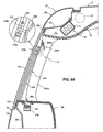
- a sixteenth embodiment will be described referring to FIGS. 40 through 46 .
- a curtain 241 can be stored inside a rear-wheel-house trim 35 (hereinafter, referred to as a "trim 35" ) which is provided below the rear window 12 , as shown in FIGS. 42A, 42B through 44 .
- the curtain 241 is provided so as to be wound up inside the trim 35 by a roll member 217 and to get out of an opening 35a which is formed at the trim 35 below the rear window 12 and move upwards.
- the upper end portion 241a of the curtain 241 is made from a hard material, such as resin, for a proper shape holding or opening/closing operation, and it has a substantially reverse-V shape when viewed from the front.
- the upper end portion 241a has a slant portion 241b which extends obliquely downward and inward.
- Two engaging portions 241c which project toward the rear window 12 are provided near the upper end portion 241a of the curtain 241 . Meanwhile, a pair of rail-shaped support members 18 which extends vertically so as to correspond to the engaging portions 241a is fixed to the inside face of the rear window 12 via the both-side adhesive tape.
- the support member 18 has plural engagement recess portions 18a which are formed along a longitudinal (vertical) direction thereof.
- these engagement recess portions 18a are positioned in such a manner that the upper-located ones are located much closer to the vehicle compartment, as shown in FIGS. 43 and 44 . Consequently, the upper-most portion 18a is located the closest to the vehicle compartment.
- the roll member 217 to wind up the curtain 241 comprises a cylindrical shaft portion 217a to which the base end portion of the curtain 241 is attached and a bearing portion 217b which rotatably support both ends of the shaft portion 217a, as shown in FIGS. 42A, 42B and 46 .
- the shaft portion 217a is biased in a direction of winding up the curtain 241 by a coil spring (not illustrated). Accordingly, the curtain 241 is always kept in a state in which it is biased downwards by the roll member 217.
- the curtain 241 is lowered by a biasing force of the coil spring, so that the curtain 241 is wound up by the roll member 217 and automatically stored inside the trim 35.
- the curtain 241 which has been wound up by the roll member 217 extends substantially in the vehicle longitudinal direction, as shown in FIGS. 42A, 42B , and it is stored in the curtain case member 219 which has a substantially U-shaped cross section, as shown in FIGS. 43 , 44 and 46 .
- the curtain case member 219 which is made from metal or resin, comprises a recess portion 219a which extends longitudinally and stores the roll member 217 and a pair of flange-shaped attaching portions 219b for attaching to the trim 35, as shown in FIG. 46 .
- the attaching portions 219b of the curtain case member 219 which extend substantially horizontally from the both-side ends of the recess portion 219a are fixed to the trim 35 via bolts and nuts of fixing members 219c (see FIG. 46 ).
- the curtain case member 219 is attached to the vehicle body integrally.
- the curtain 241 is withdrawn from the opening 35a toward the rear window 12 when the upper end portion 241a is pulled upwards against the biasing force of the coil spring of the roll member 217.
- the curtain 241 which has been withdrawn upwards can close a specified range of the rear window 12 when the engaging portion 241c engages with one of the engagement recess portions 18a of the support member 18.
- the uppermost engagement recess portion 18a of the support member 18 is positioned on the outside of the outside edge portion of the top ceiling 32 , when the engaging portion 241c of the curtain 241 engages with the engagement recess portion 18a, the position of the curtain 241 , as shown in FIG. 43 , can be kept on the outside of the outside edge portion of the top ceiling 32 as well. Accordingly, the downward inflation of the airbag 21 is not prevented by the curtain 241 . Thus, as shown in FIG. 43 , the airbag 21 inflates smoothly toward the vehicle compartment, thereby achieving the proper protection of the passenger.
- the curtain 241 is stored inside the trim 35 which is provided below the rear window 12 in the open state of the rear window 12 without the curtain 241, the exterior appearance of the vehicle can improve.
- the passenger may operate the curtain 241 easily by grasping the slant portion 241b.
- the curtain 241 is the roll type of curtain which can be wound up by the roll member 217 , the curtain 241 can be stored inside the trim 35 compactly.
- a curtain 242 is a bellows-shaped one which is vertically expandable along a horizontal folding line.
- the curtain 242 can close the rear window 12 .
- the curtain 242 contracts and opens the window 12.
- an engaging portion 242c which corresponds to the engaging portion 241c of the curtain 241 . Accordingly, when the curtain 242 is pulled upwards from the curtain case member 219 and then the engaging portion 241c engages with one of the engagement recess portions 18a of the support member 18, the curtain 242 can close a specified area of the rear window 21.
- one end of a resilient band member 117 which extends vertically, the expansion/contraction direction of the curtain 242, is attached to the upper end portion 242a of the curtain 242 .
- the other end of the resilient band member 117 is fixed to the bottom face of the curtain case member 219 together with the lower end portion of the curtain 242.
- the curtain 242 is biased by the resilient band member 117 so that the upper end portion 242a moves downwards.
- the curtain 242 contracts, as shown in FIG. 48 , and then it is stored in the curtain case member 219 in its folding state.
- a slant portion 242b of the curtain 242 which corresponds to the slant portion 241b of the curtain 241, is stored so as to form a face substantially continuous to the horizontal face portion of the trim 35 around the opening 35a, as shown in FIG. 48 .
- the curtain 242 is withdrawn from the opening 35a toward the rear window 12 when the upper end portion 242a is pulled upwards against the biasing force of the resilient band member 117.
- the position of the curtain 242 can be kept on the outside of the outside edge portion of the top ceiling 32 . Accordingly, the downward inflation of the airbag 21 is not prevented by the curtain 242.
- the curtain 242 is stored inside the trim 35 which is provided below the rear window 12 in the open state of the rear window 12 without the curtain 242 as well, the exterior appearance of the vehicle can improve.
- the present embodiment has other advantages similar to the above-described embodiment.
- a pair of support members 218 is disposed at positions near the upper edges and both sides of the rear window 12 , as shown in FIG. 49 .
- the curtain 241 takes a state in which the engaging portion 241c engages with engagement recess portion 218a, so that the curtain 241 closes the rear window 12 almost fully and another state in which the engagement of the engaging portion 241c with the engagement recess portion 218a is released so that the rear window 12 is fully open without the curtain 241.
- a pair of support members 318 has a connecting piece 318b at its upper portion along with an engagement recess portion 318a, respectively.
- Each connecting piece 318b is connected to the inner panel 33b as the vehicle body.
- the connecting piece 318b extends through a gap between the window glass 12a and the top ceiling 32 to a flange 33b' of the inner panel 33b, and its tip is connected to the flange 33b' preferably via bolt and nut of a fixing member 300.
- a pair of support members 418 is provided at the C pillar 7 and the D pillar 8 near the both sides of the rear window 12, respectively.
- An engagement recess portion 418a is formed to be recessed substantially in the vehicle longitudinal direction as shown. Meanwhile, at an upper end portion 243a of a curtain 243 is provided a hook-shaped engaging portion 243c which projects in the vehicle longitudinal direction so as to correspond to the engagement recess portion 418a, in place of the engaging portion 241c .
- the engaging portion 243c engages with the engagement recess portion 418a.
- the curtain 243 can be supported at its closing state in which the window glass 12a is almost fully closed by the engagement of the engaging portion 243c with the engagement recess portion 418a.
- a slant portion 243b corresponds to the slant portion 241 b of the upper end portion 241a of the previous embodiment.
- both-side end portions of a curtain 244 are supported by rail members 518, 518 which are attached to the C pillar 7 and the D pillar 8 near the side end portions of the rear window 12 so as to extend substantially vertically.
- a curtain hook 244c shown in FIG. 55B is guided by the rail member 518 shown in FIG. 55A so as to slide vertically.
- the curtain hooks 244c are attached to both side portions of an upper end portion 244a of the curtain 244.
- the rail member 518 of the present embodiment corresponds to the support member 18, and the curtain 244 is guided by the rail members 518, 518 so as to move vertically.
- the curtain 244 has an upper end portion 244a, which corresponds to the upper end portion 241 a, and a slant portion 244b which extends obliquely downward and inward at the inside of the upper end portion 244a.
- the curtain 244 can be wound up by the roll member 217 so as to be stored inside the trim 35, and the curtain 244 moves vertically passing through the opening 35a which is formed at the trim 35 below the rear window 12.
- the rail members 518 have a substantially C-shaped cross section and are fixed to the pillar trims 7c, 8c preferably via screws 520...520 at plural portions, as shown in FIGS. 54 and 56 .
- Plural holding portions 518a are formed by part of a bottom face of the rail member 518 which is formed so as to rise, so that the passing distance of the curtain hook 244c is made so narrow that the curtain hooks 244c can be held at this upper position thereof.
- This holding portion 518a functions as a spring in such a manner that when the passenger operates the curtain 244 , the holding portion 518a bends downwards to allow the curtain hook 244c to pass over the holding portion 518a. After the curtain hook 244c has passed upwards over the holding portion 518a, the holding portion 518a engages with the curtain hook 244c and prevents the curtain hook 244c from lowering due to its weight and the biasing force of the coil spring of the roll member 217.
- the rail member 518 is positioned on the outside of the outside edge portion of the top ceiling 32, as shown in FIG. 54 . Accordingly, when the curtain hook 244c of the curtain 244 engages with the holding portion 518a, the position of the curtain 244 can be kept on the outside of the outside edge portion of the top ceiling 32. Accordingly, the downward inflation of the airbag 21 is not prevented by the curtain 241.
- the slant portion 244b which extends obliquely downward and inward is provided at the upper end portion 244a of the curtain 244 , the airbag 21 which inflates from the gap B is guided by the surface of the slant portion 244b towards the vehicle compartment, thereby preventing interference of the airbag 21 with the rail member 518.
- a curtain 245 includes a spring 245d which is expandable substantially in the vehicle longitudinal direction so that the longitudinal length of the curtain 245 is adjustable, as shown in FIG. 58 .
- a rear window 622 (a window glass 622a) is not rectangular unlike the above-described rear window 12 and the like, but it has different longitudinal lengths in the vertical direction, as shown in FIG. 58 .
- the curtain 245 is supported by rail members 618, 618 which are attached to a C pillar 607 (pillar trim 607c) and a D pillar (pillar trim 608c) near the side end portions of the rear window 622 so as to extend vertically.
- Curtain hooks 245c (see FIG. 59 ), which correspond to the curtain hook 244c, are guided by the rail members 618, 618 so as to slide vertically.
- the curtain hooks 245c are attached to the both sides of the upper end portion of the curtain 245 .
- the curtain 245 can move vertically by the guidance of rail members 618, 618.
- the rail member 618 is equipped with a holding portion 618a which corresponds to the holding member 518a of the rail member 518, and holds the curtain 245 in its closing state by engagement of the curtain hook 245c with the holding portion.
- the curtain 245 includes a plurality of springs 245d so that the longitudinal length of the curtain 245 can change according to the tension force of the springs. Further, a pair of frame members 245e which extends vertically is attached to the both-side end portions of the curtain 245 . Respective both ends of the plural springs 245d are connected to the frame members 245e.
- the distance between the rail members 618 changes according to the height position of the curtain 245, and the distance between the frame members 245e and the spring's length changes accordingly. Consequently, the longitudinal length of the curtain 245 changes, so that the whole part of the rear window 622 can be covered with the curtain 245 properly even if the curtain is not of the rectangular shape.
- the curtain hooks 245c and the curtain 245 are lowered by the biasing force of the coil spring of the roll member 217, and the curtain 245 is wound up by the roll member 217 .
- the frame members 245e be so flexible that they can change its shape in the roll shape by the spring force of the roll member 217.
- the curtain 245 of the present embodiment has operating portions 245b, 245b which are made of resin and attached to both ends thereof, instead of the upper end portion 241a .
- the operating portion 245b has a slant face which extends obliquely downward and inward like the slant portion 241b, as shown in FIG. 59 .
- the inflating airbag 21 can be guided towards the vehicle compartment along this slant portion, thereby preventing the interference of the airbag 21 with the rail members 618.
- the present embodiment has the rail members 618 which correspond to the rail members 518, the holding by the curtain hook 245c is released by the inflation of the airbag 21, and accordingly the airbag 21 can be allowed to inflate downwards quickly by means of the inflation pressure like the above-described twenty-first embodiment. Thus, the smooth inflation of the airbag 21 is not prevented by the curtain 245.
- a blind 246 in place of the curtain 241 or the like, which is made of plural plates 246A which extend substantially in the vehicle longitudinal direction and are connected to each other via connecting bands 246d , as shown in FIGS. 60 and 61 .
- the plural plates 246A of the blind 246 are disposed side by side in the vertical direction, and they are connected via a pair of connecting bands 246d which extends vertically at their both-side end portions. Accordingly, when the passenger pulls an upper end portion 246a in the vehicle longitudinal direction, the adjacent plates 246A move longitudinally relatively like a step shape as shown, so that the blind 246 substantially forms a shape of parallelogram as shown.
- a whole of the rear window 722 can be covered with the blind 722.
- the blind 246 is wound up by the roll member 217 and then stored inside the trim 35, as shown in FIG. 60 , like the curtain 241 and the like.
- the blind 246 can be made move up and down passing through the opening 35a, and it is configured to be always biased downwards by the roll member 217.
- a pair of engaging portions 246c which corresponds to the engaging portion 241 c of the curtain 241, is attached to positions which are near the upper end portion 246a of the blind 246 .
- a pair of support members 718, 718 which have engagement recess portions 718a so as to correspond to the engaging portions 246c.
- a guide roller 730 is provided at one end of the opening 35a, as shown in FIG. 60 .
- the blind 246 is forced to lower by the biasing force of the coil spring.
- one-side ends of the plates 246A come to contact the guide roller 730, and thereby the guide roller 730 is driven. Accordingly, each of the plates 246A is guided to the opening 35a by the guide roller 730 properly, so that the blind 246 is wound up properly by the roll member 217.
- a support member 818 is made from or comprises a magnet, as shown in FIG. 62 , which has no engagement recess portion. Thereby, the covering area of the rear window 12 with the curtain 241 can be adjusted more properly. Further, since there is no need to form the engagement recess portion like the portions 18a of the support member 18 and the like of the above-described embodiments, forming the support member may be simple.
Landscapes
- Engineering & Computer Science (AREA)
- Mechanical Engineering (AREA)
- Air Bags (AREA)
Abstract
Description
- The present invention relates to an attachment structure of a curtain-shaped cover member which is provided at a window of a vehicle.
- Some vehicles have been recently equipped with a curtain airbag device to protect a passenger from a side impact load, in addition to an airbag device to protect a passenger from a frontal impact load. In the curtain airbag device, an airbag is stored in a vehicle longitudinal direction at a portion above a window or at an upper portion of a pillar which forms a side face of a vehicle body, and the airbag inflates receiving a gas pressure from an inflator when the side impact load acts from the vehicle side. Herein, the airbag may inflate downwards along a window glass or an inner face of the pillar, pressing down or breaking part of a top ceiling which covers a roof panel from the inside of a vehicle compartment, for example.
- Meanwhile, a cover member, such as a curtain or blind, which can shut out person's eyes from the vehicle outside may be optionally provided at a side face of the vehicle body beside a rear seat or a rear window in order to ensure a privacy of the passenger in the vehicle compartment or the like. Japanese Patent Laid-Open Publication No.
11-48902 - Herein, in case the airbag is configured to inflate downwards through a gap which is formed between the window glass and the side end portion of the top ceiling which is pressed down by the inflating airbag when the curtain airbag device is operated, if the above-described cover member, such as the curtain or the blind, is provided at the window, the following problem may occur.
- While this kind of cover member generally hangs on the side end portion of the top ceiling beside the window, in case the above-described structure of the curtain airbag device is provided, the airbag of the curtain airbag device may improperly inflate into a space between the cover member and the window glass, resulting in breaking the cover member or forcing the cover member to move toward the inside of the vehicle compartment. Accordingly, a smooth inflation of the airbag would be deteriorated. As a result, it would be actually difficult for the cover member, such as the curtain, to be provided at the window in case the curtain airbag device is provided.
- This problem may occur in a situation in which the curtain airbag device is provided at the upper portion of the vehicle-body rear face, for example, a back door, and the airbag inflates downwards along a window glass of a rear window of the vehicle-body rear face.
- Accordingly, an object of the present invention is to provide an attachment structure of a curtain-shaped cover member of a vehicle equipped with the curtain air bag device which can allow the airbag to inflate properly and smoothly.
- The object is solved by the features of the independent claims. Preferred embodiments of the present invention are subject of the dependent claims.
- According to the present invention, there is provided an attachment structure of a curtain-shaped cover member of a vehicle, comprising a top ceiling covering, preferably a soft top ceiling covering, a roof panel from an inside of a vehicle compartment, a side end portion of which points to near an upper edge portion of a window glass of a window which is formed at a vehicle body, a curtain-shaped cover member provided to cover at least an upper portion of the window glass from the inside of the vehicle compartment, a curtain airbag device provided near an upper portion of the window, the curtain airbag device including an airbag which is stored along the upper edge portion of the window glass in a non-operation state of the curtain airbag device and inflates substantially downwards through a gap which is formed between the window glass and the side end portion of the top ceiling which is pressed substantially downwards by the airbag receiving a gas pressure from an inflator, and a support member to support the curtain-shaped cover member at a position which is on an outside and/or lower side of the inflating airbag.
- According to the present invention, since the cover member is supported at the position which is on the outside and/or lower side of the inflating airbag, the airbag can inflate substantially downwards along an inside face of the cover member without getting into the space between the window glass and the cover member. As a result, the airbag can inflate smoothly to perform its function properly.
- Herein, according to an embodiment of the present invention, the support member supports the cover member so that the cover member can move substantially in a vehicle longitudinal direction.
- According to another embodiment of the present invention, the support member supports the cover member so that the cover member can move substantially in a vertical direction. Accordingly, even if the inflating airbag contacts the cover member, the cover member can be allowed to move downwards properly by the support member. As a result, the airbag can inflate smoothly to perform its function properly.
- According to another embodiment of the present invention, the attachment structure of a curtain-shaped cover member of a vehicle further comprises a rear pillar which is positioned behind the window and covered with a rear pillar trim, which is preferably made from hard resin, from the inside of the vehicle compartment, wherein the curtain airbag device is fixed to the vehicle body along a specified portion of the rear pillar, the airbag inflates out of a space between the window and an outside end portion of the rear pillar trim so as to cover the window from the inside of the vehicle compartment, and/or there is provided a holding member to hold a rear end portion of the cover member at a position which is on an outside of the inflating airbag. Thereby, the rear end portion of the cover member can be surely positioned on the outside of the inflating airbag by the holding member, so that the airbag can inflate smoothly to perform its function properly.
- According to another embodiment of the present invention, the rear pillar preferably comprises an inner panel and an outer panel, a holding bracket which extends substantially forward is preferably provided at the inner panel, and the holding member is provided at the holding bracket. Thereby, the holding member can be fixed firmly to the vehicle body via the bracket, so the rear end portion of the cover member can be held firmly.
- According to another embodiment of the present invention, the holding member is attached to the window. Thereby, the holding member can be provided without any particular bracket, so the number of parts and costs can be reduced.
- According to another embodiment of the present invention, the cover member is biased forward or downward, and/or engagement of the holding member with the cover member is released according to an inflation of the airbag. Thereby, the cover member is provided so as to move forward from the rear pillar according to the inflation of the airbag, so that the cover member does not prevent the inflation of the airbag surely.
- According to another embodiment of the present invention, a trim is provided below the window, and the cover member is stored inside the trim in an open state thereof. Thereby, since the cover member is hidden inside the trim below the window, the exterior appearance of the vehicle can be improved.
- According to another embodiment of the present invention, the support member is positioned on an outside of the side end portion of the top ceiling when the curtain airbag device is in the non-operation state. Thereby, the side end portion of the top ceiling which is pressed downwards by the inflating airbag can be prevented from contacting the support member.
- According to another embodiment of the present invention, a support position of the cover member is located on an outside of a moving locus of the side end portion of the top ceiling which is pressed downwards according to an inflation of the airbag. Thereby, preventing the contact of the side end portion of the top ceiling with the support member can be achieved surely.
- According to another embodiment of the present invention, there is provided an interference preventing member to prevent interference of the support member with the inflating airbag at an upper portion of the support member. Thereby, the interference of the support member with the inflating airbag can be prevented.
- According to another embodiment of the present invention, a middle pillar is provided in front of the window with the window glass and a rear pillar is provided in back of the window with the window glass.
- According to another embodiment of the present invention, the support member is a rail member which is attached to the window glass so as to extend in a vehicle longitudinal direction at an upper portion of the window. Thereby, the upper portion of the covering member can be kept adjacent to the upper portion of the window glass. Accordingly, it can be prevented surely that the airbag inflates into the space between the window glass and the cover member.
- According to another embodiment of the present invention, another rail member is attached to the window glass so as to extend in the vehicle longitudinal direction at a lower portion of the window, and the cover member is preferably supported by both the rail members. Thereby, a whole part of the cover member inflates along the window glass. Accordingly, the airbag can inflate along the window glass on the inside of the cover member.
- According to another embodiment of the present invention, a middle pillar is provided in front of the window with the window glass and a rear pillar is provided in back of the window with the window glass, and the support member has a fixing portion on at least one of a front end and a rear end thereof, the fixing portion being preferably fixed to the middle pillar and/or the rear pillar. Thereby, the support member can be fixed firmly, compared to a case in which it is fixed to the window glass.
- According to another embodiment of the present invention, the middle pillar is provided in front of the window with the window glass and the rear pillar is provided in back of the window with the window glass, and the support member is a pair of rail members which is attached to the pillars. Thereby, the downward movement of the cover member can be achieved surely when the inflating airbag contacts the cover member, without any particular structure for providing the support member.
- According to another embodiment of the present invention, a holding portion to hold the cover member is provided at an upper portion of the support member, and holding of the cover member by the holding portion is released when the airbag inflates and contacts an upper portion of the cover member. Accordingly, opening or closing of the window with the cover member can be properly achieved at a normal state, and when the curtain airbag device operates, the airbag can inflate properly.
- According to another embodiment of the present invention, the cover member is biased downwards. Accordingly, the downward movement of the cover member by the contact of the inflating airbag is assisted. Thus, the cover member can move quickly to the inflation of the airbag, thereby further improving the smooth inflation.
- According to another embodiment of the present invention, a treatment to prevent exposure of the support member to a vehicle outside is applied to a specified portion of the window glass where the support member is attached. Thereby, the exterior appearance of the vehicle can improve.
- According to another embodiment of the present invention, a slant member which extends obliquely downward and inward is provided at an upper portion of the cover member. Thereby, the passenger may operate the cover member easily by grasping the slant member. Further, the inflation of the airbag can be properly guided toward the vehicle compartment along the face of the slant member. Moreover, any interference of the inflating airbag with the support member can be prevented by the slant member.
- According to another embodiment of the present invention, the cover member is a roll type of curtain member. Thereby, the cover member can be stored inside the trim compactly.
- According to another embodiment of the present invention, the cover member includes a resilient member which is expandable in a vehicle longitudinal direction so that a longitudinal length thereof is adjustable. Thereby, the whole part of the window can be covered with the cover member.
- According to a further aspect, there is provided a vehicle having an attachment structure, as described above.
- According to a further aspect, there is provided a method of attaching a curtain-shaped cover member of a vehicle , comprising the steps of:
- providing the curtain-shaped cover member so as to cover at least an upper portion of a window glass of a window from an inside of a vehicle compartment; and
- supporting the curtain-shaped cover member by means of a support member at a position which is on an outside and/or a lower side of an inflating airbag of a curtain airbag device provided near an upper portion of the window.
- Other features, aspects, and advantages of the present invention will become apparent from the following description which refers to the accompanying drawings.
-
FIG. 1 is a schematic inside view of a vehicle compartment of a vehicle to which the present invention is applied. -
FIG. 2 is a sectional view of a support member of a curtain when an airbag is stored according to a first embodiment of the present invention, when viewed in a vehicle longitudinal direction. -
FIG. 3A is a view of the curtain which has inflated;FIG. 3B is a view of the curtain which is stored, according to the first embodiment of the present invention. -
FIG. 4 is a view to show a position of rail members. -
FIG. 5 is another view to show the position of the rail members. -
FIG. 6 is a sectional view of the support member of the curtain when the airbag inflates according to the first embodiment of the present invention, when viewed in the vehicle longitudinal direction. -
FIG. 7 is a sectional view of a support member of the curtain according to a second embodiment, when viewed from a ceiling side. -
FIG. 8 is a sectional view of a support member of the curtain according to a third embodiment, when viewed in the vehicle longitudinal direction. -
FIG. 9 is a sectional view of a support member of the curtain according to a fourth embodiment, when viewed in the vehicle longitudinal direction. -
FIG. 10 is a sectional view of a support member of the curtain according to a fifth embodiment, when viewed in the vehicle longitudinal direction. -
FIG. 11 is a sectional view of another support member of the curtain according to the fifth embodiment, when viewed in the vehicle longitudinal direction. -
FIG. 12 is a sectional view of a support member of the curtain according to a sixth embodiment, when viewed in the vehicle longitudinal direction. -
FIG. 13 is a view of a support member of the curtain according to a seventh embodiment. -
FIG. 14 is a sectional view of another support member of the curtain according to the seventh embodiment, when viewed in the vehicle longitudinal direction. -
FIG. 15 is a sectional view of another support member of the curtain according to the sixth embodiment, when viewed in the vehicle longitudinal direction. -
FIG. 16 is a schematic inside view of a vehicle compartment of a vehicle according to an eighth embodiment of the present invention, which shows each open state of curtains. -
FIG. 17 is a schematic inside view of the vehicle compartment of the vehicle according to the eighth embodiment of the present invention, which shows each closed state of the curtains. -
FIG. 18 is a sectional view of surroundings of a rear window. -
FIG. 19A is an elevation view of the rear window with the curtain closed;FIG. 19B is an elevation view of the rear window with the curtain open. -
FIG. 20 is a sectional view taken along line X-X ofFIG. 19A . -
FIG. 21 is a view showing a state in which the airbag inflates. -
FIGS. 22A, 22B are elevation views of the rear window according to a ninth embodiment, which corresponds toFIG. 19A, 19B , respectively. -
FIG. 23 is a sectional view taken along line Y-Y ofFIG. 22A . -
FIGS. 24A, 24B are elevation views of the rear window according to a tenth embodiment, which corresponds toFIG. 19A, 19B , respectively. -
FIG. 25 is a sectional view taken along line Z-Z ofFIG. 24A . -
FIG. 26A is a sectional view of a second rail member and its surroundings, when viewed in the vehicle longitudinal direction;FIG. 26B is a horizontal sectional view of the second rail member and its surroundings. -
FIG. 27 is a sectional view showing a state in which the airbag inflates. -
FIG. 28 is a partial sectional view of a snap member according to an eleventh embodiment of the present invention. -
FIG. 29 is a schematic inside view of the vehicle compartment of a vehicle to which a twelfth embodiment of the present invention is applied. -
FIG. 30A is an elevation view of a rear window showing a closed state of a curtain;FIG. 30B is an elevation view of the rear window showing an open state of the curtain according to the twelfth embodiment. -
FIG. 31 is an enlarged sectional view taken along line X-X ofFIG. 30A . -
FIG. 32 is an enlarged sectional view taken along line Y-Y ofFIG. 30A . -
FIG. 33 is an enlarged sectional view taken along line Z-Z ofFIG. 32 . -
FIG. 34 is a sectional view showing the inflation state of the airbag, which corresponds toFIG. 31 . -
FIG. 35 is an elevation view of the rear window according to a thirteenth embodiment. -
FIG. 36 is an enlarged sectional view of an upper portion of a rail member of the present embodiment. -
FIG. 37 is an enlarged sectional view of a curtain according to a fourteenth embodiment. -
FIG. 38 is an elevation view of the rear window according to a fifteenth embodiment. -
FIG. 39 is an enlarged sectional view of a curtain according to the present embodiment. -
FIG. 40 is a schematic inside view of the vehicle compartment of a vehicle according to a sixteenth embodiment of the present invention, which shows a state in which curtains are open. -
FIG. 41 is a schematic inside view of the vehicle compartment of a vehicle according to the sixteenth embodiment of the present invention, which shows a state in which the curtains are closed. -
FIG. 42A is an elevation view of the rear window showing the closed state of the curtain;FIG. 42B is an elevation view of the rear window showing the open state of the curtain. -
FIG. 43 is an enlarged sectional view taken along line X1-X1 ofFIG. 42A . -
FIG. 44 is an enlarged sectional view taken along line X2-X2 ofFIG. 42B . -
FIG. 45 is an enlarged sectional view taken along line Y1-Y1 ofFIG. 42A . -
FIG. 46 is an enlarged sectional view of a major portion of an attaching structure of a curtain case member. -
FIG. 47 is a sectional view of the rear window vehicle according to a seventeenth embodiment of the present invention, which corresponds toFIG. 43 . -
FIG. 48 is an enlarged sectional view of a major portion of an attaching structure of a curtain case member. -
FIG. 49 is an elevation view of the rear window according to an eighteenth embodiment of the present invention. -
FIG. 50 is an elevation view of the rear window according to a nineteenth embodiment of the present invention. -
FIG. 51 is an enlarged sectional view of a major portion of an attaching structure of the cover member. -
FIG. 52 is an elevation view of the rear window according to a twentieth embodiment of the present invention. -
FIG. 53 is an elevation view of the rear window according to a twenty-first embodiment of the present invention. -
FIG. 54 is a sectional view of the rear window vehicle, which corresponds toFIG. 43 . -
FIG. 55A is a perspective view of a rail member;FIG. 55B is an exploded perspective view of an attaching structure of a curtain hook. -
FIG. 56 is a sectional view of the attaching structure of the curtain hook. -
FIG. 57 is a sectional view of the inflating airbag, which corresponds toFIG. 43 . -
FIG. 58 is an elevation view of the rear window according to a twenty-second embodiment of the present invention. -
FIG. 59 is a sectional view of the upper portion of the rear window and surroundings of an upper end portion of a curtain, which corresponds toFIG. 43 . -
FIG. 60 is an elevation view of the rear window according to a twenty-third embodiment of the present invention. -
FIG. 61 is a sectional view of the upper portion of the rear window and surroundings of an upper end portion of a curtain, which corresponds toFIG. 43 . -
FIG. 62 is an elevation view of the rear window according to a twenty-fourth embodiment of the present invention. - Hereinafter, preferred embodiments of the present invention will be described. Although the embodiments are described separately, it should be understood that single or plural feature(s) of one embodiment may be combined with one or more of the other embodiment(s).
- As shown in
FIG. 1 , there are provided afront seat 2, a second-row seat 3 and a third-row seat 4 in a vehicle compartment of avehicle 1 according to a first embodiment. Further, anA pillar 5, aB pillar 6, aC pillar 7 and aD pillar 8 are provided at a side face of thevehicle 1. Afront side door 9 is disposed between theA pillar 5 and theB pillar 6, and arear side door 10 is disposed between theB pillar 6 and theC pillar 7. Aback door 11 is provided at a vehicle-body rear face. -
Window glasses side doors back door 11, respectively. Herein, thewindow glasses side doors window glass 11a of theback door 11 is fixed without opening. Further, arear window 12 is formed between theC pillar 7 and theD pillar 8, and a fixedwindow glass 12a is provided at thisrear window 12. Moreover,curtains rear side door 10, theback door 11, and therear window 12 respectively so as to cover thewindow glasses - Meanwhile, in addition to an airbag device (not illustrated) which protects a passenger seated in the
front seat 2 from the frontal impact load, acurtain airbag device 20 which protects passengers seated on theseats vehicle 1. - The
curtain airbag device 20 comprises anairbag 21 and an inflator 23 as shown inFIG. 2 . Theairbag 21 is stored in the vehicle longitudinal direction along an upper edge portions of thewindow glasses front side door 9, therear side door 10 and therear window 12 at a specified position above a side end portion of a top ceiling (roof trim) 32 which covers aroof panel 31 from the inside of the vehicle compartment and is preferably formed as a soft top ceiling. The inflator 23 supplies an inflatable gas pressure to theairbag 21 via asupply passage 22. - When the side impact load acts from the side or its action is predicted, the
airbag 21 receives the gas pressure from the inflator 23 and inflates downwards along thewindow glasses side end portion 32a of thetop ceiling 32 which is pressed down by the inflatingairbag 21, thereby protecting the passengers seated in theseats - Herein, the
curtain 13 which is provided at therear door 10 is positioned on the outside of the above-described gap through which theairbag 21 inflates, so that thecurtain 13 may not be any obstacle for the airbag inflating. However, since thecurtain 14 of therear window 12 is positioned almost below the gap, there is a concern that thecurtain 14 would prevent the inflation of theairbag 21. - As countermeasures for this concern, the
curtain 14 is supported bysupport members window glass 12a so that it can be located adjacent to thewindow glass 12a of therear window 12, specifically it can be positioned on the outside of the inflatingairbag 21 in the vehicle width direction. - The
window glass 12a to which thesupport members flange 33a' of anouter panel 33a which forms a part of aroof side rail 33 and aflange 34a' of anouter panel 34a which forms a part of arear fender 34. - The
curtain 14 is supported by thesupport members curtain 14 is positioned above an inflation direction D of theairbag 21 of thecurtain airbag device 20, as shown inFIG. 2 . - The
support members curtain 14, which are preferably rail members extending substantially in the vehicle longitudinal direction, supports the curtain horizontally. Themember 14a is fixed to an upper portion of thewindow glass 12a, and themember 14b is fixed to a lower member of thewindow glass 12a in parallel to themember 14a (seeFIG. 3A , a view of the curtain which has inflated;FIG. 3B , a view of the curtain which is stored). Fixing of these rails may be conducted by means of a both-side adhesive tape. - The
upper rail member 14a supports a portion of thecurtain 14 which is located slightly below an upper end of thecurtain 14, and thelower rail member 14b supports a lower end of thecurtain 14. This position of theupper rail member 14a is located so that theside end portion 32a of thetop ceiling 32 does not contact therail member 14a when theairbag 21 inflates. - Specifically, as shown in
FIG. 4 , theupper rail member 14a is fixed to thewindow glass 12a at a position which is a specified distance L away from theside end portion 32a toward the vehicle outside when thecurtain airbag device 20 is not operated. Thereby, it can be prevented that therail member 14a contacts theside end portion 32a of thetop ceiling 32 which may be pressed down by the inflatingairbag 21. - Herein, it may be preferable that the
rail member 14a be fixed to thewindow glass 12a so that the support position of thecurtain 14 by therail member 14a is located on the outside of a moving locus R of the side end portion of thetop ceiling 32 which is pressed down according to the inflation of theairbag 21. Thereby, the contact of theside end portion 32a of thetop ceiling 32 which may be pressed down according to the inflation of theairbag 21 with therail member 14a can be prevented surely. - Hereinafter, the inflation of the
airbag 21 at the position of thecurtain 14 will be described. At first, theairbag 21 starts to inflate, then theside end portion 32a of thetop ceiling 32 is pressed down by the inflatingairbag 21. - Herein, while the
side end portion 32a of thetop ceiling 32 contacts thecurtain 14a, the upper end of thecurtain 14 may return to its original position after theside end portion 32a has moved toward the inside of the vehicle compartment to some extent. - Specifically, the vertical (vehicle-height direction) length of the
curtain 14 is set so that the upper end of thecurtain 14 can return to its original position after the contact with theside end portion 32a by the time theairbag 21 has inflated beyond theside end portion 32a of thetop ceiling 32. This is because if the above-described length was too long, there is a possibility that theairbag 21 may inflate beyond theside end portion 32a of thetop ceiling 32 which contacts the upper end of thecurtain 14 and then inflate into a space between thewindow glass 12a and thecurtain 14. - As the
airbag 21 further inflates, theside end portion 32a of thetop ceiling 32 moves toward the inside of the vehicle compartment, and theairbag 21 goes beyond theside end portion 32a of thetop ceiling 32 and inflates on the inside of the vehicle compartment. Theairbag 21 inflates downwards along the inside face of thecurtain 14. Then, as shown inFIG. 6 , theairbag 21 fully inflates, resulting in covering thewindow glass 12a of thewindow 12. - According to the present embodiment, since the
curtain 14 is supported by therail members airbag 21 in the vehicle width direction, theairbag 21 can inflate downwards along the inside face of thecurtain 14 without getting into the space between thewindow glass 12a and thecurtain 14. As a result, theairbag 21 can inflate smoothly to perform its function properly. - Further, since the upper portion of the
curtain 14 is supported by theupper rail member 14a, it can be kept adjacent to the upper portion of thewindow glass 12a. Accordingly, it can be prevented surely that theairbag 21 inflates into the space between thewindow glass 12a and thecurtain 14. - Moreover, since the
curtain 14 is supported by the upper andlower rail members curtain 14 inflates along thewindow glass 12a. Accordingly, theairbag 21 can inflate smoothly along thewindow glass 12a on the inside of thecurtain 14. - While the rail members to support the curtain as the support member are fixed to the window glass by means of the both-side adhesive tap in the above-described embodiment, they are fixed to a vehicle-body member in a second embodiment.
-
FIG. 7 is a view ofrail member 114a (114b) attached according to the present embodiment, when viewed from a ceiling side. Therail member 114a (114b) extends on the vehicle longitudinal direction and supports acurtain 114 horizontally. This rail member is not fixed to thewindow glass 112a by means of the both-side adhesive tape, but its one end is fixed to a pillar trim 107a which forms aC pillar 107 and the other end is fixed to a pillar trim 108a which forms aD pillar 108 bybolts 114d, respectively. - According to the present embodiment, the
rail members window 112. Thereby, fixing of the rail members may be made properly firm, compared to the fixing by means of the both-side adhesive tape. This embodiment may be effective for the opening type of window glass. - Herein, if such firm fixation is not required very much, the both ends of the rail member may be fixed to the both pillar trims by the both-side adhesive tape. In this case, if the curtain is not provided at the window optionally (in case the rail member is not fixed to the pillar trim), the design of the pillar trim may not be deteriorated. In case the fixing is conducted by the bolt, a bolt hole to be formed at the pillar trim may not be hidden unless the curtain is provided, resulting in damaging the design.
- While the both rail members as the support member to support the curtain of the first embodiment are fixed to the window glass, they are fixed to the pillar trims according to the second embodiment. The present invention should not be limited to these. According to a third embodiment, one of them is fixed to the window glass and the other is fixed to the vehicle-body member.
-
FIG. 8 is a sectional view ofrail members - An
upper rail member 214a extends in the vehicle longitudinal direction and is fixed to an upper portion of awindow glass 212a (which is fixed by means of the both-side adhesive tape like the first embodiment). Alower rail member 214b extends in the vehicle longitudinal direction and is fixed to a rear wheel-house trim 235 which is positioned below a window 212 (which is fixed by means of the both-side adhesive tape or bolt like the second embodiment). Herein, not limited to these, one of the rails may be attached to the upper portion of the window glass, and the other may be attached to the pillar trims at its both ends. - The present embodiment may be effective in case it is difficult for the both rail members to be attached to the window glass or the vehicle-body member.
- According to a fourth embodiment, the two rail members are firmly fixed to another vehicle-body member than the pillar trims.
-
FIG. 9 is a sectional view ofrail members - An
upper rail member 314a extends substantially in the vehicle longitudinal direction and is fixed to aninner panel 333b which forms a part of aroof side rail 333 which supports an upper end of awindow glass 312a. Specifically, a part of theinner panel 333b extends toward the inside of the vehicle compartment (window 312) at the upper portion of thewindow glass 312a, and theupper rail member 314a is attached to this extending portion. - Meanwhile, a
lower rail member 314b is fixed to aninner panel 334b which forms a part of arear fender 334 which supports a lower end of thewindow glass 312a. Specifically, a part of theinner panel 334b extends toward the inside of the vehicle compartment (window 312) at the lower portion of thewindow glass 312a, and thelower rail member 314b is attached to this extending portion. - The present embodiment may be effective in case the curtain is always provided at the window, not optionally. The rail members can be fixed firmly.
- A fifth embodiment is an example in which rail members attached to the window glass is not visible from the vehicle outside.
-
FIG. 10 is a sectional view ofrail members - Two
rail members ceramic coat 412b which is applied at a periphery of an inner face of awindow glass 412 by means of the both-side adhesive tape, for example. In other words, to an attachment portion of therail members ceramic coat 412b to prevent exposure of therail members - According to the present embodiment, since the
ceramic coat 412b prevents therail members - Herein, in place of the ceramic coat, a
color film 512b, such as an infrared shut-off film, may be stuck on the inside face of awindow glass 512, and therail members film 512b, as shown inFIG. 11 . In this alternative, likewise, therail members - A sixth embodiment shows an example to cope with a case in which there occurs interference of the rail member with the inflating airbag.
-
FIG. 12 is a sectional view of a rail member according to the present embodiment, when viewed in the vehicle longitudinal direction. - As shown in
FIG. 12 , arail member 614a extends in the vehicle longitudinal direction and supports acurtain 614 in such a manner that thecurtain 614 hangs on awindow 612. Thus, there is a concern that the inflating airbag would contact the rail member directly, compared to the case shown inFIG. 2 in which the rail member supports the portion of the curtain which is located slightly below the upper end of the curtain. This would deteriorate the smooth inflation of the airbag. - Thus, according to the present embodiment, there is provided an
interference preventing member 614e which prevents interference of therail member 614a with an inflatingairbag 621, i.e., which avoids a direct contact of these members, at an upper portion of therail member 614a. Thisinterference preventing member 614e also performs function of assisting the inflation of theairbag 621 toward the inside of the vehicle compartment, that is, it guides theairbag 621 inflating toward therail member 614a toward the inside of the vehicle compartment, in addition to preventing the above-described interference. Therefore, thismember 614e has aguide face 614e'. Thereby, theairbag 621 is prevented from interfering with therail member 614a, and its inflation direction is changed from a direction toward therail member 614a to a direction toward the inside of the vehicle compartment. - Herein, of course, interference of the
interference preventing member 614e with aside end portion 632a of atop ceiling 632 which is pressed down by the inflatingairbag 614e is avoided (considering this, therail member 614a is fixed to thewindow glass 612a). - According to the present embodiment, the interference of the
rail member 614a with the inflatingairbag 621 can be prevented by theinterference preventing member 614e provided at the upper portion of therail member 614a. - Herein, while the
rail member 614a with theinterference preventing member 614e of the embodiment described above supports thecurtain 614 in such a manner that thecurtain 614 hangs, the rail member may be configured to support the curtain horizontally as shown inFIG. 15 , which is like the first through fifth embodiments. Herein, in case aninterference preventing member 914e is equipped with aguide face 914e' like theinterference preventing member 914e of the embodiment described above, it may be preferable that an upper end of acurtain 914 be supported horizontally by arail member 914a. This is because if the curtain is supported at the specified portion thereof which is located slightly below its upper like the above-described first through fifth embodiments, the curtain may be some obstacle for the inflating airbag which is guided by the guide face toward the inside of the vehicle compartment. - A seventh embodiment is an example in which the support member to support the curtain is not a rail member.
- In the present embodiment,
snap buttons 714a are used as the support member to support acurtain 714 as shown inFIG. 13 . Thesnap button 714a comprises a convex (or concave)button 714a' which is fixed to awindow glass 712, and abutton 714a" which is fixed to thecurtain 714 so as to engage with thebutton 714a'. - The present embodiment performs the similar function like the rail members described above, and in case the curtain becomes unnecessary, it can be removed from the window easily.
- Herein, it may be preferable that an
interference preventing member 814e be provided above asnap button 814a, as shown inFIG. 15 , as an alternative embodiment like the above-described sixth embodiment in case the support member possibly has a possibility of the interference with the inflating airbag. In this case, aguide face 814e' of theinterference preventing member 814e guides the inflation of an airbag 821 toward the inside of the vehicle compartment, and the direct contact of the airbag 821 with thesnap button 814a can be avoided by thismember 814e. - The present invention should not be limited to the above-described embodiments. For example, while two rail members are provided in the above-described embodiments, only a single member to support the upper portion of the window glass may be applied instead of the two in case the window glass is provided so as to extend substantially vertically. This is because the curtain may properly hang along a whole part of the window glass without a lower rail member, so that the airbag can inflate smoothly.
- Hereinafter, some alternatives of the above-described first embodiment which are equipped with a holding member (snap member) to hold a rear end portion of the curtain at a position which is on the outside of the inflating airbag will be described as eighth through eleventh embodiments. The same components\parts as those of the first embodiment are denoted by the same reference characters, and detailed descriptions of those will be omitted.
- An eighth embodiment will be described referring to
FIGS. 16 through 21 . In the present embodiment, there are providedtethers A pillar 5 and theD pillar 8 and the other ends of which are the front end and the rear end of theairbag 21, respectively. Theairbag 21 is configured such that its rear end portion extends to the inside of theD pillar 8 and is covered with a trim 8c from the inside of the vehicle compartment as shown inFIGS. 19A, 19B . Further, the rear end portion of theairbag 21 is fixed to the vehicle body along a specified portion (a front side portion) of theD pillar 8 when the airbag is stored. Thetethers A pillar 5 and the D pillar when theairbag 21 is stored. Thetethers airbag 21. Thereby, a tension line is formed at theairbag 21 in the vehicle longitudinal direction, thereby applying a tension to theairbag 21 to improve the protection of the passenger. -
FIG. 20 is a sectional view taken along line X-X ofFIG. 19A . As shown inFIGS. 19A, 19B and20 , two vehicle-bodyside snap members snap member 15a") are provided near afront edge portion 8c' of the trim 8c, i.e., near a rear side portion of therear window 12. Meanwhile, two curtain-side snap members snap member 15b") which correspond to the vehicle-bodyside snap members curtain 14. - Herein, by connecting the
snap members snap members curtain 14 is held at a specified position with thesnap members rail members FIG. 20 . - The
C pillar 7 and theD pillar 8 have closed cross sections which are formed byouter panels inner panels FIG. 20 . The above-describedsnap member 15a is attached to the vehicle body (inner panel 8b) via aresin bracket 17 which is fixed to theinner panel 8b of theD pillar 8 with a fixingmember 16 of a bolt and a nut. - Specifically, a rear end portion of the
bracket 17 is fixed to theinner panel 8b with the fixingmember 16, meanwhile a front end portion of thebracket 17 extends substantially forward along thewindow glass 12a of therear window 12. A tip of the front end portion extends into the inside of the vehicle compartment through a gap between theinner panel 8b and the trim 8c, and thesnap member 15a is attached to this tip of the front end portion. Thus, the passenger can connect or disconnect thesesnap members - The rear end portion of the
airbag 21 is stored in a space between theinner panel 8b of theD pillar 8a and the trim 8c as shown. When theairbag 21 inflates, as shown inFIG. 21 , thefront edge portion 8c' of the trim is opened by the inflating airbag toward the inside of the vehicle compartment. Then, theairbag 21 inflates forward along thewindow glass 12a, getting out of a gap G which is formed near thefront edge portion 8c' opened. - According to the present embodiment, herein, by connecting the
snap members curtain 14 is held at the position which is on the outside of thefront edge portion 8c' of the trim 8c, i.e., on the outside of inflation position of theairbag 21, as shown inFIG. 21 . Accordingly, since thecurtain 14 is located on the outside of inflatingairbag 21, the forward inflation of theairbag 21 is not prevented by thecurtain 14. Consequently, the airbag can inflate toward the inside of the vehicle compartment smoothly, thereby achieving the protection of the passenger. Further, the tether 25 (seeFIGS. 16 and17 ) inflates toward the inside of the vehicle compartment through the gap G which is formed according to the inflation of the rear end portion of theairbag 21 at the rear end portion of theairbag 21. Moreover, since thesnap member 15a can be firmly fixed to the vehicle body via thebracket 17 by providing thesnap member 15a at thebracket 17 which extends forward from theinner panel 8b of theD pillar 8, the rear end portion of thecurtain 14 can be held firmly. - A ninth embodiment will be described referring to
FIGS. 22A, 22B and23 .FIGS. 22A, 22B are elevation views of the rear window according to the ninth embodiment, which corresponds toFIG. 19A, 19B .FIG. 23 is a sectional view taken along line Y-Y ofFIG. 22A . - In the present embodiment,
snap members 115a, which correspond to thesnap member 15a, are fixed onto a rear portion of the inside face of thewindow glass 12a of therear window 12, which is near thefront edge portion 8c' of the trim 8c. This fixing is conducted by the both-side adhesive tape. - Similarly to the eight embodiment, by connecting the
snap members curtain 14 which covers therear window 12 is held at the position which is on the outside of thefront edge portion 8c' of the trim 8c, i.e., on the outside of theairbag 21 and thetether 25 as shown inFIG. 23 . - Accordingly, the inflation of the
airbag 21 is not prevented. Further, since thesnap members 115a are directly attached to thewindow glass 12a, it can be provided without any particular member like thebracket 17 of the eighth embodiment. As a result, the number of parts and costs can be reduced. - A tenth embodiment will be described referring to
FIGS. 24A, 24B through 27 . - In the present embodiment, as shown in FIGS. 9A, 9B, a
resilient band 114c which extends substantially in the vehicle longitudinal direction is attached to thecurtain 14 so that the front end and the rear end of thecurtain 14 are biased rearward and forward, respectively. -
Snap members 215a, which correspond to thesnap member 15a, are supported atsecond rail members window glass 12a of therear window 12, which is near thefront edge portion 8c' of the trim 8c, as shown inFIGS. 24A, 24B and25 . - Specifically, each of the
snap members 215a is attached to aslider 219 which is supported at thesecond rail member 220 so as to slide longitudinally. Thereby, thecurtain 14 engages with thesecond rail members snap members snap members - Herein, the
rail member 220 has a C-shaped cross section and a holdingportion 220a which holds theslider 219 at a specified portion, as shown inFIGS. 26A, 26B . The holdingportion 220a is formed by cutting and raising part of a bottom face of the rail so as to hold theslider 219 at its rear position as shown inFIG. 26A . This holdingportion 220a functions as a spring in such a manner that the holding of theslider 219 thereby is maintained to prevent forward move of theslider 219 despite the passenger pulling thecurtain 14 for covering therear window 12. Meanwhile, in case a relatively large force which may be greater than an operational force by the passenger acts on thesnap member 215a from behind, the holdingportion 220a bends down to allow theslider 219 to pass over the holdingportion 220a, thereby releasing the holding state of theslider 219 by the holdingportion 220a. In this case, a biasing force of theresilient band 114c attached to thecurtain 14 moves the connecting portion between thesnap members 215a and thesnap members 15b and the rear end of thecurtain 14 forward. - Accordingly, while the
airbag 21 and thetether 25 inflate in a state in which the holdingportion 220a holds theslider 219, when theairbag 21 pushes the connecting portion of thesnap members slider 219 by the holding portion is released by the inflation pressure of theairbag 21, as shown inFIG. 27 . Then, the connecting portion between thesnap members 215a and thesnap members 15b and the rear end of thecurtain 14 is forced to move forward by the airbag inflation pressure and the biasing force of theresilient band 114c. - Thus, the holding of the
curtain 14 by thesecond rails 220 is released by the inflatable member including theairbag 21, and the rear end portion of thecurtain 14 is moved forward from theD pillar 8. Thereby, the inflatable member including theairbag 21 can smoothly inflate without any obstacle by thecurtain 14. - The releasing of the rear end of the
curtain 14 is not limited to using the inflation pressure of theairbag 21 like the above-described tenth embodiment. For example, as shown inFIG. 28 , the connecting of thesnap members solenoid 300 which is disposed inside thesnap member 15a. - In the present embodiment, a control signal is supplied to the
solenoid 300 from a controller (not illustrated) which controls the inflator 23 when the impact load acts from the vehicle side or its act is predicted. Acoil 300a of thesolenoid 300 which receives the control signal activates aplunger 300b. Theplunger 300b is forced to move as shown by a two-dotted broken line in the figure. - In this case, if the impact load acts from the vehicle side or its action is predicted while the
snap member inflator 23 operates and the inflatable member of theairbag 21 and the like start inflating, and theplunger 300b is forced to release the connection of thesnap members snap member 15a and thecurtain 14. Then, the rear end of thecurtain 14 is eventually forced to move forward by the inflation pressure of theairbag 21 and the biasing force of theresilient band 114c (seeFIG. 26A, 26B ) like the tenth embodiment. - While the snap member is used as the connecting member to hold the rear end portion of the curtain at the vehicle body in the above-described embodiments, any other means may be applied as long as the proper connecting and releasing can be provided.
- Hereinafter, some embodiments in which the support member is provided at a position which is on a lower side of the inflating airbag will be described as twelfth through fifteenth embodiments. The same components\parts as those of the first embodiment are denoted by the same reference characters, and detailed descriptions of those will be omitted.
- A twelfth embodiment will be described referring to
FIGS. 29 through 39 . In the present embodiment, acurtain 141 is configured to be vertically expandable along a horizontal folding line. The both-side ends of thecurtain 141 are supported by a pair ofrail members rear window 12 near theC pillar 7 and theD pillar 8 and extends substantially in the vertical direction. - The
curtain 141 expands and closes therear window 12 when anupper end portion 141 a moves upwards with its lower end portion being fixed. Meanwhile, thecurtain 141 contracts and opens therear window 12 when theupper end portion 141a moves downwards. Herein, theupper end portion 141a of thecurtain 141 is made from a reinforced material or a hard material for a proper shape holding or opening/closing operation. - As shown in
FIGS. 31 through 33 , therail members curtain 141 are attached to thetrims pillars window glass 12. The rail members 161,161, which have a C-shaped cross section, are fixed to the pillar trims 7c, 8c withscrews 171...171 at plural positions, respectively. Plural curtain hooks 181...181 are supported at thereal members 161 so as to slide vertically. The side portion of thecurtain 141 is fixed to the curtain hooks 181...181, so that thecurtain 141 is guided by therail members curtain hook 181 at the end portion of thecurtain 141 is fixed to therail member 161 to prevent the lower portion of thecurtain 141 from moving upwards. - Further, as shown in
FIG. 33 , a holdingportion 161 a is provided at the upper end portion of therail member 161. This holdingportion 161a is formed with part of a bottom face which rises, so that the passing distance between the curtain hooks 181 is made so narrow that the curtain hooks 181 can be held at this upper position of therail members 161. - This holding
portion 161a functions as a spring in such a manner that when the passenger operates to lower the upper portion of thecurtain 141, the holdingportion 161 a retreats and allows thecurtain hook 181 to pass over thisportion 161 a and when thecurtain hook 181 has moved upwards over thisportion 161a, the holdingportion 161a holds thecurtain hook 181 to prevent thecurtain 141 from being lowered by its weight. Then, when the downward-inflatingairbag 21 contacts the upper portion of thecurtain 141 and this contact pressure acts on thecurtain 141 from above while thecurtain hook 181 is held by the holdingportion 161a, the holding of thecurtain hook 181 by the holdingportion 161a is released, so that the curtain hooks 181 and thecurtain 141 move down. - Accordingly, the
curtain 141 moves downwards quickly so as not to prevent the downward inflation of theairbag 21. As a result, as shown inFIG. 34 , theairbag 21 can inflate downwards smoothly and achieve the proper protection of the passenger. - A thirteenth embodiment will be described referring to
FIGS. 35 and 36 . In the present embodiment, acurtain 142 is fixed at its upper end portion, and by moving vertically itslower end portion 142a, thecurtain 142 is configured to open or close therear window 12. - In this case, it may be necessary that the inflation of the
airbag 21 is not prevented by the fixing of the upper end portion. According to the present embodiment, as shown inFIG. 36 , there are provided afirst holding portion 162a and asecond holding portion 162b at the upper portion ofrail members 162 to support side portions of thecurtain 142. Herein, thefirst holding portion 162a holds acurtain hook 182a attached to the upper end portion of thecurtain 142. Thesecond holding portion 162b holds acurtain hook 182b attached to the lowermost portion of thecurtain 142 when thelower end portion 142a of thecurtain 142 has been moved upwards (therear window 12 is open). - These holding
portions curtain 142 at therear window 12. Meanwhile, when the downward-inflatingairbag 21 contacts the upper portion of thecurtain 142 and this contact pressure acts on thecurtain 142 from above, the holding of thecurtain hook 182a by thefirst holding portion 162a is released and the holding of thelowermost curtain hook 182b by thesecond holding portion 162b is released, thereby allowing the curtain hooks 182c, 182a to move down. - Accordingly, when the
curtain airbag device 20 operates and theairbag 21 inflates and contacts the upper portion of thecurtain 142, the curtain hooks 182a, 182b, 182c slide downwards along therail members curtain 142 moves down. Accordingly, thecurtain 142 moves downwards quickly so as not to prevent the downward inflation of theairbag 21. - According to a fourth embodiment, curtain hooks 183 are attached to side ends of a
curtain 143 as shown inFIG. 37 . - According to a fifteenth embodiment, snap members are used as the support member to support a
curtain 144, as shown inFIGS. 38 and 39 . In the present embodiment, lower ends of both side portions of thecurtain 144 are fixed to therear edge portion 7c' of the C pillar trim 7c and thefront edge portion 8c' of the D pillar trim 8c via fixingmembers side snap members 164a...164a are provided at therear edge portion 7c' of the C pillar trim 7c and thefront edge portion 8c' of theD pillar 8c, respectively. Meanwhile, at the both side ends of thecurtain 144 are provided curtain-side snap members 164b...164b which correspond to the above-described trim-side snap members 164a...164a. - According to the present embodiment, by expanding the
curtain 144 with the both-side lower ends fixed to thetrims side snap members 164b...164b to the trim-side snap members 164a...164a, therear window 12 is closed with thecurtain 144. Meanwhile, by making thecurtain 144 contract and by connecting the uppermost curtain-side snap members 164b...164b to the middle-high trim-side snap members 164a...164a, therear window 12 is open according to the connection position. Thus, therear window 12 is adjustable so as to be closed with thecurtain 144 or open without thecurtain 144. - The holding state of the
curtain 144 is released by disconnection of the trim-side snap member 164a and the curtain-side snap member 164b due to some force acting. Accordingly, in case thecurtain airbag device 20 operates while therear window 12 is closed with thecurtain 144 and the inflatingairbag 21 contacts the upper portion of thecurtain 144, the holding of thecurtain 144 in its closed state is released. Thus, like the above-described embodiment, at least the upper portion of thecurtain 144 moves down, so that theairbag 144 can inflate properly. - Herein, in case the lower end portion of the
curtain 144 is configured to be detachable by using the snap members as well, in place of the above-described structure in which the lower ends of the both side portions of thecurtain 144 are fixed with the fixingmembers rear window 12 can be open by moving upwards the lower end portion of thecurtain 144. In this case, the holding with using the snap members is released by the inflatingairbag 21, so that the upper portion or the whole portion of thecurtain 144 can move down. - Herein, in the above-described twelfth through fifteenth embodiments, there may be provided a biasing means for pushing or moving the curtain downwards to assist the downward movement of the curtain when the inflating
airbag 21 contacts the upper portion of the curtain. - Hereinafter, further other embodiments in which the support member is provided at the position which is on the outside side of the inflating airbag will be described as sixteenth through twentieth embodiments and twenty-third and twenty-fourth embodiments. Moreover, further other embodiments in which the support member is provided at the position which is on the lower side of the inflating airbag will be described as twenty-first and twenty-second embodiments. The same components\parts as those of the first embodiment are denoted by the same reference characters, and detailed descriptions of those will be omitted.
- A sixteenth embodiment will be described referring to
FIGS. 40 through 46 . Acurtain 241 can be stored inside a rear-wheel-house trim 35 (hereinafter, referred to as a "trim 35") which is provided below therear window 12, as shown inFIGS. 42A, 42B through 44. Specifically, thecurtain 241 is provided so as to be wound up inside the trim 35 by aroll member 217 and to get out of anopening 35a which is formed at the trim 35 below therear window 12 and move upwards. - When an
upper end portion 241a of thecurtain 241 moves upwards while its lower end portion is fixed to theroll member 217, therear window 12 is closed, as shown inFIGS. 41 ,42A and43 . Meanwhile, when theupper end portion 241a moves downwards, the rear window is open, as shown inFIGS. 40 ,42B and44 . - Herein, the
upper end portion 241a of thecurtain 241 is made from a hard material, such as resin, for a proper shape holding or opening/closing operation, and it has a substantially reverse-V shape when viewed from the front. Theupper end portion 241a has aslant portion 241b which extends obliquely downward and inward. - Two
engaging portions 241c which project toward therear window 12 are provided near theupper end portion 241a of thecurtain 241. Meanwhile, a pair of rail-shapedsupport members 18 which extends vertically so as to correspond to the engagingportions 241a is fixed to the inside face of therear window 12 via the both-side adhesive tape. - The
support member 18 has pluralengagement recess portions 18a which are formed along a longitudinal (vertical) direction thereof. Herein, since thesupport member 18 is disposed along a slant of thewindow glass 12a, theseengagement recess portions 18a are positioned in such a manner that the upper-located ones are located much closer to the vehicle compartment, as shown inFIGS. 43 and44 . Consequently, theupper-most portion 18a is located the closest to the vehicle compartment. - The
roll member 217 to wind up thecurtain 241 comprises acylindrical shaft portion 217a to which the base end portion of thecurtain 241 is attached and a bearingportion 217b which rotatably support both ends of theshaft portion 217a, as shown inFIGS. 42A, 42B and46 . Theshaft portion 217a is biased in a direction of winding up thecurtain 241 by a coil spring (not illustrated). Accordingly, thecurtain 241 is always kept in a state in which it is biased downwards by theroll member 217. - Accordingly, when the engagement between the engaging
portions 241c of thecurtain 241 and theengagement recess portions 18a of thesupport member 18 is released, thecurtain 241 is lowered by a biasing force of the coil spring, so that thecurtain 241 is wound up by theroll member 217 and automatically stored inside the trim 35. - The
curtain 241 which has been wound up by theroll member 217 extends substantially in the vehicle longitudinal direction, as shown inFIGS. 42A, 42B , and it is stored in thecurtain case member 219 which has a substantially U-shaped cross section, as shown inFIGS. 43 ,44 and46 . Thecurtain case member 219, which is made from metal or resin, comprises arecess portion 219a which extends longitudinally and stores theroll member 217 and a pair of flange-shaped attachingportions 219b for attaching to the trim 35, as shown inFIG. 46 . - The attaching
portions 219b of thecurtain case member 219 which extend substantially horizontally from the both-side ends of therecess portion 219a are fixed to the trim 35 via bolts and nuts of fixingmembers 219c (seeFIG. 46 ). Thus, thecurtain case member 219 is attached to the vehicle body integrally. - The
curtain 241 is withdrawn from theopening 35a toward therear window 12 when theupper end portion 241a is pulled upwards against the biasing force of the coil spring of theroll member 217. - The
curtain 241 which has been withdrawn upwards can close a specified range of therear window 12 when the engagingportion 241c engages with one of theengagement recess portions 18a of thesupport member 18. - As described above, according to the present embodiment, since the uppermost
engagement recess portion 18a of thesupport member 18 is positioned on the outside of the outside edge portion of thetop ceiling 32, when the engagingportion 241c of thecurtain 241 engages with theengagement recess portion 18a, the position of thecurtain 241, as shown inFIG. 43 , can be kept on the outside of the outside edge portion of thetop ceiling 32 as well. Accordingly, the downward inflation of theairbag 21 is not prevented by thecurtain 241. Thus, as shown inFIG. 43 , theairbag 21 inflates smoothly toward the vehicle compartment, thereby achieving the proper protection of the passenger. - Further, according to the present embodiment, since the
curtain 241 is stored inside the trim 35 which is provided below therear window 12 in the open state of therear window 12 without thecurtain 241, the exterior appearance of the vehicle can improve. - Moreover, since the
slant portion 241b which extends obliquely downward and inward is provided at theupper end portion 241a of thecurtain 241, the passenger may operate thecurtain 241 easily by grasping theslant portion 241b. - Further, since the
curtain 241 is the roll type of curtain which can be wound up by theroll member 217, thecurtain 241 can be stored inside the trim 35 compactly. - A seventeenth embodiment will be described referring to
FIGS. 47 and48 . In the present embodiment, acurtain 242 is a bellows-shaped one which is vertically expandable along a horizontal folding line. When anupper end portion 242a of thecurtain 242 is pulled upwards while its lower end portion is fixed to the bottom face of thecurtain case member 219, thecurtain 242 can close therear window 12. When theupper end portion 242a moves down, thecurtain 242 contracts and opens thewindow 12. - At the
curtain 242 are provided anengaging portion 242c, which corresponds to the engagingportion 241c of thecurtain 241. Accordingly, when thecurtain 242 is pulled upwards from thecurtain case member 219 and then the engagingportion 241c engages with one of theengagement recess portions 18a of thesupport member 18, thecurtain 242 can close a specified area of therear window 21. - Herein, one end of a
resilient band member 117 which extends vertically, the expansion/contraction direction of thecurtain 242, is attached to theupper end portion 242a of thecurtain 242. The other end of theresilient band member 117 is fixed to the bottom face of thecurtain case member 219 together with the lower end portion of thecurtain 242. Thecurtain 242 is biased by theresilient band member 117 so that theupper end portion 242a moves downwards. When theupper end portion 242a is lowered by theresilient band member 117, thecurtain 242 contracts, as shown inFIG. 48 , and then it is stored in thecurtain case member 219 in its folding state. - When the
curtain 242 is stored in thecurtain case member 219, aslant portion 242b of thecurtain 242, which corresponds to theslant portion 241b of thecurtain 241, is stored so as to form a face substantially continuous to the horizontal face portion of the trim 35 around theopening 35a, as shown inFIG. 48 . Thecurtain 242 is withdrawn from theopening 35a toward therear window 12 when theupper end portion 242a is pulled upwards against the biasing force of theresilient band member 117. - According to the present embodiment, like the above-described embodiment, since the uppermost
engagement recess portion 18a of thesupport member 18 is positioned on the outside of the outside edge portion of thetop ceiling 32, the position of thecurtain 242 can be kept on the outside of the outside edge portion of thetop ceiling 32. Accordingly, the downward inflation of theairbag 21 is not prevented by thecurtain 242. - Further, according to the present embodiment, since the
curtain 242 is stored inside the trim 35 which is provided below therear window 12 in the open state of therear window 12 without thecurtain 242 as well, the exterior appearance of the vehicle can improve. - The present embodiment has other advantages similar to the above-described embodiment.
- In an eighteenth embodiment, a pair of
support members 218 is disposed at positions near the upper edges and both sides of therear window 12, as shown inFIG. 49 . In this case, thecurtain 241 takes a state in which the engagingportion 241c engages withengagement recess portion 218a, so that thecurtain 241 closes therear window 12 almost fully and another state in which the engagement of the engagingportion 241c with theengagement recess portion 218a is released so that therear window 12 is fully open without thecurtain 241. - In a nineteenth embodiment, as shown in
FIGS. 50 and51 , a pair ofsupport members 318 has a connectingpiece 318b at its upper portion along with anengagement recess portion 318a, respectively. Each connectingpiece 318b is connected to theinner panel 33b as the vehicle body. In the present embodiment, the connectingpiece 318b extends through a gap between thewindow glass 12a and thetop ceiling 32 to aflange 33b' of theinner panel 33b, and its tip is connected to theflange 33b' preferably via bolt and nut of a fixingmember 300. - In a twentieth embodiment, as shown in
FIG. 52 , a pair ofsupport members 418 is provided at theC pillar 7 and theD pillar 8 near the both sides of therear window 12, respectively. - An
engagement recess portion 418a is formed to be recessed substantially in the vehicle longitudinal direction as shown. Meanwhile, at anupper end portion 243a of acurtain 243 is provided a hook-shapedengaging portion 243c which projects in the vehicle longitudinal direction so as to correspond to theengagement recess portion 418a, in place of the engagingportion 241c. The engagingportion 243c engages with theengagement recess portion 418a. - Herein, the
curtain 243 can be supported at its closing state in which thewindow glass 12a is almost fully closed by the engagement of the engagingportion 243c with theengagement recess portion 418a. Aslant portion 243b corresponds to theslant portion 241 b of theupper end portion 241a of the previous embodiment. - A twenty-first embodiment will be described referring to
FIGS. 53 through 57 . In the present embodiment, as shown inFIGS. 53 and54 , both-side end portions of acurtain 244 are supported byrail members C pillar 7 and theD pillar 8 near the side end portions of therear window 12 so as to extend substantially vertically. Specifically, acurtain hook 244c shown inFIG. 55B is guided by therail member 518 shown inFIG. 55A so as to slide vertically. The curtain hooks 244c are attached to both side portions of anupper end portion 244a of thecurtain 244. Therail member 518 of the present embodiment corresponds to thesupport member 18, and thecurtain 244 is guided by therail members - The
curtain 244 has anupper end portion 244a, which corresponds to theupper end portion 241 a, and aslant portion 244b which extends obliquely downward and inward at the inside of theupper end portion 244a. - The
curtain 244 can be wound up by theroll member 217 so as to be stored inside the trim 35, and thecurtain 244 moves vertically passing through theopening 35a which is formed at the trim 35 below therear window 12. - Further, in the present embodiment, as shown in
FIG. 56 , therail members 518 have a substantially C-shaped cross section and are fixed to the pillar trims 7c, 8c preferably viascrews 520...520 at plural portions, as shown inFIGS. 54 and56 . -
Plural holding portions 518a are formed by part of a bottom face of therail member 518 which is formed so as to rise, so that the passing distance of thecurtain hook 244c is made so narrow that the curtain hooks 244c can be held at this upper position thereof. - This holding
portion 518a functions as a spring in such a manner that when the passenger operates thecurtain 244, the holdingportion 518a bends downwards to allow thecurtain hook 244c to pass over the holdingportion 518a. After thecurtain hook 244c has passed upwards over the holdingportion 518a, the holdingportion 518a engages with thecurtain hook 244c and prevents thecurtain hook 244c from lowering due to its weight and the biasing force of the coil spring of theroll member 217. - Then, when the downward-inflating
airbag 21 contacts the upper portion of thecurtain 244 and this contact pressure acts on thecurtain 244 substantially from above while thecurtain hook 244c is held by the holdingportion 518a, the holding of thecurtain hook 244c by the holdingportion 518a is released, so that the curtain hooks 244c and thecurtain 244 move downwards by the biasing force of the coil spring of theroll member 217. - The
rail member 518 is positioned on the outside of the outside edge portion of thetop ceiling 32, as shown inFIG. 54 . Accordingly, when thecurtain hook 244c of thecurtain 244 engages with the holdingportion 518a, the position of thecurtain 244 can be kept on the outside of the outside edge portion of thetop ceiling 32. Accordingly, the downward inflation of theairbag 21 is not prevented by thecurtain 241. - Thus, when the
airbag 21 inflates as shown inFIG. 57 , the downward inflation of theairbag 21 is not prevented by thecurtain 244, thereby achieving the proper protection of the passenger. - Moreover, since the
slant portion 244b which extends obliquely downward and inward is provided at theupper end portion 244a of thecurtain 244, theairbag 21 which inflates from the gap B is guided by the surface of theslant portion 244b towards the vehicle compartment, thereby preventing interference of theairbag 21 with therail member 518. - In a twenty-second embodiment, a
curtain 245 includes aspring 245d which is expandable substantially in the vehicle longitudinal direction so that the longitudinal length of thecurtain 245 is adjustable, as shown inFIG. 58 . - In the present embodiment, a rear window 622 (a
window glass 622a) is not rectangular unlike the above-describedrear window 12 and the like, but it has different longitudinal lengths in the vertical direction, as shown inFIG. 58 . Thecurtain 245 is supported byrail members rear window 622 so as to extend vertically. Curtain hooks 245c (seeFIG. 59 ), which correspond to thecurtain hook 244c, are guided by therail members curtain 245. Thus, thecurtain 245 can move vertically by the guidance ofrail members - Herein, the
rail member 618 is equipped with a holdingportion 618a which corresponds to the holdingmember 518a of therail member 518, and holds thecurtain 245 in its closing state by engagement of thecurtain hook 245c with the holding portion. - The
curtain 245 includes a plurality ofsprings 245d so that the longitudinal length of thecurtain 245 can change according to the tension force of the springs. Further, a pair offrame members 245e which extends vertically is attached to the both-side end portions of thecurtain 245. Respective both ends of theplural springs 245d are connected to theframe members 245e. - According to the present embodiment, as the
curtain 245 moves vertically along therail members 618, the distance between therail members 618 changes according to the height position of thecurtain 245, and the distance between theframe members 245e and the spring's length changes accordingly. Consequently, the longitudinal length of thecurtain 245 changes, so that the whole part of therear window 622 can be covered with thecurtain 245 properly even if the curtain is not of the rectangular shape. - Herein, when the holding of the holding
portions 618a of therail member 618 by the curtain hooks 245c of thecurtain 245 is released, the curtain hooks 245c and thecurtain 245 are lowered by the biasing force of the coil spring of theroll member 217, and thecurtain 245 is wound up by theroll member 217. Herein, it may be preferable that theframe members 245e be so flexible that they can change its shape in the roll shape by the spring force of theroll member 217. - The
curtain 245 of the present embodiment has operatingportions upper end portion 241a. The operatingportion 245b has a slant face which extends obliquely downward and inward like theslant portion 241b, as shown inFIG. 59 . The inflatingairbag 21 can be guided towards the vehicle compartment along this slant portion, thereby preventing the interference of theairbag 21 with therail members 618. - Further, since the present embodiment has the
rail members 618 which correspond to therail members 518, the holding by thecurtain hook 245c is released by the inflation of theairbag 21, and accordingly theairbag 21 can be allowed to inflate downwards quickly by means of the inflation pressure like the above-described twenty-first embodiment. Thus, the smooth inflation of theairbag 21 is not prevented by thecurtain 245. - In a twenty-third embodiment, there is provided a blind 246 in place of the
curtain 241 or the like, which is made ofplural plates 246A which extend substantially in the vehicle longitudinal direction and are connected to each other via connectingbands 246d, as shown inFIGS. 60 and61 . - The
plural plates 246A of the blind 246 are disposed side by side in the vertical direction, and they are connected via a pair of connectingbands 246d which extends vertically at their both-side end portions. Accordingly, when the passenger pulls anupper end portion 246a in the vehicle longitudinal direction, theadjacent plates 246A move longitudinally relatively like a step shape as shown, so that the blind 246 substantially forms a shape of parallelogram as shown. - Thus, even in case a rear window 722 (
window glass 722a) is formed to be of the parallelogram shape with slant pillars 707 (pillar trim 707c), 708 (pillar trim 708c), a whole of therear window 722 can be covered with the blind 722. - The blind 246 is wound up by the
roll member 217 and then stored inside the trim 35, as shown inFIG. 60 , like thecurtain 241 and the like. The blind 246 can be made move up and down passing through theopening 35a, and it is configured to be always biased downwards by theroll member 217. - Further, a pair of engaging
portions 246c, which corresponds to the engagingportion 241c of thecurtain 241, is attached to positions which are near theupper end portion 246a of the blind 246. Meanwhile, near both-side portions of therear window 722 is provided a pair ofsupport members engagement recess portions 718a so as to correspond to the engagingportions 246c. - A
guide roller 730 is provided at one end of theopening 35a, as shown inFIG. 60 . In case the engagement of the engagingportions 246c of the blind 246 with theengagement recess portions 718a of thesupport member 718 is released, the blind 246 is forced to lower by the biasing force of the coil spring. Further, one-side ends of theplates 246A come to contact theguide roller 730, and thereby theguide roller 730 is driven. Accordingly, each of theplates 246A is guided to theopening 35a by theguide roller 730 properly, so that the blind 246 is wound up properly by theroll member 217. - In a twenty-fourth embodiment, a
support member 818 is made from or comprises a magnet, as shown inFIG. 62 , which has no engagement recess portion. Thereby, the covering area of therear window 12 with thecurtain 241 can be adjusted more properly. Further, since there is no need to form the engagement recess portion like theportions 18a of thesupport member 18 and the like of the above-described embodiments, forming the support member may be simple. - The present invention should not be limited to the above-described embodiments, and any other modifications and improvements may be applied to the scope of the present invention, as defined by the appended claims.
Claims (15)
- An attachment structure of a curtain-shaped cover member of a vehicle (1), comprising:a top ceiling (32) covering a roof panel (31) from an inside of a vehicle compartment, a side end portion (32a) of which points to near an upper edge portion of a window glass (12a; 112a; 212a; 312a; 412a; 512a; 612a; 712a; 812a; 912a; 622a; 722a) of a window (12; 112; 212; 312; 412; 512; 612; 712; 812; 912; 622; 722) which is formed at a vehicle body;a curtain-shaped cover member (14; 114; 214; 314; 414; 514; 614; 714; 814; 914; 141; 142; 143; 144; 241; 242; 243; 244; 245; 246) provided to cover at least an upper portion of the window glass (12a; 112a; 212a; 312a; 412a; 512a; 612a; 712a; 812a; 912a; 622a; 722a) from the inside of the vehicle compartment;a curtain airbag device (20) provided near an upper portion of the window (12; 112; 212; 312; 412; 512; 612; 712; 812; 912; 622; 722), the curtain airbag device (20) including an airbag (21) which is stored along the upper edge portion of the window glass (12a; 112a; 212a; 312a; 412a; 512a; 612a; 712a; 812a; 912a; 622a; 722a) in a non-operation state of the curtain airbag device (20) and inflates substantially downwards through a gap which is formed between the window glass (12a; 112a; 212a; 312a; 412a; 512a; 612a; 712a; 812a; 912a; 622a; 722a) and the side end portion (32a) of the top ceiling (32) which is pressed substantially downwards by the airbag (21) receiving a gas pressure from an inflator (23); anda support member (14a, 14b; 114a, 114b; 214a, 214b; 314a, 314b; 414a, 414b; 514a, 514b; 614a; 714a; 814a; 914a; 161; 162; 316a, 316b; 18; 218; 318; 418; 518; 618; 718; 818) to support the curtain-shaped cover member (14; 114; 214; 314; 414; 514; 614; 714; 814; 914; 141; 142; 143; 144; 241; 242; 243; 244; 245; 246) at a position which is on an outside and/or lower side of the inflating airbag (21).
- The attachment structure of a curtain-shaped cover member of a vehicle (1) of claim 1, wherein said support member (14a, 14b; 18; 114a, 114b; 161; 162; 214a, 214b; 218; 314a, 314b; 318; 414a, 414b; 418; 514a, 514b; 518; 614a; 618; 714a; 718; 814a; 818; 914a) supports said cover member (14; 114; 141; 142; 143; 144; 214; 241; 242; 243; 244; 245; 246; 314; 414; 514; 614; 714; 814; 914) so that the cover member (14; 114; 141; 142; 143; 144; 214; 241; 242; 243; 244; 245; 246; 314; 414; 514; 614; 714; 814; 914) can move substantially in a vehicle longitudinal direction or substantially in a vertical direction.
- The attachment structure of a curtain-shaped cover member of a vehicle (1) of claim 1 or 2, further comprising a rear pillar (8) which is positioned behind the window (12) and covered with a rear pillar trim (8c), which is preferably made from hard resin, from the inside of the vehicle compartment, wherein said curtain airbag device (20) is fixed to the vehicle body along a specified portion of the rear pillar (8), said airbag (21) inflates out of a space between the window (12) and an outside end portion (8c') of the rear pillar trim (8c) so as to cover the window (12) from the inside of the vehicle compartment, and/or there is provided a holding member (15a, 15b; 115a, 15b; 215a, 15b) to hold a rear end portion of the cover member (14) at a position which is on an outside of the inflating airbag (21), wherein said rear pillar (8) preferably comprises an inner panel (8b) and an outer panel (8a), a holding bracket (17) which extends substantially forward is preferably provided at the inner panel (8a), and said holding member (15a, 15b; 115a, 15b; 215a, 15b) is provided at the holding bracket (17) and/or is attached to the window (12).
- The attachment structure of a curtain-shaped cover member of a vehicle (1) of any one or more of the preceding claims, wherein said cover member (14; 141; 142; 143; 144; 241; 242; 243; 244; 245; 246) is biased forward or downward, and/or engagement of said holding member (15a, 15b; 215a, 15b) with the cover member (14) is released according to an inflation of the airbag (21).
- The attachment structure of a curtain-shaped cover member of a vehicle (1) of any one or more of the preceding claims, wherein a trim (35) is provided below the window (12; 622; 722), and said cover member (241; 242; 243; 244; 245; 246) is stored inside the trim (35) in an open state thereof.
- The attachment structure of a curtain-shaped cover member of a vehicle (1) of any one or more of the preceding claims, wherein said support member (14a, 14b; 114a, 114b; 214a, 214b; 314a, 314b; 414a, 414b; 514a, 514b; 614a; 714a; 814a; 914a; 161; 162; 316a, 316b; 18; 218; 318; 418; 518; 618; 718; 818) is positioned on an outside of the side end portion (32a) of the top ceiling (32) when said curtain airbag device (20) is in the non-operation state.
- The attachment structure of a curtain-shaped cover member of a vehicle (1) of any one or more of the preceding claims, wherein a support position of said cover member (14; 114; 214; 314; 414; 514; 614; 714; 814; 914; 141; 142; 143; 144; 241; 242; 243; 244; 245; 246) is located on an outside of a moving locus of the side end portion (32a) of said top ceiling (32) which is pressed downwards according to an inflation of the airbag (21).
- The attachment structure of a curtain-shaped cover member of a vehicle (1) of any one or more of the preceding claims, wherein there is provided an interference preventing member (614e; 814e; 914e; 241 b; 242b; 243b; 244b; 245b; 246b) to prevent interference of said support member (614a; 814a; 914a; 18; 218; 318; 418; 518; 618; 718; 818) with the inflating airbag (21) at an upper portion of said support member (614a; 814a; 914a; 18; 218; 318; 418; 518; 618; 718; 818).
- The attachment structure of a curtain-shaped cover member of a vehicle (1) of any one or more of the preceding claims, wherein a middle pillar (7; 107; 607; 707) is provided in front of said window (12; 112; 212; 312; 412; 512; 612; 712; 812; 912; 622; 722) with the window glass (12a; 112a; 212a; 312a; 412a; 512a; 612a; 712a; 812a; 912a; 622a; 722a) and a rear pillar (8; 108; 608; 708) is provided in back of the window (12; 112; 212; 312; 412; 512; 612; 712; 812; 912; 622; 722) with the window glass (12a; 112a; 212a; 312a; 412a; 512a; 612a; 712a; 812a; 912a; 622a; 722a) and/or said support member (114a, 114b) has a fixing portion on at least one of a front end and a rear end thereof, the fixing portion being preferably fixed to the middle pillar (107) and/or the rear pillar (108), and/or said support member comprising a pair of rail members (161, 161; 162, 162) which is preferably. attached to the pillars (7, 8).
- The attachment structure of a curtain-shaped cover member of a vehicle (1) of any one or more of the preceding claims, wherein said support member (14a; 214a; 414a; 514a; 614a; 914a) is a rail member which is attached to the window glass (12a; 212a; 412a; 512a; 612a; 912a) so as to extend in a vehicle longitudinal direction at an upper portion of the window (12; 212; 412; 512; 612; 912) and/or another rail member (14b; 114b; 414b; 514b) is attached to the window glass (12a; 112a; 412a; 512a) so as to extend in the vehicle longitudinal direction at a lower portion of the window (12; 112; 412; 512), wherein said cover member (14; 114; 414; 514) is preferably supported by both the rail members (14b; 114b; 414b; 514b).
- The attachment structure of a curtain-shaped cover member of a vehicle (1) of any one or more of the preceding claims, wherein a holding portion (16a; 116a, 116b; 518a; 618a) to hold said cover member (141; 142; 143; 244; 245) is provided at an upper portion of said support member (161; 162; 518; 618), and holding of the cover member (141; 142; 143; 244; 245) by the holding portion (16a; 116a, 116b; 518a; 618a) is released when the airbag (21) inflates and contacts an upper portion of the cover member (141; 142; 143; 244; 245).
- The attachment structure of a curtain-shaped cover member of a vehicle (1) of any one or more of the preceding claims, wherein a treatment (412b; 512b) to prevent exposure of the support member (414a, 414b; 514a, 514b) to a vehicle outside is applied to a specified portion of the window glass (412a; 512a) where the support member (414a, 414b; 514a, 514b) is attached and/or a slant member (241b; 242b; 243b; 244b; 245b; 246b) which extends obliquely downward and inward is provided at an upper portion of said cover member (241; 242; 243; 244; 245; 246).
- The attachment structure of a curtain-shaped cover member of a vehicle (1) of any one or more of the preceding claims, wherein said cover member (241; 243; 244; 245) is a roll type of curtain member and/or includes a resilient member (245d) which is expandable in a vehicle longitudinal direction so that a longitudinal length thereof is adjustable.
- A vehicle having an attachment structure of any one or more of the preceding claims.
- A method of attaching a curtain-shaped cover member of a vehicle (1), comprising the steps of:providing the curtain-shaped cover member (14; 114; 214; 314; 414; 514; 614; 714; 814; 914; 141; 142; 143; 144; 241; 242; 243; 244; 245; 246) so as to cover at least an upper portion of a window glass (12a; 112a; 212a; 312a; 412a; 512a; 612a; 712a; 812a; 912a; 622a; 722a) of a window (12; 112; 212; 312; 412; 512; 612; 712; 812; 912; 622; 722) from an inside of a vehicle compartment; andsupporting the curtain-shaped cover member (14; 114; 214; 314; 414; 514; 614; 714; 814; 914; 141; 142; 143; 144; 241; 242; 243; 244; 245; 246) by means of a support member (14a, 14b; 114a, 114b; 214a, 214b; 314a, 314b; 414a, 414b; 514a, 514b; 614a; 714a; 814a; 914a; 161; 162; 316a, 316b; 18; 218; 318; 418; 518; 618; 718; 818) at a position which is on an outside and/or a lower side of an inflating airbag (21) of a curtain airbag device (20) provided near an upper portion of the window (12; 112; 212; 312; 412; 512; 612; 712; 812; 912; 622; 722).
Applications Claiming Priority (4)
| Application Number | Priority Date | Filing Date | Title |
|---|---|---|---|
| JP2008234580A JP5187090B2 (en) | 2008-09-12 | 2008-09-12 | Mounting structure for vehicle curtain-shaped shielding member |
| JP2008249987A JP5428268B2 (en) | 2008-09-29 | 2008-09-29 | Mounting structure for vehicle shielding member |
| JP2008249986A JP5217847B2 (en) | 2008-09-29 | 2008-09-29 | Mounting structure for vehicle shielding member |
| JP2008252177A JP2010083225A (en) | 2008-09-30 | 2008-09-30 | Attachment structure of curtain-shaped cover member of vehicle |
Publications (2)
| Publication Number | Publication Date |
|---|---|
| EP2163438A1 true EP2163438A1 (en) | 2010-03-17 |
| EP2163438B1 EP2163438B1 (en) | 2013-02-20 |
Family
ID=41278272
Family Applications (1)
| Application Number | Title | Priority Date | Filing Date |
|---|---|---|---|
| EP09010869A Not-in-force EP2163438B1 (en) | 2008-09-12 | 2009-08-25 | Attachment structure of curtain-shaped cover member of vehicle |
Country Status (3)
| Country | Link |
|---|---|
| US (1) | US7946615B2 (en) |
| EP (1) | EP2163438B1 (en) |
| CN (1) | CN101670821A (en) |
Families Citing this family (16)
| Publication number | Priority date | Publication date | Assignee | Title |
|---|---|---|---|---|
| DE102007052875A1 (en) * | 2007-11-07 | 2009-05-14 | Autoliv Development Ab | Safety device for the protection of vehicle occupants |
| US20140077520A1 (en) * | 2012-03-22 | 2014-03-20 | Marcia A. Mcmanus | Sun screen |
| US20160318377A1 (en) * | 2013-06-11 | 2016-11-03 | Aymeric PATIN | Device for blacking-out a picture window actuated by an inflatable element |
| US9156334B1 (en) * | 2014-06-30 | 2015-10-13 | Nissan North America, Inc. | Vehicle body structure |
| US9815351B2 (en) * | 2015-07-08 | 2017-11-14 | Eduardus Leonardus Gennissen | Window or door covering assembly for a vehicle |
| CN107264432A (en) | 2016-04-07 | 2017-10-20 | 福特环球技术公司 | Roof trim components, the Vehicular system comprising it with and preparation method thereof |
| CN106494345B (en) * | 2016-10-27 | 2019-04-30 | 延锋百利得(上海)汽车安全系统有限公司 | A kind of ceiling mounted air bag |
| USD910515S1 (en) | 2018-02-27 | 2021-02-16 | Viplav G. Patel | Sun screen |
| JP7179709B2 (en) * | 2019-10-15 | 2022-11-29 | 株式会社ニフコ | Storage device, cover body for storage device |
| US11485309B2 (en) * | 2019-12-10 | 2022-11-01 | Indiana Mills & Manufacturing, Inc. | Deployable restraint barricade for a motor vehicle |
| DE102020100038A1 (en) * | 2020-01-03 | 2021-07-08 | Bayerische Motoren Werke Aktiengesellschaft | Motor vehicle side window and motor vehicle equipped with it |
| US11332094B2 (en) * | 2020-06-22 | 2022-05-17 | Ford Global Technologies, Llc | Airbag inflatable across opening in vehicle body |
| US11708044B2 (en) | 2021-04-19 | 2023-07-25 | Autoliv Asp, Inc. | Roof airbag for a vehicle |
| US11623604B2 (en) * | 2021-05-05 | 2023-04-11 | Autoliv Asp, Inc. | Roof airbag arrangement for a vehicle |
| US11565648B1 (en) | 2021-08-02 | 2023-01-31 | Autoliv Asp, Inc. | Guide assembly for guiding an airbag of a roof airbag arrangement of a vehicle |
| US20240010158A1 (en) * | 2022-07-08 | 2024-01-11 | ZF Passive Safety Systems US Inc. | Tether anchor assembly for curtain airbag |
Citations (3)
| Publication number | Priority date | Publication date | Assignee | Title |
|---|---|---|---|---|
| US5605370A (en) * | 1994-02-07 | 1997-02-25 | Ruiz; Carmelo C. | Window shade and vehicle window combination |
| JPH1148902A (en) | 1997-08-05 | 1999-02-23 | Toyota Motor Corp | Occupant protecting device for rear seat |
| US20030075906A1 (en) * | 2000-05-01 | 2003-04-24 | Michio Inoue | Occupant arresting device |
Family Cites Families (5)
| Publication number | Priority date | Publication date | Assignee | Title |
|---|---|---|---|---|
| DE4137749A1 (en) * | 1991-11-15 | 1993-05-19 | Kolbenschmidt Ag | SAFETY DEVICE |
| US5660414A (en) * | 1995-11-02 | 1997-08-26 | Takata Inc. | Side impact head restraint system |
| US20010033073A1 (en) * | 2000-03-24 | 2001-10-25 | Hammond Kimberly Jean | Safety system including deployable panel for occupant protection in a vehicle rollover |
| EP1279570A4 (en) * | 2000-05-01 | 2008-07-02 | Toyoda Gosei Kk | Occupant arresting device |
| US7806432B2 (en) * | 2007-09-05 | 2010-10-05 | Autoliv Asp, Inc. | Ejection mitigation device |
-
2009
- 2009-05-28 US US12/473,909 patent/US7946615B2/en not_active Expired - Fee Related
- 2009-08-25 EP EP09010869A patent/EP2163438B1/en not_active Not-in-force
- 2009-09-11 CN CN200910176226A patent/CN101670821A/en active Pending
Patent Citations (3)
| Publication number | Priority date | Publication date | Assignee | Title |
|---|---|---|---|---|
| US5605370A (en) * | 1994-02-07 | 1997-02-25 | Ruiz; Carmelo C. | Window shade and vehicle window combination |
| JPH1148902A (en) | 1997-08-05 | 1999-02-23 | Toyota Motor Corp | Occupant protecting device for rear seat |
| US20030075906A1 (en) * | 2000-05-01 | 2003-04-24 | Michio Inoue | Occupant arresting device |
Non-Patent Citations (1)
| Title |
|---|
| ANONYMOUS: "Safety net for occupant protection in a vehicle rollover event", RESEARCH DISCLOSURE, MASON PUBLICATIONS, HAMPSHIRE, GB, vol. 457, no. 102, 1 May 2002 (2002-05-01), XP007130406, ISSN: 0374-4353 * |
Also Published As
| Publication number | Publication date |
|---|---|
| EP2163438B1 (en) | 2013-02-20 |
| US20100066065A1 (en) | 2010-03-18 |
| US7946615B2 (en) | 2011-05-24 |
| CN101670821A (en) | 2010-03-17 |
Similar Documents
| Publication | Publication Date | Title |
|---|---|---|
| EP2163438B1 (en) | Attachment structure of curtain-shaped cover member of vehicle | |
| EP1201509B1 (en) | A rollover curtain for a vehicle | |
| EP2151360B1 (en) | An interior structure of a vehicle equipped with a curtain airbag and method of providing it | |
| CN109249889A (en) | Frontal airbag component | |
| US8641088B2 (en) | Side-impact airbag module | |
| US8419051B2 (en) | Air bag device for rear-end collision | |
| JP3922025B2 (en) | Crew restraint system | |
| US20020167202A1 (en) | Sunshade for a motor vehicle roof and motor vehicle roof with a movable cover | |
| US20070170705A1 (en) | Internal door cladding provided with a head and/or shoulder anti-shock airbag in the event of side collision and/or rollover and a vehicle provided with said internal door cladding | |
| US8613466B2 (en) | Side-impact airbag module | |
| WO2014210475A1 (en) | Curtain airbag with offset countermeasure | |
| US20080007032A1 (en) | Instrument panel assembly with airbag | |
| KR100633415B1 (en) | Air bag of curtain type | |
| RU2673417C1 (en) | Car side part design | |
| JP2008114739A (en) | Vehicle rear structure provided with curtain airbag device | |
| JP5217847B2 (en) | Mounting structure for vehicle shielding member | |
| JP2009078717A (en) | Airbag device | |
| JP4940772B2 (en) | Airbag device | |
| EP2042384B1 (en) | Airbag apparatus | |
| JP5187090B2 (en) | Mounting structure for vehicle curtain-shaped shielding member | |
| JP3843770B2 (en) | Crew restraint system | |
| JP6347409B2 (en) | Roof side airbag mounting structure | |
| JP5627398B2 (en) | Curtain airbag | |
| JP5428268B2 (en) | Mounting structure for vehicle shielding member | |
| JP3607108B2 (en) | Airbag device for vehicle body side |
Legal Events
| Date | Code | Title | Description |
|---|---|---|---|
| PUAI | Public reference made under article 153(3) epc to a published international application that has entered the european phase |
Free format text: ORIGINAL CODE: 0009012 |
|
| AK | Designated contracting states |
Kind code of ref document: A1 Designated state(s): AT BE BG CH CY CZ DE DK EE ES FI FR GB GR HR HU IE IS IT LI LT LU LV MC MK MT NL NO PL PT RO SE SI SK SM TR |
|
| AX | Request for extension of the european patent |
Extension state: AL BA RS |
|
| 17P | Request for examination filed |
Effective date: 20100225 |
|
| 17Q | First examination report despatched |
Effective date: 20100414 |
|
| REG | Reference to a national code |
Ref country code: DE Ref legal event code: R079 Ref document number: 602009013377 Country of ref document: DE Free format text: PREVIOUS MAIN CLASS: B60R0021231000 Ipc: B60R0021232000 |
|
| RIC1 | Information provided on ipc code assigned before grant |
Ipc: B60R 21/232 20110101AFI20120719BHEP |
|
| GRAP | Despatch of communication of intention to grant a patent |
Free format text: ORIGINAL CODE: EPIDOSNIGR1 |
|
| RIN1 | Information on inventor provided before grant (corrected) |
Inventor name: TAKAHASHI, KUNIO Inventor name: KANDA, KAZUNORI |
|
| GRAS | Grant fee paid |
Free format text: ORIGINAL CODE: EPIDOSNIGR3 |
|
| GRAA | (expected) grant |
Free format text: ORIGINAL CODE: 0009210 |
|
| AK | Designated contracting states |
Kind code of ref document: B1 Designated state(s): AT BE BG CH CY CZ DE DK EE ES FI FR GB GR HR HU IE IS IT LI LT LU LV MC MK MT NL NO PL PT RO SE SI SK SM TR |
|
| REG | Reference to a national code |
Ref country code: GB Ref legal event code: FG4D |
|
| REG | Reference to a national code |
Ref country code: CH Ref legal event code: EP |
|
| REG | Reference to a national code |
Ref country code: AT Ref legal event code: REF Ref document number: 597398 Country of ref document: AT Kind code of ref document: T Effective date: 20130315 |
|
| REG | Reference to a national code |
Ref country code: IE Ref legal event code: FG4D |
|
| REG | Reference to a national code |
Ref country code: DE Ref legal event code: R096 Ref document number: 602009013377 Country of ref document: DE Effective date: 20130418 Ref country code: DE Ref legal event code: R084 Ref document number: 602009013377 Country of ref document: DE Effective date: 20130214 |
|
| REG | Reference to a national code |
Ref country code: AT Ref legal event code: MK05 Ref document number: 597398 Country of ref document: AT Kind code of ref document: T Effective date: 20130220 |
|
| REG | Reference to a national code |
Ref country code: NL Ref legal event code: VDEP Effective date: 20130220 |
|
| REG | Reference to a national code |
Ref country code: LT Ref legal event code: MG4D |
|
| PG25 | Lapsed in a contracting state [announced via postgrant information from national office to epo] |
Ref country code: ES Free format text: LAPSE BECAUSE OF FAILURE TO SUBMIT A TRANSLATION OF THE DESCRIPTION OR TO PAY THE FEE WITHIN THE PRESCRIBED TIME-LIMIT Effective date: 20130531 Ref country code: LT Free format text: LAPSE BECAUSE OF FAILURE TO SUBMIT A TRANSLATION OF THE DESCRIPTION OR TO PAY THE FEE WITHIN THE PRESCRIBED TIME-LIMIT Effective date: 20130220 Ref country code: BG Free format text: LAPSE BECAUSE OF FAILURE TO SUBMIT A TRANSLATION OF THE DESCRIPTION OR TO PAY THE FEE WITHIN THE PRESCRIBED TIME-LIMIT Effective date: 20130520 Ref country code: NO Free format text: LAPSE BECAUSE OF FAILURE TO SUBMIT A TRANSLATION OF THE DESCRIPTION OR TO PAY THE FEE WITHIN THE PRESCRIBED TIME-LIMIT Effective date: 20130520 Ref country code: AT Free format text: LAPSE BECAUSE OF FAILURE TO SUBMIT A TRANSLATION OF THE DESCRIPTION OR TO PAY THE FEE WITHIN THE PRESCRIBED TIME-LIMIT Effective date: 20130220 Ref country code: SE Free format text: LAPSE BECAUSE OF FAILURE TO SUBMIT A TRANSLATION OF THE DESCRIPTION OR TO PAY THE FEE WITHIN THE PRESCRIBED TIME-LIMIT Effective date: 20130220 Ref country code: IS Free format text: LAPSE BECAUSE OF FAILURE TO SUBMIT A TRANSLATION OF THE DESCRIPTION OR TO PAY THE FEE WITHIN THE PRESCRIBED TIME-LIMIT Effective date: 20130620 |
|
| PG25 | Lapsed in a contracting state [announced via postgrant information from national office to epo] |
Ref country code: GR Free format text: LAPSE BECAUSE OF FAILURE TO SUBMIT A TRANSLATION OF THE DESCRIPTION OR TO PAY THE FEE WITHIN THE PRESCRIBED TIME-LIMIT Effective date: 20130521 Ref country code: FI Free format text: LAPSE BECAUSE OF FAILURE TO SUBMIT A TRANSLATION OF THE DESCRIPTION OR TO PAY THE FEE WITHIN THE PRESCRIBED TIME-LIMIT Effective date: 20130220 Ref country code: SI Free format text: LAPSE BECAUSE OF FAILURE TO SUBMIT A TRANSLATION OF THE DESCRIPTION OR TO PAY THE FEE WITHIN THE PRESCRIBED TIME-LIMIT Effective date: 20130220 Ref country code: BE Free format text: LAPSE BECAUSE OF FAILURE TO SUBMIT A TRANSLATION OF THE DESCRIPTION OR TO PAY THE FEE WITHIN THE PRESCRIBED TIME-LIMIT Effective date: 20130220 Ref country code: PL Free format text: LAPSE BECAUSE OF FAILURE TO SUBMIT A TRANSLATION OF THE DESCRIPTION OR TO PAY THE FEE WITHIN THE PRESCRIBED TIME-LIMIT Effective date: 20130220 Ref country code: PT Free format text: LAPSE BECAUSE OF FAILURE TO SUBMIT A TRANSLATION OF THE DESCRIPTION OR TO PAY THE FEE WITHIN THE PRESCRIBED TIME-LIMIT Effective date: 20130620 Ref country code: LV Free format text: LAPSE BECAUSE OF FAILURE TO SUBMIT A TRANSLATION OF THE DESCRIPTION OR TO PAY THE FEE WITHIN THE PRESCRIBED TIME-LIMIT Effective date: 20130220 |
|
| PG25 | Lapsed in a contracting state [announced via postgrant information from national office to epo] |
Ref country code: HR Free format text: LAPSE BECAUSE OF FAILURE TO SUBMIT A TRANSLATION OF THE DESCRIPTION OR TO PAY THE FEE WITHIN THE PRESCRIBED TIME-LIMIT Effective date: 20130220 |
|
| PG25 | Lapsed in a contracting state [announced via postgrant information from national office to epo] |
Ref country code: CZ Free format text: LAPSE BECAUSE OF FAILURE TO SUBMIT A TRANSLATION OF THE DESCRIPTION OR TO PAY THE FEE WITHIN THE PRESCRIBED TIME-LIMIT Effective date: 20130220 Ref country code: DK Free format text: LAPSE BECAUSE OF FAILURE TO SUBMIT A TRANSLATION OF THE DESCRIPTION OR TO PAY THE FEE WITHIN THE PRESCRIBED TIME-LIMIT Effective date: 20130220 Ref country code: NL Free format text: LAPSE BECAUSE OF FAILURE TO SUBMIT A TRANSLATION OF THE DESCRIPTION OR TO PAY THE FEE WITHIN THE PRESCRIBED TIME-LIMIT Effective date: 20130220 Ref country code: SK Free format text: LAPSE BECAUSE OF FAILURE TO SUBMIT A TRANSLATION OF THE DESCRIPTION OR TO PAY THE FEE WITHIN THE PRESCRIBED TIME-LIMIT Effective date: 20130220 Ref country code: EE Free format text: LAPSE BECAUSE OF FAILURE TO SUBMIT A TRANSLATION OF THE DESCRIPTION OR TO PAY THE FEE WITHIN THE PRESCRIBED TIME-LIMIT Effective date: 20130220 Ref country code: RO Free format text: LAPSE BECAUSE OF FAILURE TO SUBMIT A TRANSLATION OF THE DESCRIPTION OR TO PAY THE FEE WITHIN THE PRESCRIBED TIME-LIMIT Effective date: 20130220 |
|
| PLBE | No opposition filed within time limit |
Free format text: ORIGINAL CODE: 0009261 |
|
| STAA | Information on the status of an ep patent application or granted ep patent |
Free format text: STATUS: NO OPPOSITION FILED WITHIN TIME LIMIT |
|
| PG25 | Lapsed in a contracting state [announced via postgrant information from national office to epo] |
Ref country code: IT Free format text: LAPSE BECAUSE OF FAILURE TO SUBMIT A TRANSLATION OF THE DESCRIPTION OR TO PAY THE FEE WITHIN THE PRESCRIBED TIME-LIMIT Effective date: 20130220 |
|
| 26N | No opposition filed |
Effective date: 20131121 |
|
| REG | Reference to a national code |
Ref country code: DE Ref legal event code: R097 Ref document number: 602009013377 Country of ref document: DE Effective date: 20131121 |
|
| REG | Reference to a national code |
Ref country code: CH Ref legal event code: PL |
|
| GBPC | Gb: european patent ceased through non-payment of renewal fee |
Effective date: 20130825 |
|
| PG25 | Lapsed in a contracting state [announced via postgrant information from national office to epo] |
Ref country code: LI Free format text: LAPSE BECAUSE OF NON-PAYMENT OF DUE FEES Effective date: 20130831 Ref country code: CH Free format text: LAPSE BECAUSE OF NON-PAYMENT OF DUE FEES Effective date: 20130831 Ref country code: MC Free format text: LAPSE BECAUSE OF FAILURE TO SUBMIT A TRANSLATION OF THE DESCRIPTION OR TO PAY THE FEE WITHIN THE PRESCRIBED TIME-LIMIT Effective date: 20130220 |
|
| REG | Reference to a national code |
Ref country code: IE Ref legal event code: MM4A |
|
| REG | Reference to a national code |
Ref country code: FR Ref legal event code: ST Effective date: 20140430 |
|
| PG25 | Lapsed in a contracting state [announced via postgrant information from national office to epo] |
Ref country code: GB Free format text: LAPSE BECAUSE OF NON-PAYMENT OF DUE FEES Effective date: 20130825 Ref country code: IE Free format text: LAPSE BECAUSE OF NON-PAYMENT OF DUE FEES Effective date: 20130825 |
|
| PG25 | Lapsed in a contracting state [announced via postgrant information from national office to epo] |
Ref country code: FR Free format text: LAPSE BECAUSE OF NON-PAYMENT OF DUE FEES Effective date: 20130902 |
|
| PG25 | Lapsed in a contracting state [announced via postgrant information from national office to epo] |
Ref country code: SM Free format text: LAPSE BECAUSE OF FAILURE TO SUBMIT A TRANSLATION OF THE DESCRIPTION OR TO PAY THE FEE WITHIN THE PRESCRIBED TIME-LIMIT Effective date: 20130220 |
|
| PG25 | Lapsed in a contracting state [announced via postgrant information from national office to epo] |
Ref country code: CY Free format text: LAPSE BECAUSE OF FAILURE TO SUBMIT A TRANSLATION OF THE DESCRIPTION OR TO PAY THE FEE WITHIN THE PRESCRIBED TIME-LIMIT Effective date: 20130220 Ref country code: TR Free format text: LAPSE BECAUSE OF FAILURE TO SUBMIT A TRANSLATION OF THE DESCRIPTION OR TO PAY THE FEE WITHIN THE PRESCRIBED TIME-LIMIT Effective date: 20130220 Ref country code: MT Free format text: LAPSE BECAUSE OF FAILURE TO SUBMIT A TRANSLATION OF THE DESCRIPTION OR TO PAY THE FEE WITHIN THE PRESCRIBED TIME-LIMIT Effective date: 20130220 |
|
| PG25 | Lapsed in a contracting state [announced via postgrant information from national office to epo] |
Ref country code: LU Free format text: LAPSE BECAUSE OF NON-PAYMENT OF DUE FEES Effective date: 20130825 Ref country code: HU Free format text: LAPSE BECAUSE OF FAILURE TO SUBMIT A TRANSLATION OF THE DESCRIPTION OR TO PAY THE FEE WITHIN THE PRESCRIBED TIME-LIMIT; INVALID AB INITIO Effective date: 20090825 Ref country code: MK Free format text: LAPSE BECAUSE OF FAILURE TO SUBMIT A TRANSLATION OF THE DESCRIPTION OR TO PAY THE FEE WITHIN THE PRESCRIBED TIME-LIMIT Effective date: 20130220 |
|
| PGFP | Annual fee paid to national office [announced via postgrant information from national office to epo] |
Ref country code: DE Payment date: 20170822 Year of fee payment: 9 |
|
| REG | Reference to a national code |
Ref country code: DE Ref legal event code: R119 Ref document number: 602009013377 Country of ref document: DE |
|
| PG25 | Lapsed in a contracting state [announced via postgrant information from national office to epo] |
Ref country code: DE Free format text: LAPSE BECAUSE OF NON-PAYMENT OF DUE FEES Effective date: 20190301 |