EP2162505B1 - Repositionierbares montiermaterial, schadstoffminderungsvorrichtung sowie verfahren zu deren herstellung - Google Patents
Repositionierbares montiermaterial, schadstoffminderungsvorrichtung sowie verfahren zu deren herstellung Download PDFInfo
- Publication number
- EP2162505B1 EP2162505B1 EP08769210.9A EP08769210A EP2162505B1 EP 2162505 B1 EP2162505 B1 EP 2162505B1 EP 08769210 A EP08769210 A EP 08769210A EP 2162505 B1 EP2162505 B1 EP 2162505B1
- Authority
- EP
- European Patent Office
- Prior art keywords
- mounting material
- repositionable
- adhesive
- particles
- binder particles
- Prior art date
- Legal status (The legal status is an assumption and is not a legal conclusion. Google has not performed a legal analysis and makes no representation as to the accuracy of the status listed.)
- Active
Links
Images
Classifications
-
- F—MECHANICAL ENGINEERING; LIGHTING; HEATING; WEAPONS; BLASTING
- F01—MACHINES OR ENGINES IN GENERAL; ENGINE PLANTS IN GENERAL; STEAM ENGINES
- F01N—GAS-FLOW SILENCERS OR EXHAUST APPARATUS FOR MACHINES OR ENGINES IN GENERAL; GAS-FLOW SILENCERS OR EXHAUST APPARATUS FOR INTERNAL COMBUSTION ENGINES
- F01N3/00—Exhaust or silencing apparatus having means for purifying, rendering innocuous, or otherwise treating exhaust
- F01N3/08—Exhaust or silencing apparatus having means for purifying, rendering innocuous, or otherwise treating exhaust for rendering innocuous
- F01N3/10—Exhaust or silencing apparatus having means for purifying, rendering innocuous, or otherwise treating exhaust for rendering innocuous by thermal or catalytic conversion of noxious components of exhaust
- F01N3/24—Exhaust or silencing apparatus having means for purifying, rendering innocuous, or otherwise treating exhaust for rendering innocuous by thermal or catalytic conversion of noxious components of exhaust characterised by constructional aspects of converting apparatus
- F01N3/28—Construction of catalytic reactors
- F01N3/2839—Arrangements for mounting catalyst support in housing, e.g. with means for compensating thermal expansion or vibration
- F01N3/2853—Arrangements for mounting catalyst support in housing, e.g. with means for compensating thermal expansion or vibration using mats or gaskets between catalyst body and housing
-
- F—MECHANICAL ENGINEERING; LIGHTING; HEATING; WEAPONS; BLASTING
- F01—MACHINES OR ENGINES IN GENERAL; ENGINE PLANTS IN GENERAL; STEAM ENGINES
- F01N—GAS-FLOW SILENCERS OR EXHAUST APPARATUS FOR MACHINES OR ENGINES IN GENERAL; GAS-FLOW SILENCERS OR EXHAUST APPARATUS FOR INTERNAL COMBUSTION ENGINES
- F01N3/00—Exhaust or silencing apparatus having means for purifying, rendering innocuous, or otherwise treating exhaust
- F01N3/02—Exhaust or silencing apparatus having means for purifying, rendering innocuous, or otherwise treating exhaust for cooling, or for removing solid constituents of, exhaust
- F01N3/021—Exhaust or silencing apparatus having means for purifying, rendering innocuous, or otherwise treating exhaust for cooling, or for removing solid constituents of, exhaust by means of filters
-
- C—CHEMISTRY; METALLURGY
- C09—DYES; PAINTS; POLISHES; NATURAL RESINS; ADHESIVES; COMPOSITIONS NOT OTHERWISE PROVIDED FOR; APPLICATIONS OF MATERIALS NOT OTHERWISE PROVIDED FOR
- C09J—ADHESIVES; NON-MECHANICAL ASPECTS OF ADHESIVE PROCESSES IN GENERAL; ADHESIVE PROCESSES NOT PROVIDED FOR ELSEWHERE; USE OF MATERIALS AS ADHESIVES
- C09J7/00—Adhesives in the form of films or foils
- C09J7/20—Adhesives in the form of films or foils characterised by their carriers
- C09J7/21—Paper; Textile fabrics
-
- F—MECHANICAL ENGINEERING; LIGHTING; HEATING; WEAPONS; BLASTING
- F01—MACHINES OR ENGINES IN GENERAL; ENGINE PLANTS IN GENERAL; STEAM ENGINES
- F01N—GAS-FLOW SILENCERS OR EXHAUST APPARATUS FOR MACHINES OR ENGINES IN GENERAL; GAS-FLOW SILENCERS OR EXHAUST APPARATUS FOR INTERNAL COMBUSTION ENGINES
- F01N3/00—Exhaust or silencing apparatus having means for purifying, rendering innocuous, or otherwise treating exhaust
- F01N3/08—Exhaust or silencing apparatus having means for purifying, rendering innocuous, or otherwise treating exhaust for rendering innocuous
- F01N3/10—Exhaust or silencing apparatus having means for purifying, rendering innocuous, or otherwise treating exhaust for rendering innocuous by thermal or catalytic conversion of noxious components of exhaust
- F01N3/24—Exhaust or silencing apparatus having means for purifying, rendering innocuous, or otherwise treating exhaust for rendering innocuous by thermal or catalytic conversion of noxious components of exhaust characterised by constructional aspects of converting apparatus
- F01N3/28—Construction of catalytic reactors
- F01N3/2839—Arrangements for mounting catalyst support in housing, e.g. with means for compensating thermal expansion or vibration
- F01N3/2853—Arrangements for mounting catalyst support in housing, e.g. with means for compensating thermal expansion or vibration using mats or gaskets between catalyst body and housing
- F01N3/2857—Arrangements for mounting catalyst support in housing, e.g. with means for compensating thermal expansion or vibration using mats or gaskets between catalyst body and housing the mats or gaskets being at least partially made of intumescent material, e.g. unexpanded vermiculite
-
- F—MECHANICAL ENGINEERING; LIGHTING; HEATING; WEAPONS; BLASTING
- F01—MACHINES OR ENGINES IN GENERAL; ENGINE PLANTS IN GENERAL; STEAM ENGINES
- F01N—GAS-FLOW SILENCERS OR EXHAUST APPARATUS FOR MACHINES OR ENGINES IN GENERAL; GAS-FLOW SILENCERS OR EXHAUST APPARATUS FOR INTERNAL COMBUSTION ENGINES
- F01N3/00—Exhaust or silencing apparatus having means for purifying, rendering innocuous, or otherwise treating exhaust
- F01N3/08—Exhaust or silencing apparatus having means for purifying, rendering innocuous, or otherwise treating exhaust for rendering innocuous
- F01N3/10—Exhaust or silencing apparatus having means for purifying, rendering innocuous, or otherwise treating exhaust for rendering innocuous by thermal or catalytic conversion of noxious components of exhaust
- F01N3/24—Exhaust or silencing apparatus having means for purifying, rendering innocuous, or otherwise treating exhaust for rendering innocuous by thermal or catalytic conversion of noxious components of exhaust characterised by constructional aspects of converting apparatus
- F01N3/28—Construction of catalytic reactors
- F01N3/2839—Arrangements for mounting catalyst support in housing, e.g. with means for compensating thermal expansion or vibration
- F01N3/2853—Arrangements for mounting catalyst support in housing, e.g. with means for compensating thermal expansion or vibration using mats or gaskets between catalyst body and housing
- F01N3/2864—Arrangements for mounting catalyst support in housing, e.g. with means for compensating thermal expansion or vibration using mats or gaskets between catalyst body and housing the mats or gaskets comprising two or more insulation layers
-
- C—CHEMISTRY; METALLURGY
- C08—ORGANIC MACROMOLECULAR COMPOUNDS; THEIR PREPARATION OR CHEMICAL WORKING-UP; COMPOSITIONS BASED THEREON
- C08L—COMPOSITIONS OF MACROMOLECULAR COMPOUNDS
- C08L2205/00—Polymer mixtures characterised by other features
- C08L2205/14—Polymer mixtures characterised by other features containing polymeric additives characterised by shape
- C08L2205/18—Spheres
-
- C—CHEMISTRY; METALLURGY
- C09—DYES; PAINTS; POLISHES; NATURAL RESINS; ADHESIVES; COMPOSITIONS NOT OTHERWISE PROVIDED FOR; APPLICATIONS OF MATERIALS NOT OTHERWISE PROVIDED FOR
- C09J—ADHESIVES; NON-MECHANICAL ASPECTS OF ADHESIVE PROCESSES IN GENERAL; ADHESIVE PROCESSES NOT PROVIDED FOR ELSEWHERE; USE OF MATERIALS AS ADHESIVES
- C09J2301/00—Additional features of adhesives in the form of films or foils
- C09J2301/30—Additional features of adhesives in the form of films or foils characterized by the chemical, physicochemical or physical properties of the adhesive or the carrier
- C09J2301/312—Additional features of adhesives in the form of films or foils characterized by the chemical, physicochemical or physical properties of the adhesive or the carrier parameters being the characterizing feature
-
- C—CHEMISTRY; METALLURGY
- C09—DYES; PAINTS; POLISHES; NATURAL RESINS; ADHESIVES; COMPOSITIONS NOT OTHERWISE PROVIDED FOR; APPLICATIONS OF MATERIALS NOT OTHERWISE PROVIDED FOR
- C09J—ADHESIVES; NON-MECHANICAL ASPECTS OF ADHESIVE PROCESSES IN GENERAL; ADHESIVE PROCESSES NOT PROVIDED FOR ELSEWHERE; USE OF MATERIALS AS ADHESIVES
- C09J2301/00—Additional features of adhesives in the form of films or foils
- C09J2301/40—Additional features of adhesives in the form of films or foils characterized by the presence of essential components
- C09J2301/408—Additional features of adhesives in the form of films or foils characterized by the presence of essential components additives as essential feature of the adhesive layer
-
- C—CHEMISTRY; METALLURGY
- C09—DYES; PAINTS; POLISHES; NATURAL RESINS; ADHESIVES; COMPOSITIONS NOT OTHERWISE PROVIDED FOR; APPLICATIONS OF MATERIALS NOT OTHERWISE PROVIDED FOR
- C09J—ADHESIVES; NON-MECHANICAL ASPECTS OF ADHESIVE PROCESSES IN GENERAL; ADHESIVE PROCESSES NOT PROVIDED FOR ELSEWHERE; USE OF MATERIALS AS ADHESIVES
- C09J2301/00—Additional features of adhesives in the form of films or foils
- C09J2301/40—Additional features of adhesives in the form of films or foils characterized by the presence of essential components
- C09J2301/412—Additional features of adhesives in the form of films or foils characterized by the presence of essential components presence of microspheres
-
- C—CHEMISTRY; METALLURGY
- C09—DYES; PAINTS; POLISHES; NATURAL RESINS; ADHESIVES; COMPOSITIONS NOT OTHERWISE PROVIDED FOR; APPLICATIONS OF MATERIALS NOT OTHERWISE PROVIDED FOR
- C09J—ADHESIVES; NON-MECHANICAL ASPECTS OF ADHESIVE PROCESSES IN GENERAL; ADHESIVE PROCESSES NOT PROVIDED FOR ELSEWHERE; USE OF MATERIALS AS ADHESIVES
- C09J2400/00—Presence of inorganic and organic materials
- C09J2400/20—Presence of organic materials
- C09J2400/26—Presence of textile or fabric
- C09J2400/263—Presence of textile or fabric in the substrate
-
- C—CHEMISTRY; METALLURGY
- C09—DYES; PAINTS; POLISHES; NATURAL RESINS; ADHESIVES; COMPOSITIONS NOT OTHERWISE PROVIDED FOR; APPLICATIONS OF MATERIALS NOT OTHERWISE PROVIDED FOR
- C09J—ADHESIVES; NON-MECHANICAL ASPECTS OF ADHESIVE PROCESSES IN GENERAL; ADHESIVE PROCESSES NOT PROVIDED FOR ELSEWHERE; USE OF MATERIALS AS ADHESIVES
- C09J7/00—Adhesives in the form of films or foils
- C09J7/30—Adhesives in the form of films or foils characterised by the adhesive composition
- C09J7/38—Pressure-sensitive adhesives [PSA]
-
- Y—GENERAL TAGGING OF NEW TECHNOLOGICAL DEVELOPMENTS; GENERAL TAGGING OF CROSS-SECTIONAL TECHNOLOGIES SPANNING OVER SEVERAL SECTIONS OF THE IPC; TECHNICAL SUBJECTS COVERED BY FORMER USPC CROSS-REFERENCE ART COLLECTIONS [XRACs] AND DIGESTS
- Y10—TECHNICAL SUBJECTS COVERED BY FORMER USPC
- Y10T—TECHNICAL SUBJECTS COVERED BY FORMER US CLASSIFICATION
- Y10T428/00—Stock material or miscellaneous articles
- Y10T428/14—Layer or component removable to expose adhesive
- Y10T428/1476—Release layer
-
- Y—GENERAL TAGGING OF NEW TECHNOLOGICAL DEVELOPMENTS; GENERAL TAGGING OF CROSS-SECTIONAL TECHNOLOGIES SPANNING OVER SEVERAL SECTIONS OF THE IPC; TECHNICAL SUBJECTS COVERED BY FORMER USPC CROSS-REFERENCE ART COLLECTIONS [XRACs] AND DIGESTS
- Y10—TECHNICAL SUBJECTS COVERED BY FORMER USPC
- Y10T—TECHNICAL SUBJECTS COVERED BY FORMER US CLASSIFICATION
- Y10T428/00—Stock material or miscellaneous articles
- Y10T428/25—Web or sheet containing structurally defined element or component and including a second component containing structurally defined particles
Definitions
- Catalytic converters contain a catalyst, which is typically coated onto a monolithic structure mounted in the converter.
- the monolithic structures are typically ceramic, although metal monoliths have been used.
- the catalyst oxidizes carbon monoxide and hydrocarbons, and reduces the oxides of nitrogen in automobile exhaust gases to control atmospheric pollution.
- Diesel particulate filters or traps are generally wall flow filters which have honeycombed monolithic structures (also termed “monoliths”), typically made from porous crystalline ceramic material.
- each type of these devices has a metal housing which holds within it a monolithic structure or element that can be metal or ceramic, and is most commonly ceramic.
- the ceramic monolith generally has very thin walls to provide a large amount of surface area and is fragile and susceptible to breakage.
- Ceramic monoliths also typically have coefficients of thermal expansion that are an order of magnitude less than typical metal housings (for example, stainless steel housings) in which they would be contained in use.
- typical metal housings for example, stainless steel housings
- the process of placing or inserting the ceramic monolith and mounting material within the metal housing is also referred to as "canning", and includes such processes as wrapping a mounting mat such as, for example, an intumescent sheet or ceramic mat around the monolith and inserting the wrapped monolith into the housing.
- the mounting material Prior to canning a monolith, the mounting material is typically wrapped about the monolith and secured in place. In some cases, the mounting mat is secured to the monolith by an adhesive layer or adhesive tape sandwiched between the mounting mat and the monolith.
- an adhesive layer or adhesive tape sandwiched between the mounting mat and the monolith.
- US 6 245 301 B1 discloses a catalytic converter or diesel particulate filter having an edge protectant which reduces erosion of a lateral edge of an intumescent mounting mat when exposed to hot, impinging gases.
- WO 2005/105427 A1 discloses multilayer mats, pollution control devices containing the multilayer mats, and methods of making the multilayer mats.
- the multilayer mats include a non-intumescent layer sandwiched between two intumescent layers.
- the outer layers of the mats contain intumescent materials.
- US 5 714 237 A discloses an adhesive composition comprising a plurality of polymeric, elastomeric microspheres.
- the microspheres are the reaction product of reactants comprising polymerizable starting materials comprising at least one C4-C14 alkyl (meth)acrylate monomer and optionally at least one comonomer and have a solvent soluble portion that is 30-98% of the microsphere.
- the present invention provides a repositionable mounting material according to claim 1, the mounting material comprising:
- the binder particles have a second particle size distribution with at least one second mode, each of which has a D50 that is less than 10 micrometers, and wherein at least one of the at least one second modes may have a D50 below one micrometer.
- the layer of repositionable pressure-sensitive adhesive further comprises dispersant particles having a third size distribution with at least one third mode, each of which has a D50 of greater than one micrometer and less than 30 micrometers, and wherein on a volume basis, the adhesive microspheres and dispersant particles are present in a respective ratio of at least 95:5.
- the adhesive microspheres comprise from 15 to 80 percent of the total weight of the adhesive microspheres, binder particles, and dispersant particles combined.
- the repositionable mounting material further comprises a liner releasably adhered to the layer of repositionable pressure-sensitive adhesive.
- the present invention provides a method of making a repositionable mounting material according to claim 13, the method comprising:
- the dryable composition further comprises dispersant particles having a third size distribution with at least one third mode, each of which has a D50 of greater than one micrometer and less than 30 micrometers, and wherein on a volume basis, the adhesive microspheres and dispersant particles are present in a respective ratio of at least 95:5.
- the adhesive microspheres comprise from 15 to 80 percent of the total weight of the adhesive microspheres, binder particles, and dispersant particles combined.
- the present invention provides a method of making a repositionable mounting material according to claim 14, the method comprising:
- the second dryable composition is applied to at least a portion of the major surface before the first dryable composition.
- the first dryable composition further comprises dispersant particles having a third size distribution with at least one third mode, each of which has a D50 of greater than one micrometer and less than 30 micrometers, and wherein on a volume basis, the adhesive microspheres and dispersant particles are present in a respective ratio of at least 95:5.
- the adhesive microspheres comprise from 15 to 80 percent of the total weight of the adhesive microspheres, binder particles, and dispersant particles combined.
- methods according to the present invention further comprise releasably adhering a liner to the layer of repositionable pressure-sensitive adhesive.
- the repositionable mounting material according to the present invention is adapted for use in a pollution control device. Accordingly, in yet another aspect, the present invention provides a pollution control device comprising: a housing; a pollution control element disposed within the housing; and a repositionable mounting material according to the present invention disposed adjacent to, or within, the housing. In certain embodiments, the mounting material is disposed between the pollution control element and the housing.
- the present invention provides a method of making a pollution control device, the method comprising: disposing a repositionable mounting material according to the present invention adjacent to, or within, a housing having a pollution control element disposed within the housing. In certain embodiments, the method further comprises disposing a repositionable mounting material according to the present invention adjacent to, or within, a housing having a pollution control element disposed within the housing.
- the inorganic fibers are bonded together by a binder.
- the binder comprises organic material.
- the mounting material further comprises an unexpanded intumescent material.
- the unexpanded intumescent material comprises vermiculite, graphite, or a combination thereof.
- the mounting material has a dry basis weight of from 0.4 to 15 kilograms per square meter.
- the inorganic fibers comprise ceramic fibers.
- the mounting material has a maximum tensile strength that is less than 400 kPa.
- each of the at least one first modes of the first particle size distribution has a D50 of at least 45 micrometers.
- each of the at least one second modes of the second particle size distribution has a D50 in a range of from 0.05 to 0.3 micrometer.
- the binder particles are situated father from to the major surface than the adhesive microspheres.
- Repositionable mounting materials according to the present invention are useful, for example, for canning a monolith, and/or for use as end cone insulation in a pollution control device.
- repositionable mounting materials prepared according to the present disclosure are repositionably adherable to a monolith (for example, a smooth ceramic monolith) adapted for use in a pollution control device without damaging the repositionable mounting material or objectionable adhesive transfer to the monolith.
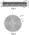
- an exemplary repositionable mounting material 100 comprises a mounting material 160 having first and second major surfaces 170, 172.
- Mounting material 160 comprises inorganic fibers 130, optional intumescent filler 140, and optional binder 145 (not shown). If present, optional binder 145 is distributed throughout mounting material 160 and strengthens the mounting material 160 by binding the various components of mounting material 160 together.
- Layer of repositionable pressure-sensitive adhesive 110 which does not extend throughout the thickness of mounting material 160, is inwardly disposed along at least a portion of first major surface 170, but does not extend through mounting material 160 to second major surface 172.
- Layer of repositionable pressure-sensitive adhesive 110 comprises adhesive microspheres 120 and binder particles 122.
- Adhesive microspheres 120 have a particle size distribution with at least one mode, each of which has a D50 of at least 30 micrometers.
- Binder particles 122 have a second particle size distribution with at least one mode, wherein each mode has a D50 that is less than 10 micrometers, and wherein at least one of the at least one modes has a D50 below one micrometer.
- Repositionable mounting material 100 is repositionably adherable to a monolith (for example, a cordierite monolith) adapted for use in a pollution control device.
- layer of repositionable pressure-sensitive adhesive 110 is releasably adhered to optional release liner 150.
- an exemplary repositionable mounting material 200 may be provided as a roll with layer of repositionable pressure-sensitive adhesive 210 releasably adhered to second major surface 272. Stacks of repositionable mounting material are also encompassed by the present invention.
- aspects of the present invention are particularly applicable to mounting materials having a relatively low degree of structural cohesiveness such as, for example, mounting materials having a maximum tensile strength of less than 200, 100, 75, or even less than 50 kiloPascals (kPa).
- the mounting material comprises inorganic fibers that are sufficiently entangled and/or bonded together to form a cohesive fiber web.
- the fibers may be entangled by a mechanical process (for example, needletacking) and/or bonded together using a binder (for example, organic binder, inorganic binder, or a combination thereof).
- the mounting material may also include organic fibers, although typically included in minor amounts, if at all.
- the mounting material has sufficient flexibility and resiliency to enable it to be wound around a monolith and used in a pollution control device.
- Useful inorganic fibers include for example, fiberglass, ceramic fibers, non-oxide inorganic fibers such as stainless steel fibers or boron fibers, and mixtures thereof.
- Useful ceramic fibers include, for example, aluminoborosilicate fibers, aluminosilicate fibers, alumina fibers, heat-treated versions thereof, and mixtures thereof.
- suitable aluminoborosilicate fibers include those commercially available under the trade designations "NEXTEL 312 CERAMIC FIBERS", “NEXTEL 440 CERAMIC FIBERS”, and “NEXTEL 550 CERAMIC FIBERS” from 3M Company, St. Paul, Minnesota.
- aluminosilicate fibers examples include those available under the trade designations "FIBERFRAX” 7000M from Unifrax Corp., Niagara Falls, New York, “CERAFIBER” from Thermal Ceramics, Augusta, Georgia; and "SNSC Type 1260 D1" from Nippon Steel Chemical Company, Tokyo, Japan.
- suitable commercially available alumina fibers include polycrystalline alumina fibers available from Saffil, Widnes, England under the trade designation "SAFFIL”.
- SAFFIL trade designation
- Suitable ceramic fibers are also disclosed in U. S. Pat. Nos. 3,795,524 (Sowman ) and 4,047,965 (Karst et al. ).
- suitable inorganic fibers include: quartz fibers, amorphous and crystalline fibers of high silica content, alumina fibers and high alumina fibers, amorphous and crystalline alumina-silica fibers, oxide and non-oxide fibers, metallic fibers, fibers formed by blowing, spinning and pulling from a melt, sol-gel formed fibers, fibers formed from organic precursors, glass fibers, leached glass fibers, and other fibers of a substantially inorganic composition.
- Suitable inorganic fibers may also comprise a surface coating or a sizing of organic and inorganic material. Suitable inorganic fibers may obviously be used alone or in combination with other suitable inorganic fibers.
- the mounting material may contain less than 75, 50, or even less than 40 percent by weight, or less, of shot based on the total dry weight of the mounting material.
- Suitable organic binders for the mounting material are known in the art and include polymers and elastomers in the latex form (for example, natural rubber latexes, styrenebutadiene latexes, butadiene-acrylonitrile latexes, and latexes of acrylate and methacrylate polymers and copolymers).
- organic binders are flocculated onto the fibers of the web using a flocculating agent, especially during wet laid manufacturing processes.
- Suitable inorganic binders are known in the art for such use and include tetrasilicic fluorine mica, in either the water-swelling non-exchanged form or after flocculation as the exchanged salt with a divalent or polyvalent cation, and bentonite.
- the mounting material may comprise one or more intumescent materials (which may be unexpanded, partially expanded, expanded, or a mixture thereof), typically, depending on the desired end use.
- intumescent materials which may be unexpanded, partially expanded, expanded, or a mixture thereof
- intumescent materials typically, depending on the desired end use.
- unexpanded vermiculite materials are suitable since they start to expand at a temperature range of from about 300 ° C to about 340 ° C. This may be useful to fill the expanding gap between an expanding metal housing and a monolith in a catalytic converter.
- expandable graphite or a mixture of expandable graphite and unexpanded vermiculite materials may be desired since expandable graphite starts to expand or intumesce at about 210 ° C.
- Treated vermiculites are also useful and typically expand at a temperature of about 290 ° C.
- useful intumescent materials include unexpanded vermiculite flakes or ore, treated unexpanded vermiculite flakes or ore, partially dehydrated vermiculite ore, expandable graphite, mixtures of expandable graphite with treated or untreated unexpanded vermiculite ore, hydrobiotite, water swellable synthetic tetrasilicic fluorine type mica (for example, as described in U. S. Pat. No. 3,001,571 (Hatch )), alkali metal silicate granules (for example, as described in U. S. Pat. No. 4,521,333 (Graham et al.
- processed expandable sodium silicate for example, insoluble sodium silicate commercially available under the trade designation "EXPANTROL” from 3M Company
- processed expandable sodium silicate for example, insoluble sodium silicate commercially available under the trade designation "EXPANTROL” from 3M Company
- An example of a commercially available expandable graphite material is that available under the trade designation "GRAFOIL Grade 338- 50" expandable graphite flake, from UCAR Carbon Co., Cleveland, Ohio.
- Treated unexpanded vermiculite flakes or ore includes unexpanded vermiculite treated by processes such as by being ion exchanged with ion exchange salts such as ammonium dihydrogen phosphate, ammonium nitrate, ammonium chloride, potassium chloride, or other suitable compounds as is known in the art.
- Factors to consider in choosing an intumescent sheet material typically include the use temperature and the type of monolith (for example, ceramic monolith or metallic monolith).
- Suitable intumescent sheet materials typically comprise unexpanded vermiculite ore (commercially available, for example, from W. R. Grace and Co., Cambridge, MA), organic binder and/or inorganic binder, ceramic fibers, and filler (for example, clay (for example, kaolin) and hollow ceramic beads or bubbles).
- U. S. Pat. No. 3,916,057 discloses intumescent sheet material comprising unexpanded vermiculite, inorganic fibrous material, and inorganic binder.
- intumescent sheet material comprising ammonium ion-treated vermiculite, inorganic fibrous material, and organic binder. Further, intumescent sheet material is commercially available, for example, from the 3M Company of St. Paul, MN, under the trade designation "INTERAM MAT MOUNT.”
- the mounting material comprises, on a dry weight basis, from 30 to 99.5 percent by weight of the inorganic fibers (for example, from 40 to 98.5 percent by weight, from 50 to 97 percent by weight, or from 60 to 97 percent by weight), from 0.5 to 9 percent by weight of an inorganic and/or organic binder (for example, from 0.5, 1.0, or 1.5 up to 3, 4, 5, 6, 7 or 8 percent by weight), and optionally up to 60 percent by weight of intumescent material, although compositions falling outside this range may also be used.
- the inorganic fibers for example, from 40 to 98.5 percent by weight, from 50 to 97 percent by weight, or from 60 to 97 percent by weight
- an inorganic and/or organic binder for example, from 0.5, 1.0, or 1.5 up to 3, 4, 5, 6, 7 or 8 percent by weight
- optionally up to 60 percent by weight of intumescent material although compositions falling outside this range may also be used.
- the percentage of inorganic fibers on a dry weight basis is typically at least 85 (for example, at least 90, 91, 92, 93, 94, or even at least 95 percent by weight, or more) percent, although lower weight percentages may also be used.
- the mounting material may optionally contain one or more inorganic fillers, inorganic binders, organic binders, organic fibers, and mixtures thereof.
- fillers examples include delaminated vermiculite, hollow glass microspheres, perlite, alumina trihydrate, calcium carbonate, and mixtures thereof. Fillers may be present in the mounting material at levels of up to 10 percent, desirably up to 25 percent, and more desirably up to 50 percent by dry weight of the mounting material.
- inorganic binders examples include micaceous particles, kaolin clay, bentonite clay, and other clay-like minerals. Inorganic binders may be present in the mounting material at levels up to 5 percent, desirably up to 25 percent, and more desirably up to 50 percent by dry weight of the mounting material.
- organic fibers for example, staple fibers or fibrillated fibers
- additives or process aides that may be included in mounting material according to the present invention include defoaming agents, surfactants, dispersants, wetting agents, salts to aid precipitation, fungicides, and bactericides.
- the mounting material is typically formulated to have physical properties suitable for in pollution control devices, although it may be formulated with different physical properties if desired.
- the mounting material has a dry basis weight in a range of from 400, 700, 1000, 1500, or even 2000 grams per square meter (gsm) up to 5000, 10000, or 15000 gsm.
- non-intumescent mounting materials typically have a dry basis weight of from 400 to 2500 gsm, more typically 1000 to 1800 gsm.
- Intumescent mounting materials typically have a dry basis weight of from 1200 to 15000 gsm, more typically 2400 to 8000 gsm.
- the mounting material may be made by any suitable technique including; for example, using air laid or wet laid techniques that are well known in the art.
- the mounting material and/or the repositionable mounting material may have any tensile strength.
- the tensile strength of mounting material and/or the repositionable mounting material at least about 50 kPa, more typically at least about 75 kPa, even more typically at least about 100 kPa..
- a slurry in water for example, typically greater than 95 percent by weight water
- a flocculent for example, typically greater than 95 percent by weight water
- Optional ingredients for example, defoaming agent, intumescent material or filler
- this process includes mixing the components and pouring the slurry onto a wire mesh or screen to remove most of the water.
- the formed sheet is then dried to form the mounting material.
- the mounting material may then be converted to desired forms such as sheets and mats.
- the process may be carried out in a step-wise, batch, and/or continuous fashion.
- higher density materials such as the optional intumescent material and higher density fillers (if used) may be added to the slurry in a smaller volume mixing vessel at a constant rate just prior to the depositing step.
- Slurries containing fillers and intumescent materials are agitated sufficiently so to prevent these particles from settling out in the mixing tank prior to pouring the slurry onto the mesh.
- Such slurries should typically be partially dewatered almost immediately after being deposited on the mesh so to prevent undesirable settling of the higher density particles.
- Vacuum dewatering of the slurries is desirable.
- Useful drying methods include wet pressing the dewatered slurries through compression or pressure rollers followed by passing the material through heated rollers and forced hot air drying as is known in the art.
- the layer of repositionable pressure-sensitive adhesive is typically prepared from components comprising adhesive microspheres and binder particles.
- the larger adhesive microspheres are primarily deposited on the outer surface of the mounting material where they are available for adhesive bonding, while the smaller binder particles typically penetrate some distance into the mounting material.
- the binder particles strengthen the mounting material near the adhesive surface such that it is less prone to damage and/or adhesive transfer during use.
- the adhesive properties of the layer can become degraded to a point where it is no longer a pressure sensitive adhesive.
- composition of the layer of repositionable adhesive for example, the relative amounts of adhesive microspheres, binder particles, and optional dispersant particles
- the particular method of its application and its application weight will typically affect adhesiveness and repositionability of the repositionable mounting material.
- these (and other) parameters may be readily adjusted according to routine experimental methods to achieve specific properties for individual mounting materials and intended applications.
- the adhesive microspheres and binder particles may be conveniently obtained and used as dispersions in a liquid vehicle.
- the liquid vehicle typically comprises water and/or volatile organic solvent (for example, a water soluble volatile organic solvent).
- the adhesive microspheres are polymeric particles that when the liquid vehicle is removed have pressure-sensitive adhesive properties.
- the adhesive microspheres may have any particle size distribution as long as at any modes that make up the distribution have a D50 of at least 30 micrometer (microns).
- the mode(s) may have a D50 in a range of from at least 30, 40, 50, or 60 micrometer (microns) up to 80, 100, 150, 200, 300, 400 or even 500 micrometer (microns), or more.
- Adhesive microspheres suitable for use in the present invention include those useful for manufacture of repositionable pressure sensitive adhesives. Typically, such adhesive microspheres are made by suspension polymerization.
- Dispersions of adhesive microspheres that can be dried to prepare repositionable pressure-sensitive adhesives are well known in the art and include, for example, those made according to procedures described in U. S. Pat. No. 5,571,617 (Cooprider et al. ); U. S. Pat. No. 5,714,237 (Cooprider et al ); U. S. Pat. No. 5,118,750 (Silver et al ); U. S. Pat. No. 5,045,569 (Delgado ); U. S. Pat. No. 5,824,748 (Kesti et al ); U. S. Pat. No. 4,786,696 (Bohnel ); and U. S. Pat. No.
- dispersions of adhesive microspheres further include a dispersion of adhesive microspheres marketed under the trade designation "CRAIGSTICK 3991 PLV” by Craig Adhesives and Coatings, Newark, NJ, and a dispersion of adhesive microspheres prepared essentially as described in Example 1 of U. S. Pat. No. 5,714,237 (Cooprider et al. ), except that 2-ethylhexyl acrylate is used in place of isooctyl acrylate.
- Dispersant particles may optionally be combined with the adhesive microspheres in a liquid vehicle, generally in small amounts, to reduce settling of the adhesive microspheres.
- the respective total volume ratio of the adhesive microspheres to the dispersant particles may be 95:5 or higher.
- Suitable dispersant particles include any polymeric stabilizer that effectively provides sufficient stabilization of the adhesive particles and prevents agglomeration within a suspension polymerization process is useful in the present invention.
- dispersant particles include salts of polyacrylic acids of greater than 5000 molecular weight average (for example, ammonium, sodium, lithium and potassium salts), carboxy-modified poly(acrylamides), copolymers of acrylic acid and dimethylaminoethyl methacrylate, polymeric quaternary amines, a quaternized poly(N-vinylpyrollidone) copolymer, and cellulosics (including quaternized amine substituted cellulosics and carboxy-modified cellulosics).
- salts of polyacrylic acids of greater than 5000 molecular weight average for example, ammonium, sodium, lithium and potassium salts
- carboxy-modified poly(acrylamides) copolymers of acrylic acid and dimethylaminoethyl methacrylate
- polymeric quaternary amines polymeric quaternary amines
- a quaternized poly(N-vinylpyrollidone) copolymer a
- the binder particles may have any particle size (for example, a particle size in a range of from 0.01, 0.1, 0.3, 0.5 or 1 micrometer up to 5, 10, or 20 micrometers, or more).
- Generally useful binder particles include those having a particle size distribution wherein all mode(s) have a D50 of less than one micrometer (micron).
- the mode(s) may have a D50 in a range of from at least 0.01, 0.05, 0.1, 0.2, or 0.3 micrometer (microns) up to 0.4, 0.5, 0.6, even 0.7 micrometer (microns), or more.
- the binder particles are made by emulsion polymerization.
- Useful binder particles include, for example, polymers and elastomers in the latex form (for example, natural rubber latexes, styrenebutadiene latexes, butadiene-acrylonitrile latexes, polyvinyl acetate latexes, polyvinyl acetate copolymer latexes, vinyl acetate - ethylene copolymers, and latexes of acrylate and methacrylate polymers and copolymers).
- polymers and elastomers in the latex form for example, natural rubber latexes, styrenebutadiene latexes, butadiene-acrylonitrile latexes, polyvinyl acetate latexes, polyvinyl acetate copolymer latexes, vinyl acetate - ethylene copolymers, and latexes of acrylate and methacrylate polymers and copolymers).
- binder particles examples include: an ethyl vinyl acetate polymer available under the trade designation "AIRFLEX 600BP” from Air Products, Allentown, PA; an acrylic polymer, available under the trade designation “FLEXCRYL SP-38” from Air Products; an acrylic polymer available under the trade designation “RHOPLEX HA-8” from Rohm and Haas, Philadelphia, PA; an acrylic polymer available under the trade designation “CARBOTAC 26146” from Noveon, Cleveland, OH; an acrylic polymer available under the trade designation “HYCAR 26410” from Noveon; and a styrene butadiene polymer available under the trade designation "STYROFAN ND-593" from BASF Corp., Florham Park, NJ.
- the binder particles may comprise a pressure-sensitive adhesive.
- the adhesive microspheres and binder particles may be present in any suitable weight ratio, typically in a respective ratio of from at least 30:70, or 40:60 up to 60:40, or 70:30. Ratios outside these ranges may be useful in some embodiments, but they tend to be either insufficiently tacky to adhere well to a monolith or so tacky that they cannot be removed from a monolith without adhesive transfer or damage to the mounting material.
- the layer of repositionable pressure-sensitive adhesive may be prepared by any suitable method.
- it may be prepared by coating the mounting material with dispersion containing adhesive microspheres and binder particles in a liquid vehicle.
- suitable coating methods include roll coating, spraying, dipping, and pad coating.
- the pressure-sensitive microsphere adhesive microspheres and the binder particles may be separately applied (for example, as two dispersions in respective liquid vehicles) to the mounting material, in any sequence.
- the layer of repositionable pressure-sensitive adhesive may be of any coating weight sufficient to impart repositionable pressure-sensitive adhesive properties.
- the layer of repositionable pressure-sensitive adhesive may be continuous or discontinuous (for example, stripes and/or dots), and may cover all or only a portion of one major surface of the mounting material. In certain embodiments, the layer of repositionable pressure-sensitive adhesive covers all or only a portion of opposed major surfaces of the mounting material. In certain embodiments, the layer of repositionable pressure-sensitive adhesive may be used to attach two or more layers of repositionable mounting material together.
- the layer of repositionable pressure-sensitive adhesive may optionally contain one or more additives such as, for example, tackifier(s), colorant(s) (for example, dyes and/or pigments), flame retardant(s), and smoke reducing agent(s).
- additives such as, for example, tackifier(s), colorant(s) (for example, dyes and/or pigments), flame retardant(s), and smoke reducing agent(s).
- Repositionable mounting material may have any dimension and/or thickness.
- the thickness of the repositionable mounting material, and likewise the mounting material is typically in a range of from 0.1 inch (0.3 cm), 0.15 inch (0.38 cm), or 0.2 inch (0.5 cm) up to 0.3 (0.8 cm), 0.5 (1.3 cm), 0.7 (1.8 cm) or one inch (2.5 cm), or more.
- Repositionable mounting material is useful in pollution control devices as mounting material (for example, a mounting mat) for mounting a monolith in a housing and/or for end cone insulation.
- the repositionable mounting material may be disposed between the monolith and the housing by wrapping the monolith with the repositionable mounting material (with the repositionable pressure-sensitive adhesive layer contacting the monolith) and inserting the wrapped monolith into the housing, or by wrapping the inner end cone housing with the repositionable mounting material and then welding the outer end cone housing to the inner end cone housing.
- the repositionable mounting material can be manufactured to any desired size and shape; for example, depending on specific application requirements. For example, automobile catalytic converters typically are smaller than diesel converters and generally require a correspondingly smaller mounting mat. Mounting mats can be stacked so that more than one layer of mat is wrapped around a monolith. Typically, the thickness of each intumescent repositionable mounting material is in the range from about 1.5 mm to about 10 mm, although other thicknesses may be used.
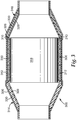
- exemplary pollution control device 305 includes housing 312 and has a generally conical inlet 314 and outlet 316 (that is, commonly referred to as end cones).
- Housing 312 which is commonly referred to as a can or a casing, is usually made of metal (for example, stainless steel).
- monolith 318 Disposed within housing 312 is monolith 318 usually made of a ceramic or metallic material, and which may include a catalyst.
- Repositionable mounting material 300 surrounds monolith 318 such that the layer of repositionable pressure-sensitive adhesive 310 is releasably adhered to monolith 318.
- Monolith 318 may be, for example, a catalytic converter element or a diesel particulate filter element.
- Inlet 314 and outlet 316 include an inner end cone housing 328 and an outer end cone housing 326.
- Insulation material 330 is positioned between the inner end cone housing 328 and the outer end cone housing 326.
- Repositionable mounting material according to the present invention may be used as insulation material 330.
- pollution control devices include, for example, catalytic converters, end cone sub-assemblies, selective catalytic reduction (SCR) units, and diesel particulate traps and filters. Further details concerning such devices may be found, for example, in U. S. Pat. Nos. 5,882,608 (Sanocki et al. ), 6,245,301 (Stroom et al. ) and RE 27,747 (Johnson ), and in U. S. Publ. Pat. Appln. No. 2006/0154040 A1 (Merry ).
- Table 1 (below) lists abbreviations and materials used in the Examples that follow: TABLE 1 ABBREVIATION DESCRIPTION SUSP1 a 40 weight percent solids pressure-sensitive microsphere adhesive obtained under the trade designation "CRAIGSTICK 3991 PLV” from Craig Adhesives and Coatings, Newark, NJ SUSP2 a 50 weight percent solids pressure-sensitive microsphere adhesive prepared essentially as described in Example 1 of U. S. Pat. No. 5,714,237 (Cooprider et al.
- Table 2 (below) lists particle size distribution information for various materials reported in Table 1.
- Specimens of a mounting material were cut to dimensions of 7 inches (20 cm) x 12 inches (30 cm).
- Dispersions of the pressure-sensitive microsphere adhesive and binder were separately mixed prior to use to ensure homogeneity.
- the particle dispersions were blended by pouring from the original container into 8-ounce (0.2-liter) glass jars, followed by stirring for one minute with a wooden tongue depressor to give a dryable composition.
- Each dryable composition was poured into a separate clean aluminum tray.
- a 1 1/4-inch (3.2-cm) diameter x 4-inch (10-cm) foam paint roller was used to apply the dryable composition to the mounting material.
- a clean roller was used for each specimen.
- the foam roller was replenished with fresh dryable composition four times per specimen.
- the specimens were coated, they were dried at 100 ° C for 15-30 minutes, whereupon the resulting dry adhesive-coated surface was protected with a sheet of silicone-coated release paper.
- the resultant coated specimens were allowed to equilibrate to room conditions (70° F (21° C), 50 percent relative humidity) for at least five days, whereupon they were weighed to determine the adhesive coating weight.
- a 0.25-inch (0.63-cm) horizontal aluminum shaft was mounted firmly at a distance of 5.5 in (13.75 cm) below and horizontally offset from the lower edge of the upper pneumatic grips of a force measurement device (available under the trade designation "MODEL 100P-12 TEST SYSTEM” available from Test Resources, Shakopee, MN).
- the specimen to be tested (1 in (2.5 cm) x 12 in (30 cm)) was circumferentially wrapped around (at least half way and with layer of repositionable pressure-sensitive adhesive against the monolith) the approximate center of a cordierite thin wall ceramic monolith (3.366 x 3.15 inch (85,5 x 80 mm), Cell: 350, Web: 5.5, Comp: EX22, Part number: 833844 7601 1000, available under the trade designation "CELCOR” from Corning, Inc., Corning, NY; 3 3/8-inch (8.4 cm) diameter x 3 1/8-inch (7.8 cm) length) with a 3/8-inch (0.93 cm) circular hole bored in the center of the circular face) and the specimen was held in place with moderate hand pressure for about 30 seconds.
- the aluminum shaft was inserted through the hole in the center of the monolith such that the assembly was firmly mounted directly below the pneumatic grips.
- the specimen was pneumatically clamped in the upper grips of the force measurement machine.
- the specimen was oriented such that the applied force was tangent to the circumference of the monolith.
- the force measurement device pulled the coated fibrous mounting material specimen off the ceramic monolith at a rate of 5 in/min minute (12.5 cm/min) for a distance of 4 inches (10 cm). The average peel force, and whether or not adhesive transfer or failure (separation) of the fiber mat, was recorded.
- a one-inch (2.5 cm) by 12-inch (30 cm) strip of 4-mil (0.01 cm) stainless steel (321 anneal stainless steel shim with a bright finish) was bonded with moderate hand pressure to a specimen to be tested (1-inch (2.5 cm) by 12-inch (30 cm) resulting in a one-inch (2.5 cm) overlap (that is, making a 23 inch strip with one end being stainless steel and one end being the support mat).
- the area of contact was one square inch (6.5 square cm).
- This construction was placed in the pneumatic clamps of a force measurement device (available under the trade designation "MODEL 100P-12 TEST SYSTEM" available from Test Resources). The specimen was placed in the lower clamp, the stainless steel in the upper clamp.
- the jaws of the force measurement device were approximately 20 inches (50 cm) apart.
- the force measurement device pulled the stainless steel strip off the specimen at a rate of five inches per minute (12.5 cm per minute) until the bond fails.
- a one-inch (2.5-cm) by 12-inch (30-cm) piece of 2 mil polypropylene strip was adhered to the adhesive-coated face of a specimen (1 inch (2.5 cm) by 12 inches (30 cm)) to be tested using moderate finger pressure such that 5 inches (13 cm) of overlap was achieved.
- the remaining 7 inches (17.5 cm) of polypropylene film was held away from the adhesive while the opposite end of the support mat was clamped into the lower jaws of the force measurement device (model 100P-12 Test System available from Test Resources, Shakopee, MN).
- the free of the polypropylene strip was carefully placed and clamped into the upper jaw of the force measurement device.
- the Jaws of the force measurement device were approximately 12 inches (30 cm) apart.
- the force measurement device was configured to pull the polypropylene film off the adhesive coated support mat at a 180° peel angle and at a rate of 5 in/min (12.5 cm/min) for a distance of 4 inches (10 cm). The average peel force, and whether or not adhesive transfer or failure (separation) of the fiber mat, was recorded.
- Coated mounting materials were prepared according to the General Procedure for Preparation of Adhesive-Coated Mounting Material. Table 3 reports results of evaluation of the adhesive-coated mounting materials by test methods described hereinabove. In Table 3 (below), an asterisk (*) indicates failure of the mounting material; and the term "ND" means not determined.
- Adhesive-coated mounting materials were prepared according to the method described in the General Procedure for Preparation of Adhesive-Coated Mounting Material (hereinabove). Table 4 reports results of evaluation of the adhesive-coated mounting materials by test methods described hereinabove. In Table 4 (below), an asterisk indicates failure of the mounting material. Examples 15, 16, 22, 23, 29, 36, and 42 do not literally fall under the range specified in the claims.
- Adhesive-coated mounting materials were prepared according to the method described in General Procedure for Preparation of Adhesive-Coated Mounting Material (hereinabove), except that additional water was added to the dryable composition in amounts as indicated. Table 5 reports results of evaluation of the adhesive-coated mounting materials by test methods described hereinabove. In Table 5 (below), an asterisk indicates failure of the mounting material.
- Adhesive-coated mounting materials were prepared according to the method described in General Procedure for Preparation of Adhesive-Coated Mounting Material (hereinabove), except that in Examples 47-48 the dispersion of adhesive microspheres and the dispersion of binder particles were applied in separate steps as reported in Table 6 with drying at 100 ° C for 15-30 minutes for each applied dispersion. Table 6 (below), also reports results of evaluation of the adhesive-coated mounting materials.
Claims (15)
- Repositionierbares Befestigungsmaterial (100, 200, 300), umfassend:ein Befestigungsmaterial (160), das erste und zweite gegenüberliegende Hauptoberflächen (170; 172, 272) aufweist und anorganische Fasern (130) umfasst; undeine Schicht aus repositionierbarem Haftkleber (110, 210, 310), der entlang mindestens eines Abschnitts der ersten Hauptoberfläche (170) einwärts angeordnet ist, wobei die Schicht aus repositionierbarem Haftkleber (110, 210, 310) umfasst:Klebermikrokügelchen (120), die eine erste Teilchengrößenverteilung mit mindestens einem ersten Modus aufweisen, von denen jeder einen D50 von mindestens 30 Mikrometern aufweist, wobei D50 auf den Teilchendurchmesser Bezug nimmt, wobei 50 Volumenprozent der Teilchen in der Verteilung einen kleineren Teilchendurchmesser aufweisen; undBindemittelteilchen (122), wobei die Bindemittelteilchen (122) eine zweite Teilchengrößenverteilung mit mindestens einem zweiten Modus aufweisen, von denen jeder einen D50 von weniger als 10 Mikrometern aufweist, und wobei mindestens einer der mindestens einen zweiten Modi einen D50 von weniger als einem Mikrometer aufweist;wobei die Klebermikrokügelchen und Bindemittelteilchen in einem Gewichtsverhältnis von 30:70 bis 70:30 vorhanden sind;wobei das repositionierbare Befestigungsmaterial repositionierbar an einen Monolithen geklebt werden kann, der zur Verwendung in einer Emissionsschutzvorrichtung geeignet ist, und wobei ein Referenzbefestigungsmaterial, das identisch zu dem repositionierbaren Befestigungsmaterial hergestellt ist, nur ohne die Bindemittelteilchen, nicht repositionierbar an den Monolithen geklebt werden kann.
- Repositionierbares Befestigungsmaterial (100, 200, 300) nach Anspruch 1, wobei die Schicht aus repositionierbarem Haftkleber (110, 210, 310) ferner Dispergiermittelteilchen umfasst, die eine dritte Größenverteilung mit mindestens einem dritten Modus aufweisen, von denen jeder einen D50 von mehr als einem Mikrometer und weniger als 30 Mikrometern aufweist, und wobei, bezogen auf das Volumen, die Klebermikrokügelchen (120) und Dispergiermittelteilchen in einem jeweiligen Verhältnis von mindestens 95:5 vorhanden sind.
- Repositionierbares Befestigungsmaterial (100, 200, 300) nach Anspruch 2, wobei, bezogen auf das Gewicht, die Klebermikrokügelchen (120) 15 bis 80 Prozent des Gesamtgewichts der Klebermikrokügelchen (120), Bindemittelteilchen (122) und Dispergiermittelteilchen zusammen umfassen.
- Repositionierbares Befestigungsmaterial (100, 200, 300) nach einem der Ansprüche 1 bis 3, wobei mindestens ein Teil der anorganischen Fasern (130) durch ein Bindemittel (145) aneinander gebunden ist.
- Repositionierbares Befestigungsmaterial (100, 200, 300) nach einem der Ansprüche 1 bis 4, wobei das Befestigungsmaterial (160) in trockenem Zustand ein Flächengewicht von 0,4 bis 15 Kilogramm pro Quadratmeter aufweist.
- Repositionierbares Befestigungsmaterial (100, 200, 300) nach einem der Ansprüche 1 bis 5, wobei das Befestigungsmaterial (160) ferner ein nicht-expandiertes Intumeszenzmaterial umfasst.
- Repositionierbares Befestigungsmaterial (100, 200, 300) nach Anspruch 1 oder 6, wobei jeder der mindestens einen ersten Modi der ersten Teilchengrößenverteilung einen D50 von mindestens 45 Mikrometer aufweist.
- Repositionierbares Befestigungsmaterial (100, 200, 300) nach einem der Ansprüche 1 bis 7, wobei jeder der mindestens einen zweiten Modi der zweiten Teilchengrößenverteilung einen D50 in einem Bereich von 0,05 bis 0,3 Mikrometer aufweist.
- Repositionierbares Befestigungsmaterial (100, 200, 300) nach einem der Ansprüche 1 bis 8, wobei sich, im Durchschnitt, die Bindemittelteilchen (122) weiter entfernt von der Hauptoberfläche befinden als die Klebermikrokügelchen (120).
- Verwendung des repositionierbaren Befestigungsmaterials (100, 200, 300) nach einem der Ansprüche 1 bis 9 in einer Emissionsschutzvorrichtung (305).
- Emissionsschutzvorrichtung (305), umfassend:ein Gehäuse (312);ein in dem Gehäuse angeordnetes Emissionsschutzelement; unddas repositionierbare Befestigungsmaterial (100, 200, 300) nach einem der Ansprüche 1 bis 9, das benachbart zum oder in dem Gehäuse (312) angeordnet ist.
- Verfahren zum Herstellen einer Emissionsschutzvorrichtung (305), wobei das Verfahren umfasst:
Anordnen des repositionierbaren Befestigungsmaterials (100, 200, 300) nach einem der Ansprüche 1 bis 9 benachbart zu oder in einem Gehäuse (312), das ein in dem Gehäuse (312) angeordnetes Emissionsschutzelement aufweist. - Verfahren zum Herstellen eines repositionierbaren Befestigungsmaterials (100, 200, 300), wobei das Verfahren umfasst:Bereitstellen eines Befestigungsmaterials (160), das erste und zweite Hauptoberflächen (170; 172, 272) aufweist und gebundene anorganische Fasern (130) umfasst; undAufbringen einer trockenbaren Zusammensetzung auf mindestens einen Abschnitt der Hauptoberfläche des Befestigungsmaterials (160), wobei die trockenbare Zusammensetzung umfasst:Klebermikrokügelchen (120), die eine erste Teilchengrößenverteilung mit mindestens einem ersten Modus aufweisen, von denen jeder einen D50 von mindestens 30 Mikrometern aufweist, wobei D50 auf den Teilchendurchmesser Bezug nimmt, wobei 50 Volumenprozent der Teilchen in der Verteilung einen kleineren Teilchendurchmesser aufweisen; undBindemittelteilchen (122), wobei die Bindemittelteilchen (122) eine zweite Teilchengrößenverteilung mit mindestens einem zweiten Modus aufweisen, von denen jeder einen D50 von weniger als 10 Mikrometern aufweist, und wobei mindestens einer der mindestens einen zweiten Modi einen D50 von weniger als einem Mikrometer aufweist; undmindestens teilweises Trocknen der trockenbaren Zusammensetzung, um eine Schicht aus repositionierbarem Haftkleber (110, 210, 310) bereitzustellen, der entlang mindestens eines Abschnitts der ersten Hauptoberfläche (170) einwärts angeordnet ist,wobei die Klebermikrokügelchen und Bindemittelteilchen in einem Gewichtsverhältnis von 30:70 bis 70:30 vorhanden sind;wobei das repositionierbare Befestigungsmaterial repositionierbar an einen Monolithen geklebt werden kann, der zur Verwendung in einer Emissionsschutzvorrichtung geeignet ist, und wobei ein Referenzbefestigungsmaterial, das identisch zu dem repositionierbaren Befestigungsmaterial hergestellt ist, nur ohne die Bindemittelteilchen, nicht repositionierbar an den Monolithen geklebt werden kann.
- Verfahren zum Herstellen eines repositionierbaren Befestigungsmaterials (100, 200, 300), wobei das Verfahren umfasst:Bereitstellen eines Befestigungsmaterials (160), das eine Hauptoberfläche aufweist und gebundene anorganische Fasern (130) umfasst; undAufbringen einer ersten trockenbaren Zusammensetzung auf mindestens einen Abschnitt der Hauptoberfläche des Befestigungsmaterials (160), wobei die erste trockenbare Zusammensetzung Klebermikrokügelchen (120) umfasst, die eine erste Teilchengrößenverteilung mit mindestens einem Modus aufweisen, von denen jeder einen D50 von mindestens 30 Mikrometern aufweist, wobei D50 auf den Teilchendurchmesser Bezug nimmt, wobei 50 Volumenprozent der Teilchen in der Verteilung einen kleineren Teilchendurchmesser aufweisen;Aufbringen einer zweiten trockenbaren Zusammensetzung, die Bindemittelteilchen (122) umfasst, wobei die Bindemittelteilchen (122) eine zweite Teilchengrößenverteilung mit mindestens einem zweiten Modus aufweisen, von denen jeder einen D50 von weniger als 10 Mikrometern aufweist, und wobei mindestens einer der mindestens einen zweiten Modi einen D50 von weniger als einem Mikrometer aufweist, auf mindestens einem Abschnitt der Hauptoberfläche des Befestigungsmaterials (160); undmindestens teilweises Trocknen der ersten und zweiten trockenbaren Zusammensetzungen, um eine Schicht aus repositionierbarem Haftkleber (110, 210, 310) bereitzustellen, der entlang mindestens eines Abschnitts der Hauptoberfläche einwärts angeordnet ist, wobei das repositionierbare Befestigungsmaterial repositionierbar an einen Monolithen geklebt werden kann, der zur Verwendung in einer Emissionsschutzvorrichtung (305) geeignet ist;wobei die Klebermikrokügelchen und Bindemittelteilchen in einem Gewichtsverhältnis von 30:70 bis 70:30 vorhanden sind.
- Verfahren nach Anspruch 13 oder 14, wobei sich, im Durchschnitt, die Bindemittelteilchen (122) weiter entfernt von der Hauptoberfläche befinden als die Klebermikrokügelchen (120).
Applications Claiming Priority (2)
| Application Number | Priority Date | Filing Date | Title |
|---|---|---|---|
| US94367407P | 2007-06-13 | 2007-06-13 | |
| PCT/US2008/061746 WO2008156918A1 (en) | 2007-06-13 | 2008-04-28 | Repositionable mounting material, pollution control device, and methods of making the same |
Publications (2)
| Publication Number | Publication Date |
|---|---|
| EP2162505A1 EP2162505A1 (de) | 2010-03-17 |
| EP2162505B1 true EP2162505B1 (de) | 2019-06-05 |
Family
ID=39650964
Family Applications (1)
| Application Number | Title | Priority Date | Filing Date |
|---|---|---|---|
| EP08769210.9A Active EP2162505B1 (de) | 2007-06-13 | 2008-04-28 | Repositionierbares montiermaterial, schadstoffminderungsvorrichtung sowie verfahren zu deren herstellung |
Country Status (9)
| Country | Link |
|---|---|
| US (1) | US8178052B2 (de) |
| EP (1) | EP2162505B1 (de) |
| JP (1) | JP2010529368A (de) |
| KR (1) | KR101502641B1 (de) |
| CN (1) | CN101755024B (de) |
| BR (1) | BRPI0812559B1 (de) |
| MX (1) | MX2009013600A (de) |
| WO (1) | WO2008156918A1 (de) |
| ZA (1) | ZA201000229B (de) |
Families Citing this family (11)
| Publication number | Priority date | Publication date | Assignee | Title |
|---|---|---|---|---|
| US8617475B2 (en) | 2007-06-13 | 2013-12-31 | 3M Innovative Properties Company | Erosion resistant mounting material and method of making and using the same |
| CN101772626A (zh) | 2007-06-13 | 2010-07-07 | 3M创新有限公司 | 可固定安装材料及其制造和使用方法 |
| GB0906837D0 (en) * | 2009-04-21 | 2009-06-03 | Saffil Automotive Ltd | Mats |
| CA2849367A1 (en) * | 2011-09-22 | 2013-03-28 | 3M Innovative Properties Company | Thermally insulated components for exhaust systems |
| JP6006087B2 (ja) | 2012-11-05 | 2016-10-12 | スリーエム イノベイティブ プロパティズ カンパニー | 熱硬化性接着剤、熱硬化性接着剤を用いた自動車用部材およびその製造方法 |
| US8968853B2 (en) | 2012-11-07 | 2015-03-03 | Firestone Building Products Company, Llc | Pressure-sensitive adhesives including expandable graphite |
| US9925640B2 (en) * | 2013-08-26 | 2018-03-27 | Rayzist Photomask, Inc. | Memorial creation process including ordering software and engraving |
| US9844925B2 (en) * | 2013-08-26 | 2017-12-19 | Rayzist Photomask, Inc. | Photoresist film with adhesive layer and microspheres |
| EP3034825B1 (de) * | 2014-12-18 | 2017-09-27 | 3M Innovative Properties Company | Lagermatte für eine Abgasverarbeitungsvorrichtung |
| WO2016136258A1 (ja) * | 2015-02-25 | 2016-09-01 | ニチアス株式会社 | 保持材、その製造方法及びそれを用いた気体処理装置 |
| EP3141648B1 (de) * | 2015-09-08 | 2018-07-18 | 3M Innovative Properties Company | Montageelement zum umwickeln und zur montage eines verschmutzungskontrollelements |
Family Cites Families (33)
| Publication number | Priority date | Publication date | Assignee | Title |
|---|---|---|---|---|
| US3444925A (en) | 1957-05-07 | 1969-05-20 | Minnesota Mining & Mfg | Structural articles and method of making |
| CA637172A (en) | 1957-08-05 | 1962-02-27 | A. Hatch Robert | Synthetic mica, mica products and method of making |
| US3795524A (en) | 1971-03-01 | 1974-03-05 | Minnesota Mining & Mfg | Aluminum borate and aluminum borosilicate articles |
| US3857731A (en) | 1973-04-06 | 1974-12-31 | Minnesota Mining & Mfg | Acrylate microsphere-surfaced sheet material |
| US3916057A (en) | 1973-08-31 | 1975-10-28 | Minnesota Mining & Mfg | Intumescent sheet material |
| US4047965A (en) | 1976-05-04 | 1977-09-13 | Minnesota Mining And Manufacturing Company | Non-frangible alumina-silica fibers |
| US4305992A (en) | 1979-11-28 | 1981-12-15 | Minnesota Mining And Manufacturing Company | Intumescent sheet material |
| US4521333A (en) | 1983-06-20 | 1985-06-04 | Minnesota Mining And Manufacturing Company | Intumescent silicates having improved stability |
| DE3514150C1 (de) | 1985-04-19 | 1986-04-10 | LEISTRITZ Maschinenfabrik GmbH, 8500 Nürnberg | Katalytische Abgasentgiftungsvorrichtung mit stabilisierter Federmatte |
| US4786696A (en) | 1987-02-06 | 1988-11-22 | Minnesota Mining And Manufacturing Company | Process for the preparation of tacky polymeric microspheres |
| US5045569A (en) | 1988-11-30 | 1991-09-03 | Minnesota Mining And Manufacturing Company | Hollow acrylate polymer microspheres |
| US4999168A (en) | 1989-05-01 | 1991-03-12 | The Carborundum Company | Crack resistant intumescent sheet material |
| US5118750A (en) | 1990-04-20 | 1992-06-02 | Minnesota Mining And Manufacturing Company | Pressure-sensitive adhesive comprising solid tacky microspheres and macromonomer-containing binder copolymer |
| US5571617A (en) | 1993-04-23 | 1996-11-05 | Minnesota Mining And Manufacturing Company | Pressure sensitive adhesive comprising tacky surface active microspheres |
| US5681612A (en) * | 1993-06-17 | 1997-10-28 | Minnesota Mining And Manufacturing Company | Coated abrasives and methods of preparation |
| US6245301B1 (en) * | 1993-08-20 | 2001-06-12 | 3M Innovative Properties Company | Catalytic converter and diesel particulate filter |
| US5736109A (en) | 1995-06-30 | 1998-04-07 | Minnesota Mining And Manufacturing Company | Intumescent sheet material and paste with organic binder |
| US5853675A (en) | 1995-06-30 | 1998-12-29 | Minnesota Mining And Manufacturing Company | Composite mounting system |
| US5696199A (en) | 1995-12-07 | 1997-12-09 | Minnesota Mining And Manufacturing Company | Pressure-sensitive adhesive polyacrylate polymer and method of making |
| US5714237A (en) * | 1996-01-16 | 1998-02-03 | Minnesota Mining Manufacturing Company | Partially crosslinked microspheres |
| US5824748A (en) | 1996-06-03 | 1998-10-20 | Minnesota Mining And Manufacturing Company | Composite pressure sensitive adhesive microspheres |
| US5882608A (en) | 1996-06-18 | 1999-03-16 | Minnesota Mining And Manufacturing Company | Hybrid mounting system for pollution control devices |
| US5756625A (en) | 1996-10-11 | 1998-05-26 | Minnesota Mining And Manufacturing Company | Stabilized adhesive microspheres |
| US6306497B1 (en) | 1998-03-03 | 2001-10-23 | Arkwright Incorporated | Pressure-sensitive adhesive articles for use on transparent imaging films |
| KR20010072915A (ko) | 1998-08-24 | 2001-07-31 | 스프레이그 로버트 월터 | 오염 제어 장치용 마운팅 재료 |
| US6759015B2 (en) | 1999-03-23 | 2004-07-06 | 3M Innovative Properties Company | Insulated mounting for a pollution control device |
| US20030109630A1 (en) | 2001-10-23 | 2003-06-12 | Smith Dawn E. | Microsphere adhesive formulations |
| EP1590556A1 (de) | 2003-01-31 | 2005-11-02 | 3M Innovative Properties Company | System zur befestigung des endkegels oder der lagerungsmatte einer abgasreinigungsvorrichtung |
| EP1495807A1 (de) | 2003-06-30 | 2005-01-12 | 3M Innovative Properties Company | Lagerungsmatte für die Lagerung eines Monoliths in einer Abgasreinigungsvorrichtung |
| US7550118B2 (en) * | 2004-04-14 | 2009-06-23 | 3M Innovative Properties Company | Multilayer mats for use in pollution control devices |
| US7645426B2 (en) | 2004-04-14 | 2010-01-12 | 3M Innovative Properties Company | Sandwich hybrid mounting mat |
| WO2006065534A1 (en) | 2004-12-13 | 2006-06-22 | 3M Innovative Properties Company | Mounting mats and pollution control devices using same |
| US8277925B2 (en) | 2006-06-01 | 2012-10-02 | Dietz Peter T | Multilayer mounting mat |
-
2008
- 2008-04-28 US US12/663,613 patent/US8178052B2/en not_active Expired - Fee Related
- 2008-04-28 CN CN200880020041XA patent/CN101755024B/zh not_active Expired - Fee Related
- 2008-04-28 BR BRPI0812559A patent/BRPI0812559B1/pt not_active IP Right Cessation
- 2008-04-28 KR KR1020107000368A patent/KR101502641B1/ko active IP Right Grant
- 2008-04-28 MX MX2009013600A patent/MX2009013600A/es active IP Right Grant
- 2008-04-28 EP EP08769210.9A patent/EP2162505B1/de active Active
- 2008-04-28 JP JP2010512226A patent/JP2010529368A/ja active Pending
- 2008-04-28 WO PCT/US2008/061746 patent/WO2008156918A1/en active Application Filing
-
2010
- 2010-01-12 ZA ZA201000229A patent/ZA201000229B/xx unknown
Non-Patent Citations (1)
| Title |
|---|
| STEVEN CORREA ET AL: "CONTROLLING PEEL ADHESION VIA HETEROGENEOUS (MICROSPHERE) PSA SYSTEMS", 3 November 2005 (2005-11-03), pages 257 - 269, XP055288928, Retrieved from the Internet <URL:https://www.pstc.org/files/public/Correa.pdf> [retrieved on 20160715] * |
Also Published As
| Publication number | Publication date |
|---|---|
| KR101502641B1 (ko) | 2015-03-13 |
| EP2162505A1 (de) | 2010-03-17 |
| MX2009013600A (es) | 2010-01-20 |
| US8178052B2 (en) | 2012-05-15 |
| US20100166619A1 (en) | 2010-07-01 |
| BRPI0812559A2 (pt) | 2015-02-10 |
| CN101755024B (zh) | 2013-12-18 |
| ZA201000229B (en) | 2010-09-29 |
| CN101755024A (zh) | 2010-06-23 |
| BRPI0812559B1 (pt) | 2018-09-04 |
| JP2010529368A (ja) | 2010-08-26 |
| KR20100019563A (ko) | 2010-02-18 |
| WO2008156918A1 (en) | 2008-12-24 |
Similar Documents
| Publication | Publication Date | Title |
|---|---|---|
| EP2162505B1 (de) | Repositionierbares montiermaterial, schadstoffminderungsvorrichtung sowie verfahren zu deren herstellung | |
| US20200224367A1 (en) | Flexible fibrous material, pollution control device, and methods of making the same | |
| JP2010529368A5 (de) | ||
| EP0835367B1 (de) | Verbundmontagesystem | |
| KR101497733B1 (ko) | 고정가능한 장착 재료 및 이의 제조 방법 및 사용 방법 | |
| US5523059A (en) | Intumescent sheet material with glass fibers | |
| EP2038523B1 (de) | Mehrschichtige montageunterlage | |
| EP2487342B1 (de) | Erosionsbeständiges Montagematerial und Verfahren zu seiner Herstellung und Verwendung | |
| MXPA97010363A (en) | Compue mounting system | |
| MXPA97010370A (en) | Intumescent leaf material with vin fibers |
Legal Events
| Date | Code | Title | Description |
|---|---|---|---|
| PUAI | Public reference made under article 153(3) epc to a published international application that has entered the european phase |
Free format text: ORIGINAL CODE: 0009012 |
|
| 17P | Request for examination filed |
Effective date: 20100107 |
|
| AK | Designated contracting states |
Kind code of ref document: A1 Designated state(s): AT BE BG CH CY CZ DE DK EE ES FI FR GB GR HR HU IE IS IT LI LT LU LV MC MT NL NO PL PT RO SE SI SK TR |
|
| AX | Request for extension of the european patent |
Extension state: AL BA MK RS |
|
| DAX | Request for extension of the european patent (deleted) | ||
| 17Q | First examination report despatched |
Effective date: 20140522 |
|
| STAA | Information on the status of an ep patent application or granted ep patent |
Free format text: STATUS: EXAMINATION IS IN PROGRESS |
|
| REG | Reference to a national code |
Ref country code: DE Ref legal event code: R079 Ref document number: 602008060279 Country of ref document: DE Free format text: PREVIOUS MAIN CLASS: C09J0007040000 Ipc: C09J0007210000 |
|
| GRAP | Despatch of communication of intention to grant a patent |
Free format text: ORIGINAL CODE: EPIDOSNIGR1 |
|
| STAA | Information on the status of an ep patent application or granted ep patent |
Free format text: STATUS: GRANT OF PATENT IS INTENDED |
|
| RIC1 | Information provided on ipc code assigned before grant |
Ipc: C09J 7/38 20180101ALI20181204BHEP Ipc: F01N 3/28 20060101ALI20181204BHEP Ipc: C09J 7/21 20180101AFI20181204BHEP |
|
| INTG | Intention to grant announced |
Effective date: 20190107 |
|
| RIC1 | Information provided on ipc code assigned before grant |
Ipc: C09J 7/21 20180101AFI20181204BHEP Ipc: C09J 7/38 20180101ALI20181204BHEP Ipc: F01N 3/28 20060101ALI20181204BHEP |
|
| GRAS | Grant fee paid |
Free format text: ORIGINAL CODE: EPIDOSNIGR3 |
|
| GRAA | (expected) grant |
Free format text: ORIGINAL CODE: 0009210 |
|
| STAA | Information on the status of an ep patent application or granted ep patent |
Free format text: STATUS: THE PATENT HAS BEEN GRANTED |
|
| AK | Designated contracting states |
Kind code of ref document: B1 Designated state(s): AT BE BG CH CY CZ DE DK EE ES FI FR GB GR HR HU IE IS IT LI LT LU LV MC MT NL NO PL PT RO SE SI SK TR |
|
| REG | Reference to a national code |
Ref country code: GB Ref legal event code: FG4D |
|
| REG | Reference to a national code |
Ref country code: CH Ref legal event code: EP |
|
| REG | Reference to a national code |
Ref country code: AT Ref legal event code: REF Ref document number: 1139952 Country of ref document: AT Kind code of ref document: T Effective date: 20190615 |
|
| REG | Reference to a national code |
Ref country code: IE Ref legal event code: FG4D |
|
| REG | Reference to a national code |
Ref country code: DE Ref legal event code: R096 Ref document number: 602008060279 Country of ref document: DE |
|
| REG | Reference to a national code |
Ref country code: NL Ref legal event code: MP Effective date: 20190605 |
|
| REG | Reference to a national code |
Ref country code: LT Ref legal event code: MG4D |
|
| PG25 | Lapsed in a contracting state [announced via postgrant information from national office to epo] |
Ref country code: FI Free format text: LAPSE BECAUSE OF FAILURE TO SUBMIT A TRANSLATION OF THE DESCRIPTION OR TO PAY THE FEE WITHIN THE PRESCRIBED TIME-LIMIT Effective date: 20190605 Ref country code: SE Free format text: LAPSE BECAUSE OF FAILURE TO SUBMIT A TRANSLATION OF THE DESCRIPTION OR TO PAY THE FEE WITHIN THE PRESCRIBED TIME-LIMIT Effective date: 20190605 Ref country code: NO Free format text: LAPSE BECAUSE OF FAILURE TO SUBMIT A TRANSLATION OF THE DESCRIPTION OR TO PAY THE FEE WITHIN THE PRESCRIBED TIME-LIMIT Effective date: 20190905 Ref country code: HR Free format text: LAPSE BECAUSE OF FAILURE TO SUBMIT A TRANSLATION OF THE DESCRIPTION OR TO PAY THE FEE WITHIN THE PRESCRIBED TIME-LIMIT Effective date: 20190605 Ref country code: LT Free format text: LAPSE BECAUSE OF FAILURE TO SUBMIT A TRANSLATION OF THE DESCRIPTION OR TO PAY THE FEE WITHIN THE PRESCRIBED TIME-LIMIT Effective date: 20190605 Ref country code: ES Free format text: LAPSE BECAUSE OF FAILURE TO SUBMIT A TRANSLATION OF THE DESCRIPTION OR TO PAY THE FEE WITHIN THE PRESCRIBED TIME-LIMIT Effective date: 20190605 |
|
| PG25 | Lapsed in a contracting state [announced via postgrant information from national office to epo] |
Ref country code: LV Free format text: LAPSE BECAUSE OF FAILURE TO SUBMIT A TRANSLATION OF THE DESCRIPTION OR TO PAY THE FEE WITHIN THE PRESCRIBED TIME-LIMIT Effective date: 20190605 Ref country code: BG Free format text: LAPSE BECAUSE OF FAILURE TO SUBMIT A TRANSLATION OF THE DESCRIPTION OR TO PAY THE FEE WITHIN THE PRESCRIBED TIME-LIMIT Effective date: 20190905 Ref country code: GR Free format text: LAPSE BECAUSE OF FAILURE TO SUBMIT A TRANSLATION OF THE DESCRIPTION OR TO PAY THE FEE WITHIN THE PRESCRIBED TIME-LIMIT Effective date: 20190906 |
|
| REG | Reference to a national code |
Ref country code: AT Ref legal event code: MK05 Ref document number: 1139952 Country of ref document: AT Kind code of ref document: T Effective date: 20190605 |
|
| PG25 | Lapsed in a contracting state [announced via postgrant information from national office to epo] |
Ref country code: PT Free format text: LAPSE BECAUSE OF FAILURE TO SUBMIT A TRANSLATION OF THE DESCRIPTION OR TO PAY THE FEE WITHIN THE PRESCRIBED TIME-LIMIT Effective date: 20191007 Ref country code: SK Free format text: LAPSE BECAUSE OF FAILURE TO SUBMIT A TRANSLATION OF THE DESCRIPTION OR TO PAY THE FEE WITHIN THE PRESCRIBED TIME-LIMIT Effective date: 20190605 Ref country code: EE Free format text: LAPSE BECAUSE OF FAILURE TO SUBMIT A TRANSLATION OF THE DESCRIPTION OR TO PAY THE FEE WITHIN THE PRESCRIBED TIME-LIMIT Effective date: 20190605 Ref country code: AT Free format text: LAPSE BECAUSE OF FAILURE TO SUBMIT A TRANSLATION OF THE DESCRIPTION OR TO PAY THE FEE WITHIN THE PRESCRIBED TIME-LIMIT Effective date: 20190605 Ref country code: RO Free format text: LAPSE BECAUSE OF FAILURE TO SUBMIT A TRANSLATION OF THE DESCRIPTION OR TO PAY THE FEE WITHIN THE PRESCRIBED TIME-LIMIT Effective date: 20190605 Ref country code: NL Free format text: LAPSE BECAUSE OF FAILURE TO SUBMIT A TRANSLATION OF THE DESCRIPTION OR TO PAY THE FEE WITHIN THE PRESCRIBED TIME-LIMIT Effective date: 20190605 Ref country code: CZ Free format text: LAPSE BECAUSE OF FAILURE TO SUBMIT A TRANSLATION OF THE DESCRIPTION OR TO PAY THE FEE WITHIN THE PRESCRIBED TIME-LIMIT Effective date: 20190605 |
|
| PG25 | Lapsed in a contracting state [announced via postgrant information from national office to epo] |
Ref country code: IT Free format text: LAPSE BECAUSE OF FAILURE TO SUBMIT A TRANSLATION OF THE DESCRIPTION OR TO PAY THE FEE WITHIN THE PRESCRIBED TIME-LIMIT Effective date: 20190605 Ref country code: IS Free format text: LAPSE BECAUSE OF FAILURE TO SUBMIT A TRANSLATION OF THE DESCRIPTION OR TO PAY THE FEE WITHIN THE PRESCRIBED TIME-LIMIT Effective date: 20191005 |
|
| REG | Reference to a national code |
Ref country code: DE Ref legal event code: R097 Ref document number: 602008060279 Country of ref document: DE |
|
| PG25 | Lapsed in a contracting state [announced via postgrant information from national office to epo] |
Ref country code: TR Free format text: LAPSE BECAUSE OF FAILURE TO SUBMIT A TRANSLATION OF THE DESCRIPTION OR TO PAY THE FEE WITHIN THE PRESCRIBED TIME-LIMIT Effective date: 20190605 |
|
| PLBE | No opposition filed within time limit |
Free format text: ORIGINAL CODE: 0009261 |
|
| STAA | Information on the status of an ep patent application or granted ep patent |
Free format text: STATUS: NO OPPOSITION FILED WITHIN TIME LIMIT |
|
| PG25 | Lapsed in a contracting state [announced via postgrant information from national office to epo] |
Ref country code: PL Free format text: LAPSE BECAUSE OF FAILURE TO SUBMIT A TRANSLATION OF THE DESCRIPTION OR TO PAY THE FEE WITHIN THE PRESCRIBED TIME-LIMIT Effective date: 20190605 Ref country code: DK Free format text: LAPSE BECAUSE OF FAILURE TO SUBMIT A TRANSLATION OF THE DESCRIPTION OR TO PAY THE FEE WITHIN THE PRESCRIBED TIME-LIMIT Effective date: 20190605 |
|
| 26N | No opposition filed |
Effective date: 20200306 |
|
| PG25 | Lapsed in a contracting state [announced via postgrant information from national office to epo] |
Ref country code: SI Free format text: LAPSE BECAUSE OF FAILURE TO SUBMIT A TRANSLATION OF THE DESCRIPTION OR TO PAY THE FEE WITHIN THE PRESCRIBED TIME-LIMIT Effective date: 20190605 |
|
| REG | Reference to a national code |
Ref country code: DE Ref legal event code: R119 Ref document number: 602008060279 Country of ref document: DE |
|
| PG25 | Lapsed in a contracting state [announced via postgrant information from national office to epo] |
Ref country code: MC Free format text: LAPSE BECAUSE OF FAILURE TO SUBMIT A TRANSLATION OF THE DESCRIPTION OR TO PAY THE FEE WITHIN THE PRESCRIBED TIME-LIMIT Effective date: 20190605 |
|
| REG | Reference to a national code |
Ref country code: CH Ref legal event code: PL |
|
| PG25 | Lapsed in a contracting state [announced via postgrant information from national office to epo] |
Ref country code: DE Free format text: LAPSE BECAUSE OF NON-PAYMENT OF DUE FEES Effective date: 20201103 Ref country code: FR Free format text: LAPSE BECAUSE OF NON-PAYMENT OF DUE FEES Effective date: 20200430 Ref country code: LU Free format text: LAPSE BECAUSE OF NON-PAYMENT OF DUE FEES Effective date: 20200428 Ref country code: CH Free format text: LAPSE BECAUSE OF NON-PAYMENT OF DUE FEES Effective date: 20200430 Ref country code: LI Free format text: LAPSE BECAUSE OF NON-PAYMENT OF DUE FEES Effective date: 20200430 |
|
| REG | Reference to a national code |
Ref country code: BE Ref legal event code: MM Effective date: 20200430 |
|
| PG25 | Lapsed in a contracting state [announced via postgrant information from national office to epo] |
Ref country code: BE Free format text: LAPSE BECAUSE OF NON-PAYMENT OF DUE FEES Effective date: 20200430 |
|
| GBPC | Gb: european patent ceased through non-payment of renewal fee |
Effective date: 20200428 |
|
| PG25 | Lapsed in a contracting state [announced via postgrant information from national office to epo] |
Ref country code: IE Free format text: LAPSE BECAUSE OF NON-PAYMENT OF DUE FEES Effective date: 20200428 Ref country code: GB Free format text: LAPSE BECAUSE OF NON-PAYMENT OF DUE FEES Effective date: 20200428 |
|
| PG25 | Lapsed in a contracting state [announced via postgrant information from national office to epo] |
Ref country code: MT Free format text: LAPSE BECAUSE OF FAILURE TO SUBMIT A TRANSLATION OF THE DESCRIPTION OR TO PAY THE FEE WITHIN THE PRESCRIBED TIME-LIMIT Effective date: 20190605 Ref country code: CY Free format text: LAPSE BECAUSE OF FAILURE TO SUBMIT A TRANSLATION OF THE DESCRIPTION OR TO PAY THE FEE WITHIN THE PRESCRIBED TIME-LIMIT Effective date: 20190605 |