EP2162328B2 - Automatic parking brake with slip controller - Google Patents
Automatic parking brake with slip controller Download PDFInfo
- Publication number
- EP2162328B2 EP2162328B2 EP08718041.0A EP08718041A EP2162328B2 EP 2162328 B2 EP2162328 B2 EP 2162328B2 EP 08718041 A EP08718041 A EP 08718041A EP 2162328 B2 EP2162328 B2 EP 2162328B2
- Authority
- EP
- European Patent Office
- Prior art keywords
- wheel
- slip
- parking brake
- brake
- threshold value
- Prior art date
- Legal status (The legal status is an assumption and is not a legal conclusion. Google has not performed a legal analysis and makes no representation as to the accuracy of the status listed.)
- Active
Links
Images

Classifications
-
- B—PERFORMING OPERATIONS; TRANSPORTING
- B60—VEHICLES IN GENERAL
- B60T—VEHICLE BRAKE CONTROL SYSTEMS OR PARTS THEREOF; BRAKE CONTROL SYSTEMS OR PARTS THEREOF, IN GENERAL; ARRANGEMENT OF BRAKING ELEMENTS ON VEHICLES IN GENERAL; PORTABLE DEVICES FOR PREVENTING UNWANTED MOVEMENT OF VEHICLES; VEHICLE MODIFICATIONS TO FACILITATE COOLING OF BRAKES
- B60T8/00—Arrangements for adjusting wheel-braking force to meet varying vehicular or ground-surface conditions, e.g. limiting or varying distribution of braking force
- B60T8/17—Using electrical or electronic regulation means to control braking
- B60T8/176—Brake regulation specially adapted to prevent excessive wheel slip during vehicle deceleration, e.g. ABS
- B60T8/1761—Brake regulation specially adapted to prevent excessive wheel slip during vehicle deceleration, e.g. ABS responsive to wheel or brake dynamics, e.g. wheel slip, wheel acceleration or rate of change of brake fluid pressure
- B60T8/17616—Microprocessor-based systems
-
- B—PERFORMING OPERATIONS; TRANSPORTING
- B60—VEHICLES IN GENERAL
- B60T—VEHICLE BRAKE CONTROL SYSTEMS OR PARTS THEREOF; BRAKE CONTROL SYSTEMS OR PARTS THEREOF, IN GENERAL; ARRANGEMENT OF BRAKING ELEMENTS ON VEHICLES IN GENERAL; PORTABLE DEVICES FOR PREVENTING UNWANTED MOVEMENT OF VEHICLES; VEHICLE MODIFICATIONS TO FACILITATE COOLING OF BRAKES
- B60T7/00—Brake-action initiating means
- B60T7/12—Brake-action initiating means for automatic initiation; for initiation not subject to will of driver or passenger
-
- B—PERFORMING OPERATIONS; TRANSPORTING
- B60—VEHICLES IN GENERAL
- B60T—VEHICLE BRAKE CONTROL SYSTEMS OR PARTS THEREOF; BRAKE CONTROL SYSTEMS OR PARTS THEREOF, IN GENERAL; ARRANGEMENT OF BRAKING ELEMENTS ON VEHICLES IN GENERAL; PORTABLE DEVICES FOR PREVENTING UNWANTED MOVEMENT OF VEHICLES; VEHICLE MODIFICATIONS TO FACILITATE COOLING OF BRAKES
- B60T8/00—Arrangements for adjusting wheel-braking force to meet varying vehicular or ground-surface conditions, e.g. limiting or varying distribution of braking force
- B60T8/32—Arrangements for adjusting wheel-braking force to meet varying vehicular or ground-surface conditions, e.g. limiting or varying distribution of braking force responsive to a speed condition, e.g. acceleration or deceleration
Definitions
- the invention relates to an automatic parking brake for motor vehicles according to the preamble of claim 1, a method for slip control according to the preamble of claim 6, and a control device with a slip regulator according to the preamble of claim 10.
- Automatic parking brakes or parking brakes usually include an operating element, such as a button, with which the parking brake can be locked or released.
- an actuator such as a hydraulic pump or an electric motor, in order to build up braking force on the vehicle's wheels or to release the brake.
- Parking brake systems of this type are generally designed in such a way that they can be actuated by the driver both when the vehicle is stationary and while driving.
- the possibility of actuation while driving is provided in particular for the purpose of still being able to brake the vehicle in the event of a defective service brake.
- the vehicle is braked with a predetermined deceleration, for example 3 m / s 2 .
- the deceleration of the vehicle is usually regulated.
- An essential aspect of the invention is to carry out slip control on the braked wheels and to design the corresponding controller such that the wheel slip of a second wheel is taken into account in the slip control on a first wheel.
- a decision is made as to whether the braking force on the controlled (first) wheel can be increased or not. This prevents both wheels from locking at the same time or from having too much slip.
- the cornering force is therefore retained at least on one wheel.
- the other wheel considered according to the invention is preferably the wheel of the same axle which is arranged on the opposite side of the vehicle.
- the wheel slip of another wheel is determined and an increase in the braking force on the controlled (first) wheel is only permitted if the wheel slip of the other wheel is less than a predetermined threshold value.
- the threshold value can, for example, be between 3% and 5%, in particular around 4% wheel slip. This ensures that both wheels do not lock at the same time and can continue to absorb cornering force.
- the slip regulator according to the invention is preferably also designed in such a way that the braking force on the controlled wheel is only increased if the wheel slip on this wheel is less than a predetermined threshold value.
- This threshold can also be around 4%. If, on the other hand, the wheel slip is greater than the threshold value, the braking force is preferably reduced.
- the deceleration of the vehicle is also taken into account in the slip control.
- an increase in the braking force on the controlled wheel is only permitted if the amount of the deceleration of the vehicle is less than a predefined threshold value. Otherwise, the braking force is preferably left the same.
- the control is preferably started asynchronously on the left and right wheels. This means that the electric motors are controlled with a time delay. This has positive effects on the control behavior, since it reduces the risk of an oscillating system in which both wheel brakes are opened or closed synchronously.
- the slip regulator according to the invention is preferably integrated as a software algorithm in a control unit which is connected to wheel speed sensors and possibly an acceleration sensor and controls the electric motors of the parking brake as described above.
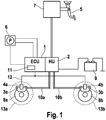
- Fig. 1 shows a block diagram of a hydraulic brake system with an automatic parking brake.
- the brake system comprises, in a known manner, a foot brake pedal 5, which interacts with a brake master cylinder (summarized in block 7) via a brake booster.
- the brake pressure generated and boosted by the driver is conducted to the wheel brakes 3, 8 via a hydraulic unit 2 (hydraulic unit), which is designed to carry out a slip control, and brake lines 10a, 10b.
- the wheel brakes 3, 8 are implemented here as disk brakes, each of which includes a brake caliper 3 and a brake disk 8.
- the automatic parking brake comprises an operating element 6 (e.g. a button) for activating or deactivating the parking brake, a control device 1 connected to the button 6, in which a parking brake algorithm with a slip regulator 11 is stored and several electric motors 4a, 4b, each are mounted on a brake caliper 3a or 3b (motor on caliper).
- the arrangement is supplied with voltage by a battery 9.
- the control unit 1 recognizes this as a parking brake request and then controls the electric motors on the brake calipers 3 in order to build up braking force and lock the brake shoes.
- the electric motors 4 are in the locked position, the brake pistons are prevented from returning to the starting position, so that the brakes remain applied.
- the control device 1 interprets this as a braking request.
- the control unit 1 controls the actuators 4 in such a way that the vehicle is braked with a predetermined deceleration, for example 3 m / s 2 . If the wheels lock up during such an emergency braking, for example due to a slippery road surface, a wheel-specific slip control is carried out on the wheels 13a or 13b, as exemplified in FIG Fig. 2 is shown.
- FIG. 13 shows a flowchart to illustrate a control strategy for the slip control of the wheels 13a, 13b during emergency braking by means of the parking brake.
- the wheels 13a, 13b are the wheels of the rear axle. The method is identical for both wheels 13a, 13b, so that only the left part of the flowchart will be discussed below.
- the actuators 4a, 4b are activated in order to brake the vehicle.
- the slip of the wheel 13a is then checked in steps 21 and 22. If the slip ⁇ 1 in step 21 is greater than, for example, 4%, the clamping force of the brakes 3a, 8a is reduced in step 27. If the ⁇ 1 is smaller than 4% and larger than 2% (N in steps 21 and 22) - this corresponds to the ideal range between 2% and 4% - there is no change in the clamping force (step 25).
- step 23 the slip ⁇ 2 of the other wheel 13b is first taken into account in step 23. This is made clear by an arrow showing the interaction between the two wheels. If the slip ⁇ 2 of the other wheel 13b is greater than 4% (N in step 23), there is no change in the clamping force (step 25), since the other wheel 13b already has a high degree of slip. If, on the other hand, the slip of the other wheel 13b is less than 4% (J in step 23), the clamping force on the wheel 13a could theoretically be increased without losing the lateral guidance. Here, however, the deceleration of the vehicle is additionally checked in step 24.
- the clamping force can be increased further in step 26. If, on the other hand, the acceleration a x is less than -2.5 m / s 2 (N in step 25), there is no change in the clamping force on the brakes 3a, 8a.
- a major advantage of this method is that at least one of the wheels has a low slip and can therefore absorb sufficient cornering force. This method is carried out analogously for the second wheel 13b, taking into account the wheel slip of the first wheel 13a.
- the control is preferably started asynchronously on the left wheel or wheel 13a or 13b.
- the activation of the corresponding actuators 4a, 4b can be delayed left / right, for example 150 ms. This has positive effects on the control behavior, since the delayed activation reduces the risk of a vibrating system in which both wheel brakes are opened or closed synchronously.
Description
Die Erfindung betrifft eine automatische Feststellbremse für Kraftfahrzeuge gemäß dem Oberbegriff des Patentanspruchs 1, ein Verfahren zur Schlupfregelung gemäß dem Oberbegriff des Patentanspruchs 6, sowie ein Steuergerät mit einem Schlupfregler gemäß dem Oberbegriff des Patentanspruchs 10.The invention relates to an automatic parking brake for motor vehicles according to the preamble of claim 1, a method for slip control according to the preamble of claim 6, and a control device with a slip regulator according to the preamble of claim 10.
Automatische Feststellbremsen bzw. Parkbremsen (APB) umfassen üblicherweise ein Bedienelement, wie z.B. einen Taster, mit dem die Feststellbremse verriegelt oder gelöst werden kann. Bei einer Betätigung des Bedienelements erkennt ein damit verbundenes Steuergerät den Feststellbremswunsch und steuert entsprechend ein Stellglied, wie z.B. eine Hydraulikpumpe oder einen Elektromotor an, um an den Rädern des Fahrzeugs Bremskraft aufzubauen oder die Bremse zu lösen.Automatic parking brakes or parking brakes (APB) usually include an operating element, such as a button, with which the parking brake can be locked or released. When the control element is actuated, a control device connected to it recognizes the parking brake request and accordingly controls an actuator, such as a hydraulic pump or an electric motor, in order to build up braking force on the vehicle's wheels or to release the brake.
Im Folgenden werden solche Systeme betrachtet, bei denen sich Elektromotoren (mit Getrieben) direkt an den Radbremsen (sog. "Motor on Caliper") befinden. Derartige Feststellbrems-Systeme sind in der Regel so ausgelegt, dass sie vom Fahrer sowohl im Stillstand des Fahrzeugs als auch während der Fahrt betätigt werden können. Die Möglichkeit einer Betätigung während des Fahrbetriebs ist insbesondere zu dem Zweck vorgesehen, das Fahrzeug im Falle einer defekten Betriebsbremse noch abbremsen zu können. In diesem Fall wird das Fahrzeug mit einer vorgegebenen Verzögerung, z.B. 3 m/s2 abgebremst. Die Verzögerung des Fahrzeugs erfolgt dabei meist geregelt.In the following, systems are considered in which electric motors (with gears) are located directly on the wheel brakes (so-called "Motor on Caliper"). Parking brake systems of this type are generally designed in such a way that they can be actuated by the driver both when the vehicle is stationary and while driving. The possibility of actuation while driving is provided in particular for the purpose of still being able to brake the vehicle in the event of a defective service brake. In this case, the vehicle is braked with a predetermined deceleration, for example 3 m / s 2 . The deceleration of the vehicle is usually regulated.
Ein Problem derartiger Feststellbrems-Systeme mit Elektromotoren besteht darin, dass die Ansprechgeschwindigkeit der mechanischen Komponenten wesentlich langsamer ist als bei einem hydraulischen Feststellbrems-System. Daraus ergibt sich eine relativ schlechte Regelbarkeit der elektromechanischen Systeme. Dies kann dazu führen, dass die gebremsten Räder während der Regelung zu lange blockieren. Ein Fahrzeug kann daher in einer kritischen Fahrsituation, wie z. B. beim Über- oder Untersteuern in einer Kurvenfahrt, die Seitenführungskraft verlieren. Das Dokument
Es ist somit die Aufgabe der vorliegenden Erfindung, eine elektromechanische Feststellbremse zu schaffen, die besser regelbar ist und dennoch eine vorgegebene Verzögerung des Fahrzeugs erreicht.It is therefore the object of the present invention to create an electromechanical parking brake which can be better regulated and which nevertheless achieves a predetermined deceleration of the vehicle.
Gelöst wird diese Aufgabe gemäß der Erfindung durch die im Patentanspruch 1, 4 und 7 angegebenen Merkmale. Weitere Ausgestaltungen der Erfindung sind Gegenstand von Unteransprüchen.This object is achieved according to the invention by the features specified in
Ein wesentlicher Aspekt der Erfindung besteht darin, an den gebremsten Rädern eine Schlupfregelung durchzuführen und den entsprechenden Regler derart auszulegen, dass bei der Schlupfregelung an einem ersten Rad der Radschlupf eines zweiten Rades berücksichtigt wird. Je nach Höhe des Radschlupfes des anderen Rades wird entschieden, ob die Bremskraft am geregelten (ersten) Rad erhöht werden kann oder nicht. Somit wird ausgeschlossen, dass beide Räder gleichzeitig blockieren bzw. einen zu hohen Schlupf aufweisen. Die Seitenführungskraft bleibt daher zumindest an einem Rad erhalten.An essential aspect of the invention is to carry out slip control on the braked wheels and to design the corresponding controller such that the wheel slip of a second wheel is taken into account in the slip control on a first wheel. Depending on the amount of wheel slip of the other wheel, a decision is made as to whether the braking force on the controlled (first) wheel can be increased or not. This prevents both wheels from locking at the same time or from having too much slip. The cornering force is therefore retained at least on one wheel.
Das erfindungsgemäß berücksichtigte andere Rad ist vorzugsweise das auf der gegenüberliegenden Fahrzeugseite angeordnete Rad derselben Achse.The other wheel considered according to the invention is preferably the wheel of the same axle which is arranged on the opposite side of the vehicle.
Gemäß einer bevorzugten Ausführungsform der Erfindung wird der Radschlupf eines anderen Rades ermittelt und eine Erhöhung der Bremskraft am geregelten (ersten) Rad nur dann zugelassen, wenn der Radschlupf des anderen Rades kleiner ist als ein vorgegebener Schwellenwert. Der Schwellenwert kann beispielsweise zwischen 3% und 5%, insbesondere bei etwa 4% Radschlupf liegen. Somit kann erreicht werden, dass beide Räder nicht gleichzeitig blockieren und weiterhin Seitenführungskraft aufnehmen können.According to a preferred embodiment of the invention, the wheel slip of another wheel is determined and an increase in the braking force on the controlled (first) wheel is only permitted if the wheel slip of the other wheel is less than a predetermined threshold value. The threshold value can, for example, be between 3% and 5%, in particular around 4% wheel slip. This ensures that both wheels do not lock at the same time and can continue to absorb cornering force.
Der erfindungsgemäße Schlupfregler ist vorzugsweise auch derart ausgelegt, dass die Bremskraft am geregelten Rad nur erhöht wird, wenn der Radschlupf an diesem Rad kleiner ist als ein vorgegebener Schwellenwert. Dieser Schwellenwert kann ebenfalls bei etwa 4% liegen. Wenn der Radschlupf dagegen größer ist als der Schwellenwert, wird die Bremskraft vorzugsweise verringert.The slip regulator according to the invention is preferably also designed in such a way that the braking force on the controlled wheel is only increased if the wheel slip on this wheel is less than a predetermined threshold value. This threshold can also be around 4%. If, on the other hand, the wheel slip is greater than the threshold value, the braking force is preferably reduced.
Gemäß einer speziellen Ausführungsform der Erfindung wird bei der Schlupfregelung ferner noch die Verzögerung des Fahrzeugs berücksichtigt. In diesem Fall wird eine Erhöhung der Bremskraft am geregelten Rad nur zugelassen, wenn die Verzögerung des Fahrzeugs betragsmäßig kleiner ist als ein vorgegebener Schwellenwert. Andernfalls wird die Bremskraft vorzugsweise gleich belassen.According to a special embodiment of the invention, the deceleration of the vehicle is also taken into account in the slip control. In this case, an increase in the braking force on the controlled wheel is only permitted if the amount of the deceleration of the vehicle is less than a predefined threshold value. Otherwise, the braking force is preferably left the same.
Nach dem Auslösen einer Bremsung wird die Regelung am linken und rechten Rad vorzugsweise asynchron gestartet. D.h., die Ansteuerung der Elektromotoren erfolgt zeitverzögert. Dies hat positive Auswirkungen auf das Regelverhalten, da sich dadurch die Gefahr eines schwingenden Systems, bei dem beide Radbremsen synchron geöffnet oder geschlossen werden, reduziert.After braking has been initiated, the control is preferably started asynchronously on the left and right wheels. This means that the electric motors are controlled with a time delay. This has positive effects on the control behavior, since it reduces the risk of an oscillating system in which both wheel brakes are opened or closed synchronously.
Der erfindungsgemäße Schlupfregler ist vorzugsweise als Software-Algorithmus in einem Steuergerät integriert, das mit Rad-Drehzahlsensoren und gegebenenfalls einem Beschleunigungssensor verbunden ist und die Elektromotoren der Feststellbremse wie vorstehend beschrieben ansteuert.The slip regulator according to the invention is preferably integrated as a software algorithm in a control unit which is connected to wheel speed sensors and possibly an acceleration sensor and controls the electric motors of the parking brake as described above.
Die Erfindung wird nachstehend anhand der beigefügten Zeichnungen beispielhaft näher erläutert. Es zeigen:
- Fig. 1
- eine schematische Darstellung einer Kfz-Bremsanlage mit einer automatischen Feststellbremse; und
- Fig. 2
- ein Flussdiagramm zur Darstellung der Regelstrategie der Schlupfregelung.
- Fig. 1
- a schematic representation of a motor vehicle brake system with an automatic parking brake; and
- Fig. 2
- a flowchart to illustrate the control strategy of the slip control.
Die automatische Feststellbremse umfasst ein Bedienelement 6 (z.B. einen Taster) zum Aktivieren bzw. Deaktivieren der Feststellbremse, ein mit dem Taster 6 verbundenes Steuergerät 1, in dem ein Feststellbrems-Algorithmus mit einem Schlupfregler 11 hinterlegt ist und mehrere Elektromotoren 4a,4b, die jeweils an einem Bremssattel 3a bzw. 3b montiert sind (Motor on Caliper). Die Anordnung wird von einer Batterie 9 mit Spannung versorgt.The automatic parking brake comprises an operating element 6 (e.g. a button) for activating or deactivating the parking brake, a control device 1 connected to the button 6, in which a parking brake algorithm with a
Um das Fahrzeug im geparkten Zustand zu sichern, betätigt der Fahrer kurz den Taster 6. Das Steuergerät 1 erkennt dies als Feststellbremswunsch und steuert daraufhin die an den Bremssätteln 3 befindlichen Elektromotoren an, um Bremskraft aufzubauen und die Bremsbacken zu verriegeln. Wenn sich die Elektromotoren 4 in der verriegelten Stellung befinden, werden die Bremskolben daran gehindert, zurück in die Ausgangsposition zu gelangen, so dass die Bremsen zugespannt bleiben.To secure the vehicle when parked, the driver briefly presses the button 6. The control unit 1 recognizes this as a parking brake request and then controls the electric motors on the brake calipers 3 in order to build up braking force and lock the brake shoes. When the
Bei einer Betätigung des Tasters 6 während der Fahrt wird dies vom Steuergerät 1 als Bremswunsch interpretiert. Das Steuergerät 1 steuert daraufhin die Aktuatoren 4 derart an, dass das Fahrzeug mit einer vorgegebenen Verzögerung, z.B. 3 m/s2 abgebremst wird. Wenn die Räder bei einer solchen Notbremsung, z.B. aufgrund einer glatten Fahrbahn, blockieren, wird eine radindividuelle Schlupfregelung an den Rädern 13a bzw. 13b durchgeführt, wie sie beispielhaft in
Sobald der Fahrer in Schritt 20 den Taster 6 betätigt hat, werden die Aktuatoren 4a, 4b angesteuert, um das Fahrzeug abzubremsen. In den Schritten 21 und 22 wird dann der Schlupf des Rades 13a überprüft. Falls der Schlupf λ1 in Schritt 21 größer ist als z.B. 4%, wird in Schritt 27 die Klemmkraft der Bremse 3a,8a verringert. Falls der λ1 kleiner als 4% und größer als 2% ist (N in Schritt 21 und 22) - dies entspricht dem idealen Bereich zwischen 2% und 4% - erfolgt keine Änderung der Klemmkraft (Schritt 25). Wenn der Schlupf λ1 dagegen kleiner ist als 2% (J in Schritt 22) und somit theoretisch die Klemmkraft an diesem Rad weiter erhöht werden könnte, wird in Schritt 23 zunächst der Schlupf λ2 des anderen Rades 13b berücksichtigt. Dies wird durch einen Pfeil, der die Wechselwirkung zwischen den beiden Rädern darstellt, verdeutlicht. Wenn der Schlupf λ2 des anderen Rades 13b größer ist als 4% (N in Schritt 23) erfolgt keine Klemmkraftänderung (Schritt 25), da das andere Rad 13b bereits hohen Schlupf aufweist. Falls der Schlupf des anderen Rades 13b dagegen kleiner ist als 4% (J in Schritt 23), könnte die Klemmkraft am Rad 13a theoretisch erhöht werden, ohne die Seitenführung zu verlieren. Hier wird jedoch in Schrit 24 noch zusätzlich die Verzögerung des Fahrzeugs überprüft. Ist die Beschleunigung ax größer als -2,5 m/s2, (also beispielsweise -1 m/s2) so kann die Klemmkraft in Schritt 26 weiter erhöht werden. Ist die Beschleunigung ax dagegen kleiner als -2,5 m/s2 (N in Schritt 25), erfolgt keine Klemmkraftänderung an der Bremse 3a,8a.As soon as the driver has actuated the button 6 in
Ein wesentlicher Vorteil dieses Verfahrens besteht darin, dass zumindest eines der Räder einen geringen Schlupf aufweist und somit ausreichend Seitenführungskraft aufnehmen kann. Dieses Verfahren wird für das zweite Rad 13b unter Berücksichtigung des Radschlupfes des ersten Rades 13a analog durchgeführt.A major advantage of this method is that at least one of the wheels has a low slip and can therefore absorb sufficient cornering force. This method is carried out analogously for the
Nach dem Auslösen der Bremsung durch Betätigung des Tasters 6 wird die Regelung am linken bzw. Rad 13a bzw. 13b vorzugsweise asynchron gestartet. Die Ansteuerung der entsprechenden Aktuatoren 4a,4b kann links/rechts beispielsweise 150 ms zeitverzögert erfolgen. Dies hat positive Auswirkungen auf das Regelverhalten, da sich durch das zeitversetzte Ansteuern die Gefahr eines schwingenden Systems, bei dem beide Radbremsen synchron geöffnet oder geschlossen werden, reduziert.After the braking has been triggered by pressing the button 6, the control is preferably started asynchronously on the left wheel or
Claims (7)
- Automatic parking brake for motor vehicles having multiple brake actuators (4a, 4b), which are electric motors (4a, 4b) arranged on the brake calliper (3a, 3b), and having an operator control element (6) for actuating the parking brake, characterized in that the brake actuators (4a, 4b) are connected to a regulator (1, 11) which can perform wheel-specific slip regulation in particular driving situations, wherein the regulator (1, 11) is configured such that, in slip regulation at a first wheel (13a), the slip (λ2) of a second wheel (13b) is taken into consideration, wherein the clamping force at the first wheel (13a) is increased only if the slip (λ2) of the second wheel (13b) is below a predefined threshold value.
- Automatic parking brake according to Claim 1, characterized in that the threshold value lies between 3% and 5%, in particular is approximately 4%.
- Automatic parking brake according to one of the preceding claims, characterized in that the second wheel (13b) is arranged on the other longitudinal side of the vehicle.
- Method for regulating the slip of the wheels (13a, 13b) of a vehicle after the initiation of a braking operation by means of an automatic, electromechanical parking brake, characterized in that, in the performing of wheel-specific slip regulation at a first wheel (13a), the wheel slip (λ2) of a second wheel (13b) is taken into consideration, wherein the clamping force at the first wheel (13a) is increased only if the wheel slip (λ2) of the second wheel (13b) is below a predefined threshold value.
- Method according to Claim 4, characterized in that the clamping force at the first wheel (13a) is increased only if the wheel slip (λ1) at said wheel is below a predefined threshold value.
- Method according to one of Claims 4 and 5, characterized in that the braking force is increased only if the deceleration (ax) of the vehicle is, in terms of magnitude, below a predefined threshold value.
- Control unit (1) having a slip regulator (11) which comprises means for performing wheel-specific slip regulation in accordance with one of the preceding method claims.
Applications Claiming Priority (2)
| Application Number | Priority Date | Filing Date | Title |
|---|---|---|---|
| DE102007022510A DE102007022510A1 (en) | 2007-05-14 | 2007-05-14 | Automatic parking brake with slip control |
| PCT/EP2008/053320 WO2008138668A1 (en) | 2007-05-14 | 2008-03-19 | Automatic parking brake with slip controller |
Publications (3)
| Publication Number | Publication Date |
|---|---|
| EP2162328A1 EP2162328A1 (en) | 2010-03-17 |
| EP2162328B1 EP2162328B1 (en) | 2018-10-31 |
| EP2162328B2 true EP2162328B2 (en) | 2021-02-10 |
Family
ID=39627816
Family Applications (1)
| Application Number | Title | Priority Date | Filing Date |
|---|---|---|---|
| EP08718041.0A Active EP2162328B2 (en) | 2007-05-14 | 2008-03-19 | Automatic parking brake with slip controller |
Country Status (5)
| Country | Link |
|---|---|
| US (1) | US8991943B2 (en) |
| EP (1) | EP2162328B2 (en) |
| JP (1) | JP5341877B2 (en) |
| DE (1) | DE102007022510A1 (en) |
| WO (1) | WO2008138668A1 (en) |
Families Citing this family (8)
| Publication number | Priority date | Publication date | Assignee | Title |
|---|---|---|---|---|
| DE102010025719A1 (en) * | 2010-06-30 | 2012-05-16 | Wabco Gmbh | Device and method for emitting a dangerous ground signal under a vehicle |
| DE102012010562B4 (en) * | 2012-05-26 | 2013-12-24 | Audi Ag | Parking brake system for a vehicle |
| DE102014226856A1 (en) * | 2014-12-22 | 2016-06-23 | Robert Bosch Gmbh | Method and device for operating a braking device, braking device |
| DE102015212109A1 (en) | 2015-06-30 | 2017-01-05 | Continental Teves Ag & Co. Ohg | Method for carrying out an emergency braking function by means of an electromechanical parking brake of a vehicle |
| DE102017208178A1 (en) * | 2017-05-16 | 2018-11-22 | Continental Teves Ag & Co. Ohg | Brake system and method for operating a brake system |
| JP6859842B2 (en) * | 2017-05-17 | 2021-04-14 | 株式会社アドヴィックス | Vehicle braking device |
| DE102018208877A1 (en) | 2018-06-06 | 2019-12-12 | Robert Bosch Gmbh | Method for operating a brake system of a motor vehicle, and control unit and brake system |
| DE102018210021A1 (en) | 2018-06-20 | 2019-12-24 | Robert Bosch Gmbh | Method for operating a brake system of a motor vehicle, and control device and brake system |
Citations (10)
| Publication number | Priority date | Publication date | Assignee | Title |
|---|---|---|---|---|
| US3918766A (en) † | 1973-04-21 | 1975-11-11 | Wabco Westinghouse Gmbh | Individual wheel anti-skid brake control system having means to prevent excessive brake pressure differences |
| US5139315A (en) † | 1991-02-28 | 1992-08-18 | General Motors Corporation | Vehicle parking brake system and method |
| DE4421565A1 (en) † | 1994-06-20 | 1995-12-21 | Teves Gmbh Alfred | Circuit arrangement for a brake system with BASR |
| WO1999038738A1 (en) † | 1998-01-31 | 1999-08-05 | Continental Teves Ag & Co. Ohg | Motor vehicle brake system with electrically controllable parking brake unit |
| US6050655A (en) † | 1997-06-02 | 2000-04-18 | Mitsubishi Denki Kabushiki Kaisha | Antiskid brake controller |
| US20020117891A1 (en) † | 1999-05-05 | 2002-08-29 | Harris Alan Leslie | Back-up braking in electro-hydraulic (EHB) braking system |
| US6502029B2 (en) † | 2001-01-03 | 2002-12-31 | Delphi Technologies, Inc. | System and method for ABS stability control |
| US6860570B2 (en) † | 2000-09-01 | 2005-03-01 | Toyota Jidosha Kabushiki Kaisha | Vehicular parking brake apparatus and control method thereof |
| US6880900B2 (en) † | 2001-05-30 | 2005-04-19 | Toyota Jidosha Kabushiki Kaisha | Brake control system and method for vehicle |
| EP1557334A2 (en) † | 2000-09-28 | 2005-07-27 | Toyota Jidosha Kabushiki Kaisha | Apparatus and Method for Vehicular Brake Control |
Family Cites Families (13)
| Publication number | Priority date | Publication date | Assignee | Title |
|---|---|---|---|---|
| DE4022671A1 (en) | 1990-07-17 | 1992-01-23 | Wabco Westinghouse Fahrzeug | ELECTRONIC BRAKE SYSTEM FOR ROAD VEHICLES |
| JP3696290B2 (en) * | 1995-04-14 | 2005-09-14 | 三菱電機株式会社 | Anti-skid control device |
| JP3592444B2 (en) * | 1996-06-11 | 2004-11-24 | 株式会社ホンダエレシス | Anti-lock brake control device for vehicles |
| GB2349676B (en) * | 1999-05-05 | 2003-04-23 | Lucas Ind Plc | Improved back-up braking in vehicle braking systems |
| US6512973B2 (en) * | 2001-01-03 | 2003-01-28 | Delphi Technologies, Inc. | System and method for ABS stability control |
| JP2004123084A (en) * | 2002-08-08 | 2004-04-22 | Asmo Co Ltd | Traction control device |
| JP2006509680A (en) * | 2002-12-13 | 2006-03-23 | コンティネンタル・テーベス・アクチエンゲゼルシヤフト・ウント・コンパニー・オッフェネ・ハンデルスゲゼルシヤフト | Adaptive brake torque adjustment method |
| US6964460B2 (en) * | 2003-12-03 | 2005-11-15 | Delphi Technologies, Inc. | Brake controller and method for controlling a brake system |
| US20070132309A1 (en) * | 2004-02-09 | 2007-06-14 | Volker Knop | Hydraulic vehicle brake |
| JP4825668B2 (en) | 2004-10-06 | 2011-11-30 | 日立オートモティブシステムズ株式会社 | Electric brake device |
| DE102005060023A1 (en) * | 2005-12-15 | 2007-06-28 | Siemens Ag | Method and device for determining a maximum coefficient of friction on a wheel of a stationary vehicle |
| JP4293215B2 (en) * | 2006-09-15 | 2009-07-08 | トヨタ自動車株式会社 | Electric parking brake system |
| JP5125609B2 (en) * | 2008-02-28 | 2013-01-23 | 株式会社アドヴィックス | Braking force distribution control device |
-
2007
- 2007-05-14 DE DE102007022510A patent/DE102007022510A1/en not_active Withdrawn
-
2008
- 2008-03-19 US US12/600,257 patent/US8991943B2/en active Active
- 2008-03-19 EP EP08718041.0A patent/EP2162328B2/en active Active
- 2008-03-19 WO PCT/EP2008/053320 patent/WO2008138668A1/en active Application Filing
- 2008-03-19 JP JP2010506874A patent/JP5341877B2/en active Active
Patent Citations (10)
| Publication number | Priority date | Publication date | Assignee | Title |
|---|---|---|---|---|
| US3918766A (en) † | 1973-04-21 | 1975-11-11 | Wabco Westinghouse Gmbh | Individual wheel anti-skid brake control system having means to prevent excessive brake pressure differences |
| US5139315A (en) † | 1991-02-28 | 1992-08-18 | General Motors Corporation | Vehicle parking brake system and method |
| DE4421565A1 (en) † | 1994-06-20 | 1995-12-21 | Teves Gmbh Alfred | Circuit arrangement for a brake system with BASR |
| US6050655A (en) † | 1997-06-02 | 2000-04-18 | Mitsubishi Denki Kabushiki Kaisha | Antiskid brake controller |
| WO1999038738A1 (en) † | 1998-01-31 | 1999-08-05 | Continental Teves Ag & Co. Ohg | Motor vehicle brake system with electrically controllable parking brake unit |
| US20020117891A1 (en) † | 1999-05-05 | 2002-08-29 | Harris Alan Leslie | Back-up braking in electro-hydraulic (EHB) braking system |
| US6860570B2 (en) † | 2000-09-01 | 2005-03-01 | Toyota Jidosha Kabushiki Kaisha | Vehicular parking brake apparatus and control method thereof |
| EP1557334A2 (en) † | 2000-09-28 | 2005-07-27 | Toyota Jidosha Kabushiki Kaisha | Apparatus and Method for Vehicular Brake Control |
| US6502029B2 (en) † | 2001-01-03 | 2002-12-31 | Delphi Technologies, Inc. | System and method for ABS stability control |
| US6880900B2 (en) † | 2001-05-30 | 2005-04-19 | Toyota Jidosha Kabushiki Kaisha | Brake control system and method for vehicle |
Also Published As
| Publication number | Publication date |
|---|---|
| US8991943B2 (en) | 2015-03-31 |
| DE102007022510A1 (en) | 2008-11-20 |
| EP2162328B1 (en) | 2018-10-31 |
| EP2162328A1 (en) | 2010-03-17 |
| WO2008138668A1 (en) | 2008-11-20 |
| US20110017554A1 (en) | 2011-01-27 |
| JP5341877B2 (en) | 2013-11-13 |
| JP2010526701A (en) | 2010-08-05 |
Similar Documents
| Publication | Publication Date | Title |
|---|---|---|
| EP3529117B2 (en) | System comprising separate control units for the actuation units of an electric parking brake | |
| EP3529118B1 (en) | System comprising separate control units for the actuation units of an electric parking brake | |
| EP2162328B2 (en) | Automatic parking brake with slip controller | |
| EP3044056B2 (en) | Driver assistance system with increased reliability and availability | |
| EP1424254B1 (en) | Method for applying an automatic braking | |
| DE102007030441B4 (en) | Brake system for a motor vehicle and method for operating a brake system of a motor vehicle | |
| EP1771324B1 (en) | Brake device for a vehicle with an electric parking brake system and corresponding control method | |
| EP2619052B1 (en) | Retaining function for a motor vehicle | |
| DE112019000906T5 (en) | Electric brake device and control device for an electric brake | |
| DE102012212329A1 (en) | Method for ensuring braking action of brake system for vehicle e.g. motor car, involves activating parking brake when determined delay size is less than deceleration value and determined slip is below slip threshold | |
| WO2016055193A1 (en) | Braking mechanism for a motor vehicle, and method for controlling the braking mechanism when different force components are combined | |
| DE602004000867T2 (en) | Device and method for operating an electric parking brake | |
| EP3867113B1 (en) | Method for decelerating a motor vehicle during emergency braking and motor vehicle | |
| DE112019003231T5 (en) | Electric brake device, electric brake control device and brake control device | |
| DE102018208877A1 (en) | Method for operating a brake system of a motor vehicle, and control unit and brake system | |
| DE102008007714B4 (en) | Method for regulating the pressure in an electronically controlled brake system and electronic brake system | |
| WO2020201212A1 (en) | Method for decelerating a motor vehicle during emergency braking with an electric motor of an electric drive of the motor vehicle and a braking torque of a service brake system of the motor vehicle, and motor vehicle | |
| EP3300974A1 (en) | Method and device for controlling a braking assembly for a vehicle, brake system and vehicle | |
| DE102014203889A1 (en) | Method for operating a brake system | |
| DE102016207284A1 (en) | An automated parking brake and method for controlling an automated parking brake following an accident of a motor vehicle | |
| WO2005007474A1 (en) | Method for controlling a brake system and brake system for a vehicle | |
| DE102018210021A1 (en) | Method for operating a brake system of a motor vehicle, and control device and brake system | |
| DE10348392B4 (en) | Safety-optimized vehicle brake system with electric parking brake system | |
| DE19614908A1 (en) | Brake system with electronic brake force distribution | |
| DE10324959A1 (en) | Operating method for a motor vehicle hybrid braking system in which at least two braking requirements are determined corresponding to a braking wish, with the two requirements making different contributions to vehicle deceleration |
Legal Events
| Date | Code | Title | Description |
|---|---|---|---|
| PUAI | Public reference made under article 153(3) epc to a published international application that has entered the european phase |
Free format text: ORIGINAL CODE: 0009012 |
|
| 17P | Request for examination filed |
Effective date: 20091214 |
|
| AK | Designated contracting states |
Kind code of ref document: A1 Designated state(s): AT BE BG CH CY CZ DE DK EE ES FI FR GB GR HR HU IE IS IT LI LT LU LV MC MT NL NO PL PT RO SE SI SK TR |
|
| AX | Request for extension of the european patent |
Extension state: AL BA MK RS |
|
| DAX | Request for extension of the european patent (deleted) | ||
| 17Q | First examination report despatched |
Effective date: 20130705 |
|
| REG | Reference to a national code |
Ref country code: DE Ref legal event code: R079 Ref document number: 502008016424 Country of ref document: DE Free format text: PREVIOUS MAIN CLASS: B60T0008176100 Ipc: B60T0007120000 |
|
| GRAP | Despatch of communication of intention to grant a patent |
Free format text: ORIGINAL CODE: EPIDOSNIGR1 |
|
| STAA | Information on the status of an ep patent application or granted ep patent |
Free format text: STATUS: GRANT OF PATENT IS INTENDED |
|
| RIC1 | Information provided on ipc code assigned before grant |
Ipc: B60T 7/12 20060101AFI20180620BHEP |
|
| INTG | Intention to grant announced |
Effective date: 20180725 |
|
| GRAS | Grant fee paid |
Free format text: ORIGINAL CODE: EPIDOSNIGR3 |
|
| GRAA | (expected) grant |
Free format text: ORIGINAL CODE: 0009210 |
|
| STAA | Information on the status of an ep patent application or granted ep patent |
Free format text: STATUS: THE PATENT HAS BEEN GRANTED |
|
| AK | Designated contracting states |
Kind code of ref document: B1 Designated state(s): AT BE BG CH CY CZ DE DK EE ES FI FR GB GR HR HU IE IS IT LI LT LU LV MC MT NL NO PL PT RO SE SI SK TR |
|
| REG | Reference to a national code |
Ref country code: CH Ref legal event code: EP Ref country code: GB Ref legal event code: FG4D Free format text: NOT ENGLISH |
|
| REG | Reference to a national code |
Ref country code: AT Ref legal event code: REF Ref document number: 1058986 Country of ref document: AT Kind code of ref document: T Effective date: 20181115 |
|
| REG | Reference to a national code |
Ref country code: DE Ref legal event code: R096 Ref document number: 502008016424 Country of ref document: DE |
|
| REG | Reference to a national code |
Ref country code: IE Ref legal event code: FG4D Free format text: LANGUAGE OF EP DOCUMENT: GERMAN |
|
| REG | Reference to a national code |
Ref country code: NL Ref legal event code: MP Effective date: 20181031 |
|
| REG | Reference to a national code |
Ref country code: LT Ref legal event code: MG4D |
|
| PG25 | Lapsed in a contracting state [announced via postgrant information from national office to epo] |
Ref country code: PL Free format text: LAPSE BECAUSE OF FAILURE TO SUBMIT A TRANSLATION OF THE DESCRIPTION OR TO PAY THE FEE WITHIN THE PRESCRIBED TIME-LIMIT Effective date: 20181031 Ref country code: HR Free format text: LAPSE BECAUSE OF FAILURE TO SUBMIT A TRANSLATION OF THE DESCRIPTION OR TO PAY THE FEE WITHIN THE PRESCRIBED TIME-LIMIT Effective date: 20181031 Ref country code: LT Free format text: LAPSE BECAUSE OF FAILURE TO SUBMIT A TRANSLATION OF THE DESCRIPTION OR TO PAY THE FEE WITHIN THE PRESCRIBED TIME-LIMIT Effective date: 20181031 Ref country code: LV Free format text: LAPSE BECAUSE OF FAILURE TO SUBMIT A TRANSLATION OF THE DESCRIPTION OR TO PAY THE FEE WITHIN THE PRESCRIBED TIME-LIMIT Effective date: 20181031 Ref country code: NO Free format text: LAPSE BECAUSE OF FAILURE TO SUBMIT A TRANSLATION OF THE DESCRIPTION OR TO PAY THE FEE WITHIN THE PRESCRIBED TIME-LIMIT Effective date: 20190131 Ref country code: IS Free format text: LAPSE BECAUSE OF FAILURE TO SUBMIT A TRANSLATION OF THE DESCRIPTION OR TO PAY THE FEE WITHIN THE PRESCRIBED TIME-LIMIT Effective date: 20190228 Ref country code: FI Free format text: LAPSE BECAUSE OF FAILURE TO SUBMIT A TRANSLATION OF THE DESCRIPTION OR TO PAY THE FEE WITHIN THE PRESCRIBED TIME-LIMIT Effective date: 20181031 Ref country code: ES Free format text: LAPSE BECAUSE OF FAILURE TO SUBMIT A TRANSLATION OF THE DESCRIPTION OR TO PAY THE FEE WITHIN THE PRESCRIBED TIME-LIMIT Effective date: 20181031 Ref country code: BG Free format text: LAPSE BECAUSE OF FAILURE TO SUBMIT A TRANSLATION OF THE DESCRIPTION OR TO PAY THE FEE WITHIN THE PRESCRIBED TIME-LIMIT Effective date: 20190131 |
|
| PG25 | Lapsed in a contracting state [announced via postgrant information from national office to epo] |
Ref country code: NL Free format text: LAPSE BECAUSE OF FAILURE TO SUBMIT A TRANSLATION OF THE DESCRIPTION OR TO PAY THE FEE WITHIN THE PRESCRIBED TIME-LIMIT Effective date: 20181031 Ref country code: GR Free format text: LAPSE BECAUSE OF FAILURE TO SUBMIT A TRANSLATION OF THE DESCRIPTION OR TO PAY THE FEE WITHIN THE PRESCRIBED TIME-LIMIT Effective date: 20190201 Ref country code: SE Free format text: LAPSE BECAUSE OF FAILURE TO SUBMIT A TRANSLATION OF THE DESCRIPTION OR TO PAY THE FEE WITHIN THE PRESCRIBED TIME-LIMIT Effective date: 20181031 Ref country code: PT Free format text: LAPSE BECAUSE OF FAILURE TO SUBMIT A TRANSLATION OF THE DESCRIPTION OR TO PAY THE FEE WITHIN THE PRESCRIBED TIME-LIMIT Effective date: 20190301 |
|
| PG25 | Lapsed in a contracting state [announced via postgrant information from national office to epo] |
Ref country code: CZ Free format text: LAPSE BECAUSE OF FAILURE TO SUBMIT A TRANSLATION OF THE DESCRIPTION OR TO PAY THE FEE WITHIN THE PRESCRIBED TIME-LIMIT Effective date: 20181031 Ref country code: DK Free format text: LAPSE BECAUSE OF FAILURE TO SUBMIT A TRANSLATION OF THE DESCRIPTION OR TO PAY THE FEE WITHIN THE PRESCRIBED TIME-LIMIT Effective date: 20181031 Ref country code: IT Free format text: LAPSE BECAUSE OF FAILURE TO SUBMIT A TRANSLATION OF THE DESCRIPTION OR TO PAY THE FEE WITHIN THE PRESCRIBED TIME-LIMIT Effective date: 20181031 |
|
| REG | Reference to a national code |
Ref country code: DE Ref legal event code: R026 Ref document number: 502008016424 Country of ref document: DE |
|
| PLBI | Opposition filed |
Free format text: ORIGINAL CODE: 0009260 |
|
| PLAX | Notice of opposition and request to file observation + time limit sent |
Free format text: ORIGINAL CODE: EPIDOSNOBS2 |
|
| PG25 | Lapsed in a contracting state [announced via postgrant information from national office to epo] |
Ref country code: RO Free format text: LAPSE BECAUSE OF FAILURE TO SUBMIT A TRANSLATION OF THE DESCRIPTION OR TO PAY THE FEE WITHIN THE PRESCRIBED TIME-LIMIT Effective date: 20181031 Ref country code: EE Free format text: LAPSE BECAUSE OF FAILURE TO SUBMIT A TRANSLATION OF THE DESCRIPTION OR TO PAY THE FEE WITHIN THE PRESCRIBED TIME-LIMIT Effective date: 20181031 Ref country code: SK Free format text: LAPSE BECAUSE OF FAILURE TO SUBMIT A TRANSLATION OF THE DESCRIPTION OR TO PAY THE FEE WITHIN THE PRESCRIBED TIME-LIMIT Effective date: 20181031 |
|
| 26 | Opposition filed |
Opponent name: SCHACHT, MIRKO Effective date: 20190731 |
|
| PG25 | Lapsed in a contracting state [announced via postgrant information from national office to epo] |
Ref country code: MC Free format text: LAPSE BECAUSE OF FAILURE TO SUBMIT A TRANSLATION OF THE DESCRIPTION OR TO PAY THE FEE WITHIN THE PRESCRIBED TIME-LIMIT Effective date: 20181031 Ref country code: SI Free format text: LAPSE BECAUSE OF FAILURE TO SUBMIT A TRANSLATION OF THE DESCRIPTION OR TO PAY THE FEE WITHIN THE PRESCRIBED TIME-LIMIT Effective date: 20181031 |
|
| REG | Reference to a national code |
Ref country code: CH Ref legal event code: PL |
|
| PLBB | Reply of patent proprietor to notice(s) of opposition received |
Free format text: ORIGINAL CODE: EPIDOSNOBS3 |
|
| PG25 | Lapsed in a contracting state [announced via postgrant information from national office to epo] |
Ref country code: LU Free format text: LAPSE BECAUSE OF NON-PAYMENT OF DUE FEES Effective date: 20190319 |
|
| REG | Reference to a national code |
Ref country code: BE Ref legal event code: MM Effective date: 20190331 |
|
| PG25 | Lapsed in a contracting state [announced via postgrant information from national office to epo] |
Ref country code: CH Free format text: LAPSE BECAUSE OF NON-PAYMENT OF DUE FEES Effective date: 20190331 Ref country code: IE Free format text: LAPSE BECAUSE OF NON-PAYMENT OF DUE FEES Effective date: 20190319 Ref country code: LI Free format text: LAPSE BECAUSE OF NON-PAYMENT OF DUE FEES Effective date: 20190331 |
|
| PG25 | Lapsed in a contracting state [announced via postgrant information from national office to epo] |
Ref country code: BE Free format text: LAPSE BECAUSE OF NON-PAYMENT OF DUE FEES Effective date: 20190331 |
|
| PG25 | Lapsed in a contracting state [announced via postgrant information from national office to epo] |
Ref country code: TR Free format text: LAPSE BECAUSE OF FAILURE TO SUBMIT A TRANSLATION OF THE DESCRIPTION OR TO PAY THE FEE WITHIN THE PRESCRIBED TIME-LIMIT Effective date: 20181031 |
|
| PLAY | Examination report in opposition despatched + time limit |
Free format text: ORIGINAL CODE: EPIDOSNORE2 |
|
| RAP2 | Party data changed (patent owner data changed or rights of a patent transferred) |
Owner name: ROBERT BOSCH GMBH |
|
| PG25 | Lapsed in a contracting state [announced via postgrant information from national office to epo] |
Ref country code: MT Free format text: LAPSE BECAUSE OF FAILURE TO SUBMIT A TRANSLATION OF THE DESCRIPTION OR TO PAY THE FEE WITHIN THE PRESCRIBED TIME-LIMIT Effective date: 20181031 |
|
| PLBC | Reply to examination report in opposition received |
Free format text: ORIGINAL CODE: EPIDOSNORE3 |
|
| REG | Reference to a national code |
Ref country code: AT Ref legal event code: MM01 Ref document number: 1058986 Country of ref document: AT Kind code of ref document: T Effective date: 20190319 |
|
| PLAL | Information related to reply to examination report in opposition modified |
Free format text: ORIGINAL CODE: EPIDOSCORE3 |
|
| PG25 | Lapsed in a contracting state [announced via postgrant information from national office to epo] |
Ref country code: AT Free format text: LAPSE BECAUSE OF NON-PAYMENT OF DUE FEES Effective date: 20190319 |
|
| PUAH | Patent maintained in amended form |
Free format text: ORIGINAL CODE: 0009272 |
|
| STAA | Information on the status of an ep patent application or granted ep patent |
Free format text: STATUS: PATENT MAINTAINED AS AMENDED |
|
| 27A | Patent maintained in amended form |
Effective date: 20210210 |
|
| AK | Designated contracting states |
Kind code of ref document: B2 Designated state(s): AT BE BG CH CY CZ DE DK EE ES FI FR GB GR HR HU IE IS IT LI LT LU LV MC MT NL NO PL PT RO SE SI SK TR |
|
| REG | Reference to a national code |
Ref country code: DE Ref legal event code: R102 Ref document number: 502008016424 Country of ref document: DE |
|
| PG25 | Lapsed in a contracting state [announced via postgrant information from national office to epo] |
Ref country code: CY Free format text: LAPSE BECAUSE OF FAILURE TO SUBMIT A TRANSLATION OF THE DESCRIPTION OR TO PAY THE FEE WITHIN THE PRESCRIBED TIME-LIMIT Effective date: 20181031 |
|
| PG25 | Lapsed in a contracting state [announced via postgrant information from national office to epo] |
Ref country code: HU Free format text: LAPSE BECAUSE OF FAILURE TO SUBMIT A TRANSLATION OF THE DESCRIPTION OR TO PAY THE FEE WITHIN THE PRESCRIBED TIME-LIMIT; INVALID AB INITIO Effective date: 20080319 |
|
| PGFP | Annual fee paid to national office [announced via postgrant information from national office to epo] |
Ref country code: FR Payment date: 20230320 Year of fee payment: 16 |
|
| PGFP | Annual fee paid to national office [announced via postgrant information from national office to epo] |
Ref country code: GB Payment date: 20230323 Year of fee payment: 16 |
|
| PGFP | Annual fee paid to national office [announced via postgrant information from national office to epo] |
Ref country code: DE Payment date: 20230524 Year of fee payment: 16 |