EP2161728A2 - Electrical contacts and methods of manufacturing the same, and switchgear for electric power - Google Patents
Electrical contacts and methods of manufacturing the same, and switchgear for electric power Download PDFInfo
- Publication number
- EP2161728A2 EP2161728A2 EP09008630A EP09008630A EP2161728A2 EP 2161728 A2 EP2161728 A2 EP 2161728A2 EP 09008630 A EP09008630 A EP 09008630A EP 09008630 A EP09008630 A EP 09008630A EP 2161728 A2 EP2161728 A2 EP 2161728A2
- Authority
- EP
- European Patent Office
- Prior art keywords
- refractory metal
- electrical contact
- highly conductive
- conductive metal
- metal
- Prior art date
- Legal status (The legal status is an assumption and is not a legal conclusion. Google has not performed a legal analysis and makes no representation as to the accuracy of the status listed.)
- Withdrawn
Links
- 238000000034 method Methods 0.000 title claims description 12
- 238000004519 manufacturing process Methods 0.000 title claims description 7
- 239000003870 refractory metal Substances 0.000 claims abstract description 50
- 239000002184 metal Substances 0.000 claims abstract description 36
- 229910052751 metal Inorganic materials 0.000 claims abstract description 36
- 239000000843 powder Substances 0.000 claims abstract description 15
- 238000002844 melting Methods 0.000 claims abstract description 13
- 230000008018 melting Effects 0.000 claims abstract description 13
- 239000000203 mixture Substances 0.000 claims abstract description 7
- 229910052799 carbon Inorganic materials 0.000 claims abstract description 6
- 229910052750 molybdenum Inorganic materials 0.000 claims abstract description 5
- 239000002245 particle Substances 0.000 claims description 17
- 239000012535 impurity Substances 0.000 claims description 3
- 238000010438 heat treatment Methods 0.000 claims 1
- 238000000926 separation method Methods 0.000 description 19
- 239000000463 material Substances 0.000 description 14
- 239000010949 copper Substances 0.000 description 12
- 239000011159 matrix material Substances 0.000 description 7
- 230000003014 reinforcing effect Effects 0.000 description 7
- 238000005245 sintering Methods 0.000 description 5
- 238000003754 machining Methods 0.000 description 4
- 238000012360 testing method Methods 0.000 description 4
- 238000001816 cooling Methods 0.000 description 3
- 238000011156 evaluation Methods 0.000 description 3
- 238000005219 brazing Methods 0.000 description 2
- 230000000052 comparative effect Effects 0.000 description 2
- 239000004020 conductor Substances 0.000 description 2
- 230000008602 contraction Effects 0.000 description 2
- 229910052802 copper Inorganic materials 0.000 description 2
- 239000010419 fine particle Substances 0.000 description 2
- 238000005259 measurement Methods 0.000 description 2
- 239000011812 mixed powder Substances 0.000 description 2
- 238000007088 Archimedes method Methods 0.000 description 1
- RYGMFSIKBFXOCR-UHFFFAOYSA-N Copper Chemical compound [Cu] RYGMFSIKBFXOCR-UHFFFAOYSA-N 0.000 description 1
- 239000004593 Epoxy Substances 0.000 description 1
- 230000005856 abnormality Effects 0.000 description 1
- 238000006243 chemical reaction Methods 0.000 description 1
- 238000013329 compounding Methods 0.000 description 1
- 238000005520 cutting process Methods 0.000 description 1
- 238000000280 densification Methods 0.000 description 1
- 230000006866 deterioration Effects 0.000 description 1
- 239000006185 dispersion Substances 0.000 description 1
- 238000009826 distribution Methods 0.000 description 1
- 230000000694 effects Effects 0.000 description 1
- 238000001764 infiltration Methods 0.000 description 1
- 238000010309 melting process Methods 0.000 description 1
- 239000007769 metal material Substances 0.000 description 1
- 238000011056 performance test Methods 0.000 description 1
- 238000012805 post-processing Methods 0.000 description 1
- 230000001681 protective effect Effects 0.000 description 1
- 239000011819 refractory material Substances 0.000 description 1
- 239000006104 solid solution Substances 0.000 description 1
- 229910001220 stainless steel Inorganic materials 0.000 description 1
- 239000010935 stainless steel Substances 0.000 description 1
- 229910052721 tungsten Inorganic materials 0.000 description 1
- XLYOFNOQVPJJNP-UHFFFAOYSA-N water Substances O XLYOFNOQVPJJNP-UHFFFAOYSA-N 0.000 description 1
Images


Classifications
-
- H—ELECTRICITY
- H01—ELECTRIC ELEMENTS
- H01H—ELECTRIC SWITCHES; RELAYS; SELECTORS; EMERGENCY PROTECTIVE DEVICES
- H01H1/00—Contacts
- H01H1/02—Contacts characterised by the material thereof
- H01H1/0203—Contacts characterised by the material thereof specially adapted for vacuum switches
-
- H—ELECTRICITY
- H01—ELECTRIC ELEMENTS
- H01H—ELECTRIC SWITCHES; RELAYS; SELECTORS; EMERGENCY PROTECTIVE DEVICES
- H01H1/00—Contacts
- H01H1/02—Contacts characterised by the material thereof
- H01H1/021—Composite material
- H01H1/025—Composite material having copper as the basic material
-
- H—ELECTRICITY
- H01—ELECTRIC ELEMENTS
- H01H—ELECTRIC SWITCHES; RELAYS; SELECTORS; EMERGENCY PROTECTIVE DEVICES
- H01H1/00—Contacts
- H01H1/02—Contacts characterised by the material thereof
- H01H1/021—Composite material
- H01H1/027—Composite material containing carbon particles or fibres
Definitions
- the present invention relates to electrical contacts for flowing and interrupting a current in a vacuum or in the air.
- Circuit breakers and electrical current switches which are protective units in electric power reception and distribution systems, are required to be compact and inexpensive and to offer high performance, making it necessary to simplify these units. Accordingly, when the electrical contacts for flowing and interrupting a current are melted due to joule heat, they are preferably separated with a small force; the small force enables an operating mechanism for opening and closing the electrical contacts to be compact. It is also preferable that the electrical contacts can flow and interrupt a current correctly not only in a vacuum but also in a gas atmosphere, for example, in the air. Then, a vacuum chamber and the like become unnecessary. The structure can be simplified and deterioration in functionality due to atmospheric abnormalities and other problems can be avoided.
- Electrical contacts need to have superior current-carrying performance. Accordingly, conventional electrical contacts made of metal materials have been densified by using a melting process so that the contacts can be separated with a force reduced by, for example, dispersing fine particles of a metal with a high melting point.
- electrical contacts of this type When closed, electrical contacts of this type have large contact resistance due to their density and high strength. If the contacts are melted due to joule heat, a large force is needed to separate them, making the operating mechanism large. To reduce the force with which the contacts are separated, the electrical contacts have been improved by, for example, dispersing fine particles of a hard metal with a high melting point. However, reduction in current-carrying performance, an accompanying increase in joule heat, and other problems have been caused, so such an improvement has not been a basic countermeasure.
- An object of the present invention is to provide an electrical contact that can achieve both low strength, which results in a reduction in force with which a contact bridge formed by melting is broken, and high density for ensuring current-carrying and interruption performance by using a refractory metal appropriate as the arc resistant component, and thereby enables the electrical current switch and other elements to be compact.
- the electrical contact comprises a refractory metal, a highly conductive metal, and an inevitable impurity; the content V (percent by volume) of the refractory metal is within the range obtained from equations (1) and (2) shown below, in which M represents the atomic weight of the refractory metal; a boundary between the refractory metal and highly conductive metal has a cross sectional texture that is physically separated over at least 70% of the length of the boundary.
- V M ⁇ c / 95.94 8 ⁇ c ⁇ 32
- the refractory metal of the electrical contact is made of one of C, Mo, or W, the highly conductive metal is Cu, and the diameters of particles of the refractory metal are within the range of 10 ⁇ m to 104 ⁇ m.
- a boundary between the refractory metal and highly conductive metal has a cross sectional texture that is physically separated over at least 70% of the length of the boundary, and the electrical contacts has porosity within the range of 0.2 to 5 percent by volume.
- refractory metal powder and highly conductive metal powder are mixed together, the resulting mixture is pressurized to form a complex pressed body with a relative density of 65% or higher, and the complex pressed body is heated to a temperature not higher than the melting point of the highly conductive metal to sinter the complex pressed body.
- a preferred embodiment of the present invention can provide an electrical contact that can achieve both low strength, which results in a reduction in force with which a contact bridge formed by melting is broken, and high density for ensuring current-carrying and interruption performance by using a refractory metal appropriate as the arc resistant component, and thereby enables the electrical current switch and other elements to be compact.
- refractory metal components used in electrical contacts have a melting point higher than about 1800°C.
- an electrical contact which comprised a refractory metal, a highly conductive metal, and an inevitable impurity
- the content V (percent by volume) of the refractory metal was set within the range obtained from equations (1) and (2) shown below, in which M represents the atomic weight of the refractory metal.
- M represents the atomic weight of the refractory metal.
- the refractory metal used in the electrical contact that embodies the present invention is one of C, Mo, or W and the highly conductive metal is Cu
- the effect described above can be adequately obtained. This is because, out of the refractory metals, C, Mo, and W are particularly superior in that they cause neither reactions with Cu nor solid solution and cause boundary separation with relative ease.
- the diameters of particles in the refractory metal used are preferably within the range of 10 ⁇ m to 104 ⁇ m. Residual stress was caused on a boundary between the refractory metal and highly conductive metal matrix due to a difference in thermal expansion between them.
- the porosity of the electrical contact material falls within the range of 0.2 to 5 percent by volume.
- refractory metal powder and highly conductive metal powder are mixed together, the resulting mixture is pressurized to form a complex pressed body with a relative density of 65% or higher, and the complex pressed body is heated to a temperature not higher than the melting point of the highly conductive metal to sinter the complex pressed body.
- textures in which the refractory metal and highly conductive metal are evenly mixed together are obtained and a separation state in which voids are formed on a boundary between the refractory metal and highly conductive metal can also be obtained, enabling a greatly reduced force to be sufficient for separation after melting.
- the voids can be thought to have been formed in the boundary due to a difference in contraction between the refractory metal and highly conductive metal during cooling in the sintering process, the difference in contraction being caused by a difference in the coefficient of thermal expansion therebetween. That is, since the highly conductive metal has a larger coefficient of thermal expansion than the refractory metal, the highly conductive metal largely contracts during the cooling, causing tensile stress in the highly conductive metal matrix near the boundary. When the sintered complex pressed body is cut in this state to observe its cross section, the stress is relieved and separation occurs on the boundary, forming voids. When tensile strength is applied, stress is also relieved from the highly conductive metal due to cutting in the same way.
- the cooling rate in the sintering process is preferably 6°C/min to 35°C/min.
- a metal mold having a final shape of the electrical contact can be used to obtain a complex pressed body by near net shape forming. Accordingly, machining after the sintering process can be eliminated and thereby the electrical contact can be manufactured at a low cost.
- a pair of electrical contacts of the type described above are oppositely disposed to have a function for flowing and interrupting a current. Therefore, a compact, inexpensive switchgear for electric power can be provided, which is superior in interruption performance and current-carrying performance, needs only a small force for separating the melted electrical contacts, and has a compact operating mechanism.
- Electrical contact materials having compositions shown in Table 1 were manufactured and their performance was evaluated in simple tests. Each electrical contact material was manufactured as described below. First, C powder, Mo powder, or W powder with particle diameters shown in Table 1 and Cu powder with particle diameters of 60 ⁇ m or less was mixed together with a V-type mixer at a compounding ratio at which a composition shown in Table 1 was obtained. The mixed powder was then loaded in a disk-shaped metal mold, and molded by a hydraulic press under a pressure of 294 MPa. The density of the resulting complex pressed body was about 72%.
- the complex pressed body material was heated in a vacuum at about 10 -2 Pa for two hours at 1060°C, after which the complex pressed body was cooled at a rate of about 13°C per minute to form an electrical contact material.
- a contact material made of only Cu powder was also manufactured in the same way for use as a criterion.
- the porosity of the obtained contact material was measured by the in-water Archimedes method.
- the electric conductivities of the electrical contacts Nos. 1 to 9 in the experimental examples in the present invention were 0.65 or higher, indicating superior current-carrying performance. Their separation forces were 0.75 or less, indicating that they were adequately reduced. All these electrical contacts could interrupt a current of 1250A.
- the porosity fell within the range of 0.2 to 5.0 percent by volume.
- the separation force of electrical contact No. 11, with a C content lower than the range in the present invention was not adequately reduced.
- the electrical conductivity (current-carrying performance) of electrical contact No. 14, with an Mo content higher than the range in the present invention was low.
- the separation force of electrical contact No. 15, with a W content lower than the range in the present invention was not adequately reduced.
- the electrical conductivity of electrical contact No. 16, with a W content higher than the range in the present invention was significantly reduced, and its interruption performance was also low.
- FIG. 1 is a photo of the cross section of electrical contact No. 5 in Table 1, which was taken with the scanning electron microscope as an example of an electrical contact that embodies the present invention.
- the photo shows, there are voids with a width of less than 1 ⁇ m in a boundary between a refractory metal particle and a Cu matrix, physically separating them.
- the ratio of the voids to the boundary was in the range of 70% to 90% for all electrical contacts.
- the force with which contacts were separated was reduced due to these voids.
- Electrodes used in a switchgear for electric power was manufactured by using an electrical contact material obtained in the first embodiment.
- FIG. 2 is a cross sectional view showing the structure of an electrode manufactured in a second embodiment of the present invention.
- the electrode comprises an electrical contact 1 with slits 2 for giving a driving force to an arc, a reinforcing plate 3 made of stainless steel, an electrode rod 4, and a brazing material 5.
- the electrode was manufactured as described below.
- the electrode rod 4 and reinforcing plate 3 were prepared in advance from oxygen-free copper and SUS304, respectively, by machining.
- a brazing material 5 was placed between the electrical contact 1 and reinforcing plate 3 and between the reinforcing plate 3 and electrode rod 4. The resulting assembly was heated for 10 minutes at 970°C in a vacuum at 8.2 ⁇ 10 -4 Pa or lower to obtain the electrode shown in FIG.
- the reinforcing plate 3 may be omitted.
- the electrode When this electrode is integrally joined to an air circuit breaker in an electrical current switch by a metallurgical method, the electrode can be used as an air contact.
- the reference numeral 44 indicates a central hole.
- the electrical contact 1 having a complex shape as described above can also be manufactured by loading mixed powder into a metal mold that can form a final shape and then performing sintering. In this method, post-processing such as machining is not necessary, so the electrical contact 1 can be easily manufactured.
- a pair of electrodes manufactured in the second embodiment were oppositely disposed in a vacuum chamber to manufacture a vacuum interrupter.
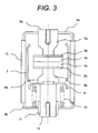
- FIG. 3 shows the structure of a vacuum interrupter manufactured in a third embodiment of the present invention.
- the fixed electrode 6a in FIG. 3 comprises a fixed electrical contact 1a, a reinforcing plate 3a, and fixed electrode rod 4a.
- the movable electrode 6b comprises a movable electrical contact 1b, a reinforcing plate 3b, and movable electrode rod 4b.
- the movable electrode 6b is brazed to a movable holder 12 through a movable-side shield 8 for preventing metal vapor and the like from spattering during interruption.
- These members are hermetically sealed in a high vacuum by a fixed-side end plate 9a, a movable-side end plate 9b, and an insulating cylinder 13, the fixed electrode 6a being brazed to the fixed-side end plate 9a, the movable holder 12 being brazed to the movable-side end plate 9b.
- the fixed electrode 6a and movable holder 12 are connected to external conductors through their threads.
- a shield 7 for preventing metal vapor and the like from spattering during interruption is provided on the internal surface of the insulating cylinder 13.
- a guide 11 for supporting a sliding part is provided between the movable-side end plate 9b and movable holder 12.
- a bellows 10 is provided between the movable-side shield 8 and movable-side end plate 9b so that the movable holder 12 is moved upward and downward with the inside of the vacuum chamber kept in a vacuum to open and close the fixed electrode 6a and movable electrode 6b.
- electrical contacts manufactured in the first embodiment were used as the electrical contacts 1a and 1b shown in FIG. 3 to manufacture a vacuum interrupter.
- a vacuum circuit breaker in which the vacuum interrupter manufactured in the third embodiment was mounted was manufactured.
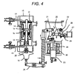
- FIG. 4 shows the structure of a vacuum circuit breaker in a fourth embodiment of the present invention.
- the vacuum circuit breaker is structured so that an operation mechanism is provided on the front and three epoxy cylinders 15, which support the vacuum interrupter 14 and integrally form three phases, are provided on the back.
- the vacuum interrupter 14 is opened and closed by the operation mechanism through an isolated operation rod 16.
- a trip coil 27 is energized and a trip lever 28 disengages the prop 22.
- the main lever 26 then turns, opening the electrodes.
- the reference numeral 31 indicates an exhaust cylinder.
Landscapes
- Contacts (AREA)
- High-Tension Arc-Extinguishing Switches Without Spraying Means (AREA)
- Powder Metallurgy (AREA)
- Manufacture Of Switches (AREA)
Abstract
The powder of one of a refractory metal C, Mo, or W and the powder of a highly conductive metal Cu are mixed together, the resulting mixture is pressurized to form a complex pressed body with a relative density of 65% or higher, and the complex pressed body is heated to a temperature not higher than the melting point of Cu to sinter the complex pressed body. The content V (percent by volume) of the refractory metal is within the range obtained from equations (1) and (2) shown below, in which M represents the atomic weight of the refractory metal; a boundary between the refractory metal and highly conductive metal on an arbitrary cross section is physically separated over at least 70% of the length of the boundary. 

Accordingly, the present invention can provide an electrical contact that achieves both low strength, which results in a reduction in force with which a contact bridge formed by melting is broken, and high density for ensuring current-carrying and interruption performance, and thereby enables the electrical current switch and other elements to be substantially compact.
Description
- The present invention relates to electrical contacts for flowing and interrupting a current in a vacuum or in the air.
- Circuit breakers and electrical current switches, which are protective units in electric power reception and distribution systems, are required to be compact and inexpensive and to offer high performance, making it necessary to simplify these units. Accordingly, when the electrical contacts for flowing and interrupting a current are melted due to joule heat, they are preferably separated with a small force; the small force enables an operating mechanism for opening and closing the electrical contacts to be compact. It is also preferable that the electrical contacts can flow and interrupt a current correctly not only in a vacuum but also in a gas atmosphere, for example, in the air. Then, a vacuum chamber and the like become unnecessary. The structure can be simplified and deterioration in functionality due to atmospheric abnormalities and other problems can be avoided.
- Electrical contacts need to have superior current-carrying performance. Accordingly, conventional electrical contacts made of metal materials have been densified by using a melting process so that the contacts can be separated with a force reduced by, for example, dispersing fine particles of a metal with a high melting point.
- Conventional electrical contacts employed in switchgears for electric power have been using Cr-Cu as the main component, which is obtained by combining Cr, which is an arc resistant component, with Cu, which is a superior conductor. The dominant method of manufacturing the electrical contacts has been the melted-infiltration process, in which high densification can be easily carried out, as disclosed in Japanese Patent Laid-open No.
Hei 10(1998)-241512 2000-173415 - When closed, electrical contacts of this type have large contact resistance due to their density and high strength. If the contacts are melted due to joule heat, a large force is needed to separate them, making the operating mechanism large. To reduce the force with which the contacts are separated, the electrical contacts have been improved by, for example, dispersing fine particles of a hard metal with a high melting point. However, reduction in current-carrying performance, an accompanying increase in joule heat, and other problems have been caused, so such an improvement has not been a basic countermeasure.
- An object of the present invention is to provide an electrical contact that can achieve both low strength, which results in a reduction in force with which a contact bridge formed by melting is broken, and high density for ensuring current-carrying and interruption performance by using a refractory metal appropriate as the arc resistant component, and thereby enables the electrical current switch and other elements to be compact.
- In one aspect of the electrical contact according to the present invention, the electrical contact comprises a refractory metal, a highly conductive metal, and an inevitable impurity; the content V (percent by volume) of the refractory metal is within the range obtained from equations (1) and (2) shown below, in which M represents the atomic weight of the refractory metal; a boundary between the refractory metal and highly conductive metal has a cross sectional texture that is physically separated over at least 70% of the length of the boundary.


- In another aspect of the electrical contact according to the present invention, the refractory metal of the electrical contact is made of one of C, Mo, or W, the highly conductive metal is Cu, and the diameters of particles of the refractory metal are within the range of 10 µm to 104 µm.
- In still another aspect of the electrical contact according to the present invention, a boundary between the refractory metal and highly conductive metal has a cross sectional texture that is physically separated over at least 70% of the length of the boundary, and the electrical contacts has porosity within the range of 0.2 to 5 percent by volume.
- In one aspect of the electrical contact manufacturing method according to the present invention, refractory metal powder and highly conductive metal powder are mixed together, the resulting mixture is pressurized to form a complex pressed body with a relative density of 65% or higher, and the complex pressed body is heated to a temperature not higher than the melting point of the highly conductive metal to sinter the complex pressed body.
- A preferred embodiment of the present invention can provide an electrical contact that can achieve both low strength, which results in a reduction in force with which a contact bridge formed by melting is broken, and high density for ensuring current-carrying and interruption performance by using a refractory metal appropriate as the arc resistant component, and thereby enables the electrical current switch and other elements to be compact.
- Other objects and features of the present invention will be clarified in embodiments described below.
-
-
FIG. 1 is an electric microscopic image showing an example of the texture of an electrical contact material in a first embodiment of the present invention. -
FIG. 2 is a cross sectional view showing the structure of an electrode manufactured in a second embodiment of the present invention. -
FIG. 3 shows the structure of a vacuum interrupter manufactured in a third embodiment of the present invention. -
FIG. 4 shows the structure of a vacuum circuit breaker manufactured in a fourth embodiment of the present invention. - The inventors considered that causing physical separation on a boundary between a refractory metal particle and a Cu matrix is an effective way to have an electrical contact material achieve both high density and low strength, and found refractory materials having textures that cause physical separation of this type as well as the content of the refractory metal. In general, refractory metal components used in electrical contacts have a melting point higher than about 1800°C.
- On the basis of this finding, an electrical contact was manufactured, which comprised a refractory metal, a highly conductive metal, and an inevitable impurity, and the content V (percent by volume) of the refractory metal was set within the range obtained from equations (1) and (2) shown below, in which M represents the atomic weight of the refractory metal. When the refractory metal was included within this range, both superior current-carrying and interruption performance and superior resistance to adhesion due to melting can be achieved. When the content of the refractory metal was smaller than this range, a reduction in strength due to physical separation between the refractory metal particles and highly conductive metal matrix was insufficient. When the content of the refractory metal exceeded the range, the resistance to adhesion due to melting and the current-carrying performance were lowered due to an insufficient density, an increase in electric resistance, and other factors.


- When the refractory metal used in the electrical contact that embodies the present invention is one of C, Mo, or W and the highly conductive metal is Cu, the effect described above can be adequately obtained. This is because, out of the refractory metals, C, Mo, and W are particularly superior in that they cause neither reactions with Cu nor solid solution and cause boundary separation with relative ease. The diameters of particles in the refractory metal used are preferably within the range of 10 µm to 104 µm. Residual stress was caused on a boundary between the refractory metal and highly conductive metal matrix due to a difference in thermal expansion between them. When the particle diameter of the refractory metal was smaller than this range, the residual stress was small and separation between the refractory metal and highly conductive metal matrix was insufficient. When the particle diameter exceeded this range, dispersion of the refractory metal became uneven, making the electrical performance of the contact unstable.
- With the cross sectional texture of the electrical contact that embodies the present invention, a boundary between the refractory metal and highly conductive metal on an arbitrary cross section is physically separated over at least 70% of the length of the boundary. Accordingly, the porosity of the electrical contact material falls within the range of 0.2 to 5 percent by volume. When the electrical contact has textures of this type, it can achieve both the high density and low strength described above.
- In a preferable method of manufacturing the novel electrical contact, refractory metal powder and highly conductive metal powder are mixed together, the resulting mixture is pressurized to form a complex pressed body with a relative density of 65% or higher, and the complex pressed body is heated to a temperature not higher than the melting point of the highly conductive metal to sinter the complex pressed body. By this method, textures in which the refractory metal and highly conductive metal are evenly mixed together are obtained and a separation state in which voids are formed on a boundary between the refractory metal and highly conductive metal can also be obtained, enabling a greatly reduced force to be sufficient for separation after melting. The voids can be thought to have been formed in the boundary due to a difference in contraction between the refractory metal and highly conductive metal during cooling in the sintering process, the difference in contraction being caused by a difference in the coefficient of thermal expansion therebetween. That is, since the highly conductive metal has a larger coefficient of thermal expansion than the refractory metal, the highly conductive metal largely contracts during the cooling, causing tensile stress in the highly conductive metal matrix near the boundary. When the sintered complex pressed body is cut in this state to observe its cross section, the stress is relieved and separation occurs on the boundary, forming voids. When tensile strength is applied, stress is also relieved from the highly conductive metal due to cutting in the same way. Cracks then proceed along the separated boundary, forming voids. It is effective to cause residual tensile stress in the highly conductive metal matrix near the boundary in the sintering process as described above. To cause residual tensile stress, the cooling rate in the sintering process is preferably 6°C/min to 35°C/min. In this method, a metal mold having a final shape of the electrical contact can be used to obtain a complex pressed body by near net shape forming. Accordingly, machining after the sintering process can be eliminated and thereby the electrical contact can be manufactured at a low cost.
- In the switchgear for electric power that embodies the present invention, a pair of electrical contacts of the type described above are oppositely disposed to have a function for flowing and interrupting a current. Therefore, a compact, inexpensive switchgear for electric power can be provided, which is superior in interruption performance and current-carrying performance, needs only a small force for separating the melted electrical contacts, and has a compact operating mechanism.
- Electrical contact materials having compositions shown in Table 1 were manufactured and their performance was evaluated in simple tests. Each electrical contact material was manufactured as described below. First, C powder, Mo powder, or W powder with particle diameters shown in Table 1 and Cu powder with particle diameters of 60 µm or less was mixed together with a V-type mixer at a compounding ratio at which a composition shown in Table 1 was obtained. The mixed powder was then loaded in a disk-shaped metal mold, and molded by a hydraulic press under a pressure of 294 MPa. The density of the resulting complex pressed body was about 72%. The complex pressed body material was heated in a vacuum at about 10-2 Pa for two hours at 1060°C, after which the complex pressed body was cooled at a rate of about 13°C per minute to form an electrical contact material. A contact material made of only Cu powder was also manufactured in the same way for use as a criterion. The porosity of the obtained contact material was measured by the in-water Archimedes method.
- Electrical contacts with a diameter of 20 mm and a thickness of 20 mm were obtained from the obtained contact material by machining. The electrical contacts then underwent a performance evaluation test in the air (atmosphere). In the test, a simplified apparatus having a pair of oppositely disposed current-carrying rods, which can be brought into contact and separated, was used. The obtained electrical contacts were brazed to the ends of the current-carrying rods. After an electric power of 50 kV·kA (voltage × current) was applied, the force needed to separate the contacts (separation force) was measured. It was also verified whether a current of 1250A could be interrupted. Electrical conductivity (current-carrying ease) was measured by using an electrical conductivity measuring instrument based on the eddy current method. Table 1 also shows the evaluation results.
[Table 1] Class No. Composition (percent by volume) Particle diameter of refractory metal (µm) Porosity (percent by volume) Performance test results Remarks Cu Refractory metal Electrical conductivity (relative value) Separation force * (relative value) Interruption of 1250A (○: possible, ×; Not possible) C Mo w Present invention 1 Rest 1 - - 10-22 0.2 1.0 0.75 ○ 2 2.5 - - 2.6 0.95 0.6 ○ 3 4 - - 4.1 0.9 0.55 ○ 4 - 8 - 45-75 1.3 0.9 0.7 ○ 5 - 20 - 2.3 0.75 0.35 ○ 6 - 32 - 2.9 0.65 0.5 ○ 7 - - 15.5 45-104 2.4 0.85 0.5 ○ 8 - - 38 3.9 0.7 0.55 ○ 9 - - 61 5.0 0.65 0.4 ○ Comparative examples 10 - - - - 0.1 1.0 1.0 ○ Values on which relative values are based 11 0.5 - - 10-22 0.1 1.0 0.9 ○ The content of the refractory metal was out range. 12 4.5 - - 4.4 0.9 0.5 × 13 - 7 - 45-75 1.1 0.95 0.8 ○ 14 - 33.5 - 3.3 0.55 0.4 ○ 15 - - 14.5 45-104 2.1 0.9 0.8 ○ 16 - - 62.5 5.6 0.5 0.35 × 17 - 20 - <5 3.6 0.55 0.7 ○ The particle diameter of the refractory metal was out of range. 18 - 20 - >147 1.2 0.85 0.8 ○ * Separation force after an electric power of 50 kV·kA (voltage × current) was applied - The electrical conductivity and separation force in Table 1 are indicated by values relative to measurements of the electrical contact No. 10 made only of Cu.
- The electric conductivities of the electrical contacts Nos. 1 to 9 in the experimental examples in the present invention were 0.65 or higher, indicating superior current-carrying performance. Their separation forces were 0.75 or less, indicating that they were adequately reduced. All these electrical contacts could interrupt a current of 1250A. The porosity fell within the range of 0.2 to 5.0 percent by volume.
- Now the comparative materials will be considered for comparison. The separation force of electrical contact No. 11, with a C content lower than the range in the present invention, was not adequately reduced. The current interruption performance of electrical contact No. 12, with a C content higher than the range in the present invention, was low. The separation force of electrical contact No. 13, with an Mo content lower than the range in the present invention, was not adequately reduced. The electrical conductivity (current-carrying performance) of electrical contact No. 14, with an Mo content higher than the range in the present invention, was low. The separation force of electrical contact No. 15, with a W content lower than the range in the present invention, was not adequately reduced. The electrical conductivity of electrical contact No. 16, with a W content higher than the range in the present invention, was significantly reduced, and its interruption performance was also low. The electrical conductivity of electrical contact No. 17, with Mo particle diameters smaller than the range in the present invention, was inadequate. The separation force of electrical contact No. 18, with Mo particle diameters larger than the range in the present invention, was not adequately reduced. A possible reason why electrical contact No. 11 had a large separation force is that separation between C and Cu was inadequate due to a porosity smaller than the range of the present invention. For electrical contact No. 16, since the porosity was larger than the range of the present invention and thereby the electrical conductivity was substantially reduced, the interruption performance can be considered to become inadequate.
- The textures in the cross sections of the electrical contacts Nos. 1 to 9 in the experimental examples in the present invention were observed with a scanning electron microscope.
-
FIG. 1 is a photo of the cross section of electrical contact No. 5 in Table 1, which was taken with the scanning electron microscope as an example of an electrical contact that embodies the present invention. As the photo shows, there are voids with a width of less than 1 µm in a boundary between a refractory metal particle and a Cu matrix, physically separating them. In measurements obtained from electron microscopic images, the ratio of the voids to the boundary was in the range of 70% to 90% for all electrical contacts. As for the electrical contacts in this embodiment, the force with which contacts were separated was reduced due to these voids. - It was confirmed that the electrical contacts in this embodiment have superior performance as contacts used in the air. In an evaluation test in a vacuum chamber at about 10-1 Pa, a similar tendency was obtained.
- Electrodes used in a switchgear for electric power was manufactured by using an electrical contact material obtained in the first embodiment.
-
FIG. 2 is a cross sectional view showing the structure of an electrode manufactured in a second embodiment of the present invention. As shown inFIG. 2 , the electrode comprises anelectrical contact 1 withslits 2 for giving a driving force to an arc, a reinforcingplate 3 made of stainless steel, anelectrode rod 4, and abrazing material 5. The electrode was manufactured as described below. Theelectrode rod 4 and reinforcingplate 3 were prepared in advance from oxygen-free copper and SUS304, respectively, by machining. Abrazing material 5 was placed between theelectrical contact 1 and reinforcingplate 3 and between the reinforcingplate 3 andelectrode rod 4. The resulting assembly was heated for 10 minutes at 970°C in a vacuum at 8.2 × 10⁻⁴ Pa or lower to obtain the electrode shown inFIG. 2 . If the strength of theelectrical contact 1 is adequate, the reinforcingplate 3 may be omitted. When this electrode is integrally joined to an air circuit breaker in an electrical current switch by a metallurgical method, the electrode can be used as an air contact. Thereference numeral 44 indicates a central hole. - The
electrical contact 1 having a complex shape as described above can also be manufactured by loading mixed powder into a metal mold that can form a final shape and then performing sintering. In this method, post-processing such as machining is not necessary, so theelectrical contact 1 can be easily manufactured. - A pair of electrodes manufactured in the second embodiment were oppositely disposed in a vacuum chamber to manufacture a vacuum interrupter.
-
FIG. 3 shows the structure of a vacuum interrupter manufactured in a third embodiment of the present invention. The fixedelectrode 6a inFIG. 3 comprises a fixedelectrical contact 1a, a reinforcingplate 3a, and fixedelectrode rod 4a. Similarly, themovable electrode 6b comprises a movableelectrical contact 1b, a reinforcingplate 3b, andmovable electrode rod 4b. Themovable electrode 6b is brazed to amovable holder 12 through a movable-side shield 8 for preventing metal vapor and the like from spattering during interruption. These members are hermetically sealed in a high vacuum by a fixed-side end plate 9a, a movable-side end plate 9b, and an insulatingcylinder 13, the fixedelectrode 6a being brazed to the fixed-side end plate 9a, themovable holder 12 being brazed to the movable-side end plate 9b. The fixedelectrode 6a andmovable holder 12 are connected to external conductors through their threads. Ashield 7 for preventing metal vapor and the like from spattering during interruption is provided on the internal surface of the insulatingcylinder 13. Aguide 11 for supporting a sliding part is provided between the movable-side end plate 9b andmovable holder 12. A bellows 10 is provided between the movable-side shield 8 and movable-side end plate 9b so that themovable holder 12 is moved upward and downward with the inside of the vacuum chamber kept in a vacuum to open and close the fixedelectrode 6a andmovable electrode 6b. - As described above, electrical contacts manufactured in the first embodiment were used as the
electrical contacts FIG. 3 to manufacture a vacuum interrupter. - A vacuum circuit breaker in which the vacuum interrupter manufactured in the third embodiment was mounted was manufactured.
-
FIG. 4 shows the structure of a vacuum circuit breaker in a fourth embodiment of the present invention. - The vacuum circuit breaker is structured so that an operation mechanism is provided on the front and three
epoxy cylinders 15, which support thevacuum interrupter 14 and integrally form three phases, are provided on the back. Thevacuum interrupter 14 is opened and closed by the operation mechanism through anisolated operation rod 16. - When the vacuum circuit breaker is closed, a current flows through an
upper terminal 17, theelectrical contact 1, acurrent corrector 18, and alower terminal 19. The contact force between the electrodes is maintained by acontact spring 20 loaded in theisolated operation rod 16. The contact force between the electrodes and a magnetic force generated by a short-circuit current are maintained by asupport lever 21 and aprop 22. When acoil 30 is energized in an open circuit state, aplunger 23 raises aroller 25 through a knockingrod 24 and thereby amain lever 26 is turned, closing the electrodes. The closed circuit is maintained by thesupport lever 21. - When the vacuum circuit breaker is in a trip-free state, a
trip coil 27 is energized and atrip lever 28 disengages theprop 22. Themain lever 26 then turns, opening the electrodes. - When the vacuum circuit breaker is in an open circuit state, the link is restored by a
reset spring 29 after the electrodes open, and theprop 22 engages. When acoil 30 is energized in this state, the circuit is closed. Thereference numeral 31 indicates an exhaust cylinder.
Claims (7)
- An electrical contact, comprising:a refractory metal;a highly conductive metal; andan inevitable impurity; whereinthe content V (percent by volume) of the refractory metal is within a range obtained from equations (1) and (2) shown below, in which M represents the atomic weight of the refractory metal; anda boundary between the refractory metal and the highly conductive metal on an arbitrary cross section is physically separated over at least 70% of the length of the boundary.


- The electrical contact according to claim 1, wherein:the refractory metal is any one of C, Mo, or W; andthe highly conductive metal is Cu.
- The electrical contact according to claim 1, wherein the diameter of a particle of the refractory metal is within a range of 10 µm to 104 µm.
- The electrical contact according to claim 1, wherein the electrical contact has a porosity of 0.2 to 5 percent by volume.
- A switchgear for electric power, comprising:a pair of electrical contacts described in claim 1; anda mechanism for closing and opening the pair of electrical contacts.
- A method of manufacturing an electrical contact, comprising the steps of:mixing refractory metal powder and highly conductive metal powder together;pressurizing the resulting mixture to form a complex pressed body with a relative density of 65% or higher; andheating the complex pressed body to a temperature not higher than the melting point of the highly conductive metal to sinter the complex pressed body.
- The method according to claim 6, wherein the refractory metal powder is any one of a powder of C including particles with a diameter of 10 µm to 22 µm, Mo including particles with a diameter of 45 µm to 75 µm, or W including particles with a diameter of 45 µm to 104 µm.
Applications Claiming Priority (1)
| Application Number | Priority Date | Filing Date | Title |
|---|---|---|---|
| JP2008225411A JP2010061935A (en) | 2008-09-03 | 2008-09-03 | Electrical contacts, methods of manufacturing the same, and switchgear for electric power |
Publications (1)
| Publication Number | Publication Date |
|---|---|
| EP2161728A2 true EP2161728A2 (en) | 2010-03-10 |
Family
ID=41258742
Family Applications (1)
| Application Number | Title | Priority Date | Filing Date |
|---|---|---|---|
| EP09008630A Withdrawn EP2161728A2 (en) | 2008-09-03 | 2009-07-01 | Electrical contacts and methods of manufacturing the same, and switchgear for electric power |
Country Status (3)
| Country | Link |
|---|---|
| EP (1) | EP2161728A2 (en) |
| JP (1) | JP2010061935A (en) |
| CN (1) | CN101667496A (en) |
Cited By (1)
| Publication number | Priority date | Publication date | Assignee | Title |
|---|---|---|---|---|
| CN102259188A (en) * | 2011-07-20 | 2011-11-30 | 温州银泰合金材料有限公司 | Method for producing high-energy rare earth powder alloy electrical contact material |
Families Citing this family (3)
| Publication number | Priority date | Publication date | Assignee | Title |
|---|---|---|---|---|
| KR101115639B1 (en) | 2010-10-18 | 2012-02-15 | 엘에스산전 주식회사 | Contact assembly of the vacuum interrupter |
| JP6273869B2 (en) * | 2014-01-31 | 2018-02-07 | セイコーエプソン株式会社 | Method for manufacturing molded body and method for manufacturing structure |
| CN109355541B (en) * | 2018-12-17 | 2020-01-17 | 东北大学 | A kind of method for preparing high density tungsten copper alloy |
Citations (1)
| Publication number | Priority date | Publication date | Assignee | Title |
|---|---|---|---|---|
| JP2000173415A (en) | 1998-12-01 | 2000-06-23 | Hitachi Ltd | Electrical contact and method of manufacturing the same |
Family Cites Families (3)
| Publication number | Priority date | Publication date | Assignee | Title |
|---|---|---|---|---|
| JPS61227330A (en) * | 1985-03-30 | 1986-10-09 | 株式会社東芝 | Manufacture of contact material for vacuum valve |
| JPH05242773A (en) * | 1992-02-26 | 1993-09-21 | Meidensha Corp | Vacuum interrupter electrode material |
| JP2003223834A (en) * | 2002-01-31 | 2003-08-08 | Hitachi Ltd | Electrical contact members and their manufacturing method |
-
2008
- 2008-09-03 JP JP2008225411A patent/JP2010061935A/en active Pending
-
2009
- 2009-07-01 EP EP09008630A patent/EP2161728A2/en not_active Withdrawn
- 2009-08-20 CN CN200910166606A patent/CN101667496A/en active Pending
Patent Citations (1)
| Publication number | Priority date | Publication date | Assignee | Title |
|---|---|---|---|---|
| JP2000173415A (en) | 1998-12-01 | 2000-06-23 | Hitachi Ltd | Electrical contact and method of manufacturing the same |
Non-Patent Citations (2)
| Title |
|---|
| F.S.JAYARAMAN ET AL., INTERNATIONAL JOURNAL OF FOOD SCIENCE AND TECHNOLOGY, vol. 25, 1990, pages 47 - 60 |
| K.S.JAYARAMAN ET AL., INTERNATIONAL JOURNAL OF FOOD SCIENCE AND TECHNOLOGY, vol. 25, 1990, pages 47 - 60 |
Cited By (2)
| Publication number | Priority date | Publication date | Assignee | Title |
|---|---|---|---|---|
| CN102259188A (en) * | 2011-07-20 | 2011-11-30 | 温州银泰合金材料有限公司 | Method for producing high-energy rare earth powder alloy electrical contact material |
| CN102259188B (en) * | 2011-07-20 | 2013-06-12 | 温州银泰合金材料有限公司 | Method for producing high-energy rare earth powder alloy electrical contact material |
Also Published As
| Publication number | Publication date |
|---|---|
| JP2010061935A (en) | 2010-03-18 |
| CN101667496A (en) | 2010-03-10 |
Similar Documents
| Publication | Publication Date | Title |
|---|---|---|
| EP2081200B1 (en) | Electrical contact for vacuum interrupter | |
| EP0634766B1 (en) | Vacuum circuit breaker and electric contact used in same | |
| CN1776855B (en) | Electrode, electrical contact and method of manufacturing the same | |
| EP1528581B1 (en) | Electrical contact, method of manufacturing the same, electrode for vacuum interrupter, and vacuum circuit breaker | |
| EP3098829B1 (en) | Method for producing electrode material | |
| CN110036454B (en) | Improved electrical contact alloy for vacuum contactor | |
| EP3062327A1 (en) | Electrical contact for vacuum valve and process for producing same | |
| EP2161728A2 (en) | Electrical contacts and methods of manufacturing the same, and switchgear for electric power | |
| EP2323148A1 (en) | Electric contact and vacuum interrupter using the same | |
| EP2709132A2 (en) | Electrical contacts, manufacturing method thereof, electrode, vacuum interrupter, and electric power switches | |
| JP3428416B2 (en) | Vacuum circuit breaker, vacuum valve and electric contact used therefor, and manufacturing method | |
| EP1742238B1 (en) | Electrical contacts for vacuum circuit breakers and methods of manufacturing the same | |
| US20060081560A1 (en) | Vacuum circuit breaker, vacuum interrupter, electric contact and method of manufacturing the same | |
| JP2006147263A (en) | Vacuum circuit breaker electrode, vacuum valve and manufacturing method thereof | |
| JP4988489B2 (en) | Electrical contact | |
| JP5159947B2 (en) | Electrical contact for vacuum valve and vacuum circuit breaker using the same | |
| JPH1150177A (en) | Contact material for vacuum circuit breaker, manufacturing method thereof and vacuum circuit breaker | |
| CN114270460A (en) | Electric contact, vacuum valve with electric contact, and method for manufacturing electric contact | |
| EP2362400A2 (en) | Electrical contact and switch device using same | |
| JP3443516B2 (en) | Manufacturing method of contact material for vacuum valve | |
| JPH04206411A (en) | Electrode materials for vacuum circuit breakers and vacuum circuit breakers |
Legal Events
| Date | Code | Title | Description |
|---|---|---|---|
| PUAI | Public reference made under article 153(3) epc to a published international application that has entered the european phase |
Free format text: ORIGINAL CODE: 0009012 |
|
| AK | Designated contracting states |
Kind code of ref document: A2 Designated state(s): AT BE BG CH CY CZ DE DK EE ES FI FR GB GR HR HU IE IS IT LI LT LU LV MC MK MT NL NO PL PT RO SE SI SK SM TR |
|
| AX | Request for extension of the european patent |
Extension state: AL BA RS |
|
| 17P | Request for examination filed |
Effective date: 20100211 |
|
| STAA | Information on the status of an ep patent application or granted ep patent |
Free format text: STATUS: THE APPLICATION HAS BEEN WITHDRAWN |
|
| 18W | Application withdrawn |
Effective date: 20100902 |