EP2161358A1 - Weft-insertion-condition display method for loom - Google Patents
Weft-insertion-condition display method for loom Download PDFInfo
- Publication number
- EP2161358A1 EP2161358A1 EP09010885A EP09010885A EP2161358A1 EP 2161358 A1 EP2161358 A1 EP 2161358A1 EP 09010885 A EP09010885 A EP 09010885A EP 09010885 A EP09010885 A EP 09010885A EP 2161358 A1 EP2161358 A1 EP 2161358A1
- Authority
- EP
- European Patent Office
- Prior art keywords
- weft
- display
- statistics
- displayed
- loom
- Prior art date
- Legal status (The legal status is an assumption and is not a legal conclusion. Google has not performed a legal analysis and makes no representation as to the accuracy of the status listed.)
- Granted
Links
- 238000000034 method Methods 0.000 title claims description 16
- 238000003780 insertion Methods 0.000 claims abstract description 123
- 230000037431 insertion Effects 0.000 claims abstract description 98
- 238000009941 weaving Methods 0.000 claims abstract description 78
- 238000005070 sampling Methods 0.000 claims abstract description 64
- 230000008859 change Effects 0.000 claims abstract description 33
- 230000005856 abnormality Effects 0.000 description 64
- 238000001514 detection method Methods 0.000 description 23
- 239000004744 fabric Substances 0.000 description 10
- 238000010586 diagram Methods 0.000 description 8
- 230000004044 response Effects 0.000 description 8
- 239000003086 colorant Substances 0.000 description 7
- 239000006185 dispersion Substances 0.000 description 6
- 230000008569 process Effects 0.000 description 6
- 230000001276 controlling effect Effects 0.000 description 4
- 230000002093 peripheral effect Effects 0.000 description 4
- 230000001105 regulatory effect Effects 0.000 description 4
- 230000002159 abnormal effect Effects 0.000 description 2
- 238000004891 communication Methods 0.000 description 2
- 239000012530 fluid Substances 0.000 description 2
- 238000004804 winding Methods 0.000 description 2
- 235000014676 Phragmites communis Nutrition 0.000 description 1
- 238000009825 accumulation Methods 0.000 description 1
- 230000003213 activating effect Effects 0.000 description 1
- 238000010009 beating Methods 0.000 description 1
- 230000007423 decrease Effects 0.000 description 1
- 238000012986 modification Methods 0.000 description 1
- 230000004048 modification Effects 0.000 description 1
- 238000012545 processing Methods 0.000 description 1
- 230000009467 reduction Effects 0.000 description 1
- 230000000452 restraining effect Effects 0.000 description 1
- 230000000717 retained effect Effects 0.000 description 1
- XLYOFNOQVPJJNP-UHFFFAOYSA-N water Substances O XLYOFNOQVPJJNP-UHFFFAOYSA-N 0.000 description 1
Images



Classifications
-
- D—TEXTILES; PAPER
- D03—WEAVING
- D03J—AUXILIARY WEAVING APPARATUS; WEAVERS' TOOLS; SHUTTLES
- D03J1/00—Auxiliary apparatus combined with or associated with looms
- D03J1/005—Displays or displaying data
-
- D—TEXTILES; PAPER
- D03—WEAVING
- D03D—WOVEN FABRICS; METHODS OF WEAVING; LOOMS
- D03D47/00—Looms in which bulk supply of weft does not pass through shed, e.g. shuttleless looms, gripper shuttle looms, dummy shuttle looms
- D03D47/28—Looms in which bulk supply of weft does not pass through shed, e.g. shuttleless looms, gripper shuttle looms, dummy shuttle looms wherein the weft itself is projected into the shed
- D03D47/30—Looms in which bulk supply of weft does not pass through shed, e.g. shuttleless looms, gripper shuttle looms, dummy shuttle looms wherein the weft itself is projected into the shed by gas jet
- D03D47/3026—Air supply systems
- D03D47/3053—Arrangements or lay out of air supply systems
-
- D—TEXTILES; PAPER
- D03—WEAVING
- D03D—WOVEN FABRICS; METHODS OF WEAVING; LOOMS
- D03D47/00—Looms in which bulk supply of weft does not pass through shed, e.g. shuttleless looms, gripper shuttle looms, dummy shuttle looms
- D03D47/28—Looms in which bulk supply of weft does not pass through shed, e.g. shuttleless looms, gripper shuttle looms, dummy shuttle looms wherein the weft itself is projected into the shed
- D03D47/30—Looms in which bulk supply of weft does not pass through shed, e.g. shuttleless looms, gripper shuttle looms, dummy shuttle looms wherein the weft itself is projected into the shed by gas jet
- D03D47/3066—Control or handling of the weft at or after arrival
- D03D47/3073—Detection means therefor
-
- D—TEXTILES; PAPER
- D03—WEAVING
- D03D—WOVEN FABRICS; METHODS OF WEAVING; LOOMS
- D03D47/00—Looms in which bulk supply of weft does not pass through shed, e.g. shuttleless looms, gripper shuttle looms, dummy shuttle looms
- D03D47/28—Looms in which bulk supply of weft does not pass through shed, e.g. shuttleless looms, gripper shuttle looms, dummy shuttle looms wherein the weft itself is projected into the shed
- D03D47/30—Looms in which bulk supply of weft does not pass through shed, e.g. shuttleless looms, gripper shuttle looms, dummy shuttle looms wherein the weft itself is projected into the shed by gas jet
- D03D47/3093—Displaying data
Definitions
- the present invention relates to a display method which is used in a display device provided in a loom to graphically display statistics regarding a weft insertion condition along a time axis and which facilitates a determination of the cause of an abnormality when the abnormality occurs in the statistics.
- Patent Document 1 Japanese Unexamined Patent Application Publication No. 2006-9233 discloses an invention titled "WEFT-INSERTION-CONDITION DISPLAY UNIT FOR LOOM". According to this invention, statistics regarding a weft insertion condition are graphically displayed along the time axis in time series. According to the technique described in Patent Document 1, a graphical display is shown such that time-series variation in the statistics of weft arrival angles during weft insertion in each predetermined sampling period can be visually recognized. Therefore, it can be determined whether or not an abnormality, such as dispersion, has occurred in the weft arrival angles in each sampling period on the basis of the variation in the statistics.
- an abnormality such as dispersion
- occurrence status of weft insertion failures may also be displayed along the same time axis as the time axis along which the statistics are displayed, so that causes of an abnormality in the weft insertion operation can be determined.
- whether or not a weft insertion failure has occurred and the type of the weft insertion failure can be determined for each sampling period.
- the cause of the abnormality is preferably determined as soon as possible. If, for example, the cause of the abnormality is a root cause, such as an abnormality in a weft yarn or a yarn supplier being used or an abnormality in a weft insertion device, the cause must be eliminated soon since the situation will continue unless the cause is eliminated. Therefore, if there is an abnormality in the statistics as described above, it is preferable that the cause of the abnormality can be easily determined.
- the occurrence status of weft insertion failures is displayed along the same time axis as the time axis along which the statistics are displayed. Therefore, the relationship between the statistics regarding weft arrival times and the occurrence status of weft insertion failures can be recognized.
- other kinds of information cannot be obtained. Therefore, the cause of the abnormality in the statistics cannot be easily determined and it takes a long time to determine the cause.
- an object of the present invention is to provide a display method which is used in a display device of a loom having a display function of graphically displaying statistics regarding a weft insertion condition in the loom along a time axis and which facilitates a determination of the cause of an abnormality when the abnormality occurs in the statistics.
- information regarding a change in a weaving condition is displayed on the same screen as a display screen on which the statistics regarding weft arrival times are displayed.
- a weft-insertion-condition display method is used in a loom which includes a display device and in which a weft arrival time is detected each time a weft insertion operation is performed.
- the display device calculates statistics regarding the weft arrival times for each of predetermined sampling periods on the basis of the detected weft arrival times, stores the statistics that are sequentially calculated during a weaving operation in time series, and graphically displays the stored statistics in time series along a time axis.
- the weft-insertion-condition display method includes the step of displaying information regarding a change in a weaving condition on the same screen as a display screen on which the statistics are displayed.
- the above-mentioned "weaving condition” includes conditions regarding the weft insertion operation and conditions regarding warp yarns and woven cloth.
- the "weaving condition” regarding the weft insertion operation includes, for example, a weft insertion start time and/or a stopper-pin retracting time at which the stopper pin is retracted in a measuring-and-storing device.
- the weft insertion start time includes an ejection start time of a main nozzle used in the weft insertion operation, and also includes an ejection start time of an auxiliary main nozzle in the case where the loom includes the auxiliary main nozzle.
- the "weaving condition" regarding the weft insertion operation also includes an ejection pressure and an ejection stop time of the main nozzle (and those of the auxiliary main nozzle) and an ejection pressure, an ejection start time, and an ejection stop time of sub-nozzles (each group of sub-nozzles) used in the weft insertion operation.
- an activating time of the weft yarn brake is also included in the conditions regarding the weft insertion operation.
- the "weaving condition" regarding the warp yarns and the woven cloth includes, for example, a set tension of the warp yarns, a set weaving density of the woven cloth, a shedding pattern, and a rotational speed of the main shaft of the loom.
- the above-described state in which the information regarding the change in the weaving condition and the statistics are "displayed on the same screen” includes the state in which a display screen of the information regarding the change in the weaving condition (hereinafter also referred to as “weaving-condition change information”) is shown in an additional window and is placed on the graphical display which shows the statistics regarding the weft arrival angles (hereinafter also referred to as “statistics display”).
- the above-mentioned state also includes the state in which the display screen for the statistics display and the display screen for the weaving-condition change information are shown next to each other on a screen of the display device instead of being superimposed on each other.
- the above-described state also includes a display mode in which the statistics display and the weaving-condition change information are displayed together on a single display screen.
- the information regarding the change in the weaving condition includes an input history regarding a change in a setting of the weaving condition.
- the "input history" may be a list of information regarding changes in set values of weaving conditions made by the operator in a certain time period on the time axis, the information being arranged in order of time on the time axis.
- the information regarding the changes in the set values include, for example, a change in the set value for the ejection stop time of the main nozzle from 170° to 180°.
- the information regarding the change in the weaving condition is displayed on the same screen as a screen on which the statistics regarding the arrival times are graphically displayed in time series along the time axis.
- the weaving-condition change information it can be easily determined whether or not the abnormality has been caused by the change in the weaving condition by referring to the weaving-condition change information.
- the operator tends to consider the cause of the abnormality to be an abnormality regarding the weft yarn being used (switching of yarn supplier) or the weft insertion device.
- the cause of the abnormality is preferably determined as soon as possible.
- the operator can easily check on the display screen whether or not a change in a weaving condition has been made at the time point at which the abnormality in the statistics has occurred.
- the operator can determine whether or not the abnormality in the statistics has occurred due to the change in the weaving condition.
- the operator can quickly determine whether the abnormality is due to a hardware problem, such as an abnormality in the weft yarn or the weft insertion device or a software problem, such as a change in a weaving condition.
- the changes in the settings of the weaving conditions and the changes in the statistics of the arrival times may be directly compared with each other on the time axis. Therefore, the relationship between the changes in the settings of the weaving conditions and the changes in the statistics with respect to time can be observed.
- Fig. 1 is a diagram illustrating the main section of an air jet loom as an example of a fluid jet loom to which the present invention is applied.
- the air jet loom shown in Fig. 1 includes, for example, a two-color weft insertion device 1.
- weft yarns 4 of colors C1 and C2 are pulled out from respective yarn suppliers 3 which are supported by holders 2, and are guided to the insides of, for example, rotatable yarn guides 6 included in drum-type measuring-and-storing devices 5.
- the operations of the measuring-and-storing devices 5 (rotating operations of the rotatable yarn guides 6 and the reciprocal operations of the stopper pins 8) and the operations of weft-insertion main nozzle units 10, which will be described below, are performed in order of selection of the weft yarns 4 under the control of a weft insertion controller 31 included in a control device 20.
- Package sensors 39 are disposed near the yarn suppliers 3. Each package sensor 39 generates a detection signal S4 when the remaining amount of the weft yarn 4 supplied by the corresponding yarn supplier 3 becomes equal to or less than a predetermined amount.
- each main nozzle unit 10 may be of a two-nozzle type in which an auxiliary main nozzle 10a and a primary main nozzle 10b are arranged in series along the direction of the weft yarn 4.
- the main nozzle unit 10 corresponding to the selected weft yarn 4 starts to eject compressed air 12 toward a shed 14 of warp yarns 13.
- the ejection of the compressed air 12 is continued for a set ejection period, so that the predetermined length of weft yarn 4 is inserted into the shed 14. Due to this weft insertion operation, the weft yarn 4 travels along a weft traveling path in the shed 14.
- the compressed air 12 is supplied to a common pressure regulating valve 27 from a compressed air source 26, and the pressure of the compressed air 12 is adjusted to a pressure suitable for the weft insertion operation by the pressure regulating valve 27.
- the compressed air 12 is supplied to the auxiliary main nozzle 10a and the primary main nozzle 10b of each main nozzle unit 10 through respective electromagnetic on-off valves 28.
- the electromagnetic on-off valves 28 are operated in order of selection of the weft yarns 4 under the control of the weft insertion controller 31.
- the weft insertion device 1 shown in Fig. 1 is a two-color weft insertion device. If, for example, multi-color weft insertion for two or more colors is to be performed, the yarn suppliers 3, the measuring-and-storing devices 5, and the main nozzle units 10 are provided for respective colors and the weft yarns are inserted in order of weft selection. In the case where single-color weft insertion is to be performed, a single measuring-and-storing device 5 and a single main nozzle unit 10 are, of course, provided.
- a plurality of groups of sub-nozzles 11 are caused to eject compressed air 15 toward the weft traveling path in the traveling direction of the weft yarn 4.
- the sub-nozzles 11 perform simultaneous ejection of the compressed air 15 or relay ejection thereof in synchronization with the travelling speed of the weft yarn 4.
- the compressed air 15 is supplied to a pressure regulating valve 29 from the compressed air source 26, and the pressure of the compressed air 15 is adjusted to a suitable pressure by the pressure regulating valve 29.
- the compressed air 15 is supplied to the sub-nozzles 11 of each group through electromagnetic on-off valves 30 provided for respective groups.
- the electromagnetic on-off valves 30 provided for the respective groups perform simultaneous ejection or relay ejection to accelerate the weft yarn 4 in the weft insertion direction under the control of the weft insertion controller 31.
- the weft yarn 4 is normally inserted by the ejection operation performed by the corresponding main nozzle unit 10 and the groups of sub-nozzles 11, a beating up motion is performed in which the weft yarn 4 is beaten up against a cloth fell 18 of a woven cloth 17 by a reed 16. Thus, the weft yarn 4 is woven into the woven cloth 17. Then, the weft yarn 4 is cut by a yarn cutter 19 at a weft insertion side, and is separated from the weft yarn 4 in the primary main nozzle 10b of the main nozzle unit 10.
- a first weft feeler 21, a sensor 24 of the first weft feeler 21, a second weft feeler 22, and a sensor 25 of the second weft feeler 22 are used for determining whether or not the weft insertion operation is normally performed.
- the sensor 24 of the first weft feeler 21 is positioned such that the sensor 24 faces the weft traveling path in a region near the edge of the woven cloth 17 at a weft arrival side and such that the weft yarn 4 reaches the sensor 24 if the weft yarn 4 is normally inserted.
- the sensor 24 can detect the leading end of the weft yarn 4 if the weft yarn 4 is normally inserted.
- the detection is performed by comparing a level of a detection signal generated by the sensor 24 in a normal arrival time period (predetermined detection time period) of the weft yarn 4 with a reference signal level.
- the sensor 24 of the first weft feeler 21 can detect a weft insertion failure (short pick, bent pick, etc.) in which the leading end of the inserted weft yarn 4 does not reach the position of the sensor 24.
- the detection period is generally set in terms of rotational angle of a main shaft 33.
- the sensor 24 When the sensor 24 detects an arrival of the weft yarn 4 within the predetermined detection period, the sensor 24 generates a corresponding output signal. At this time, the first weft feeler 21 generates a yarn signal S1 indicating that a normal weft insertion has been performed on the basis of the output signal from the sensor 24, and transmits the yarn signal S1 to a main controller 36 and a statistic calculator 40 in the control device 20.
- the main controller 36 continues the operation of the loom (weaving operation) under the condition that the yarn signal S1, which indicates that a normal weft insertion has been performed, is being obtained.
- the statistic calculator 40 and an arithmetic unit 54 form a statistic calculation unit 38. As described in detail below, to display a weft insertion condition, statistics regarding arrival times (arrival angles) of the weft yarn 4 are calculated on the basis of the yarn signal S1 in each of predetermined sampling periods.
- the first weft feeler 21 determines that an abnormality has occurred in the weft insertion operation and outputs a weft stop signal S2.
- the weft stop signal S2 is transmitted to the main controller 36 and the arithmetic unit 54.
- the main controller 36 If the main controller 36 receives the weft stop signal S2, the main controller 36 immediately performs stop control and stops the loom at a predetermined angle. In this case, the loom is stopped due to an abnormality in the weft insertion operation of the weft yarn 4, and the cause of stoppage of the loom corresponds to "weft stop" in Figs. 3 and 4 , which will be described below.
- the arithmetic unit 54 accumulates the number of times the loom is stopped due to the abnormality detected by the first weft feeler 21 in the weft insertion operation of the weft yarn 4.
- the sensor 25 of the second weft feeler 22 faces the weft traveling path at a position farther from the edge of the woven cloth 17 at the weft arrival side than the sensor 24 in the weft insertion direction. More specifically, the sensor 25 is positioned such that the weft yarn 4 does not reach the sensor 25 if the weft yarn 4 is normally inserted.
- the sensor 25 is provided to detect a weft insertion failure such as breakage of the weft yarn 4 and long pick. The detection is performed by comparing a level of a detection signal generated by the sensor 25 at an abnormal arrival time (arrival angle) of the weft yarn 4 in a predetermined detection period with a reference signal level.
- the predetermined detection period is generally set in terms of rotational angle of the main shaft 33.
- the second weft feeler 22 determines that an abnormality has occurred in the weft insertion operation and outputs a weft stop signal S3.
- the weft stop signal S3 is transmitted to the main controller 36 and the arithmetic unit 54.
- the main controller 36 If the main controller 36 receives the weft stop signal S3, the main controller 36 immediately stops the loom at a predetermined angle, similar to the case in which the weft stop signal S2 is received. Also in this case, the loom is stopped due to an abnormality in the weft insertion operation of the weft yarn 4, and the cause of stoppage of the loom corresponds to "weft stop" in Figs. 3 and 4 , which will be described below.
- the arithmetic unit 54 accumulates the number of times the loom is stopped due to the abnormality detected by the second weft feeler 22 in the weft insertion operation of the weft yarn 4.
- the arithmetic unit 54 of the statistic calculation unit 38 individually accumulates the number of stoppages due to the abnormality detected by the first weft feeler 21 in the weft insertion operation of the weft yarn 4 and the number of stoppages due to the abnormality detected by the second weft feeler 22 in the weft insertion operation of the weft yarn 4. In addition, the arithmetic unit 54 calculates the sum of the individually accumulated numbers of stoppages as necessary.
- Breakage of the warp yarns 13 is detected by a dropper device 50, and an abnormality, such as breakage, of selvage yarns 51 used for forming leno structures at the edges of the woven cloth is detected by selvage devices 52 disposed at either side of the woven cloth.
- the dropper device 50 includes the same number of droppers as the number of warp yarns 13. Each warp yarn 13 is inserted through the corresponding dropper and retains the dropper at a predetermined height such that the dropper hangs therefrom.
- the selvage devices 52 form the leno structures for restraining the ends of the inserted weft yarn 4 by twisting the selvage yarns 51 each time the weft yarn 4 is inserted.
- the dropper at a yarn breakage position falls and an electric closed circuit is formed between that dropper and an electrode (not shown).
- the dropper device 50 determines that one of the droppers has fallen and generates a warp stop signal S10.
- the warp stop signal S10 is transmitted to the main controller 36 and the arithmetic unit 54.
- a selvage yarn sensor (not shown) provided in the corresponding selvage device 52 detects the breakage of the selvage yarn 51 and generates a warp stop signal S11.
- the warp stop signal S11 is transmitted to the main controller 36 and the arithmetic unit 54.
- the main controller 36 When the main controller 36 receives the warp stop signal S10 or the warp stop signal S11, the main controller 36 immediately stops the loom at a predetermined angle, similar to the case in which the abnormality regarding the weft yarn 4 occurs. In this case, the loom is stopped due to an abnormality regarding the warp yarns 13 or the selvage yarns 51, and the cause of stoppage of the loom corresponds to "warp stop" in Figs. 3 and 4 , which will be described below.
- the arithmetic unit 54 individually accumulates the number of times the loom is stopped in response to the warp stop signal S10 and the number of times the loom is stopped in response to the warp stop signal S11. In addition, the arithmetic unit 54 calculates the sum of the individually accumulated numbers of stoppages.
- the control device 20 controls the loom in synchronization with the rotation of the main shaft 33 of the loom, displays the weft insertion condition, and performs other necessary control operations.
- the control device 20 includes the weft insertion controller 31, the main controller 36, the statistic calculation unit 38, a setting-and-display unit 41, and a weft-selection-signal generator 42.
- An encoder 34 is connected to the main shaft 33 to detect the rotational angle of the main shaft 33. In the weaving operation, the encoder 34 generates a signal representing a rotational angle ⁇ of the main shaft 33, and outputs the signal to the weft insertion controller 31, the main controller 36, the weft-selection-signal generator 42, and the statistic calculator 40.
- the main controller 36 controls the main operation of the loom or the operation of stopping the loom on the basis of the signal representing the rotational angle ⁇ of the main shaft 33.
- the weft-selection-signal generator 42 determines the amount of rotation of the main shaft 33 from the rotational angle ⁇ and generates a weft selection signal S8 on the basis of the order of weft selection set in advance.
- the weft-selection-signal generator 42 transmits the weft selection signal S8 to the weft insertion controller 31, the statistic calculator 40, and the arithmetic unit 54.
- the weft insertion controller 31 selects the weft yarn 4 corresponding to the weft selection signal S8 and performs the weft insertion operation of the selected weft yarn 4 in synchronization with the rotation of the main shaft 33.
- the weft insertion operation is performed by controlling the operations of the corresponding measuring-and-storing device 5 and the corresponding main nozzle unit 10 in the weft insertion device 1 and the operation of the sub-nozzles 11 in accordance with the rotational angle ⁇ suitable for the selected weft yarn 4.
- the statistic calculator 40 calculates statistics regarding the arrival times of the weft yarns 4 in each sampling period on the basis of the arrival times detected each time the weft yarns 4 are inserted. For this purpose, the statistic calculator 40 counts the number of picks (the number of times the weft insertion operation is performed) each time the rotational angle ⁇ reaches a reference rotational angle (0°) on the basis of the signal representing the rotational angle ⁇ . In addition, the statistic calculator 40 detects the weft arrival angles, that is, the rotational angles ⁇ at the time when the weft yarns 4 arrive, on the basis of the rotational angles ⁇ at which the yarn signal S1 is input in each sampling period which includes a predetermined number of samples (predetermined number of picks). Then, the statistic calculator 40 calculates the statistics of the weft arrival times for each sampling period. The statistics of the weft arrival times are calculated individually for each of the types of yarns in accordance with the weft selection signal S8.
- the thus-calculated statistics include an average of the weft arrival times (average of the weft-arrival rotational angles ⁇ ) and one or more of a minimum value (rotational angle ⁇ corresponding to the earliest weft arrival time), a maximum value (rotational angle ⁇ corresponding to the latest weft arrival time), and a standard deviation of the weft arrival times. As described above, theses statistics are calculated for each of the types of yarns.
- the difference between the maximum value and the minimum value indicates the range of dispersion, and the maximum and minimum values indicate the actual values defining the range of dispersion in each sampling period. Since the maximum and minimum values are actual values, they are more useful in making adjustments for the loom than the standard deviation because the range of dispersion can be recognized.
- the maximum and minimum values When the maximum and minimum values are determined, ranges of variations in the maximum and minimum values can be recognized. This is advantageous in making adjustments for the loom, for example, in changing the pressures of the weft insertion nozzles (the main nozzle units 10 and the sub-nozzles 11).
- the standard deviation is a numerical measure of dispersion, and corresponds to the degree of dispersion, in other words, the peak height of the binomial distribution.
- the average is calculated as the average of weft arrival angles for a predetermined number of picks, for example 1,000 picks, included in each sampling period. A rough tendency of variation in the weft arrival angle can be recognized from the average of the weft arrival angles.
- the setting-and-display unit 41 functions as a display device for displaying the statistics and weaving-condition change information.
- the setting-and-display unit 41 includes, for example, a touch-panel setting input unit 37 for setting the sampling number for each sampling period.
- the sampling number for each sampling period can be set by selecting one of a plurality of sampling numbers displayed on a setting screen of the setting-and-display unit 41.
- an operator selects a suitable sampling number from the sampling numbers displayed on the setting screen of the setting-and-display unit 41.
- the sampling number is the number of actually measured weft arrival times based on which the statistics regarding the weft arrival times are calculated for each sampling period.
- the statistic calculator 40 calculates the statistics for each sampling period based on the actually measured weft arrival times for 1,000 picks.
- a storage capacity for storing the statistics is large enough to store at least the number of statistics corresponding to a single package of yarn supplier 3.
- the statistic calculator 40 receives the weft selection signal S8 from the weft-selection-signal generator 42 to calculate the statistics on the basis of data obtained individually for each color of weft yarn.
- the statistic calculator 40 calculates the average of the weft arrival times and one or more of the maximum value of the weft arrival times, the minimum value of the weft arrival times, and the standard deviation of the weft arrival times for each color of weft yarn. Then, the statistic calculator 40 outputs a display data signal S9 for causing the setting-and-display unit 41 to display the calculated statistics.
- the arithmetic unit 54 receives the weft-selection signal S8 to calculate the number of stoppages of the loom for each color of weft yarn.
- the arithmetic unit 54 also receives the weft stop signals S2 and S3 and the warp stop signals S10 and S11.
- the arithmetic unit 54 accumulates the number of stoppages of the loom for each cause of stoppage in each sampling period, and generates a display data signal S12 in accordance with the result of the accumulation for each color of weft yarn.
- the display data signal S12 is transmitted to the setting-and-display unit 41 to display the numbers of stoppages as a display of the occurrence status of loom stoppages.
- the setting-and-display unit 41 is provided to graphically display the statistics and the weaving-condition change information.
- the statistic calculation unit 38 receives a command necessary for showing the graphical display from the setting-and-display unit 41 and outputs the display data signals S9 and S12 to the setting-and-display unit 41.
- the setting-and-display unit 41 is capable of performing two-way communication with the weft insertion controller 31, the main controller 36, and the weft-selection-signal generator 42 to exchange data for setting conditions of statistic calculation and data for setting and changing weaving conditions.
- the setting-and-display unit 41 is also capable of performing two-way communication with the statistic calculator 40 and the arithmetic unit 54 to exchange data regarding the graphical display of the statistics and other information.
- the setting-and-display unit 41 receives the display data signals S9 and S12 at the end of each sampling period. On the basis of the data represented by the display data signal S9, the setting-and-display unit 41 stores the statistics which have been successively calculated by the statistic calculator 40 during the weaving operation in time series. Then, the setting-and-display unit 41 graphically displays the stored statistics in time series along the time axis on the display screen. In addition, on the basis of the data represented by the display data signal S12, the setting-and-display unit 41 displays the occurrence status of loom stoppages, that is, the numbers of stoppages, in each sampling period in a visually recognizable manner on the same time axis as the time axis on which the statistics are graphically displayed.
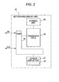
- Fig. 2 illustrates an example of the inner structure of the setting-and-display unit 41.
- the setting-and-display unit 41 includes a storage unit 46, a touch-panel screen display unit 47, a port 48, and a processor 49.
- the port 48 receives the display data signal S9 used for displaying the statistics and the display data signal S12 used for displaying the numbers of stoppages, and transmits and receives signals and data to and from the external devices including the statistic calculator 40 and the arithmetic unit 54 and the internal devices including the screen display unit 47 and the processor 49.
- the storage unit 46 is rewritable, and stores the data regarding the statistics represented by the display data signal S9 and the data regarding the numbers of stoppages represented by the display data signal S12 in association with the sampling numbers.
- the storage unit 46 stores a program for controlling the touch-panel screen display unit 47, a program for graphically displaying the statistics and the number of stoppages, and other necessary software.
- the screen display unit 47 serves as a display device. On the basis of the display data signal S9, the screen display unit 47 graphically displays the statistics in time series along the time axis on the display screen. In addition, on the basis of the display data signal S12, the screen display unit 47 displays the numbers of stoppages of the loom in each sampling period in a visually recognizable manner on the same time axis as the time axis for graphically displaying the statistics. A portion of the display screen of the screen display unit 47 functions as the touch-panel-type setting input unit 37, and the operator can input display requests, various commands, data regarding the sampling number, etc. by touching the display screen. The data regarding the sampling number is transmitted to the statistic calculator 40 and the arithmetic unit 54 through the port 48.
- the setting-and-display unit 41 has a first display function and a second display function regarding the graphical display.
- the first display function the occurrence status of loom stoppages caused by the abnormality regarding the weft yarns 4 and the occurrence status of loom stoppages caused by the abnormality regarding the warp yarns 13 are individually displayed.
- the second display function a section of the display that corresponds to a time period designated on the time axis is magnified and the occurrence status of loom stoppages within the designated time period is displayed for each cause of loom stoppages.
- a list of input history can be shown on the same screen as the magnified display as the information regarding changes in the weaving conditions made in the designated time period.
- the processor 49 includes a central processing unit (CPU), that is, a microprocessor, and controls the input/output operation of the port 48 in accordance with predetermined software stored in the storage unit 46.
- the processor 49 also controls the screen display unit 47 and reads the statistics and the numbers of stoppages of the loom from the storage unit 46 in response to the requests for the screen display input from the setting-and-display unit 41.
- the processor 49 causes the screen display unit 47 to show the graphical display of the statistics and the numbers of stoppages of the loom.
- the statistic calculation unit 38 and the setting-and-display unit 41 calculate the statistics, accumulate the numbers of stoppages, store the thus-obtained statistics and the numbers of stoppages, and graphically displays the stored statistics and numbers of stoppages in time series along the time axis on the display screen.
- These functions may also be provided using a control computer included in the main controller 36 or a dedicated computer, such as a microcomputer, by causing the computer to execute corresponding software processes.
- Figs. 1 and 2 blocks having the respective functions are separately provided.
- the functions may be provided as a single block by using a computer.
- the function of the control device 20 may also be provided as a program by using a computer.
- the functional block of the control device 20 may be replaced by input/output means, storage means, calculating (controlling) means, and displaying means of a computer.
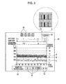
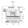
- Figs. 3 and 4 illustrate an example of a display screen 61 for the statistics shown by the screen display unit 47.
- the display screen 61 shown in Fig. 3 displays the statistics, the numbers of stoppages, and the operational information in each sampling period of the weaving process on a single screen.
- the graphical display of the statistics regarding the arrival times of one of the weft yarns 4 in time series along the time axis (hereinafter referred to simply as "display regarding statistics”) is shown as a graph having a horizontal axis (X axis) and a vertical axis (Y axis).
- the unit of the horizontal axis of the graph is a single sampling period.
- the numbers on the scale of the horizontal axis are the numbers of picks, which are proportional to the elapse of time in the weaving operation. Therefore, the horizontal axis can be regarded as the time axis.
- the sampling number (number of picks) corresponding to each sampling period can be set by touching one of selection buttons 43 for selecting "32", "100", and "1000" in a display frame 57 which functions as the setting input unit 37.
- a section corresponding to "1000" is shaded. This means that the sampling number corresponding to each sampling period is set to 1,000 picks.
- the graph shows the weaving period in the past going back from "0" to "-100" by 100 sampling periods along the horizontal axis, and the total number of picks included in the displayed period can be calculated as 100,000 picks.
- the displayed period can be shifted along the time axis as necessary by touching scroll buttons 44 having rectangular marks indicating the left and right directions.
- the graph on the display screen 61 has two vertical axes (Y axes) at the left and right sides.
- the vertical axis at the left side shows the arrival time of one of the weft yarns 4 in terms of rotational angle ⁇ (°).
- the vertical axis at the right side shows the standard deviation.
- line A graphically displays the average of the weft arrival times (weft arrival angles) in each sampling period including 1,000 picks along the time axis using the angles (°) on the scale of the vertical axis at the left side as references.
- the discontinuous bars B graphically display lines obtained by vertically connecting the maximum and minimum weft arrival times (weft arrival angles) in each sampling period including 1,000 picks along the time axis using the angles (°) on the scale of the vertical axis at the left side as references.
- line C shows the standard deviation of the weft arrival times (weft arriving angles) along the time axis using the values on the scale of the vertical axis at the right side as references.
- Yarn supplier marks 45 shown at the top of the display screen 61 indicate yarn types, that is, colors C1 and C2 of the weft yarns 4, and the yarn type of the weft yarn 4 for which the display is currently shown.
- the yarn supplier mark 45 denoted by "1" is shaded. This means that a display corresponding to the color C1 is shown on the screen.
- one of the types (colors) of weft yarns 4 can be selected by touching the corresponding yarn supplier mark 45 on the display screen 61, and accordingly the display can be switched to the graph of weft arrival times for the selected yarn type.
- the screen display unit 47 may be capable of showing a color display in which the lines and bars (A, B, and C) in the graph, the horizontal axis and the vertical axes at the left and right sides, etc. are displayed in different colors or in which the display color is changed for each yarn type. In such a case, visibility can be improved.
- the setting-and-display unit 41 graphically displays the occurrence status of loom stoppages in a section above the graphical display regarding the statistics in accordance with the first display function.
- the information regarding "weft stops”, which are stoppages of the loom due to the abnormality regarding the selected weft yarn 4 and the information regarding "warp stops”, which are stoppages of the loom due to abnormality (breakage) of the warp yarns 13 or the selvage yarns 51, are graphically displayed individually on the horizontal axis.
- the "operational information” is also graphically displayed.
- the number of stoppages of the loom is displayed as the stoppage information such that it can be visually checked whether the number of stoppages is once or plural times, in other words, such that the number of stoppages can be visually recognized.
- the sum of the number of "weft stops” and the number of "warp stops” is not displayed in the example of the display screen, it may also be displayed in a suitable display mode as necessary.
- the display may also be such that only the sum of the numbers is displayed.
- the number of stoppages due to weft insertion failures in the weft insertion operation can be displayed for each of the colors (types) of weft yarns in accordance with the selection of the color.
- the number of stoppages can be checked for each of the yarn types individually.
- each of the displays of "weft stop”, “warp stop”, and “operational information” is shown along an auxiliary axis which is parallel to the time axis (X axis) for the graphical display of the statistics and which has a scale corresponding to the scale on the time axis.
- auxiliary axis which is parallel to the time axis (X axis) for the graphical display of the statistics and which has a scale corresponding to the scale on the time axis.
- the intervals between the points on the scale of time (pick) on the auxiliary axis are the same as the intervals between the points labeled -10, -20, -30, ..., on the scale of time (pick) on the time axis. Therefore, it can be said that the numbers of stoppages ("weft stop” and "warp stop”) are displayed on the same time axis as the time axis for displaying the statistics. If, for example, a space for displaying the numbers of stoppages can be provided along the time axis for displaying the statistics, the numbers of stoppages may also be directly displayed in the space along the time axis for displaying the statistics instead of using the auxiliary axis parallel to the time axis (X axis).
- the display of "weft stop” shows the sum (total number) of the number of times the weft stop signal S2 is output from the first weft feeler 21 and the number of times the weft stop signal S3 is output from the second weft feeler 22.
- the "weft stop” is a stoppage of the loom caused by a weft failure.
- the “weft stop” may also include a stoppage of the loom caused by breakage of a weft yarn to be supplied.
- a yarn breakage sensor (not shown) is disposed on each of the paths of the weft yarns 4 between the yarn suppliers 3 and the measuring-and-storing devices 5, and the number of times a signal is output from each yarn breakage sensor is accumulated together with the numbers of times the signals are output from the first weft feeler 21 and the second weft feeler 22.
- the display of "warp stop” shows the sum (total number) of the number of times the warp stop signal S10 is output from the dropper device 50 and the number of times the warp stop signal S11 is output from the selvage devices 52.
- the stoppage caused by a breakage of the warp yarns (ground warp yarns) 13 is also called a dropper stop.
- the stoppage caused by a breakage of the selvage yarns (leno yarns) 51 is also called a leno breakage stop. In a loom having catch cords, stoppages caused by a breakage of the catch cords are also included in the "warp stop".
- the setting-and-display unit 41 displays the occurrence status of loom stoppages in accordance with the first display function such that the number of stoppages can be visually recognized. Accordingly, if there is an abnormality in the statistics, it can be easily determined whether or not the abnormality is due to the stoppages of the loom. Further, the occurrence status of loom stoppages (number of stoppages) caused by the abnormality regarding the selected weft yarn 4 and the occurrence status of loom stoppages (number of stoppages) caused by the abnormality regarding the warp yarns 13 are individually displayed. Therefore, the operator can accurately determine whether or not the abnormality in the statistics is due to the stoppages of the loom by taking into account the fact that the influence of a stoppage of the loom on the statistics differs depending on the cause of the stoppage.
- the numbers of stoppages of the loom in each sampling period are graphically shown in the form of bars.
- the number of stoppages can be visually recognized as the number of line images in each bar, in other words, the thickness of each bar. More specifically, in the case where the line-shaped graphical images are used as shown in Fig. 3 , if the loom is stopped twice or more, the number of line images corresponding to the number of stoppages are displayed next to each other along the horizontal axis (X axis) without intervals therebetween, so that a bar is formed.
- the case in which the loom is stopped twice or more can be visually distinguished from the case in which the loom is stopped once since a bar with a larger thickness is displayed.
- the above-mentioned line images, each of which corresponds to a single stoppage, may also be disposed next to each other with intervals therebetween in the case where the loom is stopped twice or more. In such a case, the number of stoppages can be recognized as the number of line images.
- the display area provided for each sampling period (1,000 picks) includes three dots along the X axis direction (direction of the time axis), and a graphical image having a single dot in the direction of the horizontal axis (X axis) and 17 dots in the direction of the vertical axis (Y axis) is used as the display (line image) corresponding to a single stoppage. Therefore, in the example shown in Figs. 3 and 4 , the maximum number of stoppages that can be displayed in the display area is three.
- the number of stoppages that can be displayed is limited to three. This is because a situation where the loom is stopped three times or more due to the same cause (weft stop or warp stop) in a single sampling period, which includes 1,000 picks at a maximum, is originally abnormal and hardly occurs in an actual weaving operation. Therefore, the above-mentioned limitation does not cause any serious problem in practical application.
- block-shaped graphical images having the same width as the width of a display area corresponding to a single sampling period can be stacked in the Y-axis direction so that the number of stoppages can be recognized as the height of a bar-shaped image.
- the number of stoppages may be displayed in the form of a numerical character. In such a case, a large number of stoppages can be displayed without reducing the display range along the time axis.
- the display of the number of stoppages may also be such that there is no limit to the number of stoppages that can be displayed as in the above-described case, and a large number of stoppages can be displayed. In such a case, the actual number of stoppages of the loom can be directly displayed.
- the display mode of the number of stoppages in a visually recognizable manner includes both the display mode in which the maximum number of stoppages that can be displayed is limited and the display mode in which there is no limit to the number of stoppages that can be displayed.
- a display section labeled "operational information” is provided between the display section for the graph of the statistics and the display section of "warp stop".
- the display section of "operational information” is provided along the auxiliary time axis which is parallel to the time axis (horizontal axis), and symbols “P", “R”, and “W”, which indicate that the operational information has been changed, are shown on the auxiliary time axis. Meanings of the symbols can be checked by opening a small window which displays an operational-information legend screen 35 as shown in Fig. 4 by touching a legend button 32 shown in Fig. 3 .
- "P" packet sensor
- "R" weft control reset
- “R” shows the information regarding a reset operation performed to return weft-insertion operational conditions (for example, weft-insertion start time) to initial values after the weft-insertion operational conditions are changed in accordance with the arrival angles of each weft yarn 4 in a weft insertion control operation.
- weft-insertion operational conditions for example, weft-insertion start time
- W pattern change
- weft insertion control operation will now be described in detail.
- many looms have an automatic control function for maintaining the arrival time of each weft yarn 4 constant by controlling the weft-insertion operational conditions, such as the weft insertion start time (time at which the stopper pins 8 are removed and/or the ejection start time of the main nozzle units 10) in accordance with the detected arrival angles of the weft yarns 4.
- the arrival time of each weft yarn 4 varies as the weaving operation progresses and the winding diameter of the corresponding yarn supplier 3 decreases.
- the weft-insertion operational conditions are controlled in accordance with a reduction in the winding diameter of each yarn supplier 3.
- the weaving operation progresses and the remaining amount of the weft yarn 4 on one of the yarn suppliers 3 becomes equal to or less than a predetermined amount, or when the weft yarn 4 on one of the yarn suppliers 3 is completely consumed, that yarn supplier 3 is replaced by a new yarn supplier 3.
- the above-described weft-insertion operational conditions which have been changed by the automatic control function, are returned to the initial values. This is the reset operation of the weft insertion control (weft control reset).
- the detection signal S4 from each package sensor 39 is input to the main controller 36, and the main controller 36 performs a loom stop control operation when the detection signal S4 is input. Then, the corresponding yarn supplier 3 is manually replaced with a new yarn supplier 3 by the operator, or is automatically replaced with a new yarn supplier 3. Then, the main controller 36 reactivates the loom and restarts the weaving operation. In the loom in which the yarn supplier 3 is manually replaced by the operator, the reset operation for resetting the weft insertion start time, which has been changed by the above-described automatic control function, to the initial value is performed when the operator operates a reset button.
- the detection signal S4 is input to the weft insertion controller 31, and the reset operation is performed in the weft insertion controller 31.
- the weft insertion start time which is one of the weaving conditions, is changed when the detection signal S4 is generated by one of the package sensors 39. Therefore, it can be considered that the detection signal S4 is included in the weaving-condition change information.
- the detection signal S4 is input not only to the main controller 36 and the weft insertion controller 31 but also to the setting-and-display unit 41.
- two or more yarn suppliers 3 to be successively used may be provided in a so-called pick-tailed state in which the head and tail ends of the respective weft yarns 4 on the yarn suppliers 3 are tied into a knot so that the weft yarns 4 can be continuously supplied.
- a pick-tail sensor (joint sensor) 39a is placed between the adjacent yarn suppliers 3 in the pick-tailed state and is used in place of the package sensor 39.
- the detection signal obtained by the pick-tail sensor 39a is supplied to the main controller 36, etc., instead of the detection signal S4 as the signal indicating the replacement of the corresponding yarn supplier 3.
- the information displayed in the section of the operational information is not limited to those shown in Figs. 3 and 4 , and symbols indicating other information regarding changes in the weaving conditions, such as the weft insertion pattern, the weft density, the rotational speed of the loom, etc., may also be displayed.
- the manner in which the weft yarns 4 travel in the weaving operation is influenced by the changes. This may cause variation in the arrival angles of the weft yarns 4.
- the information regarding the above-mentioned changes can be considered as the information regarding the causes of variation in the manner in which the weft yarns 4 travel.
- the symbols displayed in the section of the operational information are not limited to the alphabets as shown in Figs. 3 and 4 , and may also be other kinds of symbols or character strings which can be recognized.
- the display of the statistics and the display of the operational information are both shown in a single display screen 61 in Figs. 3 and 4
- the display of the operational information may also be displayed in an additional window which is displayed on the display screen 61. Also in this case, it can be said that the statistics and the operational information are displayed on the same screen.
- Figs. 5 to 7 show examples of a magnified display screen 62 corresponding to a specific range in the display screen 61.
- the magnified display screen 62 is displayed by the second display function provided by the setting-and-display unit 41.
- the setting-and-display unit 41 executes the second display function.
- a magnified display of the statistics of the arrival times and the number of stoppages for the designated time period is shown in the magnified display screen 62, as shown in Figs. 5 to 7 .
- the operational information may also be displayed on the magnified display screen 62.
- the magnified display screen 62 is shown so as to replace the previous display screen 61.
- the magnified display screen 62 may also be shown so as to overlap the previous display screen 61 instead of replacing the previous display screen 61, or be shown next to the previous display screen 61.
- the number of stoppages which represents the occurrence status of loom stoppages, is displayed for each cause of stoppage, that is, for each kind of detector (sensor) which detects the cause of stoppage.
- the time period for which the magnified displayed is shown in Figs.
- FIG. 5 to 7 is simply an example, and more detailed display can be obtained if the time period to be shown is reduced and intervals between the points on the scale along the X-axis direction are increased.
- the magnified display screen 62 shown in Fig. 5 can be closed by touching a close button 55 in the lower right section. Accordingly, the display screen 61 shown in Fig. 3 reappears.
- the screen display unit 47 is of a touch panel type, and serves also as the setting input unit 37. Therefore, the operator can set the time period for which the magnified display is to be shown by touching the display screen 61 at a certain position. In this case, the portion of the display screen 61 touched by the operator functions as the setting input unit 37. More specifically, when the operator touches the screen at a middle section of the time period on the time axis for which the magnified display is to be shown, a time point corresponding to the position at which the screen is touched is designated. Then, the magnified display is shown for a time period including predetermined periods before and after the designated time point.
- the time period for which the magnified display is to be shown be set by designating a middle point of the time period as a reference time point.
- the time period for which the magnified display is to be shown may also be set by designating a start point or an end point of the time period as a reference time point.
- the time period instead of setting the time period for which the magnified display is to be shown on the basis of a single designated time point and a predetermined period, the time period may be set by designating two time points as the start point and the end point.
- time points (the middle point, the start point, and the end point) on the basis of which the time period is set be designated by touching the touch-panel display screen, and the time points may also be designated (set) by inputting numerical values, such as pick numbers.
- the above-described designating operation for setting the time period serves also as an operation for showing the magnified display.
- the magnified display is automatically shown when the period setting operation is performed.
- the period setting operation and the magnified-display showing operation may also be performed individually.
- the operator may be allowed to arbitrarily set the magnification ratio.
- the time period for which the magnified display is to be shown may be set on the basis of the time point arbitrarily set by the operator. More specifically, the time period is not limited to the time period that can be arbitrarily set by the operator. Instead, a specific time period, for example, a predetermined period before the current time point can be set on the basis of a set value (time point in the past or number of picks to go back from the current time point) in the setting-and-display unit 41 in advance. In this case, when the magnified-display showing operation is performed without performing the period setting operation, the magnified display for the set time period is shown. Thus, the magnified-display showing operation serves also as the period setting operation.
- a legend button 53 labeled "legend” in an upper right section of the magnified display screen 62 is touched by the operator, a small window for showing the legend is displayed on the same screen, as shown in Fig. 6 . Then, a legend screen 58 on which required information is shown is displayed in the small window. More specifically, the legend screen 58 includes a display frame 59 for the number of stoppages which shows the relationship between display patterns with which the numbers of stoppages are displayed in different ways and the causes of stoppages. In the example shown in Fig.
- the causes of stoppages are indicated by the names (H1 feeler, H2 feeler, dropper, and leno) of detectors (sensors) used for detecting the causes of stoppages.
- the H1 feeler corresponds to the first weft feeler 21 and the sensor 24, and stoppages of the loom caused in response to the detection result obtained by the H1 feeler are also called H1 stops.
- the H2 feeler corresponds to the second weft feeler 22 and the sensor 25, and stoppages of the loom caused in response to the detection result obtained by the H2 feeler are also called H2 stops.
- the legend screen 58 also includes a display frame 60 for the arrival angle showing the relationships between the kinds of lines and bars used in the graphical display of the statistics regarding the arrival angles and the data including the maximum and minimum values, the average, and the standard deviation.
- the legend screen 58 can be closed by touching a close button 56 in the lower right section.
- the magnified display for the time period designated on the time axis can be shown and the occurrence status of stoppages of the loom can be displayed for each of the causes of stoppages individually. Therefore, the operator can easily visually check whether or not there is an abnormality in the statistics and determine the cause of the abnormality in consideration of the causes of stoppages. Therefore, accurate determination can be performed.
- the operator can easily determine that the abnormality in the statistics is due to stoppages of the loom after checking the display contents, it can be determined that the abnormality does not largely affect the future weaving operation and the abnormality can be ignored.
- the cause of the abnormality is not stoppages of the loom.
- it can be assumed that the abnormality is due to an abnormality in the weft yarns 4 or the device.
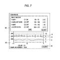
- Fig. 7 shows an example in which the above-described "input history" is displayed as the information regarding changes in the set values of the weaving conditions (in particular, the weft-insertion operational conditions).
- the operator touches an input history button 63 in an upper right section of the magnified display screen 62 shown in Fig. 5 a small window for showing the input history is displayed on the same screen, as shown in Fig. 7 .
- the "input history” regarding changes in the set values of the weaving conditions is displayed on an input-history display screen 64 shown in the small window (weft-insertion operational conditions are shown as an example in Fig. 7 ).
- the display screen 64 information regarding changes in the set values of the weaving conditions made by the operator in the time period for which the magnified display is shown is displayed in order of age such that the oldest information is at the bottom.
- the processes of showing the magnified display and designating the time period are not essential, and are performed as necessary.
- a time period for which the magnified display for the weft yarn 4 of color C1 is shown in Fig. 7 corresponds to a time period between the current time point and 11 sampling periods before the current time point, that is, a time period in which 11,000 picks of the weft yarn 4 of color C1 are inserted.
- the above-mentioned time period corresponds to a weaving time period of the loom in which 44,000 picks of weft yarns 4 are inserted.
- the information of changes in the settings of the weft-insertion operational conditions included in the displayed input history is the information showing changes in the set values of the weft-insertion operational conditions made in a weaving time period of the loom in which 11,000 picks of the weft yarn 4 of color C1 are inserted.
- the input-history display screen 64 is displayed in a window different from the display screen 62 which shows the statistics, and is placed on the magnified display screen 62.
- an additional window is opened on the magnified display screen 62 shown in Fig. 5 , and the input history is shown on the display screen 64 in the additional window as the information of changes in the settings of the weft-insertion operational conditions.
- the display screen 64 may also be displayed next to the magnified display screen 62 on the same screen.
- a time period may be designated on the display screen 61 shown in Fig. 3 or 4 , and the input history in the designated time period may be displayed on the same screen as the display screen 61.
- "C1" and “C2" correspond to color 1 and color 2, respectively, and show the type of the weft yarn 4 for which the setting value is changed among the plurality of types of weft yarns 4 inserted by the multi-color weft insertion device 1.
- "C3", "C4", ... are also displayed.
- "ON” and “OFF” show the ejection start time and the ejection end time, respectively, for the nozzles (the main nozzle units 10 and the sub-nozzles 11).
- "ON” shows the time at which the stopper pin 8 corresponding to the selected weft yarn 4 is moved away from the drum 7 to set the weft yarn 4 in the releasable state
- "OFF” shows the time at which the stopper pin 8 is moved toward the drum 7 to retain the weft yarn 4.
- [-2], [-6], etc., at the rightmost position show the times at which the changes in the settings have been made. More specifically, [-2] shows that the corresponding change has been made two sampling periods before the current time.
- the weaving-condition change information shown in Fig. 7 includes not only the devices for which the set values have been changed and the changes in the set values but also the information (time information) regarding the periods in which the changes have been made or the times at which the changes have been made.
- "SUB 1 C1 ON 65 ⁇ 70 [-2]" means that the ejection start time for the first group of sub-nozzles 11 in the weft insertion operation of the weft yarn 4 of color 1 has been changed from 65° to 70° in terms of crank angle in a sampling period that is two sampling periods before the current time in the statistics regarding color 1.
- the information of changes in the settings of the weft-insertion operational conditions for different types of weft yarns 4 is shown together instead of showing the information regarding each type of weft yarn 4 individually.
- all of the information regarding the changes in the set values of the weft-insertion operational conditions made in the above-described period is displayed as the history.
- the input history to be displayed is not limited to the information of changes in the set values of the weft-insertion operational conditions for the weft insertion operation of the weft yarn 4 for which the statistics are being displayed, and may also include the information of changes in the weft-insertion operational conditions for the weft insertion operation of other types of weft yarns 4.
- the input history to be displayed may also include the information of changes in the settings of the weaving conditions other than the conditions regarding the weft insertion operation (weft-insertion operational conditions).
- the input history to be displayed may also include the weft insertion pattern, the warp shedding pattern, the weft density, the rotational speed of the loom, etc., as the information of changes in the settings of the weaving conditions other than the conditions regarding the weft insertion operation (weft-insertion operational conditions).
- the operator desires to check only the information of changes in the weft-insertion operational conditions for the weft insertion operation of the weft yarn 4 of color C1.
- the information of changes in the settings of the weaving conditions which is to be displayed as the input history may be limited to the information corresponding to the weft insertion operation of the weft yarn 4 for which the statistics are being displayed.
- the display of information of changes in the set values of the weaving conditions for the weft insertion operation of other types of weft yarns 4 may be prohibited.
- specific weaving conditions for example, the ejection times of the main nozzle units 10 and the sub-nozzles 11
- the input history including only the information of changes in the set values of the designated weaving conditions may be displayed.
- the operator designates a time period on the display screen shown in Fig. 3 and displays the magnified display shown in Fig. 5 .
- a time period between the current time point and the time point that is 11 sampling periods before the current time point is shown as the designated time period.
- the operator checks the sampling period in which the abnormality has started.
- the operator operates the input history button 63 on the display screen 62 shown in Fig. 5 to open the input history window corresponding to the designated time period.
- the input-history display screen 64 is displayed.
- the operator can assume that there has been a problem in the operation of changing the set values (in the newly set values).
- the operator can assume that the changes in the set values of the weaving conditions made by the operator are most likely the cause of the abnormality. Therefore, according to the present invention, the cause of the abnormality in the statistics regarding the arrival angles can be quickly and easily determined on the basis of the weaving-condition change information.
- the present invention is not limited to the above-described embodiment, and various modifications are possible.
- the input-history display screen 64 is displayed in a window different from the window in which the display screen 61 for the statistics is displayed, and is placed on the magnified display screen 62 which shows the statistics.
- the present invention is not limited to this as long as the input history and the statistics are displayed on the same screen.
- the input history and the statistics may also be displayed next to each other.
- the state in which two elements are "displayed on the same screen" includes not only the state in which they are superimposed on each other but also the state in which they are displayed next to each other.
- the magnified display for the time period designated on the display screen for the statistics regarding the arrival angles is shown, and the input history corresponding to the time period for which the magnified display is shown is displayed.
- the magnified display can be omitted and the input history corresponding to the designated time period may be displayed on the same screen as the display screen 61 shown in Fig. 3 or 4 .
- the time period for which the magnified display is to be shown is set, and the input history corresponding to the set time period is shown.
- an arbitrarily time point may be designated on the time axis and a set number of changes in the settings may be displayed as the input history in order from the change made at a time point closest to the designated time point.
- the changes in the settings to be displayed may be limited to those made before the designated time point.
- a set number of changes made at times before and after the designated time point may be displayed as the input history.
- the time period is designated using the current time point as the origin.
- the present invention is not limited to this.
- an arbitrarily time period in the past can be designated and the input history for the designated time period can be displayed.
- the process of designating the time period or the specific time point can be omitted.
- a predetermined time period before the current time point or a predetermined number of changes made before the current time point may be displayed as the input history in response to an operation of a history display button.
- the information of changes in the settings to be displayed as the input history for the designated time period includes the information (time information) regarding the time points at which the changes in the settings have been made or the sampling periods in which the changes in the settings have been made.
- the time information may be omitted.
- the information regarding the newly set values may be omitted, and only the information showing the weaving conditions which have been changed and the times at which the weaving conditions have been changed may be displayed. In such a case, the detailed information (set values, detailed times, operators who have made the changes, etc.) may be displayed on another display screen.
- the "input history" regarding the set values of weaving conditions changed by the operator is described as an example of the "information regarding changes in the weaving conditions".
- the "information regarding changes in the weaving conditions” according to the present invention is not limited to this, and other information regarding switching of the weaving conditions is also included.
- the shedding pattern weave structure
- the rotational speed will be changed in the weaving operation.
- the weaving conditions shedding pattern, rotational speed, etc.
- the fact that the switching (change in the weaving conditions) has occurred may be displayed as the information. Therefore, the information regarding the weaving conditions included in the information displayed in the display section of the operational information shown in Figs. 3 and 4 is also included in the "information regarding changes in the weaving conditions" according to the present invention.
- the present invention is not limited to air jet looms, and may also be applied to water jet looms.
- the present invention is not limited to fluid jet looms, and may also be applied to other shuttleless looms, such as rapier looms.
Landscapes
- Engineering & Computer Science (AREA)
- Textile Engineering (AREA)
- Looms (AREA)
Abstract
Description
- The present invention relates to a display method which is used in a display device provided in a loom to graphically display statistics regarding a weft insertion condition along a time axis and which facilitates a determination of the cause of an abnormality when the abnormality occurs in the statistics.
- Japanese Unexamined Patent Application Publication No.
2006-9233 Patent Document 1, a graphical display is shown such that time-series variation in the statistics of weft arrival angles during weft insertion in each predetermined sampling period can be visually recognized. Therefore, it can be determined whether or not an abnormality, such as dispersion, has occurred in the weft arrival angles in each sampling period on the basis of the variation in the statistics. - According to
Patent Document 1, in addition to the graphical display, occurrence status of weft insertion failures may also be displayed along the same time axis as the time axis along which the statistics are displayed, so that causes of an abnormality in the weft insertion operation can be determined. According to the technique ofPatent Document 1, whether or not a weft insertion failure has occurred and the type of the weft insertion failure can be determined for each sampling period. - In the case where there is an abnormality in the statistics regarding weft arrival times, the cause of the abnormality is preferably determined as soon as possible. If, for example, the cause of the abnormality is a root cause, such as an abnormality in a weft yarn or a yarn supplier being used or an abnormality in a weft insertion device, the cause must be eliminated soon since the situation will continue unless the cause is eliminated. Therefore, if there is an abnormality in the statistics as described above, it is preferable that the cause of the abnormality can be easily determined.
- According to the technique described in
Patent Document 1, the occurrence status of weft insertion failures is displayed along the same time axis as the time axis along which the statistics are displayed. Therefore, the relationship between the statistics regarding weft arrival times and the occurrence status of weft insertion failures can be recognized. However, other kinds of information cannot be obtained. Therefore, the cause of the abnormality in the statistics cannot be easily determined and it takes a long time to determine the cause. - Accordingly, an object of the present invention is to provide a display method which is used in a display device of a loom having a display function of graphically displaying statistics regarding a weft insertion condition in the loom along a time axis and which facilitates a determination of the cause of an abnormality when the abnormality occurs in the statistics.
- To achieve the above-described object, according to the present invention, information regarding a change in a weaving condition is displayed on the same screen as a display screen on which the statistics regarding weft arrival times are displayed.
- More specifically, a weft-insertion-condition display method according to the present invention is used in a loom which includes a display device and in which a weft arrival time is detected each time a weft insertion operation is performed. The display device calculates statistics regarding the weft arrival times for each of predetermined sampling periods on the basis of the detected weft arrival times, stores the statistics that are sequentially calculated during a weaving operation in time series, and graphically displays the stored statistics in time series along a time axis. The weft-insertion-condition display method includes the step of displaying information regarding a change in a weaving condition on the same screen as a display screen on which the statistics are displayed.
- The above-mentioned "weaving condition" includes conditions regarding the weft insertion operation and conditions regarding warp yarns and woven cloth. The "weaving condition" regarding the weft insertion operation includes, for example, a weft insertion start time and/or a stopper-pin retracting time at which the stopper pin is retracted in a measuring-and-storing device. The weft insertion start time includes an ejection start time of a main nozzle used in the weft insertion operation, and also includes an ejection start time of an auxiliary main nozzle in the case where the loom includes the auxiliary main nozzle. In addition, the "weaving condition" regarding the weft insertion operation also includes an ejection pressure and an ejection stop time of the main nozzle (and those of the auxiliary main nozzle) and an ejection pressure, an ejection start time, and an ejection stop time of sub-nozzles (each group of sub-nozzles) used in the weft insertion operation. In addition, if the loom includes a weft yarn brake, an activating time of the weft yarn brake is also included in the conditions regarding the weft insertion operation. In addition, the "weaving condition" regarding the warp yarns and the woven cloth includes, for example, a set tension of the warp yarns, a set weaving density of the woven cloth, a shedding pattern, and a rotational speed of the main shaft of the loom.
- As described below, the above-described state in which the information regarding the change in the weaving condition and the statistics are "displayed on the same screen" includes the state in which a display screen of the information regarding the change in the weaving condition (hereinafter also referred to as "weaving-condition change information") is shown in an additional window and is placed on the graphical display which shows the statistics regarding the weft arrival angles (hereinafter also referred to as "statistics display"). In addition, the above-mentioned state also includes the state in which the display screen for the statistics display and the display screen for the weaving-condition change information are shown next to each other on a screen of the display device instead of being superimposed on each other. In addition, the above-described state also includes a display mode in which the statistics display and the weaving-condition change information are displayed together on a single display screen.
- The information regarding the change in the weaving condition includes an input history regarding a change in a setting of the weaving condition. The "input history" may be a list of information regarding changes in set values of weaving conditions made by the operator in a certain time period on the time axis, the information being arranged in order of time on the time axis. The information regarding the changes in the set values include, for example, a change in the set value for the ejection stop time of the main nozzle from 170° to 180°.
- According to the present invention, the information regarding the change in the weaving condition is displayed on the same screen as a screen on which the statistics regarding the arrival times are graphically displayed in time series along the time axis. In the case where there is an abnormality in the statistics shown on the display screen, it can be easily determined whether or not the abnormality has been caused by the change in the weaving condition by referring to the weaving-condition change information.
- More specifically, in the case where an abnormality in the statistics regarding the arrival times starts to occur at a certain time point, the operator tends to consider the cause of the abnormality to be an abnormality regarding the weft yarn being used (switching of yarn supplier) or the weft insertion device. However, it is conceivable that various other causes are to blame. As explained in the description of the related art section, the cause of the abnormality is preferably determined as soon as possible. However, it takes a long time and it is cumbersome to check all the probable causes one by one. In contrast, according to the present invention, the operator can easily check on the display screen whether or not a change in a weaving condition has been made at the time point at which the abnormality in the statistics has occurred. Therefore, the operator can determine whether or not the abnormality in the statistics has occurred due to the change in the weaving condition. As a result, the operator can quickly determine whether the abnormality is due to a hardware problem, such as an abnormality in the weft yarn or the weft insertion device or a software problem, such as a change in a weaving condition.
- In addition, in the case where the input history is displayed such that changes in the settings of the weaving conditions are arranged in order along the time axis, the changes in the settings of the weaving conditions and the changes in the statistics of the arrival times may be directly compared with each other on the time axis. Therefore, the relationship between the changes in the settings of the weaving conditions and the changes in the statistics with respect to time can be observed.
-
-
Fig. 1 is a diagram illustrating the main section of a weft insertion device included in an air jet loom; -
Fig. 2 is a block diagram illustrating an example of a setting-and-display unit according to the present invention; -
Fig. 3 is a diagram illustrating a display example in which statistics, the number of stoppages, and the operational information are displayed on a display screen of the setting-and-display unit; -
Fig. 4 is a diagram illustrating the state in which a window for showing the operational information is displayed on the display screen shown inFig. 3 ; -
Fig. 5 is a diagram illustrating a display screen in which a portion corresponding to a specific period in the display screen shown inFig. 3 is enlarged; -
Fig. 6 is a diagram illustrating the state in which a legend window is displayed on the display screen shown inFig. 5 ; and -
Fig. 7 is a diagram illustrating the state in which an input history window is displayed on the display screen shown inFig. 5 . -
Fig. 1 is a diagram illustrating the main section of an air jet loom as an example of a fluid jet loom to which the present invention is applied. The air jet loom shown inFig. 1 includes, for example, a two-colorweft insertion device 1. In theweft insertion device 1 shown inFig. 1 ,weft yarns 4 of colors C1 and C2 are pulled out from respective yarn suppliers 3 which are supported byholders 2, and are guided to the insides of, for example,rotatable yarn guides 6 included in drum-type measuring-and-storingdevices 5. While theweft yarns 4 are retained bystopper pins 8 on outer peripheral surfaces of drums 7 in a stationary state, therotatable yarn guides 6 rotate so that theweft yarns 4 are wound around the outer peripheral surfaces of the drums 7. Thus, a predetermined length of eachweft yarn 4 which is necessary for a single cycle of weft insertion is stored until theweft yarn 4 is inserted. - The operations of the measuring-and-storing devices 5 (rotating operations of the
rotatable yarn guides 6 and the reciprocal operations of the stopper pins 8) and the operations of weft-insertionmain nozzle units 10, which will be described below, are performed in order of selection of theweft yarns 4 under the control of aweft insertion controller 31 included in acontrol device 20.Package sensors 39 are disposed near the yarn suppliers 3. Eachpackage sensor 39 generates a detection signal S4 when the remaining amount of theweft yarn 4 supplied by the corresponding yarn supplier 3 becomes equal to or less than a predetermined amount. - At a weft-insertion start time, the
stopper pin 8 corresponding to theweft yarn 4 selected by theweft insertion controller 31 is removed from the outer peripheral surface of the corresponding drum 7 by anoperating unit 9. Accordingly, theweft yarn 4 wound around the outer peripheral surface of the drum 7, that is, the predetermined length ofweft yarn 4 which is necessary for a single cycle of weft insertion, is set to a releasable state on the drum 7. Then, the weft-insertionmain nozzle unit 10 corresponding to the selectedweft yarn 4 performs an air ejection operation so that theweft yarn 4, which is inserted through themain nozzle unit 10, is released from the drum 7 and is subjected to weft insertion. In this example, eachmain nozzle unit 10 may be of a two-nozzle type in which an auxiliarymain nozzle 10a and a primarymain nozzle 10b are arranged in series along the direction of theweft yarn 4. - At the set weft-insertion start time, the
main nozzle unit 10 corresponding to the selectedweft yarn 4 starts to ejectcompressed air 12 toward ashed 14 ofwarp yarns 13. The ejection of thecompressed air 12 is continued for a set ejection period, so that the predetermined length ofweft yarn 4 is inserted into theshed 14. Due to this weft insertion operation, theweft yarn 4 travels along a weft traveling path in theshed 14. Thecompressed air 12 is supplied to a commonpressure regulating valve 27 from acompressed air source 26, and the pressure of thecompressed air 12 is adjusted to a pressure suitable for the weft insertion operation by thepressure regulating valve 27. Then, thecompressed air 12 is supplied to the auxiliarymain nozzle 10a and the primarymain nozzle 10b of eachmain nozzle unit 10 through respective electromagnetic on-off valves 28. The electromagnetic on-off valves 28 are operated in order of selection of theweft yarns 4 under the control of theweft insertion controller 31. - As described above, the
weft insertion device 1 shown inFig. 1 is a two-color weft insertion device. If, for example, multi-color weft insertion for two or more colors is to be performed, the yarn suppliers 3, the measuring-and-storingdevices 5, and themain nozzle units 10 are provided for respective colors and the weft yarns are inserted in order of weft selection. In the case where single-color weft insertion is to be performed, a single measuring-and-storingdevice 5 and a singlemain nozzle unit 10 are, of course, provided. - While the inserted
weft yarn 4 travels along the weft traveling path in the shed 14, a plurality of groups ofsub-nozzles 11 are caused to ejectcompressed air 15 toward the weft traveling path in the traveling direction of theweft yarn 4. The sub-nozzles 11 perform simultaneous ejection of thecompressed air 15 or relay ejection thereof in synchronization with the travelling speed of theweft yarn 4. Thus, theweft yarn 4 that travels through the shed 14 is accelerated in the weft insertion direction. Thecompressed air 15 is supplied to apressure regulating valve 29 from the compressedair source 26, and the pressure of thecompressed air 15 is adjusted to a suitable pressure by thepressure regulating valve 29. Then, thecompressed air 15 is supplied to thesub-nozzles 11 of each group through electromagnetic on-offvalves 30 provided for respective groups. In the weft insertion operation, the electromagnetic on-offvalves 30 provided for the respective groups perform simultaneous ejection or relay ejection to accelerate theweft yarn 4 in the weft insertion direction under the control of theweft insertion controller 31. - After the
weft yarn 4 is normally inserted by the ejection operation performed by the correspondingmain nozzle unit 10 and the groups ofsub-nozzles 11, a beating up motion is performed in which theweft yarn 4 is beaten up against a cloth fell 18 of awoven cloth 17 by areed 16. Thus, theweft yarn 4 is woven into the wovencloth 17. Then, theweft yarn 4 is cut by ayarn cutter 19 at a weft insertion side, and is separated from theweft yarn 4 in the primarymain nozzle 10b of themain nozzle unit 10. - A
first weft feeler 21, asensor 24 of thefirst weft feeler 21, asecond weft feeler 22, and asensor 25 of thesecond weft feeler 22 are used for determining whether or not the weft insertion operation is normally performed. Thesensor 24 of thefirst weft feeler 21 is positioned such that thesensor 24 faces the weft traveling path in a region near the edge of the wovencloth 17 at a weft arrival side and such that theweft yarn 4 reaches thesensor 24 if theweft yarn 4 is normally inserted. Thus, thesensor 24 can detect the leading end of theweft yarn 4 if theweft yarn 4 is normally inserted. The detection is performed by comparing a level of a detection signal generated by thesensor 24 in a normal arrival time period (predetermined detection time period) of theweft yarn 4 with a reference signal level. Thus, thesensor 24 of thefirst weft feeler 21 can detect a weft insertion failure (short pick, bent pick, etc.) in which the leading end of the insertedweft yarn 4 does not reach the position of thesensor 24. The detection period is generally set in terms of rotational angle of amain shaft 33. - When the
sensor 24 detects an arrival of theweft yarn 4 within the predetermined detection period, thesensor 24 generates a corresponding output signal. At this time, thefirst weft feeler 21 generates a yarn signal S1 indicating that a normal weft insertion has been performed on the basis of the output signal from thesensor 24, and transmits the yarn signal S1 to amain controller 36 and astatistic calculator 40 in thecontrol device 20. Themain controller 36 continues the operation of the loom (weaving operation) under the condition that the yarn signal S1, which indicates that a normal weft insertion has been performed, is being obtained. Thestatistic calculator 40 and anarithmetic unit 54 form astatistic calculation unit 38. As described in detail below, to display a weft insertion condition, statistics regarding arrival times (arrival angles) of theweft yarn 4 are calculated on the basis of the yarn signal S1 in each of predetermined sampling periods. - If the yarn signal S1 is not generated in the predetermined detection period, that is, if a weft insertion failure occurs and the arrival of the
weft yarn 4 has not been detected by thesensor 24, thefirst weft feeler 21 determines that an abnormality has occurred in the weft insertion operation and outputs a weft stop signal S2. The weft stop signal S2 is transmitted to themain controller 36 and thearithmetic unit 54. - If the
main controller 36 receives the weft stop signal S2, themain controller 36 immediately performs stop control and stops the loom at a predetermined angle. In this case, the loom is stopped due to an abnormality in the weft insertion operation of theweft yarn 4, and the cause of stoppage of the loom corresponds to "weft stop" inFigs. 3 and4 , which will be described below. As described in detail below, to display the status of loom stoppages in a predetermined sampling period in a visually recognizable manner, thearithmetic unit 54 accumulates the number of times the loom is stopped due to the abnormality detected by thefirst weft feeler 21 in the weft insertion operation of theweft yarn 4. - The
sensor 25 of thesecond weft feeler 22 faces the weft traveling path at a position farther from the edge of the wovencloth 17 at the weft arrival side than thesensor 24 in the weft insertion direction. More specifically, thesensor 25 is positioned such that theweft yarn 4 does not reach thesensor 25 if theweft yarn 4 is normally inserted. Thesensor 25 is provided to detect a weft insertion failure such as breakage of theweft yarn 4 and long pick. The detection is performed by comparing a level of a detection signal generated by thesensor 25 at an abnormal arrival time (arrival angle) of theweft yarn 4 in a predetermined detection period with a reference signal level. The predetermined detection period is generally set in terms of rotational angle of themain shaft 33. If thesecond weft feeler 22 receives an output signal from thesensor 25 within the predetermined detection period, thesecond weft feeler 22 determines that an abnormality has occurred in the weft insertion operation and outputs a weft stop signal S3. The weft stop signal S3 is transmitted to themain controller 36 and thearithmetic unit 54. - If the
main controller 36 receives the weft stop signal S3, themain controller 36 immediately stops the loom at a predetermined angle, similar to the case in which the weft stop signal S2 is received. Also in this case, the loom is stopped due to an abnormality in the weft insertion operation of theweft yarn 4, and the cause of stoppage of the loom corresponds to "weft stop" inFigs. 3 and4 , which will be described below. As described in detail below, to display the status of loom stoppages in a predetermined sampling period in a visually recognizable manner, thearithmetic unit 54 accumulates the number of times the loom is stopped due to the abnormality detected by thesecond weft feeler 22 in the weft insertion operation of theweft yarn 4. - The
arithmetic unit 54 of thestatistic calculation unit 38 individually accumulates the number of stoppages due to the abnormality detected by thefirst weft feeler 21 in the weft insertion operation of theweft yarn 4 and the number of stoppages due to the abnormality detected by thesecond weft feeler 22 in the weft insertion operation of theweft yarn 4. In addition, thearithmetic unit 54 calculates the sum of the individually accumulated numbers of stoppages as necessary. - Breakage of the
warp yarns 13 is detected by adropper device 50, and an abnormality, such as breakage, ofselvage yarns 51 used for forming leno structures at the edges of the woven cloth is detected byselvage devices 52 disposed at either side of the woven cloth. Thedropper device 50 includes the same number of droppers as the number ofwarp yarns 13. Eachwarp yarn 13 is inserted through the corresponding dropper and retains the dropper at a predetermined height such that the dropper hangs therefrom. Theselvage devices 52 form the leno structures for restraining the ends of the insertedweft yarn 4 by twisting theselvage yarns 51 each time theweft yarn 4 is inserted. - If one of the
warp yarns 13 breaks in the weaving operation, the dropper at a yarn breakage position falls and an electric closed circuit is formed between that dropper and an electrode (not shown). When the electrically connected state of the closed circuit is detected, thedropper device 50 determines that one of the droppers has fallen and generates a warp stop signal S10. The warp stop signal S10 is transmitted to themain controller 36 and thearithmetic unit 54. - If one of the
selvage yarns 51 breaks in the weaving operation, a selvage yarn sensor (not shown) provided in thecorresponding selvage device 52 detects the breakage of theselvage yarn 51 and generates a warp stop signal S11. The warp stop signal S11 is transmitted to themain controller 36 and thearithmetic unit 54. - When the
main controller 36 receives the warp stop signal S10 or the warp stop signal S11, themain controller 36 immediately stops the loom at a predetermined angle, similar to the case in which the abnormality regarding theweft yarn 4 occurs. In this case, the loom is stopped due to an abnormality regarding thewarp yarns 13 or theselvage yarns 51, and the cause of stoppage of the loom corresponds to "warp stop" inFigs. 3 and4 , which will be described below. As described in detail below, to display the status of loom stoppages in a predetermined sampling period in a visually recognizable manner, thearithmetic unit 54 individually accumulates the number of times the loom is stopped in response to the warp stop signal S10 and the number of times the loom is stopped in response to the warp stop signal S11. In addition, thearithmetic unit 54 calculates the sum of the individually accumulated numbers of stoppages. - The
control device 20 controls the loom in synchronization with the rotation of themain shaft 33 of the loom, displays the weft insertion condition, and performs other necessary control operations. For this purpose, thecontrol device 20 includes theweft insertion controller 31, themain controller 36, thestatistic calculation unit 38, a setting-and-display unit 41, and a weft-selection-signal generator 42. Anencoder 34 is connected to themain shaft 33 to detect the rotational angle of themain shaft 33. In the weaving operation, theencoder 34 generates a signal representing a rotational angle θ of themain shaft 33, and outputs the signal to theweft insertion controller 31, themain controller 36, the weft-selection-signal generator 42, and thestatistic calculator 40. - The
main controller 36 controls the main operation of the loom or the operation of stopping the loom on the basis of the signal representing the rotational angle θ of themain shaft 33. The weft-selection-signal generator 42 determines the amount of rotation of themain shaft 33 from the rotational angle θ and generates a weft selection signal S8 on the basis of the order of weft selection set in advance. The weft-selection-signal generator 42 transmits the weft selection signal S8 to theweft insertion controller 31, thestatistic calculator 40, and thearithmetic unit 54. Theweft insertion controller 31 selects theweft yarn 4 corresponding to the weft selection signal S8 and performs the weft insertion operation of the selectedweft yarn 4 in synchronization with the rotation of themain shaft 33. The weft insertion operation is performed by controlling the operations of the corresponding measuring-and-storingdevice 5 and the correspondingmain nozzle unit 10 in theweft insertion device 1 and the operation of the sub-nozzles 11 in accordance with the rotational angle θ suitable for the selectedweft yarn 4. - The
statistic calculator 40 calculates statistics regarding the arrival times of theweft yarns 4 in each sampling period on the basis of the arrival times detected each time theweft yarns 4 are inserted. For this purpose, thestatistic calculator 40 counts the number of picks (the number of times the weft insertion operation is performed) each time the rotational angle θ reaches a reference rotational angle (0°) on the basis of the signal representing the rotational angle θ. In addition, thestatistic calculator 40 detects the weft arrival angles, that is, the rotational angles θ at the time when theweft yarns 4 arrive, on the basis of the rotational angles θ at which the yarn signal S1 is input in each sampling period which includes a predetermined number of samples (predetermined number of picks). Then, thestatistic calculator 40 calculates the statistics of the weft arrival times for each sampling period. The statistics of the weft arrival times are calculated individually for each of the types of yarns in accordance with the weft selection signal S8. - The thus-calculated statistics include an average of the weft arrival times (average of the weft-arrival rotational angles θ) and one or more of a minimum value (rotational angle θ corresponding to the earliest weft arrival time), a maximum value (rotational angle θ corresponding to the latest weft arrival time), and a standard deviation of the weft arrival times. As described above, theses statistics are calculated for each of the types of yarns.
- The difference between the maximum value and the minimum value indicates the range of dispersion, and the maximum and minimum values indicate the actual values defining the range of dispersion in each sampling period. Since the maximum and minimum values are actual values, they are more useful in making adjustments for the loom than the standard deviation because the range of dispersion can be recognized.
- When the maximum and minimum values are determined, ranges of variations in the maximum and minimum values can be recognized. This is advantageous in making adjustments for the loom, for example, in changing the pressures of the weft insertion nozzles (the
main nozzle units 10 and the sub-nozzles 11). The standard deviation is a numerical measure of dispersion, and corresponds to the degree of dispersion, in other words, the peak height of the binomial distribution. In contrast, the average is calculated as the average of weft arrival angles for a predetermined number of picks, for example 1,000 picks, included in each sampling period. A rough tendency of variation in the weft arrival angle can be recognized from the average of the weft arrival angles. - As described below with reference to
Fig. 2 , the setting-and-display unit 41 functions as a display device for displaying the statistics and weaving-condition change information. The setting-and-display unit 41 includes, for example, a touch-panelsetting input unit 37 for setting the sampling number for each sampling period. In the process of calculating the statistics, the sampling number for each sampling period can be set by selecting one of a plurality of sampling numbers displayed on a setting screen of the setting-and-display unit 41. - In a setting process performed before the weaving operation, an operator selects a suitable sampling number from the sampling numbers displayed on the setting screen of the setting-and-
display unit 41. Here, the sampling number is the number of actually measured weft arrival times based on which the statistics regarding the weft arrival times are calculated for each sampling period. As in the example described below, when the sampling number is set to 1,000 picks, thestatistic calculator 40 calculates the statistics for each sampling period based on the actually measured weft arrival times for 1,000 picks. A storage capacity for storing the statistics is large enough to store at least the number of statistics corresponding to a single package of yarn supplier 3. - The
statistic calculator 40 receives the weft selection signal S8 from the weft-selection-signal generator 42 to calculate the statistics on the basis of data obtained individually for each color of weft yarn. Thestatistic calculator 40 calculates the average of the weft arrival times and one or more of the maximum value of the weft arrival times, the minimum value of the weft arrival times, and the standard deviation of the weft arrival times for each color of weft yarn. Then, thestatistic calculator 40 outputs a display data signal S9 for causing the setting-and-display unit 41 to display the calculated statistics. - The
arithmetic unit 54 receives the weft-selection signal S8 to calculate the number of stoppages of the loom for each color of weft yarn. Thearithmetic unit 54 also receives the weft stop signals S2 and S3 and the warp stop signals S10 and S11. Thearithmetic unit 54 accumulates the number of stoppages of the loom for each cause of stoppage in each sampling period, and generates a display data signal S12 in accordance with the result of the accumulation for each color of weft yarn. The display data signal S12 is transmitted to the setting-and-display unit 41 to display the numbers of stoppages as a display of the occurrence status of loom stoppages. - As described above, the setting-and-
display unit 41 is provided to graphically display the statistics and the weaving-condition change information. The statistic calculation unit 38 (thestatistic calculator 40 and the arithmetic unit 54) receives a command necessary for showing the graphical display from the setting-and-display unit 41 and outputs the display data signals S9 and S12 to the setting-and-display unit 41. The setting-and-display unit 41 is capable of performing two-way communication with theweft insertion controller 31, themain controller 36, and the weft-selection-signal generator 42 to exchange data for setting conditions of statistic calculation and data for setting and changing weaving conditions. The setting-and-display unit 41 is also capable of performing two-way communication with thestatistic calculator 40 and thearithmetic unit 54 to exchange data regarding the graphical display of the statistics and other information. - The setting-and-
display unit 41 receives the display data signals S9 and S12 at the end of each sampling period. On the basis of the data represented by the display data signal S9, the setting-and-display unit 41 stores the statistics which have been successively calculated by thestatistic calculator 40 during the weaving operation in time series. Then, the setting-and-display unit 41 graphically displays the stored statistics in time series along the time axis on the display screen. In addition, on the basis of the data represented by the display data signal S12, the setting-and-display unit 41 displays the occurrence status of loom stoppages, that is, the numbers of stoppages, in each sampling period in a visually recognizable manner on the same time axis as the time axis on which the statistics are graphically displayed. -
Fig. 2 illustrates an example of the inner structure of the setting-and-display unit 41. Referring toFig. 2 , the setting-and-display unit 41 includes astorage unit 46, a touch-panelscreen display unit 47, aport 48, and aprocessor 49. Theport 48 receives the display data signal S9 used for displaying the statistics and the display data signal S12 used for displaying the numbers of stoppages, and transmits and receives signals and data to and from the external devices including thestatistic calculator 40 and thearithmetic unit 54 and the internal devices including thescreen display unit 47 and theprocessor 49. - The
storage unit 46 is rewritable, and stores the data regarding the statistics represented by the display data signal S9 and the data regarding the numbers of stoppages represented by the display data signal S12 in association with the sampling numbers. Thestorage unit 46 stores a program for controlling the touch-panelscreen display unit 47, a program for graphically displaying the statistics and the number of stoppages, and other necessary software. - The
screen display unit 47 serves as a display device. On the basis of the display data signal S9, thescreen display unit 47 graphically displays the statistics in time series along the time axis on the display screen. In addition, on the basis of the display data signal S12, thescreen display unit 47 displays the numbers of stoppages of the loom in each sampling period in a visually recognizable manner on the same time axis as the time axis for graphically displaying the statistics. A portion of the display screen of thescreen display unit 47 functions as the touch-panel-type settinginput unit 37, and the operator can input display requests, various commands, data regarding the sampling number, etc. by touching the display screen. The data regarding the sampling number is transmitted to thestatistic calculator 40 and thearithmetic unit 54 through theport 48. - The setting-and-
display unit 41 has a first display function and a second display function regarding the graphical display. In the first display function, the occurrence status of loom stoppages caused by the abnormality regarding theweft yarns 4 and the occurrence status of loom stoppages caused by the abnormality regarding thewarp yarns 13 are individually displayed. In the second display function, a section of the display that corresponds to a time period designated on the time axis is magnified and the occurrence status of loom stoppages within the designated time period is displayed for each cause of loom stoppages. In addition, in the second display function, a list of input history can be shown on the same screen as the magnified display as the information regarding changes in the weaving conditions made in the designated time period. - The
processor 49 includes a central processing unit (CPU), that is, a microprocessor, and controls the input/output operation of theport 48 in accordance with predetermined software stored in thestorage unit 46. Theprocessor 49 also controls thescreen display unit 47 and reads the statistics and the numbers of stoppages of the loom from thestorage unit 46 in response to the requests for the screen display input from the setting-and-display unit 41. In addition, theprocessor 49 causes thescreen display unit 47 to show the graphical display of the statistics and the numbers of stoppages of the loom. - As described above, the
statistic calculation unit 38 and the setting-and-display unit 41 calculate the statistics, accumulate the numbers of stoppages, store the thus-obtained statistics and the numbers of stoppages, and graphically displays the stored statistics and numbers of stoppages in time series along the time axis on the display screen. These functions may also be provided using a control computer included in themain controller 36 or a dedicated computer, such as a microcomputer, by causing the computer to execute corresponding software processes. - In the structure shown in
Figs. 1 and2 , blocks having the respective functions are separately provided. However, the functions may be provided as a single block by using a computer. In addition, the function of thecontrol device 20 may also be provided as a program by using a computer. Thus, the functional block of thecontrol device 20 may be replaced by input/output means, storage means, calculating (controlling) means, and displaying means of a computer. -
Figs. 3 and4 illustrate an example of adisplay screen 61 for the statistics shown by thescreen display unit 47. Thedisplay screen 61 shown inFig. 3 displays the statistics, the numbers of stoppages, and the operational information in each sampling period of the weaving process on a single screen. The graphical display of the statistics regarding the arrival times of one of theweft yarns 4 in time series along the time axis (hereinafter referred to simply as "display regarding statistics") is shown as a graph having a horizontal axis (X axis) and a vertical axis (Y axis). The unit of the horizontal axis of the graph is a single sampling period. The numbers on the scale of the horizontal axis are the numbers of picks, which are proportional to the elapse of time in the weaving operation. Therefore, the horizontal axis can be regarded as the time axis. - The sampling number (number of picks) corresponding to each sampling period can be set by touching one of
selection buttons 43 for selecting "32", "100", and "1000" in adisplay frame 57 which functions as the settinginput unit 37. InFigs. 3 and4 , a section corresponding to "1000" is shaded. This means that the sampling number corresponding to each sampling period is set to 1,000 picks. - The negative (-) signs on the horizontal axis in
Figs. 3 and4 indicate that the time shown along the horizontal axis is the past, that is, before the current time point (0). Accordingly, the time point indicated as "-10" on the horizontal axis is 10 sampling periods before the current time point (0), that is, 10,000 picks before the current time point since the number of picks can be calculated as 10 x 1,000 (sampling number) = 10,000. Thus, the graph shows the weaving period in the past going back from "0" to "-100" by 100 sampling periods along the horizontal axis, and the total number of picks included in the displayed period can be calculated as 100,000 picks. The displayed period can be shifted along the time axis as necessary by touchingscroll buttons 44 having rectangular marks indicating the left and right directions. - The graph on the
display screen 61 has two vertical axes (Y axes) at the left and right sides. The vertical axis at the left side shows the arrival time of one of theweft yarns 4 in terms of rotational angle θ (°). The vertical axis at the right side shows the standard deviation. - In the graph on the
display screen 61, line A graphically displays the average of the weft arrival times (weft arrival angles) in each sampling period including 1,000 picks along the time axis using the angles (°) on the scale of the vertical axis at the left side as references. In addition, the discontinuous bars B graphically display lines obtained by vertically connecting the maximum and minimum weft arrival times (weft arrival angles) in each sampling period including 1,000 picks along the time axis using the angles (°) on the scale of the vertical axis at the left side as references. In addition, line C shows the standard deviation of the weft arrival times (weft arriving angles) along the time axis using the values on the scale of the vertical axis at the right side as references. - Yarn supplier marks 45 shown at the top of the
display screen 61 indicate yarn types, that is, colors C1 and C2 of theweft yarns 4, and the yarn type of theweft yarn 4 for which the display is currently shown. In thedisplay screen 61, theyarn supplier mark 45 denoted by "1" is shaded. This means that a display corresponding to the color C1 is shown on the screen. In the case where the loom is capable of performing multi-color weft insertion, one of the types (colors) ofweft yarns 4 can be selected by touching the correspondingyarn supplier mark 45 on thedisplay screen 61, and accordingly the display can be switched to the graph of weft arrival times for the selected yarn type. Thescreen display unit 47 may be capable of showing a color display in which the lines and bars (A, B, and C) in the graph, the horizontal axis and the vertical axes at the left and right sides, etc. are displayed in different colors or in which the display color is changed for each yarn type. In such a case, visibility can be improved. - In the example of the
display screen 61 shown inFigs. 3 and4 , the setting-and-display unit 41 graphically displays the occurrence status of loom stoppages in a section above the graphical display regarding the statistics in accordance with the first display function. As the occurrence status of loom stoppages, the information regarding "weft stops", which are stoppages of the loom due to the abnormality regarding the selectedweft yarn 4, and the information regarding "warp stops", which are stoppages of the loom due to abnormality (breakage) of thewarp yarns 13 or theselvage yarns 51, are graphically displayed individually on the horizontal axis. In addition, the "operational information" is also graphically displayed. - In the example shown in
Figs. 3 and4 , the number of stoppages of the loom is displayed as the stoppage information such that it can be visually checked whether the number of stoppages is once or plural times, in other words, such that the number of stoppages can be visually recognized. Although the sum of the number of "weft stops" and the number of "warp stops" (total number of stoppages) is not displayed in the example of the display screen, it may also be displayed in a suitable display mode as necessary. In addition, it is not necessary that the number of "weft stops" and the number "warp stops" be displayed individually, and the display may also be such that only the sum of the numbers is displayed. - In the display of "weft stop", the number of stoppages due to weft insertion failures in the weft insertion operation can be displayed for each of the colors (types) of weft yarns in accordance with the selection of the color. Thus, the number of stoppages can be checked for each of the yarn types individually.
- The display of the stoppage information will be described in more detail. In the
display screen 61, each of the displays of "weft stop", "warp stop", and "operational information" is shown along an auxiliary axis which is parallel to the time axis (X axis) for the graphical display of the statistics and which has a scale corresponding to the scale on the time axis. With regard to the displays of "weft stop" and "warp stop", the number of stoppages that have occurred in each sampling period (1,000 picks) is displayed for each sampling period. The intervals between the points on the scale of time (pick) on the auxiliary axis are the same as the intervals between the points labeled -10, -20, -30, ..., on the scale of time (pick) on the time axis. Therefore, it can be said that the numbers of stoppages ("weft stop" and "warp stop") are displayed on the same time axis as the time axis for displaying the statistics. If, for example, a space for displaying the numbers of stoppages can be provided along the time axis for displaying the statistics, the numbers of stoppages may also be directly displayed in the space along the time axis for displaying the statistics instead of using the auxiliary axis parallel to the time axis (X axis). - The display of "weft stop" shows the sum (total number) of the number of times the weft stop signal S2 is output from the
first weft feeler 21 and the number of times the weft stop signal S3 is output from thesecond weft feeler 22. As described above, the "weft stop" is a stoppage of the loom caused by a weft failure. However, the "weft stop" may also include a stoppage of the loom caused by breakage of a weft yarn to be supplied. In the case where the breakage of a weft yarn to be supplied is included, a yarn breakage sensor (not shown) is disposed on each of the paths of theweft yarns 4 between the yarn suppliers 3 and the measuring-and-storingdevices 5, and the number of times a signal is output from each yarn breakage sensor is accumulated together with the numbers of times the signals are output from thefirst weft feeler 21 and thesecond weft feeler 22. - In addition, the display of "warp stop" shows the sum (total number) of the number of times the warp stop signal S10 is output from the
dropper device 50 and the number of times the warp stop signal S11 is output from theselvage devices 52. The stoppage caused by a breakage of the warp yarns (ground warp yarns) 13 is also called a dropper stop. The stoppage caused by a breakage of the selvage yarns (leno yarns) 51 is also called a leno breakage stop. In a loom having catch cords, stoppages caused by a breakage of the catch cords are also included in the "warp stop". - As described above, the setting-and-
display unit 41 displays the occurrence status of loom stoppages in accordance with the first display function such that the number of stoppages can be visually recognized. Accordingly, if there is an abnormality in the statistics, it can be easily determined whether or not the abnormality is due to the stoppages of the loom. Further, the occurrence status of loom stoppages (number of stoppages) caused by the abnormality regarding the selectedweft yarn 4 and the occurrence status of loom stoppages (number of stoppages) caused by the abnormality regarding thewarp yarns 13 are individually displayed. Therefore, the operator can accurately determine whether or not the abnormality in the statistics is due to the stoppages of the loom by taking into account the fact that the influence of a stoppage of the loom on the statistics differs depending on the cause of the stoppage. - In the display mode of the stoppage information shown in
Figs. 3 and4 , the numbers of stoppages of the loom in each sampling period are graphically shown in the form of bars. As shown in an enlarged view of a circled section provided for additional illustration inFig. 3 , the number of stoppages can be visually recognized as the number of line images in each bar, in other words, the thickness of each bar. More specifically, in the case where the line-shaped graphical images are used as shown inFig. 3 , if the loom is stopped twice or more, the number of line images corresponding to the number of stoppages are displayed next to each other along the horizontal axis (X axis) without intervals therebetween, so that a bar is formed. Therefore, the case in which the loom is stopped twice or more can be visually distinguished from the case in which the loom is stopped once since a bar with a larger thickness is displayed. The above-mentioned line images, each of which corresponds to a single stoppage, may also be disposed next to each other with intervals therebetween in the case where the loom is stopped twice or more. In such a case, the number of stoppages can be recognized as the number of line images. - In the example shown in
Figs. 3 and4 , there is a limit to the number of stoppages that can be displayed within a display area for each sampling period on thedisplay screen 61. More specifically, the number of scale units (dots) provided along the time axis for each sampling period is three, and therefore the number of stoppages that can be displayed is limited to three. Therefore, even if the loom is stopped four times or more, the display of the number of stoppages is the same as that for the case in which the loom is stopped three times. More specifically, the display area provided for each sampling period (1,000 picks) includes three dots along the X axis direction (direction of the time axis), and a graphical image having a single dot in the direction of the horizontal axis (X axis) and 17 dots in the direction of the vertical axis (Y axis) is used as the display (line image) corresponding to a single stoppage. Therefore, in the example shown inFigs. 3 and4 , the maximum number of stoppages that can be displayed in the display area is three. - As described above, in the example shown in
Figs. 3 and4 , the number of stoppages that can be displayed is limited to three. This is because a situation where the loom is stopped three times or more due to the same cause (weft stop or warp stop) in a single sampling period, which includes 1,000 picks at a maximum, is originally abnormal and hardly occurs in an actual weaving operation. Therefore, the above-mentioned limitation does not cause any serious problem in practical application. - With regard to the display of the number of stoppages, block-shaped graphical images having the same width as the width of a display area corresponding to a single sampling period can be stacked in the Y-axis direction so that the number of stoppages can be recognized as the height of a bar-shaped image. Alternatively, the number of stoppages may be displayed in the form of a numerical character. In such a case, a large number of stoppages can be displayed without reducing the display range along the time axis.
- As described above, the display of the number of stoppages may also be such that there is no limit to the number of stoppages that can be displayed as in the above-described case, and a large number of stoppages can be displayed. In such a case, the actual number of stoppages of the loom can be directly displayed. Thus, the display mode of the number of stoppages in a visually recognizable manner includes both the display mode in which the maximum number of stoppages that can be displayed is limited and the display mode in which there is no limit to the number of stoppages that can be displayed.
- With regard to the display of the operational information in the
display screen 61 shown inFigs. 3 and4 , a display section labeled "operational information" is provided between the display section for the graph of the statistics and the display section of "warp stop". The display section of "operational information" is provided along the auxiliary time axis which is parallel to the time axis (horizontal axis), and symbols "P", "R", and "W", which indicate that the operational information has been changed, are shown on the auxiliary time axis. Meanings of the symbols can be checked by opening a small window which displays an operational-information legend screen 35 as shown inFig. 4 by touching alegend button 32 shown inFig. 3 . - Referring to the operational-
information legend screen 35, "P" (package sensor) shows the information regarding a replacement of the yarn suppliers 3, and indicates the time point at which any of the yarn suppliers 3 have been replaced in response to the detection signal S4 from thecorresponding package sensors 39. In addition, "R" (weft control reset) shows the information regarding a reset operation performed to return weft-insertion operational conditions (for example, weft-insertion start time) to initial values after the weft-insertion operational conditions are changed in accordance with the arrival angles of eachweft yarn 4 in a weft insertion control operation. Thus, "R" indicates the time point at which the weft-insertion operational conditions are returned to the initial values. In addition, "W" (pattern change) indicates the time point at which the shedding pattern of thewarp yarns 13 is changed as one of the information regarding changes in the weaving conditions. - The above-described weft insertion control operation will now be described in detail. In general, many looms have an automatic control function for maintaining the arrival time of each
weft yarn 4 constant by controlling the weft-insertion operational conditions, such as the weft insertion start time (time at which the stopper pins 8 are removed and/or the ejection start time of the main nozzle units 10) in accordance with the detected arrival angles of theweft yarns 4. As described above, the arrival time of eachweft yarn 4 varies as the weaving operation progresses and the winding diameter of the corresponding yarn supplier 3 decreases. Therefore, in a loom having the above-mentioned automatic control function, the weft-insertion operational conditions are controlled in accordance with a reduction in the winding diameter of each yarn supplier 3. When the weaving operation progresses and the remaining amount of theweft yarn 4 on one of the yarn suppliers 3 becomes equal to or less than a predetermined amount, or when theweft yarn 4 on one of the yarn suppliers 3 is completely consumed, that yarn supplier 3 is replaced by a new yarn supplier 3. In such a case, the above-described weft-insertion operational conditions, which have been changed by the automatic control function, are returned to the initial values. This is the reset operation of the weft insertion control (weft control reset). - The detection signal S4 from each
package sensor 39 is input to themain controller 36, and themain controller 36 performs a loom stop control operation when the detection signal S4 is input. Then, the corresponding yarn supplier 3 is manually replaced with a new yarn supplier 3 by the operator, or is automatically replaced with a new yarn supplier 3. Then, themain controller 36 reactivates the loom and restarts the weaving operation. In the loom in which the yarn supplier 3 is manually replaced by the operator, the reset operation for resetting the weft insertion start time, which has been changed by the above-described automatic control function, to the initial value is performed when the operator operates a reset button. In the loom in which the yarn supplier 3 is automatically replaced, the detection signal S4 is input to theweft insertion controller 31, and the reset operation is performed in theweft insertion controller 31. The weft insertion start time, which is one of the weaving conditions, is changed when the detection signal S4 is generated by one of thepackage sensors 39. Therefore, it can be considered that the detection signal S4 is included in the weaving-condition change information. The detection signal S4 is input not only to themain controller 36 and theweft insertion controller 31 but also to the setting-and-display unit 41. - As shown by the imaginary lines in
Fig. 1 , two or more yarn suppliers 3 to be successively used may be provided in a so-called pick-tailed state in which the head and tail ends of therespective weft yarns 4 on the yarn suppliers 3 are tied into a knot so that theweft yarns 4 can be continuously supplied. In such a case, a pick-tail sensor (joint sensor) 39a is placed between the adjacent yarn suppliers 3 in the pick-tailed state and is used in place of thepackage sensor 39. The detection signal obtained by the pick-tail sensor 39a is supplied to themain controller 36, etc., instead of the detection signal S4 as the signal indicating the replacement of the corresponding yarn supplier 3. - The information displayed in the section of the operational information is not limited to those shown in
Figs. 3 and4 , and symbols indicating other information regarding changes in the weaving conditions, such as the weft insertion pattern, the weft density, the rotational speed of the loom, etc., may also be displayed. When one of the yarn suppliers 3 is replaced and the weft-insertion operational conditions are reset or when the weaving conditions, such as the weft insertion pattern and the rotational speed of the loom, are changed, the manner in which theweft yarns 4 travel in the weaving operation is influenced by the changes. This may cause variation in the arrival angles of theweft yarns 4. Thus, the information regarding the above-mentioned changes can be considered as the information regarding the causes of variation in the manner in which theweft yarns 4 travel. - The symbols displayed in the section of the operational information are not limited to the alphabets as shown in
Figs. 3 and4 , and may also be other kinds of symbols or character strings which can be recognized. In addition, although the display of the statistics and the display of the operational information are both shown in asingle display screen 61 inFigs. 3 and4 , the display of the operational information may also be displayed in an additional window which is displayed on thedisplay screen 61. Also in this case, it can be said that the statistics and the operational information are displayed on the same screen. -
Figs. 5 to 7 show examples of a magnifieddisplay screen 62 corresponding to a specific range in thedisplay screen 61. The magnifieddisplay screen 62 is displayed by the second display function provided by the setting-and-display unit 41. When the operator designates a certain time period on the time axis in thedisplay screen 61 shown inFigs. 3 and4 , the setting-and-display unit 41 executes the second display function. According to the second display function, a magnified display of the statistics of the arrival times and the number of stoppages for the designated time period is shown in the magnifieddisplay screen 62, as shown inFigs. 5 to 7 . Although the above-described operational information is not displayed in the examples shown inFigs. 5 to 7 , the operational information may also be displayed on the magnifieddisplay screen 62. - In the examples shown in
Figs. 5 to 7 , the magnifieddisplay screen 62 is shown so as to replace theprevious display screen 61. However, the magnifieddisplay screen 62 may also be shown so as to overlap theprevious display screen 61 instead of replacing theprevious display screen 61, or be shown next to theprevious display screen 61. In the magnified display, the number of stoppages, which represents the occurrence status of loom stoppages, is displayed for each cause of stoppage, that is, for each kind of detector (sensor) which detects the cause of stoppage. The time period for which the magnified displayed is shown inFigs. 5 to 7 is simply an example, and more detailed display can be obtained if the time period to be shown is reduced and intervals between the points on the scale along the X-axis direction are increased. The magnifieddisplay screen 62 shown inFig. 5 can be closed by touching aclose button 55 in the lower right section. Accordingly, thedisplay screen 61 shown inFig. 3 reappears. - As described above, the
screen display unit 47 is of a touch panel type, and serves also as the settinginput unit 37. Therefore, the operator can set the time period for which the magnified display is to be shown by touching thedisplay screen 61 at a certain position. In this case, the portion of thedisplay screen 61 touched by the operator functions as the settinginput unit 37. More specifically, when the operator touches the screen at a middle section of the time period on the time axis for which the magnified display is to be shown, a time point corresponding to the position at which the screen is touched is designated. Then, the magnified display is shown for a time period including predetermined periods before and after the designated time point. - However, it is not necessary that the time period for which the magnified display is to be shown be set by designating a middle point of the time period as a reference time point. For example, the time period for which the magnified display is to be shown may also be set by designating a start point or an end point of the time period as a reference time point. In addition, instead of setting the time period for which the magnified display is to be shown on the basis of a single designated time point and a predetermined period, the time period may be set by designating two time points as the start point and the end point. In addition, it is not necessary that the time points (the middle point, the start point, and the end point) on the basis of which the time period is set be designated by touching the touch-panel display screen, and the time points may also be designated (set) by inputting numerical values, such as pick numbers.
- Here, the above-described designating operation (period setting operation) for setting the time period serves also as an operation for showing the magnified display. In other words, the magnified display is automatically shown when the period setting operation is performed. However, the period setting operation and the magnified-display showing operation may also be performed individually. In addition, in the magnified-display showing operation, the operator may be allowed to arbitrarily set the magnification ratio.
- The time period for which the magnified display is to be shown may be set on the basis of the time point arbitrarily set by the operator. More specifically, the time period is not limited to the time period that can be arbitrarily set by the operator. Instead, a specific time period, for example, a predetermined period before the current time point can be set on the basis of a set value (time point in the past or number of picks to go back from the current time point) in the setting-and-
display unit 41 in advance. In this case, when the magnified-display showing operation is performed without performing the period setting operation, the magnified display for the set time period is shown. Thus, the magnified-display showing operation serves also as the period setting operation. - In
Fig. 5 , when alegend button 53 labeled "legend" in an upper right section of the magnifieddisplay screen 62 is touched by the operator, a small window for showing the legend is displayed on the same screen, as shown inFig. 6 . Then, alegend screen 58 on which required information is shown is displayed in the small window. More specifically, thelegend screen 58 includes adisplay frame 59 for the number of stoppages which shows the relationship between display patterns with which the numbers of stoppages are displayed in different ways and the causes of stoppages. In the example shown inFig. 6 , the causes of stoppages are indicated by the names (H1 feeler, H2 feeler, dropper, and leno) of detectors (sensors) used for detecting the causes of stoppages. The H1 feeler corresponds to thefirst weft feeler 21 and thesensor 24, and stoppages of the loom caused in response to the detection result obtained by the H1 feeler are also called H1 stops. In addition, the H2 feeler corresponds to thesecond weft feeler 22 and thesensor 25, and stoppages of the loom caused in response to the detection result obtained by the H2 feeler are also called H2 stops. - The
legend screen 58 also includes adisplay frame 60 for the arrival angle showing the relationships between the kinds of lines and bars used in the graphical display of the statistics regarding the arrival angles and the data including the maximum and minimum values, the average, and the standard deviation. InFig. 6 , thelegend screen 58 can be closed by touching aclose button 56 in the lower right section. - Thus, the magnified display for the time period designated on the time axis can be shown and the occurrence status of stoppages of the loom can be displayed for each of the causes of stoppages individually. Therefore, the operator can easily visually check whether or not there is an abnormality in the statistics and determine the cause of the abnormality in consideration of the causes of stoppages. Therefore, accurate determination can be performed.
- If the operator can easily determine that the abnormality in the statistics is due to stoppages of the loom after checking the display contents, it can be determined that the abnormality does not largely affect the future weaving operation and the abnormality can be ignored. In contrast, if there is an abnormality in the statistics in a certain sampling period but the number of stoppages of the loom is not so large as to affect the statistics, it can be determined that the cause of the abnormality is not stoppages of the loom. In such a case, it can be assumed that the abnormality is due to an abnormality in the
weft yarns 4 or the device. Thus, according to the above-described display, it can be easily determined whether or not the abnormality in the statistics is caused by the stoppages of the loom, and accordingly the cause of the abnormality can be determined in a short time. -
Fig. 7 shows an example in which the above-described "input history" is displayed as the information regarding changes in the set values of the weaving conditions (in particular, the weft-insertion operational conditions). When the operator touches aninput history button 63 in an upper right section of the magnifieddisplay screen 62 shown inFig. 5 , a small window for showing the input history is displayed on the same screen, as shown inFig. 7 . Then, the "input history" regarding changes in the set values of the weaving conditions is displayed on an input-history display screen 64 shown in the small window (weft-insertion operational conditions are shown as an example inFig. 7 ). In thedisplay screen 64, information regarding changes in the set values of the weaving conditions made by the operator in the time period for which the magnified display is shown is displayed in order of age such that the oldest information is at the bottom. As described below, in the display of the weaving-condition change information, the processes of showing the magnified display and designating the time period are not essential, and are performed as necessary. - When, for example, each sampling period includes 1,000 picks as shown at the bottom of the screen in
Fig. 5 , a time period for which the magnified display for theweft yarn 4 of color C1 is shown inFig. 7 corresponds to a time period between the current time point and 11 sampling periods before the current time point, that is, a time period in which 11,000 picks of theweft yarn 4 of color C1 are inserted. In the case where, for example, four types ofweft yarns 4 are evenly selected and inserted, the above-mentioned time period corresponds to a weaving time period of the loom in which 44,000 picks ofweft yarns 4 are inserted. The information of changes in the settings of the weft-insertion operational conditions included in the displayed input history is the information showing changes in the set values of the weft-insertion operational conditions made in a weaving time period of the loom in which 11,000 picks of theweft yarn 4 of color C1 are inserted. - In the example shown in
Fig. 7 , the input-history display screen 64 is displayed in a window different from thedisplay screen 62 which shows the statistics, and is placed on the magnifieddisplay screen 62. Thus, in the example shown inFig. 7 , an additional window is opened on the magnifieddisplay screen 62 shown inFig. 5 , and the input history is shown on thedisplay screen 64 in the additional window as the information of changes in the settings of the weft-insertion operational conditions. Also in this display mode, it can be said that the statistics and the input history are displayed on the same screen. Instead of placing thedisplay screen 64 which shows the input history on the magnifieddisplay screen 62 as described above, thedisplay screen 64 may also be displayed next to the magnifieddisplay screen 62 on the same screen. In addition, a time period may be designated on thedisplay screen 61 shown inFig. 3 or4 , and the input history in the designated time period may be displayed on the same screen as thedisplay screen 61. - The items displayed in the example of the display regarding the input history shown in
Fig. 7 will now be described. In the display screen, "SUB 1", "AUXILIARY MAIN", "MAIN", and "RETAINING PIN" respectively correspond to thesub-nozzles 11 of the first group, the auxiliarymain nozzles 10a, the primarymain nozzles 10b, and the stopper pins 8, which are the devices for which the settings have been changed. The groups ofsub-nozzles 11 include the first group, the second group, ..., in order from the group closest to themain nozzle units 10. - In the display, "C1" and "C2" correspond to
color 1 andcolor 2, respectively, and show the type of theweft yarn 4 for which the setting value is changed among the plurality of types ofweft yarns 4 inserted by the multi-colorweft insertion device 1. In the case where three or moremain nozzle units 10 are used in the weft insertion operation (including the case where theweft yarns 4 of the same type are inserted from two or more of the main nozzle units 10), "C3", "C4", ... are also displayed. - In addition, "ON" and "OFF" show the ejection start time and the ejection end time, respectively, for the nozzles (the
main nozzle units 10 and the sub-nozzles 11). For the stopper pins 8, "ON" shows the time at which thestopper pin 8 corresponding to the selectedweft yarn 4 is moved away from the drum 7 to set theweft yarn 4 in the releasable state and "OFF" shows the time at which thestopper pin 8 is moved toward the drum 7 to retain theweft yarn 4. - In addition, the numerals in "65 → 70", "185 → 190", etc., show the rotational angles θ (crank angles) of the
main shaft 33 of the loom. More specifically, "65 → 70" and "185 → 190" show the cases in which the set value is changed from 65° to 70° and from 185° to 190°, respectively, in terms of crank angle. - In addition, [-2], [-6], etc., at the rightmost position show the times at which the changes in the settings have been made. More specifically, [-2] shows that the corresponding change has been made two sampling periods before the current time. In the case where the information of a plurality of changes is displayed in a historical format, it is necessary to allow the operator to recognize the time points at which the changes have been made. Therefore, the weaving-condition change information shown in
Fig. 7 includes not only the devices for which the set values have been changed and the changes in the set values but also the information (time information) regarding the periods in which the changes have been made or the times at which the changes have been made. - According to the above-described definitions, "
SUB 1 C1 ON 65 → 70 [-2]", for example, means that the ejection start time for the first group ofsub-nozzles 11 in the weft insertion operation of theweft yarn 4 ofcolor 1 has been changed from 65° to 70° in terms of crank angle in a sampling period that is two sampling periods before the current time in thestatistics regarding color 1. - In the display of input history shown in
Fig. 7 , the information of changes in the settings of the weft-insertion operational conditions for different types ofweft yarns 4 is shown together instead of showing the information regarding each type ofweft yarn 4 individually. Thus, all of the information regarding the changes in the set values of the weft-insertion operational conditions made in the above-described period is displayed as the history. The input history to be displayed is not limited to the information of changes in the set values of the weft-insertion operational conditions for the weft insertion operation of theweft yarn 4 for which the statistics are being displayed, and may also include the information of changes in the weft-insertion operational conditions for the weft insertion operation of other types ofweft yarns 4. In addition, the input history to be displayed may also include the information of changes in the settings of the weaving conditions other than the conditions regarding the weft insertion operation (weft-insertion operational conditions). For example, the input history to be displayed may also include the weft insertion pattern, the warp shedding pattern, the weft density, the rotational speed of the loom, etc., as the information of changes in the settings of the weaving conditions other than the conditions regarding the weft insertion operation (weft-insertion operational conditions). - However, if the information of changes in the set values of the weaving conditions which are irrelevant to the displayed statistics is displayed on the input
history display screen 64, there is a risk that the operator will make a wrong decision based on the displayed information. For example, in the case where an abnormality is found in the display of statistics regarding theweft yarn 4 of color C1 and the input history is displayed accordingly, the operator desires to check only the information of changes in the weft-insertion operational conditions for the weft insertion operation of theweft yarn 4 of color C1. However, if many other kinds of information of changes are displayed on the same display screen, it may take a long time for the operator to check the desired information. In addition, in the case where the weft-insertion operational conditions for the weft insertion operation of another type ofweft yarn 4 have been changed in the sampling period in which the abnormality has occurred in the statistics, there is a risk that the operator will wrongly recognize that the information of changes is the information regarding theweft yarn 4 of color C1. To prevent this, the information of changes in the settings of the weaving conditions which is to be displayed as the input history may be limited to the information corresponding to the weft insertion operation of theweft yarn 4 for which the statistics are being displayed. Alternatively, the display of information of changes in the set values of the weaving conditions for the weft insertion operation of other types ofweft yarns 4 may be prohibited. In addition, to reduce the number of displayed items, specific weaving conditions (for example, the ejection times of themain nozzle units 10 and the sub-nozzles 11) may be designated and the input history including only the information of changes in the set values of the designated weaving conditions may be displayed. - In the above-described example, if the operator notices in the weaving operation that there is an abnormality in the statistics regarding arrival angles displayed on the display screen shown in
Fig. 3 , the operator designates a time period on the display screen shown inFig. 3 and displays the magnified display shown inFig. 5 . In the example shown inFig. 5 , a time period between the current time point and the time point that is 11 sampling periods before the current time point is shown as the designated time period. Then, in the magnifieddisplay screen 62 shown inFig. 5 , the operator checks the sampling period in which the abnormality has started. Then, the operator operates theinput history button 63 on thedisplay screen 62 shown inFig. 5 to open the input history window corresponding to the designated time period. As a result, the input-history display screen 64 is displayed. - If there is an abnormality in the statistics regarding the arrival angles and set values of the weaving conditions for the weft insertion operation of the weft yarn for which the statistics are being displayed have been changed in the sampling period in which the abnormality has occurred, the operator can assume that there has been a problem in the operation of changing the set values (in the newly set values). In particular, there may be a case in which there are no other factors, such as loom stoppages which can be checked from the above-described display of the status of loom stoppages or changes in the weaving conditions in response to a change in the weft yarn 4 (yarn supplier 3), which may cause the abnormality. In such a case, the operator can assume that the changes in the set values of the weaving conditions made by the operator are most likely the cause of the abnormality. Therefore, according to the present invention, the cause of the abnormality in the statistics regarding the arrival angles can be quickly and easily determined on the basis of the weaving-condition change information.
- The present invention is not limited to the above-described embodiment, and various modifications are possible. For example, in the above-described embodiment, the input-
history display screen 64 is displayed in a window different from the window in which thedisplay screen 61 for the statistics is displayed, and is placed on the magnifieddisplay screen 62 which shows the statistics. However, the present invention is not limited to this as long as the input history and the statistics are displayed on the same screen. For example, the input history and the statistics may also be displayed next to each other. Thus, according to the present invention, the state in which two elements are "displayed on the same screen" includes not only the state in which they are superimposed on each other but also the state in which they are displayed next to each other. - In the above-described embodiment, the magnified display for the time period designated on the display screen for the statistics regarding the arrival angles is shown, and the input history corresponding to the time period for which the magnified display is shown is displayed. However, the magnified display can be omitted and the input history corresponding to the designated time period may be displayed on the same screen as the
display screen 61 shown inFig. 3 or4 . - In addition, in the above-described embodiment, the time period for which the magnified display is to be shown is set, and the input history corresponding to the set time period is shown. Alternatively, however, an arbitrarily time point may be designated on the time axis and a set number of changes in the settings may be displayed as the input history in order from the change made at a time point closest to the designated time point. In this case, the changes in the settings to be displayed may be limited to those made before the designated time point. Alternatively, a set number of changes made at times before and after the designated time point may be displayed as the input history. With regard to the designation of the time period, in the example shown in the figures, the time period is designated using the current time point as the origin. However, the present invention is not limited to this. For example, an arbitrarily time period in the past can be designated and the input history for the designated time period can be displayed. In addition, the process of designating the time period or the specific time point can be omitted. Instead, a predetermined time period before the current time point or a predetermined number of changes made before the current time point may be displayed as the input history in response to an operation of a history display button.
- In the above-described display of the input history, the information of changes in the settings to be displayed as the input history for the designated time period includes the information (time information) regarding the time points at which the changes in the settings have been made or the sampling periods in which the changes in the settings have been made. However, in the case where the designated time period is narrow, for example, in the case where a single sampling period is designated, the time information may be omitted. In addition, the information regarding the newly set values may be omitted, and only the information showing the weaving conditions which have been changed and the times at which the weaving conditions have been changed may be displayed. In such a case, the detailed information (set values, detailed times, operators who have made the changes, etc.) may be displayed on another display screen.
- In the above-described embodiment, the "input history" regarding the set values of weaving conditions changed by the operator is described as an example of the "information regarding changes in the weaving conditions". However, the "information regarding changes in the weaving conditions" according to the present invention is not limited to this, and other information regarding switching of the weaving conditions is also included. For example, depending on the kind of the texture that is being woven, there is a possibility that the shedding pattern (weave structure) or the rotational speed will be changed in the weaving operation. In the case where the weaving conditions (shedding pattern, rotational speed, etc.) are set to be switched in the weaving operation in advance, the fact that the switching (change in the weaving conditions) has occurred may be displayed as the information. Therefore, the information regarding the weaving conditions included in the information displayed in the display section of the operational information shown in
Figs. 3 and4 is also included in the "information regarding changes in the weaving conditions" according to the present invention. - The present invention is not limited to air jet looms, and may also be applied to water jet looms. In addition, the present invention is not limited to fluid jet looms, and may also be applied to other shuttleless looms, such as rapier looms.
Claims (2)
- A weft-insertion-condition display method for a loom which includes a display device and in which a weft arrival time is detected each time a weft insertion operation is performed, the display device calculating statistics regarding the weft arrival times for each of predetermined sampling periods on the basis of the detected weft arrival times, storing the statistics that are sequentially calculated during a weaving operation in time series, and graphically displaying the stored statistics in time series along a time axis,
wherein the weft-insertion-condition display method is characterized by comprising the step of:displaying information regarding a change in a weaving condition on the same screen as a display screen on which the statistics are displayed. - The weft-insertion-condition display method according to claim 1, wherein the information regarding the change in the weaving condition includes an input history regarding a change in a setting of the weaving condition.
Applications Claiming Priority (1)
| Application Number | Priority Date | Filing Date | Title |
|---|---|---|---|
| JP2008230431A JP5177666B2 (en) | 2008-09-09 | 2008-09-09 | How to display the weft insertion status of the loom |
Publications (2)
| Publication Number | Publication Date |
|---|---|
| EP2161358A1 true EP2161358A1 (en) | 2010-03-10 |
| EP2161358B1 EP2161358B1 (en) | 2011-12-21 |
Family
ID=41217782
Family Applications (1)
| Application Number | Title | Priority Date | Filing Date |
|---|---|---|---|
| EP09010885A Not-in-force EP2161358B1 (en) | 2008-09-09 | 2009-08-25 | Weft-insertion-condition display method for loom |
Country Status (4)
| Country | Link |
|---|---|
| EP (1) | EP2161358B1 (en) |
| JP (1) | JP5177666B2 (en) |
| CN (1) | CN101671909B (en) |
| AT (1) | ATE538231T1 (en) |
Families Citing this family (3)
| Publication number | Priority date | Publication date | Assignee | Title |
|---|---|---|---|---|
| JP5991159B2 (en) * | 2012-11-16 | 2016-09-14 | 株式会社豊田自動織機 | Sub-nozzle arrangement selection device in air jet loom |
| JP6283489B2 (en) * | 2013-02-27 | 2018-02-21 | 津田駒工業株式会社 | Information display method and information display apparatus for loom |
| JP6787141B2 (en) * | 2017-01-13 | 2020-11-18 | 株式会社豊田自動織機 | Weaving diagnostic method for air jet looms and weft diagnostic device for air jet looms |
Citations (4)
| Publication number | Priority date | Publication date | Assignee | Title |
|---|---|---|---|---|
| EP1600538A2 (en) * | 2004-05-24 | 2005-11-30 | Tsudakoma Kogyo Kabushiki Kaisha | Weft-insertion-condition display unit for loom |
| EP1700940A1 (en) * | 2005-03-09 | 2006-09-13 | Tsudakoma Kogyo Kabushiki Kaisha | Information display system for textile machine |
| EP1775359A2 (en) * | 2005-10-17 | 2007-04-18 | Tsudakoma Kogyo Kabushiki Kaisha | Method of determining defect in weft supply package in fluid jet loom |
| EP2088227A2 (en) * | 2008-02-07 | 2009-08-12 | Tsudakoma Kogyo Kabushiki Kaisha | Weft-insertion-condition display method and weft-insertion-condition display apparatus for loom |
Family Cites Families (2)
| Publication number | Priority date | Publication date | Assignee | Title |
|---|---|---|---|---|
| JP3982809B2 (en) * | 2002-09-06 | 2007-09-26 | 津田駒工業株式会社 | Defect display device for looms |
| CN1702215B (en) * | 2004-05-24 | 2011-05-18 | 津田驹工业株式会社 | Weft-insertion-condition display unit for loom |
-
2008
- 2008-09-09 JP JP2008230431A patent/JP5177666B2/en not_active Expired - Fee Related
-
2009
- 2009-08-25 EP EP09010885A patent/EP2161358B1/en not_active Not-in-force
- 2009-08-25 AT AT09010885T patent/ATE538231T1/en active
- 2009-08-31 CN CN200910171395.0A patent/CN101671909B/en not_active Expired - Fee Related
Patent Citations (5)
| Publication number | Priority date | Publication date | Assignee | Title |
|---|---|---|---|---|
| EP1600538A2 (en) * | 2004-05-24 | 2005-11-30 | Tsudakoma Kogyo Kabushiki Kaisha | Weft-insertion-condition display unit for loom |
| JP2006009233A (en) * | 2004-05-24 | 2006-01-12 | Tsudakoma Corp | Weft insertion status display device for loom |
| EP1700940A1 (en) * | 2005-03-09 | 2006-09-13 | Tsudakoma Kogyo Kabushiki Kaisha | Information display system for textile machine |
| EP1775359A2 (en) * | 2005-10-17 | 2007-04-18 | Tsudakoma Kogyo Kabushiki Kaisha | Method of determining defect in weft supply package in fluid jet loom |
| EP2088227A2 (en) * | 2008-02-07 | 2009-08-12 | Tsudakoma Kogyo Kabushiki Kaisha | Weft-insertion-condition display method and weft-insertion-condition display apparatus for loom |
Also Published As
| Publication number | Publication date |
|---|---|
| ATE538231T1 (en) | 2012-01-15 |
| EP2161358B1 (en) | 2011-12-21 |
| JP5177666B2 (en) | 2013-04-03 |
| CN101671909A (en) | 2010-03-17 |
| JP2010065330A (en) | 2010-03-25 |
| CN101671909B (en) | 2012-10-24 |
Similar Documents
| Publication | Publication Date | Title |
|---|---|---|
| EP2733244B1 (en) | Weft-insertion-condition display method in a loom | |
| EP2088227B1 (en) | Weft-insertion-condition display method and weft-insertion-condition display apparatus for loom | |
| EP1878819B1 (en) | Weft inserting apparatus in fluid jet loom | |
| EP2161358B1 (en) | Weft-insertion-condition display method for loom | |
| EP1396562B1 (en) | Method of displaying content of defective weaving of a loom and display unit for displaying content of defective weaving of the loom | |
| JP4953393B2 (en) | Weft insertion status display device for loom | |
| EP2458049B1 (en) | Ejection-period setting method for sub-nozzles in air jet loom | |
| EP1428917B1 (en) | A fluid jet loom suitable to perform a method of calculating timing of weft picking and a method of setting weft inserting condition | |
| JP2013122107A (en) | Method for displaying weft insertion state in loom | |
| EP1600538B1 (en) | Weft-insertion-condition display unit for loom | |
| EP1700940B1 (en) | Information display system for textile machine | |
| EP1775359B1 (en) | Method of determining defect in weft supply package in fluid jet loom | |
| EP2228470B1 (en) | Method for setting weft-insertion conditions in multi-color weft insertion loom | |
| EP2551391A2 (en) | Weaving method and weaving device in a loom | |
| EP1580308B1 (en) | Start control apparatus and start control method for loom | |
| EP2551390A2 (en) | Weaving method and weaving device in a loom | |
| JPH08284045A (en) | Method for carrying out weaving operation of loom and apparatus therefor |
Legal Events
| Date | Code | Title | Description |
|---|---|---|---|
| PUAI | Public reference made under article 153(3) epc to a published international application that has entered the european phase |
Free format text: ORIGINAL CODE: 0009012 |
|
| AK | Designated contracting states |
Kind code of ref document: A1 Designated state(s): AT BE BG CH CY CZ DE DK EE ES FI FR GB GR HR HU IE IS IT LI LT LU LV MC MK MT NL NO PL PT RO SE SI SK SM TR |
|
| AX | Request for extension of the european patent |
Extension state: AL BA RS |
|
| 17P | Request for examination filed |
Effective date: 20100908 |
|
| GRAP | Despatch of communication of intention to grant a patent |
Free format text: ORIGINAL CODE: EPIDOSNIGR1 |
|
| GRAJ | Information related to disapproval of communication of intention to grant by the applicant or resumption of examination proceedings by the epo deleted |
Free format text: ORIGINAL CODE: EPIDOSDIGR1 |
|
| GRAP | Despatch of communication of intention to grant a patent |
Free format text: ORIGINAL CODE: EPIDOSNIGR1 |
|
| GRAS | Grant fee paid |
Free format text: ORIGINAL CODE: EPIDOSNIGR3 |
|
| GRAA | (expected) grant |
Free format text: ORIGINAL CODE: 0009210 |
|
| AK | Designated contracting states |
Kind code of ref document: B1 Designated state(s): AT BE BG CH CY CZ DE DK EE ES FI FR GB GR HR HU IE IS IT LI LT LU LV MC MK MT NL NO PL PT RO SE SI SK SM TR |
|
| REG | Reference to a national code |
Ref country code: GB Ref legal event code: FG4D |
|
| REG | Reference to a national code |
Ref country code: CH Ref legal event code: EP |
|
| REG | Reference to a national code |
Ref country code: AT Ref legal event code: REF Ref document number: 538231 Country of ref document: AT Kind code of ref document: T Effective date: 20120115 |
|
| REG | Reference to a national code |
Ref country code: IE Ref legal event code: FG4D |
|
| REG | Reference to a national code |
Ref country code: DE Ref legal event code: R096 Ref document number: 602009004247 Country of ref document: DE Effective date: 20120308 |
|
| REG | Reference to a national code |
Ref country code: NL Ref legal event code: VDEP Effective date: 20111221 |
|
| PG25 | Lapsed in a contracting state [announced via postgrant information from national office to epo] |
Ref country code: LT Free format text: LAPSE BECAUSE OF FAILURE TO SUBMIT A TRANSLATION OF THE DESCRIPTION OR TO PAY THE FEE WITHIN THE PRESCRIBED TIME-LIMIT Effective date: 20111221 Ref country code: NO Free format text: LAPSE BECAUSE OF FAILURE TO SUBMIT A TRANSLATION OF THE DESCRIPTION OR TO PAY THE FEE WITHIN THE PRESCRIBED TIME-LIMIT Effective date: 20120321 |
|
| LTIE | Lt: invalidation of european patent or patent extension |
Effective date: 20111221 |
|
| PG25 | Lapsed in a contracting state [announced via postgrant information from national office to epo] |
Ref country code: LV Free format text: LAPSE BECAUSE OF FAILURE TO SUBMIT A TRANSLATION OF THE DESCRIPTION OR TO PAY THE FEE WITHIN THE PRESCRIBED TIME-LIMIT Effective date: 20111221 Ref country code: SI Free format text: LAPSE BECAUSE OF FAILURE TO SUBMIT A TRANSLATION OF THE DESCRIPTION OR TO PAY THE FEE WITHIN THE PRESCRIBED TIME-LIMIT Effective date: 20111221 Ref country code: HR Free format text: LAPSE BECAUSE OF FAILURE TO SUBMIT A TRANSLATION OF THE DESCRIPTION OR TO PAY THE FEE WITHIN THE PRESCRIBED TIME-LIMIT Effective date: 20111221 Ref country code: SE Free format text: LAPSE BECAUSE OF FAILURE TO SUBMIT A TRANSLATION OF THE DESCRIPTION OR TO PAY THE FEE WITHIN THE PRESCRIBED TIME-LIMIT Effective date: 20111221 Ref country code: GR Free format text: LAPSE BECAUSE OF FAILURE TO SUBMIT A TRANSLATION OF THE DESCRIPTION OR TO PAY THE FEE WITHIN THE PRESCRIBED TIME-LIMIT Effective date: 20120322 Ref country code: NL Free format text: LAPSE BECAUSE OF FAILURE TO SUBMIT A TRANSLATION OF THE DESCRIPTION OR TO PAY THE FEE WITHIN THE PRESCRIBED TIME-LIMIT Effective date: 20111221 |
|
| PG25 | Lapsed in a contracting state [announced via postgrant information from national office to epo] |
Ref country code: CY Free format text: LAPSE BECAUSE OF FAILURE TO SUBMIT A TRANSLATION OF THE DESCRIPTION OR TO PAY THE FEE WITHIN THE PRESCRIBED TIME-LIMIT Effective date: 20111221 |
|
| PG25 | Lapsed in a contracting state [announced via postgrant information from national office to epo] |
Ref country code: SK Free format text: LAPSE BECAUSE OF FAILURE TO SUBMIT A TRANSLATION OF THE DESCRIPTION OR TO PAY THE FEE WITHIN THE PRESCRIBED TIME-LIMIT Effective date: 20111221 Ref country code: EE Free format text: LAPSE BECAUSE OF FAILURE TO SUBMIT A TRANSLATION OF THE DESCRIPTION OR TO PAY THE FEE WITHIN THE PRESCRIBED TIME-LIMIT Effective date: 20111221 Ref country code: BG Free format text: LAPSE BECAUSE OF FAILURE TO SUBMIT A TRANSLATION OF THE DESCRIPTION OR TO PAY THE FEE WITHIN THE PRESCRIBED TIME-LIMIT Effective date: 20120321 Ref country code: IS Free format text: LAPSE BECAUSE OF FAILURE TO SUBMIT A TRANSLATION OF THE DESCRIPTION OR TO PAY THE FEE WITHIN THE PRESCRIBED TIME-LIMIT Effective date: 20120421 Ref country code: CZ Free format text: LAPSE BECAUSE OF FAILURE TO SUBMIT A TRANSLATION OF THE DESCRIPTION OR TO PAY THE FEE WITHIN THE PRESCRIBED TIME-LIMIT Effective date: 20111221 |
|
| PG25 | Lapsed in a contracting state [announced via postgrant information from national office to epo] |
Ref country code: PT Free format text: LAPSE BECAUSE OF FAILURE TO SUBMIT A TRANSLATION OF THE DESCRIPTION OR TO PAY THE FEE WITHIN THE PRESCRIBED TIME-LIMIT Effective date: 20120423 Ref country code: RO Free format text: LAPSE BECAUSE OF FAILURE TO SUBMIT A TRANSLATION OF THE DESCRIPTION OR TO PAY THE FEE WITHIN THE PRESCRIBED TIME-LIMIT Effective date: 20111221 Ref country code: PL Free format text: LAPSE BECAUSE OF FAILURE TO SUBMIT A TRANSLATION OF THE DESCRIPTION OR TO PAY THE FEE WITHIN THE PRESCRIBED TIME-LIMIT Effective date: 20111221 |
|
| REG | Reference to a national code |
Ref country code: AT Ref legal event code: MK05 Ref document number: 538231 Country of ref document: AT Kind code of ref document: T Effective date: 20111221 |
|
| PLBE | No opposition filed within time limit |
Free format text: ORIGINAL CODE: 0009261 |
|
| STAA | Information on the status of an ep patent application or granted ep patent |
Free format text: STATUS: NO OPPOSITION FILED WITHIN TIME LIMIT |
|
| PG25 | Lapsed in a contracting state [announced via postgrant information from national office to epo] |
Ref country code: DK Free format text: LAPSE BECAUSE OF FAILURE TO SUBMIT A TRANSLATION OF THE DESCRIPTION OR TO PAY THE FEE WITHIN THE PRESCRIBED TIME-LIMIT Effective date: 20111221 |
|
| 26N | No opposition filed |
Effective date: 20120924 |
|
| REG | Reference to a national code |
Ref country code: DE Ref legal event code: R097 Ref document number: 602009004247 Country of ref document: DE Effective date: 20120924 |
|
| PG25 | Lapsed in a contracting state [announced via postgrant information from national office to epo] |
Ref country code: AT Free format text: LAPSE BECAUSE OF FAILURE TO SUBMIT A TRANSLATION OF THE DESCRIPTION OR TO PAY THE FEE WITHIN THE PRESCRIBED TIME-LIMIT Effective date: 20111221 |
|
| PG25 | Lapsed in a contracting state [announced via postgrant information from national office to epo] |
Ref country code: MC Free format text: LAPSE BECAUSE OF NON-PAYMENT OF DUE FEES Effective date: 20120831 |
|
| PG25 | Lapsed in a contracting state [announced via postgrant information from national office to epo] |
Ref country code: ES Free format text: LAPSE BECAUSE OF FAILURE TO SUBMIT A TRANSLATION OF THE DESCRIPTION OR TO PAY THE FEE WITHIN THE PRESCRIBED TIME-LIMIT Effective date: 20120401 |
|
| REG | Reference to a national code |
Ref country code: FR Ref legal event code: ST Effective date: 20130430 |
|
| REG | Reference to a national code |
Ref country code: IE Ref legal event code: MM4A |
|
| PG25 | Lapsed in a contracting state [announced via postgrant information from national office to epo] |
Ref country code: FI Free format text: LAPSE BECAUSE OF FAILURE TO SUBMIT A TRANSLATION OF THE DESCRIPTION OR TO PAY THE FEE WITHIN THE PRESCRIBED TIME-LIMIT Effective date: 20111221 |
|
| PG25 | Lapsed in a contracting state [announced via postgrant information from national office to epo] |
Ref country code: IE Free format text: LAPSE BECAUSE OF NON-PAYMENT OF DUE FEES Effective date: 20120825 |
|
| PG25 | Lapsed in a contracting state [announced via postgrant information from national office to epo] |
Ref country code: FR Free format text: LAPSE BECAUSE OF NON-PAYMENT OF DUE FEES Effective date: 20120831 |
|
| PG25 | Lapsed in a contracting state [announced via postgrant information from national office to epo] |
Ref country code: MT Free format text: LAPSE BECAUSE OF FAILURE TO SUBMIT A TRANSLATION OF THE DESCRIPTION OR TO PAY THE FEE WITHIN THE PRESCRIBED TIME-LIMIT Effective date: 20111221 |
|
| REG | Reference to a national code |
Ref country code: CH Ref legal event code: PL |
|
| GBPC | Gb: european patent ceased through non-payment of renewal fee |
Effective date: 20130825 |
|
| PG25 | Lapsed in a contracting state [announced via postgrant information from national office to epo] |
Ref country code: LI Free format text: LAPSE BECAUSE OF NON-PAYMENT OF DUE FEES Effective date: 20130831 Ref country code: CH Free format text: LAPSE BECAUSE OF NON-PAYMENT OF DUE FEES Effective date: 20130831 Ref country code: TR Free format text: LAPSE BECAUSE OF FAILURE TO SUBMIT A TRANSLATION OF THE DESCRIPTION OR TO PAY THE FEE WITHIN THE PRESCRIBED TIME-LIMIT Effective date: 20111221 |
|
| PG25 | Lapsed in a contracting state [announced via postgrant information from national office to epo] |
Ref country code: SM Free format text: LAPSE BECAUSE OF FAILURE TO SUBMIT A TRANSLATION OF THE DESCRIPTION OR TO PAY THE FEE WITHIN THE PRESCRIBED TIME-LIMIT Effective date: 20111221 Ref country code: LU Free format text: LAPSE BECAUSE OF NON-PAYMENT OF DUE FEES Effective date: 20120825 |
|
| PG25 | Lapsed in a contracting state [announced via postgrant information from national office to epo] |
Ref country code: GB Free format text: LAPSE BECAUSE OF NON-PAYMENT OF DUE FEES Effective date: 20130825 Ref country code: HU Free format text: LAPSE BECAUSE OF FAILURE TO SUBMIT A TRANSLATION OF THE DESCRIPTION OR TO PAY THE FEE WITHIN THE PRESCRIBED TIME-LIMIT Effective date: 20090825 |
|
| PG25 | Lapsed in a contracting state [announced via postgrant information from national office to epo] |
Ref country code: MK Free format text: LAPSE BECAUSE OF FAILURE TO SUBMIT A TRANSLATION OF THE DESCRIPTION OR TO PAY THE FEE WITHIN THE PRESCRIBED TIME-LIMIT Effective date: 20111221 |
|
| PGFP | Annual fee paid to national office [announced via postgrant information from national office to epo] |
Ref country code: IT Payment date: 20220712 Year of fee payment: 14 Ref country code: DE Payment date: 20220705 Year of fee payment: 14 |
|
| PGFP | Annual fee paid to national office [announced via postgrant information from national office to epo] |
Ref country code: BE Payment date: 20220718 Year of fee payment: 14 |
|
| REG | Reference to a national code |
Ref country code: DE Ref legal event code: R119 Ref document number: 602009004247 Country of ref document: DE |
|
| REG | Reference to a national code |
Ref country code: BE Ref legal event code: MM Effective date: 20230831 |
|
| PG25 | Lapsed in a contracting state [announced via postgrant information from national office to epo] |
Ref country code: IT Free format text: LAPSE BECAUSE OF NON-PAYMENT OF DUE FEES Effective date: 20230825 Ref country code: DE Free format text: LAPSE BECAUSE OF NON-PAYMENT OF DUE FEES Effective date: 20240301 |
|
| PG25 | Lapsed in a contracting state [announced via postgrant information from national office to epo] |
Ref country code: BE Free format text: LAPSE BECAUSE OF NON-PAYMENT OF DUE FEES Effective date: 20230831 |