EP2161353A2 - Coating method using plasma shock wave and method for manufacturing coated substance - Google Patents
Coating method using plasma shock wave and method for manufacturing coated substance Download PDFInfo
- Publication number
- EP2161353A2 EP2161353A2 EP09169799A EP09169799A EP2161353A2 EP 2161353 A2 EP2161353 A2 EP 2161353A2 EP 09169799 A EP09169799 A EP 09169799A EP 09169799 A EP09169799 A EP 09169799A EP 2161353 A2 EP2161353 A2 EP 2161353A2
- Authority
- EP
- European Patent Office
- Prior art keywords
- powders
- mixed layer
- powder
- coating
- plasma
- Prior art date
- Legal status (The legal status is an assumption and is not a legal conclusion. Google has not performed a legal analysis and makes no representation as to the accuracy of the status listed.)
- Granted
Links
Images


Classifications
-
- C—CHEMISTRY; METALLURGY
- C23—COATING METALLIC MATERIAL; COATING MATERIAL WITH METALLIC MATERIAL; CHEMICAL SURFACE TREATMENT; DIFFUSION TREATMENT OF METALLIC MATERIAL; COATING BY VACUUM EVAPORATION, BY SPUTTERING, BY ION IMPLANTATION OR BY CHEMICAL VAPOUR DEPOSITION, IN GENERAL; INHIBITING CORROSION OF METALLIC MATERIAL OR INCRUSTATION IN GENERAL
- C23C—COATING METALLIC MATERIAL; COATING MATERIAL WITH METALLIC MATERIAL; SURFACE TREATMENT OF METALLIC MATERIAL BY DIFFUSION INTO THE SURFACE, BY CHEMICAL CONVERSION OR SUBSTITUTION; COATING BY VACUUM EVAPORATION, BY SPUTTERING, BY ION IMPLANTATION OR BY CHEMICAL VAPOUR DEPOSITION, IN GENERAL
- C23C26/00—Coating not provided for in groups C23C2/00 - C23C24/00
-
- B—PERFORMING OPERATIONS; TRANSPORTING
- B23—MACHINE TOOLS; METAL-WORKING NOT OTHERWISE PROVIDED FOR
- B23K—SOLDERING OR UNSOLDERING; WELDING; CLADDING OR PLATING BY SOLDERING OR WELDING; CUTTING BY APPLYING HEAT LOCALLY, e.g. FLAME CUTTING; WORKING BY LASER BEAM
- B23K26/00—Working by laser beam, e.g. welding, cutting or boring
- B23K26/20—Bonding
- B23K26/32—Bonding taking account of the properties of the material involved
-
- B—PERFORMING OPERATIONS; TRANSPORTING
- B23—MACHINE TOOLS; METAL-WORKING NOT OTHERWISE PROVIDED FOR
- B23K—SOLDERING OR UNSOLDERING; WELDING; CLADDING OR PLATING BY SOLDERING OR WELDING; CUTTING BY APPLYING HEAT LOCALLY, e.g. FLAME CUTTING; WORKING BY LASER BEAM
- B23K26/00—Working by laser beam, e.g. welding, cutting or boring
- B23K26/34—Laser welding for purposes other than joining
-
- B—PERFORMING OPERATIONS; TRANSPORTING
- B23—MACHINE TOOLS; METAL-WORKING NOT OTHERWISE PROVIDED FOR
- B23K—SOLDERING OR UNSOLDERING; WELDING; CLADDING OR PLATING BY SOLDERING OR WELDING; CUTTING BY APPLYING HEAT LOCALLY, e.g. FLAME CUTTING; WORKING BY LASER BEAM
- B23K35/00—Rods, electrodes, materials, or media, for use in soldering, welding, or cutting
- B23K35/02—Rods, electrodes, materials, or media, for use in soldering, welding, or cutting characterised by mechanical features, e.g. shape
- B23K35/0222—Rods, electrodes, materials, or media, for use in soldering, welding, or cutting characterised by mechanical features, e.g. shape for use in soldering, brazing
- B23K35/0244—Powders, particles or spheres; Preforms made therefrom
-
- B—PERFORMING OPERATIONS; TRANSPORTING
- B23—MACHINE TOOLS; METAL-WORKING NOT OTHERWISE PROVIDED FOR
- B23K—SOLDERING OR UNSOLDERING; WELDING; CLADDING OR PLATING BY SOLDERING OR WELDING; CUTTING BY APPLYING HEAT LOCALLY, e.g. FLAME CUTTING; WORKING BY LASER BEAM
- B23K35/00—Rods, electrodes, materials, or media, for use in soldering, welding, or cutting
- B23K35/22—Rods, electrodes, materials, or media, for use in soldering, welding, or cutting characterised by the composition or nature of the material
- B23K35/36—Selection of non-metallic compositions, e.g. coatings, fluxes; Selection of soldering or welding materials, conjoint with selection of non-metallic compositions, both selections being of interest
- B23K35/3612—Selection of non-metallic compositions, e.g. coatings, fluxes; Selection of soldering or welding materials, conjoint with selection of non-metallic compositions, both selections being of interest with organic compounds as principal constituents
- B23K35/3613—Polymers, e.g. resins
-
- C—CHEMISTRY; METALLURGY
- C23—COATING METALLIC MATERIAL; COATING MATERIAL WITH METALLIC MATERIAL; CHEMICAL SURFACE TREATMENT; DIFFUSION TREATMENT OF METALLIC MATERIAL; COATING BY VACUUM EVAPORATION, BY SPUTTERING, BY ION IMPLANTATION OR BY CHEMICAL VAPOUR DEPOSITION, IN GENERAL; INHIBITING CORROSION OF METALLIC MATERIAL OR INCRUSTATION IN GENERAL
- C23C—COATING METALLIC MATERIAL; COATING MATERIAL WITH METALLIC MATERIAL; SURFACE TREATMENT OF METALLIC MATERIAL BY DIFFUSION INTO THE SURFACE, BY CHEMICAL CONVERSION OR SUBSTITUTION; COATING BY VACUUM EVAPORATION, BY SPUTTERING, BY ION IMPLANTATION OR BY CHEMICAL VAPOUR DEPOSITION, IN GENERAL
- C23C24/00—Coating starting from inorganic powder
- C23C24/02—Coating starting from inorganic powder by application of pressure only
- C23C24/04—Impact or kinetic deposition of particles
-
- C—CHEMISTRY; METALLURGY
- C23—COATING METALLIC MATERIAL; COATING MATERIAL WITH METALLIC MATERIAL; CHEMICAL SURFACE TREATMENT; DIFFUSION TREATMENT OF METALLIC MATERIAL; COATING BY VACUUM EVAPORATION, BY SPUTTERING, BY ION IMPLANTATION OR BY CHEMICAL VAPOUR DEPOSITION, IN GENERAL; INHIBITING CORROSION OF METALLIC MATERIAL OR INCRUSTATION IN GENERAL
- C23C—COATING METALLIC MATERIAL; COATING MATERIAL WITH METALLIC MATERIAL; SURFACE TREATMENT OF METALLIC MATERIAL BY DIFFUSION INTO THE SURFACE, BY CHEMICAL CONVERSION OR SUBSTITUTION; COATING BY VACUUM EVAPORATION, BY SPUTTERING, BY ION IMPLANTATION OR BY CHEMICAL VAPOUR DEPOSITION, IN GENERAL
- C23C24/00—Coating starting from inorganic powder
- C23C24/08—Coating starting from inorganic powder by application of heat or pressure and heat
- C23C24/10—Coating starting from inorganic powder by application of heat or pressure and heat with intermediate formation of a liquid phase in the layer
-
- C—CHEMISTRY; METALLURGY
- C23—COATING METALLIC MATERIAL; COATING MATERIAL WITH METALLIC MATERIAL; CHEMICAL SURFACE TREATMENT; DIFFUSION TREATMENT OF METALLIC MATERIAL; COATING BY VACUUM EVAPORATION, BY SPUTTERING, BY ION IMPLANTATION OR BY CHEMICAL VAPOUR DEPOSITION, IN GENERAL; INHIBITING CORROSION OF METALLIC MATERIAL OR INCRUSTATION IN GENERAL
- C23C—COATING METALLIC MATERIAL; COATING MATERIAL WITH METALLIC MATERIAL; SURFACE TREATMENT OF METALLIC MATERIAL BY DIFFUSION INTO THE SURFACE, BY CHEMICAL CONVERSION OR SUBSTITUTION; COATING BY VACUUM EVAPORATION, BY SPUTTERING, BY ION IMPLANTATION OR BY CHEMICAL VAPOUR DEPOSITION, IN GENERAL
- C23C4/00—Coating by spraying the coating material in the molten state, e.g. by flame, plasma or electric discharge
- C23C4/18—After-treatment
-
- B—PERFORMING OPERATIONS; TRANSPORTING
- B23—MACHINE TOOLS; METAL-WORKING NOT OTHERWISE PROVIDED FOR
- B23K—SOLDERING OR UNSOLDERING; WELDING; CLADDING OR PLATING BY SOLDERING OR WELDING; CUTTING BY APPLYING HEAT LOCALLY, e.g. FLAME CUTTING; WORKING BY LASER BEAM
- B23K2103/00—Materials to be soldered, welded or cut
- B23K2103/50—Inorganic material, e.g. metals, not provided for in B23K2103/02 – B23K2103/26
- B23K2103/52—Ceramics
-
- Y—GENERAL TAGGING OF NEW TECHNOLOGICAL DEVELOPMENTS; GENERAL TAGGING OF CROSS-SECTIONAL TECHNOLOGIES SPANNING OVER SEVERAL SECTIONS OF THE IPC; TECHNICAL SUBJECTS COVERED BY FORMER USPC CROSS-REFERENCE ART COLLECTIONS [XRACs] AND DIGESTS
- Y10—TECHNICAL SUBJECTS COVERED BY FORMER USPC
- Y10T—TECHNICAL SUBJECTS COVERED BY FORMER US CLASSIFICATION
- Y10T428/00—Stock material or miscellaneous articles
- Y10T428/24—Structurally defined web or sheet [e.g., overall dimension, etc.]
- Y10T428/24355—Continuous and nonuniform or irregular surface on layer or component [e.g., roofing, etc.]
- Y10T428/24372—Particulate matter
- Y10T428/24405—Polymer or resin [e.g., natural or synthetic rubber, etc.]
-
- Y—GENERAL TAGGING OF NEW TECHNOLOGICAL DEVELOPMENTS; GENERAL TAGGING OF CROSS-SECTIONAL TECHNOLOGIES SPANNING OVER SEVERAL SECTIONS OF THE IPC; TECHNICAL SUBJECTS COVERED BY FORMER USPC CROSS-REFERENCE ART COLLECTIONS [XRACs] AND DIGESTS
- Y10—TECHNICAL SUBJECTS COVERED BY FORMER USPC
- Y10T—TECHNICAL SUBJECTS COVERED BY FORMER US CLASSIFICATION
- Y10T428/00—Stock material or miscellaneous articles
- Y10T428/24—Structurally defined web or sheet [e.g., overall dimension, etc.]
- Y10T428/24355—Continuous and nonuniform or irregular surface on layer or component [e.g., roofing, etc.]
- Y10T428/24372—Particulate matter
- Y10T428/24421—Silicon containing
-
- Y—GENERAL TAGGING OF NEW TECHNOLOGICAL DEVELOPMENTS; GENERAL TAGGING OF CROSS-SECTIONAL TECHNOLOGIES SPANNING OVER SEVERAL SECTIONS OF THE IPC; TECHNICAL SUBJECTS COVERED BY FORMER USPC CROSS-REFERENCE ART COLLECTIONS [XRACs] AND DIGESTS
- Y10—TECHNICAL SUBJECTS COVERED BY FORMER USPC
- Y10T—TECHNICAL SUBJECTS COVERED BY FORMER US CLASSIFICATION
- Y10T428/00—Stock material or miscellaneous articles
- Y10T428/29—Coated or structually defined flake, particle, cell, strand, strand portion, rod, filament, macroscopic fiber or mass thereof
- Y10T428/2913—Rod, strand, filament or fiber
- Y10T428/2933—Coated or with bond, impregnation or core
- Y10T428/294—Coated or with bond, impregnation or core including metal or compound thereof [excluding glass, ceramic and asbestos]
Definitions
- the present invention relates to a coating method using a plasma shock wave and a method for manufacturing a coated substance.
- a laser peening method is used as a method using a plasma shock wave for reforming surfaces of such as machinery parts by applying residual stress into the surfaces.
- Processing that uses the laser peening method is generally taken place by irradiating convergent laser beam to a surface to be worked, trapping produced plasma into a liquid medium such as water, oil, or the like, the liquid medium being formed on the surface to be worked, and applying a shock wave pressure generated thereby to the surface to be worked.
- a liquid medium such as water, oil, or the like
- Liquid such as water, oil, or the like for trapping plasma therein, needs to be formed on the surface to be worked so that the shock wave pressure generated by the plasma may be effectively applied to the surface to be worked.
- Patent documents JP-A-2000-246468 , JP-A-2006-122969 and JP-A-2007-169753 disclose a laser peening method in which liquid film such as water film or the like is formed on the surface to be worked so that plasma is trapped by the liquid film.
- a protection film such as black paint or the like is preliminarily applied to the surface to be worked.
- JP-A-2006-122969 discloses using running water as the water film.
- Patent document JP-A-2002-346847 discloses a laser peening method, which is taken place with a laser radiation head and a surface to be worked being placed in the water (see paragraph 0004, FIGs. 10 and 11 in the document).
- the document discloses a peening method using a water-jet in combination with a laser (see the CLAIMS and FIG. 1 and so on).
- patent document JP-A-2007-169753 discloses a laser peening method in which a powder is struck into a surface to be worked by a shock wave of plasma generated when irradiating a laser.
- the powder is struck into the surface to be worked by irradiating the laser to a base sheet laid down on the surface to be worked, the base sheet preliminarily been made to carry the powder on one side thereof (see paragraphs 0040-0044 and FIG. 1 in the document JP-A-2007-1-69753 ).
- the surface to be worked in which the powder is implanted is obtained. In this way, reduction of slide friction and improvement of an antiwear characteristic are aimed (see paragraphs 0045-0046 and FIG. 2 in the document JP-A-2007-169753 ).
- the technique disclosed in the patent document JP-A-2007-169753 is a technique, which is not for forming a coating but for implanting the powder sporadically into the surface to be worked. Moreover, equipments cannot help but being large-scaled because huge amount of energy is needed for implanting the powder (see paragraph 0043 and 0047 in the document).
- a thermal spraying including a flame spraying, a burst spraying, an electrical spraying such as an arc spraying and a plasma spraying or the like, a high-speed flame spraying (HVOF) or a cold spraying is used.
- HVOF high-speed flame spraying
- a main object of the present invention to provide a coating method for forming a coating by using the plasma shock wave and a method for manufacturing a coated substance.
- the present invention aims to provide a coating method in which thickness of the coating can be controlled by using a shock wave generated by the plasma.
- the present invention aims to provide a coating method, which forms coating superior in adhesion strength or the like by taking advantage of a laser peening method in which particle collision speed is faster than that of in the thermal spray.
- a coating method using a plasma shock wave including the steps of: irradiating a pulse laser to a first surface of a mixed layer including a powder and resin to generate a plasma, the mixed layer being formed on a second surface of a substance to be coated; running the powder into the second surface by using a shock wave arisen from the plasma; and forming a coat of the powder on the second surface.
- irradiating the pulse laser is prosecuted under a condition that the mixed layer is formed on the second surface by hardening the resin after applying an admixture ingredient including the powder and the resin to the second surface.
- irradiating the pulse laser is prosecuted under a condition that the mixed layer includes two or more different kinds of the powder.
- irradiating the pulse laser is prosecuted under a condition that the mixed layer is composed of two or more layers, each of the layers including the powder varying from one layer to another.
- irradiating the pulse laser is prosecuted under a condition that the mixed layer is composed of two or more layers, each of the layers including two or more different kinds of the powder at different blend ratio.
- a method for manufacturing a coated substance using a plasma shock wave including the steps of: irradiating a pulse laser to a first surface of a mixed layer obtained by mixing powders and resin to generate a plasma, the mixed layer being formed on a second surface of a substance to be coated; striking the powders on the second surface by using a shock wave of the plasma; and forming a coat of the powders on the second surface.
- the resin included in the mixed layer has a role to carry the powder.
- the amount of the powder to be carried on the surface to be worked can be obtained sufficiently per unit area by selecting a blend ratio of the powder and a thickness of the mixed layer. Therefore, the coating composed of the powder can be formed on the second surface by running sufficient amount of the powder into the second surface by the shock wave arisen from the plasma.
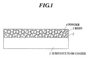
- FIG. 1 is a schematic cross-sectional view showing a formation process of a mixed layer according to the first embodiment of the present invention.
- FIGS. 2 and 3 are schematic cross-sectional views each showing a formation process of a coating according to the first embodiment of the present invention.
- a mixed layer 2 including a powder and resin is formed on a surface of a substance 1 to be coated.
- the substance 1 is not particularly limited but intended to metal, alloy or ceramic, which constitutes machinery parts, structural parts or industrial tools.
- a material of resin 3 that constitutes the mixed layer 2 is preferred to be selected from thermohardening resin that is cured at normal temperature, when heated, or the like, photo-curable resin such as an instantaneously curable resin, visible light curing resin, ultraviolet curable resin, or the like.
- the material affects workability or compatibility with a powder constituting the mixed layer, so the material is preferred to be selected as needed basis.
- a material of a powder 4 that constitutes the mixed layer 2 may be selected from resin, metal, intermetallic compound, metallic oxide, metallic carbide, ceramics, glass, cemented carbide, diamond, carbon, carbon nanotube, fullerene, cubic boron nitride, or the like.
- the material of the powder 4 is preferred to be selected corresponding to compatibility with the substance 1 to be coated or characteristic needed to the coating.
- the mixed layer 2 As a method for forming the mixed layer 2 on the surface of the substance 1, first applying a mixed material made by blending the powder 4 into the resin 3 on the surface of the substance 1. A spray used in coating or the like is preferred to be used in applying the mixed material.
- the mixed layer 2 may be formed on the surface of the substance 1 not by the applying method but by moving a sheet-like mixed layer so as to be placed on the surface of the substance 1.
- the mixed layer 2 is formed by the applying method, so the mixed layer 2 can be easily formed on any area of a surface of an arbitrary shape.
- Hardening the resin 3 before a laser radiation is preferred because retentivity of the resin 3 for trapping the powder 4 is heightened by hardening the resin 3.
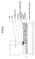
- FIGS. 2 and 3 cover an area of the surface of the mixed layer 2 with a transparent liquid 5, the area being at least an area to which plasma is to be irradiated. Then, radiate and focus a pulsed laser 7 through a lens 6 to the surface of the mixed layer 2 to generate plasma 8. Submerging the substance 1 to which the mixed layer 2 is annexed into the transparent liquid 5, as shown in FIG. 2 , or forming a transparent liquid film 10 on the mixed layer 2, as shown in FIG. 3 , may be available methods.
- the transparent liquid film 10 is formed in the form of flowing such as flowing water. In the case that the liquid is thick or semisolid, the film 10 is formed in the form of staying on the surface of the mixed layer 2.
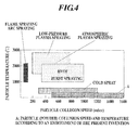
- FIG. 4 shows a comparison result of a particle collision speed, and particle temperature between principal thermal spray techniques and those of the present invention.
- the particle temperature is preferably set to be within the range from about 20 degrees C, which corresponds to a room temperature, to about 300 degrees C.
- the preferred particle collision speed in the present embodiment is 500 m/sec or more, and more preferably, about 500 to 1600 m/sec.
- the powder 4 is adhesively-bonded to the surface of the substance 1 with the surface being roughening processed by being plastic deformed to be finely caved, as shown in FIGS. 2 and 3 . Moreover, at almost the same time, the powder 4 runs into the bonded powder 4 at high velocities and laminated thereon to form a coating 11. Then, move an irradiation spot of the pulsed laser 7 to form the coating 11 in a needed area.
- Thickness of the coating 11 corresponds to the amount of the powder 4 included in the mixed layer 2 to be held on the surface of the substance 1 per unit area. Therefore, the thickness of the coating 11 formed by the plasma 8 can be controlled by selecting blend ratio of the powder 4 and thickness of the mixed layer 2.
- the coating 11 can be formed with its thickness being within the range of about 5 to 50 ⁇ m, though the thickness depends on material or particle diameter of the powder 4.
- the inventors of the present invention applied aluminum as the substance 1, epoxy resin as the resin 3 and ceramics powder as the powder 4.
- the irradiance condition of the pulsed laser is that the pulse energy is from 10 to 80 mJ and the laser is narrowed down to 0.4 to 1 mm by the lens 6. This led to the formation of a ceramics coating having thickness of 5 to 10 ⁇ m on the surface of the aluminum member without implanting the powder 4 into the substance 1, thereby having improved an abrasion resistance of the aluminum member.
- a coating having various functions or characteristics such as abrasion resistance or corrosion resistance can be formed on the surface of the substance 1 corresponding to a characteristics of the material of the powder 4.
- the coating 11 has high adhesion force to the surface of the substance 1. Moreover, the powder 4 becomes compression solidified by a high pressure of the shock wave, therefore, the coating 11 being highly condensed and having little pores therein can be formed.
- the coating 11 has a little residual stress because the temperature at a time of working and the heat generation thereof are lower than those of in the thermal spray. Moreover, there are no reductions in characteristics of the substance 1 caused by heat load. Consequently, it is possible to form a coating 11 having less decrease in fatigue characteristics thereof even if being compared with the thermal spray.
- FIGS. 5 and 6 are schematic cross-sectional views each showing a formation process of a coating according to the second embodiment of the present invention.
- the method of the present embodiment differs from the first embodiment in that the powder 4 includes two kinds of powders 4a and 4b. The other points are the same as that of the first embodiment.
- the mixed layer 2 includes two kinds of powders 4a and 4b.
- FIG. 5 or FIG. 6 irradiate the pulsed laser 7 in the same manner as the first embodiment with the mixed two kinds of powders 4a and 4b being included in the mixed layer 2.
- the plasma 8 arises because of the radiation of the pulsed laser 7.
- a shock wave of the plasma 8 runs the powders 4a and 4b into the surface of the substance 1 at high velocities to form a coating 12.
- the coating 12 including two kinds of materials material of the powder 4a and material of the powder 4b
- the coating 12 having multiple functions or characteristics can be formed.
- three or more kinds of powders may be mixed in the resin 3.
- FIGS. 7 and 8 are schematic cross-sectional views each showing a formation process of a coating according to the third embodiment of the present invention.
- the method of the present embodiment differs from the second embodiment in that the mixed layer being two-layered. The other points are the same as that of the second embodiment.
- the powders 4a and 4b are different kinds of materials.
- the resin 3 to be mixed with the powder 4a may be different from the resin 3 to be mixed with the powder 4b, or may be the same as the resin 3 to be mixed with the powder 4b.
- the powder 4b is arranged in a lower layer of the two-layered mixed layer 2 and the powder 4a is arranged in an upper layer of the two-layered mixed layer 2.
- FIGS. 7 and 8 irradiate the pulsed laser 7 in the same manner as the first embodiment with the mixed two kinds of powders 4a and 4b separately being arranged in the upper and the lower layers in the two-layered mixed layer 2.
- the plasma 8 arises because of the radiation of the pulsed laser 7.
- a shock wave of the plasma 8 runs the powders 4a and 4b into the surface of the substance 1 at high velocities, and the powder 4a runs into the powder 4b to be pressed to form a coating 13.
- the process is carried out by a big pulse energy that can implant the powder 4b into the substance 1, the powders 4a and 4b becomes mixed. Therefore, it is preferred that the process is accomplished at pulse energy lower than a pulse energy disclosed in the patent document 4. For example, set the pulse energy from 10 to 80 mJ and narrow down the laser to 0.4 to 1 mm by the lens 6. This can lead to the formation of the two-layered coating 13, in which material of powder 4b is arranged in relatively lower layer and material of powder 4a is arranged in relatively upper layer, as shown in FIGS. 7 and 8 .
- the present embodiment for example, by applying aluminum as the substance 1, carbon as the powder 4a and ceramics as the powder 4b, ceramics intermediate between aluminum and carbon. Consequently, carbon coating, which is incompatible with aluminum, can be formed on an outer surface of an aluminum member. It is possible to form a coating of material, which is not suitable to be directly formed on the substance 1 for a chemical reason or a mechanical reason such as thermal stress. It is also possible to obtain multiple functions or characteristics of a two-layered coating composed of two different materials. Needless to say, the mixed layer 2 may have a three-layered structure or more.
- the two-layered coating composed of different materials can be formed by repeating the above-mentioned steps of the first embodiment twice.
- the present embodiment has an advantage from the viewpoint of manufacturing step because the two-layered coating can be formed by one step of laser radiation.
- interlayer mixing degree can be controlled and so-called gradient function can be realized.
- a coating 14 in which an upper layer and a lower layer respectively includes mixed materials of powders 4a and 4b with the blend ratio thereof varies between the upper layer and the lower layer, can be formed.
- the number of layers, a blend ratio in each of the layers, and a kind of powder or the number of kinds of the powders to be mixed in each of the layers are arbitrary.
- a layer including one kind of powder may arbitrary be added on top of or under a layer including two or more kinds of mixed powders.
- FIGS. 9 and 10 show an example of forming the coating 14 in which a layer including materials of powders 4a and 4b in the proportion of two parts to one is arranged on top of a layer including materials of powders 4a and 4b in the proportion of one part to two.
- Method of formation will be described with taking the FIGS. 9 and 10 as an example.
- a material, in which powders 4a and 4b in the proportion of two parts to one are mixed in the resin 3 is applied to form two-layered mixed layer 2. Cure the applied resin 3.
- the pulsed laser 7 is irradiated under the condition that the mixed layer 2 including two or more layers, each of which includes two or more kinds of powders at different blend ratio at each of the layers, are formed.
- two-layered mixed layer 2 including two layers each of which having different blend ratio of the different powders in each layer
- a coating having different blend ratio of materials in each layer can be formed.
- the two-layered coating 14 in which the layer having high blend ratio of powder 4b is arranged relatively low and the layer having high blend ratio of powder 4a is arranged relatively high, can be formed. It may be possible to form the coating to be three or more layered and provide continuous ratio changing by slightly varying the blend ratio. It may also be possible to provide discontinuous ratio changing by greatly varying the blend ratio between adjacent layers.
- the coating characteristics vary continuously or discontinuously in a stepwise fashion or the like as departing from the surface of the substance 1, and that constituent material or characteristic of the coating has a depth variation such as, for example, change characteristics that increase gradually or decrease gradually at a slant corresponding to the depth.
Abstract
Description
- The present invention relates to a coating method using a plasma shock wave and a method for manufacturing a coated substance.
- Heretofore, a laser peening method is used as a method using a plasma shock wave for reforming surfaces of such as machinery parts by applying residual stress into the surfaces.
- Processing that uses the laser peening method is generally taken place by irradiating convergent laser beam to a surface to be worked, trapping produced plasma into a liquid medium such as water, oil, or the like, the liquid medium being formed on the surface to be worked, and applying a shock wave pressure generated thereby to the surface to be worked. Liquid such as water, oil, or the like for trapping plasma therein, needs to be formed on the surface to be worked so that the shock wave pressure generated by the plasma may be effectively applied to the surface to be worked.
- Patent documents
JP-A-2000-246468 JP-A-2006-122969 JP-A-2007-169753 JP-A-2006-122969 - Patent document
JP-A-2002-346847 FIGs. 10 and 11 in the document). - Moreover, the document discloses a peening method using a water-jet in combination with a laser (see the CLAIMS and
FIG. 1 and so on). - Moreover, patent document
JP-A-2007-169753 - According to the laser peening method, the powder is struck into the surface to be worked by irradiating the laser to a base sheet laid down on the surface to be worked, the base sheet preliminarily been made to carry the powder on one side thereof (see paragraphs 0040-0044 and
FIG. 1 in the documentJP-A-2007-1-69753 FIG. 2 in the documentJP-A-2007-169753 - However, the technique disclosed in the patent document
JP-A-2007-169753 - As a coating technology, a thermal spraying including a flame spraying, a burst spraying, an electrical spraying such as an arc spraying and a plasma spraying or the like, a high-speed flame spraying (HVOF) or a cold spraying is used.
- It is, therefore, a main object of the present invention to provide a coating method for forming a coating by using the plasma shock wave and a method for manufacturing a coated substance. Moreover, the present invention aims to provide a coating method in which thickness of the coating can be controlled by using a shock wave generated by the plasma. Moreover, the present invention aims to provide a coating method, which forms coating superior in adhesion strength or the like by taking advantage of a laser peening method in which particle collision speed is faster than that of in the thermal spray.
- According to a first aspect of the present invention, there is provided a coating method using a plasma shock wave, the method including the steps of: irradiating a pulse laser to a first surface of a mixed layer including a powder and resin to generate a plasma, the mixed layer being formed on a second surface of a substance to be coated; running the powder into the second surface by using a shock wave arisen from the plasma; and forming a coat of the powder on the second surface.
- Preferably, irradiating the pulse laser is prosecuted under a condition that the mixed layer is formed on the second surface by hardening the resin after applying an admixture ingredient including the powder and the resin to the second surface.
- Preferably, irradiating the pulse laser is prosecuted under a condition that the mixed layer includes two or more different kinds of the powder.
- Preferably, irradiating the pulse laser is prosecuted under a condition that the mixed layer is composed of two or more layers, each of the layers including the powder varying from one layer to another.
- Preferably, irradiating the pulse laser is prosecuted under a condition that the mixed layer is composed of two or more layers, each of the layers including two or more different kinds of the powder at different blend ratio.
- According to a second aspect of the present invention, there is provided a method for manufacturing a coated substance using a plasma shock wave, the method including the steps of: irradiating a pulse laser to a first surface of a mixed layer obtained by mixing powders and resin to generate a plasma, the mixed layer being formed on a second surface of a substance to be coated; striking the powders on the second surface by using a shock wave of the plasma; and forming a coat of the powders on the second surface.
- According to the first and second aspects of the present invention, the resin included in the mixed layer has a role to carry the powder. The amount of the powder to be carried on the surface to be worked can be obtained sufficiently per unit area by selecting a blend ratio of the powder and a thickness of the mixed layer. Therefore, the coating composed of the powder can be formed on the second surface by running sufficient amount of the powder into the second surface by the shock wave arisen from the plasma.
- The above and other objects, advantages and features of the present invention will become more fully understood from the detailed description given hereinbelow and the appended drawings which are given by way of illustration only, and thus are not intended as a definition of the limits of the present invention, and wherein:
-
FIG. 1 is a schematic cross-sectional view showing a formation process of a mixed layer according to the first embodiment of the present invention; -
FIG. 2 is a schematic cross-sectional view showing a formation process of a coating according to the first embodiment of the present invention; -
FIG. 3 is a schematic cross-sectional view showing a formation process of a coating according to the first embodiment of the present invention; -
FIG. 4 is a graph showing a comparison result of a particle collision speed and particle temperature between principal thermal spray techniques and those of the present invention; -
FIG. 5 is a schematic cross-sectional view showing a formation process of a coating according to a second embodiment of the present invention; -
FIG. 6 is a schematic cross-sectional view showing a formation process of a coating according to the second embodiment of the present invention; -
FIG. 7 is a schematic cross-sectional view showing a formation process of a coating according to a third embodiment of the present invention; -
FIG. 8 is a schematic cross-sectional view showing a formation process of a coating according to the third embodiment of the present invention; -
FIG. 9 is a schematic cross-sectional view showing a formation process of a coating according to a fourth embodiment of the present invention; and -
FIG. 10 is a schematic cross-sectional view showing a formation process of a coating according to the fourth embodiment of the present invention. - The best mode for carrying out the present invention will be described hereinbelow with reference to the drawings. The followings are embodiments of the present invention, which are not intended to limit the scope of the present invention.
- First of all, a first embodiment of the present invention will be described with reference to
FIGS. 1-4 .FIG. 1 is a schematic cross-sectional view showing a formation process of a mixed layer according to the first embodiment of the present invention.FIGS. 2 and3 are schematic cross-sectional views each showing a formation process of a coating according to the first embodiment of the present invention. - At first, as shown in
FIG. 1 , a mixedlayer 2 including a powder and resin is formed on a surface of asubstance 1 to be coated. - The
substance 1 is not particularly limited but intended to metal, alloy or ceramic, which constitutes machinery parts, structural parts or industrial tools. - A material of
resin 3 that constitutes the mixedlayer 2 is preferred to be selected from thermohardening resin that is cured at normal temperature, when heated, or the like, photo-curable resin such as an instantaneously curable resin, visible light curing resin, ultraviolet curable resin, or the like. However, the material affects workability or compatibility with a powder constituting the mixed layer, so the material is preferred to be selected as needed basis. - A material of a
powder 4 that constitutes the mixedlayer 2 may be selected from resin, metal, intermetallic compound, metallic oxide, metallic carbide, ceramics, glass, cemented carbide, diamond, carbon, carbon nanotube, fullerene, cubic boron nitride, or the like. The material of thepowder 4 is preferred to be selected corresponding to compatibility with thesubstance 1 to be coated or characteristic needed to the coating. - As a method for forming the
mixed layer 2 on the surface of thesubstance 1, first applying a mixed material made by blending thepowder 4 into theresin 3 on the surface of thesubstance 1. A spray used in coating or the like is preferred to be used in applying the mixed material. Themixed layer 2 may be formed on the surface of thesubstance 1 not by the applying method but by moving a sheet-like mixed layer so as to be placed on the surface of thesubstance 1. In the present embodiment, themixed layer 2 is formed by the applying method, so the mixedlayer 2 can be easily formed on any area of a surface of an arbitrary shape. - Then, harden the
resin 3 in themixed layer 2 applied on the surface of thesubstance 1. Hardening theresin 3 before a laser radiation is preferred because retentivity of theresin 3 for trapping thepowder 4 is heightened by hardening theresin 3. - Next, as shown in, for example,
FIGS. 2 and3 , cover an area of the surface of themixed layer 2 with atransparent liquid 5, the area being at least an area to which plasma is to be irradiated. Then, radiate and focus apulsed laser 7 through alens 6 to the surface of the mixedlayer 2 to generateplasma 8. Submerging thesubstance 1 to which themixed layer 2 is annexed into thetransparent liquid 5, as shown inFIG. 2 , or forming a transparentliquid film 10 on themixed layer 2, as shown inFIG. 3 , may be available methods. - Here, water, oil or the like can be applied to the transparent liquid. The transparent
liquid film 10 is formed in the form of flowing such as flowing water. In the case that the liquid is thick or semisolid, thefilm 10 is formed in the form of staying on the surface of the mixedlayer 2. - As described above, a shock wave is arisen by the
plasma 8 generated by irradiating thepulsed laser 7. Thepowder 4 included in themixed layer 2 is run into the surface of thesubstance 1 at high velocities by the shock wave. The collision speed varies corresponding to materials of thepowder 4 andresin 3, mix ratio of thepowder 4 to theresin 3 and irradiance condition of the laser. However, the collision speed is usually faster compared with the thermal spray as shown inFIG. 4. FIG. 4 shows a comparison result of a particle collision speed, and particle temperature between principal thermal spray techniques and those of the present invention. In the present embodiment, the particle temperature is preferably set to be within the range from about 20 degrees C, which corresponds to a room temperature, to about 300 degrees C. The preferred particle collision speed in the present embodiment is 500 m/sec or more, and more preferably, about 500 to 1600 m/sec. - By the shock wave of
plasma 8, thepowder 4 is adhesively-bonded to the surface of thesubstance 1 with the surface being roughening processed by being plastic deformed to be finely caved, as shown inFIGS. 2 and3 . Moreover, at almost the same time, thepowder 4 runs into the bondedpowder 4 at high velocities and laminated thereon to form acoating 11. Then, move an irradiation spot of thepulsed laser 7 to form thecoating 11 in a needed area. - Thickness of the
coating 11 corresponds to the amount of thepowder 4 included in themixed layer 2 to be held on the surface of thesubstance 1 per unit area. Therefore, the thickness of thecoating 11 formed by theplasma 8 can be controlled by selecting blend ratio of thepowder 4 and thickness of themixed layer 2. Thecoating 11 can be formed with its thickness being within the range of about 5 to 50 µm, though the thickness depends on material or particle diameter of thepowder 4. - The inventors of the present invention applied aluminum as the
substance 1, epoxy resin as theresin 3 and ceramics powder as thepowder 4. The irradiance condition of the pulsed laser is that the pulse energy is from 10 to 80 mJ and the laser is narrowed down to 0.4 to 1 mm by thelens 6. This led to the formation of a ceramics coating having thickness of 5 to 10 µm on the surface of the aluminum member without implanting thepowder 4 into thesubstance 1, thereby having improved an abrasion resistance of the aluminum member. - As described above, according to the coating method of the present invention, a coating having various functions or characteristics such as abrasion resistance or corrosion resistance can be formed on the surface of the
substance 1 corresponding to a characteristics of the material of thepowder 4. - Moreover, as shown in
FIG. 4 , it is possible to run thepowder 4 into thesubstance 1 at a particle collision speed faster than that of the thermal spray. Therefore, thecoating 11 has high adhesion force to the surface of thesubstance 1. Moreover, thepowder 4 becomes compression solidified by a high pressure of the shock wave, therefore, thecoating 11 being highly condensed and having little pores therein can be formed. - Moreover, as shown in
FIG. 4 , thecoating 11 has a little residual stress because the temperature at a time of working and the heat generation thereof are lower than those of in the thermal spray. Moreover, there are no reductions in characteristics of thesubstance 1 caused by heat load. Consequently, it is possible to form acoating 11 having less decrease in fatigue characteristics thereof even if being compared with the thermal spray. Second Embodiment - Next, a second embodiment of the present invention will be described with reference to
FIGS. 5 and6 .FIGS. 5 and6 are schematic cross-sectional views each showing a formation process of a coating according to the second embodiment of the present invention. The method of the present embodiment differs from the first embodiment in that thepowder 4 includes two kinds ofpowders - Apply a material composed by mixing the
resin 3 and two kinds ofpowders substance 1, and then cure theresin 3. Themixed layer 2 includes two kinds ofpowders - Next, as shown in
FIG. 5 orFIG. 6 , irradiate thepulsed laser 7 in the same manner as the first embodiment with the mixed two kinds ofpowders mixed layer 2. Theplasma 8 arises because of the radiation of thepulsed laser 7. Then, a shock wave of theplasma 8 runs thepowders substance 1 at high velocities to form acoating 12. Then, move an irradiation spot of thepulsed laser 7 to form thecoating 12 in a needed area. - As shown in
FIGS. 5 and6 , thecoating 12 including two kinds of materials (material of thepowder 4a and material of thepowder 4b) is formed. That is, thecoating 12 having multiple functions or characteristics can be formed. Off course, three or more kinds of powders may be mixed in theresin 3. Third Embodiment - Next, a third embodiment of the present invention will be described with reference to
FIGS. 7 and8 .FIGS. 7 and8 are schematic cross-sectional views each showing a formation process of a coating according to the third embodiment of the present invention. The method of the present embodiment differs from the second embodiment in that the mixed layer being two-layered. The other points are the same as that of the second embodiment. - Apply a material composed by mixing the
resin 3 andpowder 4b on the surface of thesubstance 1, and cure the appliedresin 3. Then, on top thereof, apply a material composed by mixing theresin 3 andpowder 4a to form two-layeredmixed layer 2, and cure the appliedresin 3. - The
powders powders resin 3 to be mixed with thepowder 4a may be different from theresin 3 to be mixed with thepowder 4b, or may be the same as theresin 3 to be mixed with thepowder 4b. - As shown in
FIGS. 7 and8 , thepowder 4b is arranged in a lower layer of the two-layeredmixed layer 2 and thepowder 4a is arranged in an upper layer of the two-layeredmixed layer 2. - Next, as shown in
FIGS. 7 and8 , irradiate thepulsed laser 7 in the same manner as the first embodiment with the mixed two kinds ofpowders mixed layer 2. Theplasma 8 arises because of the radiation of thepulsed laser 7. Then, a shock wave of theplasma 8 runs thepowders substance 1 at high velocities, and thepowder 4a runs into thepowder 4b to be pressed to form acoating 13. Then, move an irradiation spot of thepulsed laser 7 to form thecoating 13 in a needed area. - At this time, if the process is carried out by a big pulse energy that can implant the
powder 4b into thesubstance 1, thepowders patent document 4. For example, set the pulse energy from 10 to 80 mJ and narrow down the laser to 0.4 to 1 mm by thelens 6. This can lead to the formation of the two-layeredcoating 13, in which material ofpowder 4b is arranged in relatively lower layer and material ofpowder 4a is arranged in relatively upper layer, as shown inFIGS. 7 and8 . - According to the present embodiment, for example, by applying aluminum as the
substance 1, carbon as thepowder 4a and ceramics as thepowder 4b, ceramics intermediate between aluminum and carbon. Consequently, carbon coating, which is incompatible with aluminum, can be formed on an outer surface of an aluminum member. It is possible to form a coating of material, which is not suitable to be directly formed on thesubstance 1 for a chemical reason or a mechanical reason such as thermal stress. It is also possible to obtain multiple functions or characteristics of a two-layered coating composed of two different materials. Needless to say, themixed layer 2 may have a three-layered structure or more. - The two-layered coating composed of different materials can be formed by repeating the above-mentioned steps of the first embodiment twice. In contrast, the present embodiment has an advantage from the viewpoint of manufacturing step because the two-layered coating can be formed by one step of laser radiation. Moreover, by properly controlling conditions of laser to radiate such as a pulse energy or radiation diameter, interlayer mixing degree can be controlled and so-called gradient function can be realized.
- As an application of the above-mentioned second and third embodiments, as shown in
FIGS. 9 and10 , acoating 14, in which an upper layer and a lower layer respectively includes mixed materials ofpowders -
FIGS. 9 and10 show an example of forming thecoating 14 in which a layer including materials ofpowders powders FIGS. 9 and10 as an example. First, apply a material, in which powders 4a and 4b in the proportion of one part to two are mixed in theresin 3, to the surface of thesubstance 1 and cure the appliedresin 3. Then, to the top thereon, a material, in which powders 4a and 4b in the proportion of two parts to one are mixed in theresin 3 is applied to form two-layeredmixed layer 2. Cure the appliedresin 3. Then, irradiate thepulsed laser 7 in the same manner as aforementioned. As described above, the pulsed laser is irradiated under the condition that themixed layer 2 including two or more layers, each of which includes two or more kinds of powders at different blend ratio at each of the layers, are formed. - By forming two-layered
mixed layer 2 including two layers each of which having different blend ratio of the different powders in each layer, a coating having different blend ratio of materials in each layer can be formed. In the example shown inFIGS. 9 and10 , the two-layeredcoating 14, in which the layer having high blend ratio ofpowder 4b is arranged relatively low and the layer having high blend ratio ofpowder 4a is arranged relatively high, can be formed. It may be possible to form the coating to be three or more layered and provide continuous ratio changing by slightly varying the blend ratio. It may also be possible to provide discontinuous ratio changing by greatly varying the blend ratio between adjacent layers. - It may be possible that the coating characteristics vary continuously or discontinuously in a stepwise fashion or the like as departing from the surface of the
substance 1, and that constituent material or characteristic of the coating has a depth variation such as, for example, change characteristics that increase gradually or decrease gradually at a slant corresponding to the depth.
Claims (10)
- A coating method using a plasma shock wave, the method comprising the steps of:irradiating a pulse laser to a first surface of a mixed layer obtained by mixing powders and resin to generate a plasma, the mixed layer being formed on a second surface of a substance to be coated;striking the powders on the second surface by using a shock wave of the plasma; andforming a coat of the powders on the second surface.
- The coating method according to claim 1, further comprising a step of forming the mixed layer on the second surface by hardening the resin after applying an admixture ingredient including the powders and the resin to the second surface.
- The coating method according to claim 1 or 2, wherein
irradiating the pulse laser is prosecuted under a condition that the mixed layer includes two or more different kinds of the powders. - The coating method according to claim 1 or 2, wherein
irradiating the pulse laser is prosecuted under a condition that the mixed layer is composed of two or more layers, each of the layers including the powders of different kind from one layer to another. - The coating method according to claim 3, wherein
irradiating the pulse laser is prosecuted under a condition that the mixed layer is composed of two or more layers, each of the layers including two or more different kinds of the powders at different blend ratio. - A method for manufacturing a coated substance using a plasma shock wave, the method comprising the steps of:irradiating a pulse laser to a first surface of a mixed layer obtained by mixing powders and resin to generate a plasma, the mixed layer being formed on a second surface of a substance to be coated;striking the powders on the second surface by using a shock wave of the plasma; andforming a coat of the powders on the second surface.
- The method according to claim 6, further comprising a step of forming the mixed layer on the second surface by hardening the resin after applying an admixture ingredient including the powders and the resin to the second surface.
- The method according to claim 6 or 7, wherein
irradiating the pulse laser is prosecuted under a condition that the mixed layer includes two or more different kinds of the powders. - The method according to claim 6 or 7, wherein
irradiating the pulse laser is prosecuted under a condition that the mixed layer is composed of two or more layers, each of the layers including the powders of different kind from one layer to another. - The method according to claim 8, wherein
irradiating the pulse laser is prosecuted under a condition that the mixed layer is composed of two or more layers, each of the layers including two or more different kinds of the powders at different blend ratio.
Applications Claiming Priority (1)
| Application Number | Priority Date | Filing Date | Title |
|---|---|---|---|
| JP2008231025A JP5230312B2 (en) | 2008-09-09 | 2008-09-09 | Coating method using plasma shock wave |
Publications (3)
| Publication Number | Publication Date |
|---|---|
| EP2161353A2 true EP2161353A2 (en) | 2010-03-10 |
| EP2161353A3 EP2161353A3 (en) | 2010-12-22 |
| EP2161353B1 EP2161353B1 (en) | 2019-07-24 |
Family
ID=41265560
Family Applications (1)
| Application Number | Title | Priority Date | Filing Date |
|---|---|---|---|
| EP09169799.5A Not-in-force EP2161353B1 (en) | 2008-09-09 | 2009-09-09 | Coating method using plasma shock wave and method for manufacturing coated substance |
Country Status (3)
| Country | Link |
|---|---|
| US (1) | US8906469B2 (en) |
| EP (1) | EP2161353B1 (en) |
| JP (1) | JP5230312B2 (en) |
Cited By (1)
| Publication number | Priority date | Publication date | Assignee | Title |
|---|---|---|---|---|
| WO2014128196A3 (en) * | 2013-02-21 | 2014-10-16 | Hsp Schwahlen Gmbh | Bearing component of a rolling or sliding bearing, and method for producing same |
Families Citing this family (7)
| Publication number | Priority date | Publication date | Assignee | Title |
|---|---|---|---|---|
| US9192056B2 (en) * | 2011-09-12 | 2015-11-17 | Lawrence Livermore National Security, Llc | Methods and system for controlled laser-driven explosive bonding |
| WO2015064434A1 (en) * | 2013-10-30 | 2015-05-07 | アイシン精機株式会社 | Piston and process for producing piston |
| JP6328410B2 (en) * | 2013-11-29 | 2018-05-23 | アイシン精機株式会社 | Manufacturing method of aluminum alloy member |
| JP6195780B2 (en) * | 2013-10-30 | 2017-09-13 | アイシン精機株式会社 | Piston and manufacturing method of piston |
| CN103614541B (en) * | 2013-10-31 | 2015-08-19 | 中国科学院宁波材料技术与工程研究所 | For laser impact intensified device and the laser impact intensified treatment process of workpiece surface |
| US11167375B2 (en) | 2018-08-10 | 2021-11-09 | The Research Foundation For The State University Of New York | Additive manufacturing processes and additively manufactured products |
| CN111957542A (en) * | 2020-08-11 | 2020-11-20 | 江苏万源新材料股份有限公司 | Coating aluminum foil with moisturizing function and preparation process thereof |
Family Cites Families (23)
| Publication number | Priority date | Publication date | Assignee | Title |
|---|---|---|---|---|
| JPS531642A (en) * | 1976-06-28 | 1978-01-09 | Inoue Japax Res | Surface coating and shaping method |
| JPS6254588A (en) * | 1985-08-30 | 1987-03-10 | Toyota Motor Corp | Formation of composite aluminum alloy layer dispersed with ceramic particles |
| CA2072070A1 (en) * | 1990-01-11 | 1991-07-12 | Harold M. Epstein | Material properties |
| JPH05125557A (en) * | 1991-10-30 | 1993-05-21 | Kobe Steel Ltd | Coating method using laser beam |
| RU2086698C1 (en) * | 1994-08-03 | 1997-08-10 | Вудфорд Трейдинг Лимитед | Method of surface treatment of metal carrier |
| US5614339A (en) * | 1995-08-09 | 1997-03-25 | Lumedics, Ltd. | Object recycling by laser of coating material |
| US5741559A (en) * | 1995-10-23 | 1998-04-21 | Lsp Technologies, Inc. | Laser peening process and apparatus |
| US5985056A (en) * | 1996-01-15 | 1999-11-16 | The University Of Tennessee Research Corporation | Method for laser induced improvement of surfaces |
| IL124985A (en) * | 1996-01-15 | 2001-10-31 | Univ Tennessee Res Corp | Laser induced improvement of surfaces |
| US6350326B1 (en) * | 1996-01-15 | 2002-02-26 | The University Of Tennessee Research Corporation | Method for practicing a feedback controlled laser induced surface modification |
| US6049058A (en) * | 1998-12-15 | 2000-04-11 | Lsp Technologies, Inc. | Laser peening process and apparatus with uniform pressure pulse confinement |
| US6197133B1 (en) * | 1999-02-16 | 2001-03-06 | General Electric Company | Short-pulse high-peak laser shock peening |
| JP2002346847A (en) | 2001-05-24 | 2002-12-04 | Babcock Hitachi Kk | Peening method and apparatus by combined use of water jet and laser |
| US6623376B2 (en) * | 2001-06-18 | 2003-09-23 | Acushnet Company | Peen conditioning of titanium metal wood golf club heads |
| US6583384B2 (en) * | 2001-07-23 | 2003-06-24 | Lsp Technologies, Inc. | UV curable overlays for laser shock processing |
| GB2398034B (en) * | 2003-02-04 | 2005-08-10 | Rolls Royce Plc | Laser shock peening |
| US7268317B2 (en) * | 2003-09-02 | 2007-09-11 | Lsp Technologies, Inc. | Laser peening process and apparatus using a liquid erosion-resistant opaque overlay coating |
| JP2006122969A (en) | 2004-10-29 | 2006-05-18 | Muneharu Kutsuna | Welded joint of metallic material and metallic clad material, and laser peening of casting material |
| JP2006320907A (en) * | 2005-05-17 | 2006-11-30 | Muneharu Kutsuna | Micro-laser peening treatment using powder and film, and micro-laser peening-treated component |
| JP2007169754A (en) * | 2005-12-26 | 2007-07-05 | Muneharu Kutsuna | Surface treatment method, laser absorption powder layer sheet and powder spray for laser peening |
| JP4058448B2 (en) | 2005-12-26 | 2008-03-12 | 宗春 沓名 | Laser peening treatment method and laser absorbing powder layer sheet |
| US20090314824A1 (en) * | 2007-01-26 | 2009-12-24 | Kazuo Sawaguchi | Metal surface treatment method |
| US7861573B1 (en) * | 2007-11-28 | 2011-01-04 | Lsp Technologies, Inc. | Laser shock induced spallation |
-
2008
- 2008-09-09 JP JP2008231025A patent/JP5230312B2/en active Active
-
2009
- 2009-09-08 US US12/555,433 patent/US8906469B2/en not_active Expired - Fee Related
- 2009-09-09 EP EP09169799.5A patent/EP2161353B1/en not_active Not-in-force
Non-Patent Citations (1)
| Title |
|---|
| None |
Cited By (1)
| Publication number | Priority date | Publication date | Assignee | Title |
|---|---|---|---|---|
| WO2014128196A3 (en) * | 2013-02-21 | 2014-10-16 | Hsp Schwahlen Gmbh | Bearing component of a rolling or sliding bearing, and method for producing same |
Also Published As
| Publication number | Publication date |
|---|---|
| EP2161353A3 (en) | 2010-12-22 |
| US8906469B2 (en) | 2014-12-09 |
| US20100062179A1 (en) | 2010-03-11 |
| EP2161353B1 (en) | 2019-07-24 |
| JP5230312B2 (en) | 2013-07-10 |
| JP2010065253A (en) | 2010-03-25 |
Similar Documents
| Publication | Publication Date | Title |
|---|---|---|
| EP2161353B1 (en) | Coating method using plasma shock wave and method for manufacturing coated substance | |
| US10166751B2 (en) | Method for enhanced additive manufacturing | |
| Champagne et al. | Interface material mixing formed by the deposition of copper on aluminum by means of the cold spray process | |
| US7066235B2 (en) | Method for manufacturing clad components | |
| Kaplan et al. | Process analysis of laser beam cladding | |
| CN1817639A (en) | Composite reactive multilayer foil | |
| EP1960154B1 (en) | Laser peening method, product and apparatus with such product, using ablation layers to prevent pitting during laser peening | |
| CN101589174A (en) | Metal surface treatment method | |
| JP2007169753A (en) | Laser peening treatment method and laser absorption powder layer sheet | |
| Kromer et al. | Cold gas-sprayed deposition of metallic coatings onto ceramic substrates using laser surface texturing pre-treatment | |
| US20100155374A1 (en) | process for energy beam solid-state metallurgical bonding of wires having two or more flat surfaces | |
| JP2011518956A (en) | Method for coating fiber composite member for aircraft and spacecraft, and fiber composite member produced by the method | |
| US20220080522A1 (en) | Hybrid solid-state additive and subtractive manufacturing processes, materials used and parts fabricated with the hybrid processes | |
| RU2373036C1 (en) | Method of fabrication of wear resistant coating | |
| US20090092823A1 (en) | Braze-metal coated articles and process for making same | |
| Brückner et al. | Surface Functionalization by High‐precision Laser Cladding: Process equipment and manufacturing strategies for miniaturized and customized components | |
| US11890788B2 (en) | Methods and process for producing polymer-metal hybrid components bonded by C—O-M bonds | |
| US20060165884A1 (en) | Increasing fiber volume and/or uniformity in an ultrasonically consolidated fiber reinforced metal-matrix composite | |
| Mahamood et al. | Additive manufacturing of funtionally graded materials | |
| Astarita et al. | Laser cutting of aluminium sheets with a superficial cold spray titanium coating | |
| Luo et al. | Study on anti-wear property of 3D printed-tools in friction stir welding by numerical and physical experiments | |
| JP2004360904A (en) | Heat insulation material and formation method of heat insulation material | |
| WO2021173968A1 (en) | Methods to create structures with engineered internal features, pores, and/or connected channels utilizing cold spray particle deposition | |
| RU2655408C1 (en) | Method for application of wear-resistant coatings based on titanium carbide, nickel and molybdenum on die steels | |
| US20200009655A1 (en) | Processes and systems for double-pulse laser micro sintering |
Legal Events
| Date | Code | Title | Description |
|---|---|---|---|
| PUAI | Public reference made under article 153(3) epc to a published international application that has entered the european phase |
Free format text: ORIGINAL CODE: 0009012 |
|
| AK | Designated contracting states |
Kind code of ref document: A2 Designated state(s): AT BE BG CH CY CZ DE DK EE ES FI FR GB GR HR HU IE IS IT LI LT LU LV MC MK MT NL NO PL PT RO SE SI SK SM TR |
|
| PUAL | Search report despatched |
Free format text: ORIGINAL CODE: 0009013 |
|
| AK | Designated contracting states |
Kind code of ref document: A3 Designated state(s): AT BE BG CH CY CZ DE DK EE ES FI FR GB GR HR HU IE IS IT LI LT LU LV MC MK MT NL NO PL PT RO SE SI SK SM TR |
|
| RIC1 | Information provided on ipc code assigned before grant |
Ipc: C23C 24/04 20060101AFI20091113BHEP Ipc: B23K 26/18 20060101ALI20101117BHEP Ipc: C23C 26/00 20060101ALI20101117BHEP Ipc: C23C 24/08 20060101ALI20101117BHEP Ipc: C23C 4/18 20060101ALI20101117BHEP |
|
| 17P | Request for examination filed |
Effective date: 20110621 |
|
| RAP1 | Party data changed (applicant data changed or rights of an application transferred) |
Owner name: FUJI JUKOGYO KABUSHIKI KAISHA Owner name: TOSHIBA CORPORATION |
|
| STAA | Information on the status of an ep patent application or granted ep patent |
Free format text: STATUS: EXAMINATION IS IN PROGRESS |
|
| 17Q | First examination report despatched |
Effective date: 20170210 |
|
| RAP1 | Party data changed (applicant data changed or rights of an application transferred) |
Owner name: SUBARU CORPORATION Owner name: TOSHIBA CORPORATION |
|
| REG | Reference to a national code |
Ref country code: DE Ref legal event code: R079 Ref document number: 602009059198 Country of ref document: DE Free format text: PREVIOUS MAIN CLASS: C23C0024040000 Ipc: C23C0024100000 |
|
| RAP1 | Party data changed (applicant data changed or rights of an application transferred) |
Owner name: TOSHIBA ENERGY SYSTEMS & SOLUTIONS CORPORATION Owner name: SUBARU CORPORATION |
|
| GRAP | Despatch of communication of intention to grant a patent |
Free format text: ORIGINAL CODE: EPIDOSNIGR1 |
|
| STAA | Information on the status of an ep patent application or granted ep patent |
Free format text: STATUS: GRANT OF PATENT IS INTENDED |
|
| RIC1 | Information provided on ipc code assigned before grant |
Ipc: C23C 24/10 20060101AFI20180727BHEP Ipc: B23K 26/34 20060101ALI20180727BHEP Ipc: B23K 26/32 20060101ALI20180727BHEP Ipc: C23C 24/04 20060101ALI20180727BHEP Ipc: B23K 103/00 20060101ALI20180727BHEP Ipc: C23C 26/00 20060101ALI20180727BHEP Ipc: C23C 24/08 20060101ALI20180727BHEP Ipc: C23C 4/18 20060101ALI20180727BHEP |
|
| INTG | Intention to grant announced |
Effective date: 20180905 |
|
| GRAJ | Information related to disapproval of communication of intention to grant by the applicant or resumption of examination proceedings by the epo deleted |
Free format text: ORIGINAL CODE: EPIDOSDIGR1 |
|
| STAA | Information on the status of an ep patent application or granted ep patent |
Free format text: STATUS: EXAMINATION IS IN PROGRESS |
|
| GRAP | Despatch of communication of intention to grant a patent |
Free format text: ORIGINAL CODE: EPIDOSNIGR1 |
|
| STAA | Information on the status of an ep patent application or granted ep patent |
Free format text: STATUS: GRANT OF PATENT IS INTENDED |
|
| INTC | Intention to grant announced (deleted) | ||
| RIN1 | Information on inventor provided before grant (corrected) |
Inventor name: SANO, YUJI Inventor name: CHIDA, ITARU Inventor name: ADACHI, TAKAFUMI Inventor name: TAKEHISA, HIROYUKI |
|
| RIN1 | Information on inventor provided before grant (corrected) |
Inventor name: CHIDA, ITARU Inventor name: TAKEHISA, HIROYUKI Inventor name: ADACHI, TAKAFUMI Inventor name: SANO, YUJI |
|
| INTG | Intention to grant announced |
Effective date: 20190121 |
|
| GRAS | Grant fee paid |
Free format text: ORIGINAL CODE: EPIDOSNIGR3 |
|
| GRAJ | Information related to disapproval of communication of intention to grant by the applicant or resumption of examination proceedings by the epo deleted |
Free format text: ORIGINAL CODE: EPIDOSDIGR1 |
|
| GRAL | Information related to payment of fee for publishing/printing deleted |
Free format text: ORIGINAL CODE: EPIDOSDIGR3 |
|
| STAA | Information on the status of an ep patent application or granted ep patent |
Free format text: STATUS: EXAMINATION IS IN PROGRESS |
|
| GRAR | Information related to intention to grant a patent recorded |
Free format text: ORIGINAL CODE: EPIDOSNIGR71 |
|
| STAA | Information on the status of an ep patent application or granted ep patent |
Free format text: STATUS: GRANT OF PATENT IS INTENDED |
|
| GRAA | (expected) grant |
Free format text: ORIGINAL CODE: 0009210 |
|
| STAA | Information on the status of an ep patent application or granted ep patent |
Free format text: STATUS: THE PATENT HAS BEEN GRANTED |
|
| INTG | Intention to grant announced |
Effective date: 20190613 |
|
| AK | Designated contracting states |
Kind code of ref document: B1 Designated state(s): AT BE BG CH CY CZ DE DK EE ES FI FR GB GR HR HU IE IS IT LI LT LU LV MC MK MT NL NO PL PT RO SE SI SK SM TR |
|
| REG | Reference to a national code |
Ref country code: GB Ref legal event code: FG4D |
|
| REG | Reference to a national code |
Ref country code: CH Ref legal event code: EP |
|
| REG | Reference to a national code |
Ref country code: DE Ref legal event code: R096 Ref document number: 602009059198 Country of ref document: DE |
|
| REG | Reference to a national code |
Ref country code: AT Ref legal event code: REF Ref document number: 1158293 Country of ref document: AT Kind code of ref document: T Effective date: 20190815 |
|
| REG | Reference to a national code |
Ref country code: IE Ref legal event code: FG4D |
|
| REG | Reference to a national code |
Ref country code: NL Ref legal event code: MP Effective date: 20190724 |
|
| REG | Reference to a national code |
Ref country code: LT Ref legal event code: MG4D |
|
| REG | Reference to a national code |
Ref country code: AT Ref legal event code: MK05 Ref document number: 1158293 Country of ref document: AT Kind code of ref document: T Effective date: 20190724 |
|
| PG25 | Lapsed in a contracting state [announced via postgrant information from national office to epo] |
Ref country code: BG Free format text: LAPSE BECAUSE OF FAILURE TO SUBMIT A TRANSLATION OF THE DESCRIPTION OR TO PAY THE FEE WITHIN THE PRESCRIBED TIME-LIMIT Effective date: 20191024 Ref country code: PT Free format text: LAPSE BECAUSE OF FAILURE TO SUBMIT A TRANSLATION OF THE DESCRIPTION OR TO PAY THE FEE WITHIN THE PRESCRIBED TIME-LIMIT Effective date: 20191125 Ref country code: NL Free format text: LAPSE BECAUSE OF FAILURE TO SUBMIT A TRANSLATION OF THE DESCRIPTION OR TO PAY THE FEE WITHIN THE PRESCRIBED TIME-LIMIT Effective date: 20190724 Ref country code: LT Free format text: LAPSE BECAUSE OF FAILURE TO SUBMIT A TRANSLATION OF THE DESCRIPTION OR TO PAY THE FEE WITHIN THE PRESCRIBED TIME-LIMIT Effective date: 20190724 Ref country code: HR Free format text: LAPSE BECAUSE OF FAILURE TO SUBMIT A TRANSLATION OF THE DESCRIPTION OR TO PAY THE FEE WITHIN THE PRESCRIBED TIME-LIMIT Effective date: 20190724 Ref country code: AT Free format text: LAPSE BECAUSE OF FAILURE TO SUBMIT A TRANSLATION OF THE DESCRIPTION OR TO PAY THE FEE WITHIN THE PRESCRIBED TIME-LIMIT Effective date: 20190724 Ref country code: NO Free format text: LAPSE BECAUSE OF FAILURE TO SUBMIT A TRANSLATION OF THE DESCRIPTION OR TO PAY THE FEE WITHIN THE PRESCRIBED TIME-LIMIT Effective date: 20191024 Ref country code: FI Free format text: LAPSE BECAUSE OF FAILURE TO SUBMIT A TRANSLATION OF THE DESCRIPTION OR TO PAY THE FEE WITHIN THE PRESCRIBED TIME-LIMIT Effective date: 20190724 Ref country code: SE Free format text: LAPSE BECAUSE OF FAILURE TO SUBMIT A TRANSLATION OF THE DESCRIPTION OR TO PAY THE FEE WITHIN THE PRESCRIBED TIME-LIMIT Effective date: 20190724 |
|
| PG25 | Lapsed in a contracting state [announced via postgrant information from national office to epo] |
Ref country code: GR Free format text: LAPSE BECAUSE OF FAILURE TO SUBMIT A TRANSLATION OF THE DESCRIPTION OR TO PAY THE FEE WITHIN THE PRESCRIBED TIME-LIMIT Effective date: 20191025 Ref country code: IS Free format text: LAPSE BECAUSE OF FAILURE TO SUBMIT A TRANSLATION OF THE DESCRIPTION OR TO PAY THE FEE WITHIN THE PRESCRIBED TIME-LIMIT Effective date: 20191124 Ref country code: LV Free format text: LAPSE BECAUSE OF FAILURE TO SUBMIT A TRANSLATION OF THE DESCRIPTION OR TO PAY THE FEE WITHIN THE PRESCRIBED TIME-LIMIT Effective date: 20190724 Ref country code: ES Free format text: LAPSE BECAUSE OF FAILURE TO SUBMIT A TRANSLATION OF THE DESCRIPTION OR TO PAY THE FEE WITHIN THE PRESCRIBED TIME-LIMIT Effective date: 20190724 |
|
| PG25 | Lapsed in a contracting state [announced via postgrant information from national office to epo] |
Ref country code: TR Free format text: LAPSE BECAUSE OF FAILURE TO SUBMIT A TRANSLATION OF THE DESCRIPTION OR TO PAY THE FEE WITHIN THE PRESCRIBED TIME-LIMIT Effective date: 20190724 |
|
| PG25 | Lapsed in a contracting state [announced via postgrant information from national office to epo] |
Ref country code: IT Free format text: LAPSE BECAUSE OF FAILURE TO SUBMIT A TRANSLATION OF THE DESCRIPTION OR TO PAY THE FEE WITHIN THE PRESCRIBED TIME-LIMIT Effective date: 20190724 Ref country code: RO Free format text: LAPSE BECAUSE OF FAILURE TO SUBMIT A TRANSLATION OF THE DESCRIPTION OR TO PAY THE FEE WITHIN THE PRESCRIBED TIME-LIMIT Effective date: 20190724 Ref country code: EE Free format text: LAPSE BECAUSE OF FAILURE TO SUBMIT A TRANSLATION OF THE DESCRIPTION OR TO PAY THE FEE WITHIN THE PRESCRIBED TIME-LIMIT Effective date: 20190724 Ref country code: DK Free format text: LAPSE BECAUSE OF FAILURE TO SUBMIT A TRANSLATION OF THE DESCRIPTION OR TO PAY THE FEE WITHIN THE PRESCRIBED TIME-LIMIT Effective date: 20190724 Ref country code: PL Free format text: LAPSE BECAUSE OF FAILURE TO SUBMIT A TRANSLATION OF THE DESCRIPTION OR TO PAY THE FEE WITHIN THE PRESCRIBED TIME-LIMIT Effective date: 20190724 |
|
| PG25 | Lapsed in a contracting state [announced via postgrant information from national office to epo] |
Ref country code: CZ Free format text: LAPSE BECAUSE OF FAILURE TO SUBMIT A TRANSLATION OF THE DESCRIPTION OR TO PAY THE FEE WITHIN THE PRESCRIBED TIME-LIMIT Effective date: 20190724 Ref country code: SK Free format text: LAPSE BECAUSE OF FAILURE TO SUBMIT A TRANSLATION OF THE DESCRIPTION OR TO PAY THE FEE WITHIN THE PRESCRIBED TIME-LIMIT Effective date: 20190724 Ref country code: MC Free format text: LAPSE BECAUSE OF FAILURE TO SUBMIT A TRANSLATION OF THE DESCRIPTION OR TO PAY THE FEE WITHIN THE PRESCRIBED TIME-LIMIT Effective date: 20190724 Ref country code: IS Free format text: LAPSE BECAUSE OF FAILURE TO SUBMIT A TRANSLATION OF THE DESCRIPTION OR TO PAY THE FEE WITHIN THE PRESCRIBED TIME-LIMIT Effective date: 20200224 Ref country code: SM Free format text: LAPSE BECAUSE OF FAILURE TO SUBMIT A TRANSLATION OF THE DESCRIPTION OR TO PAY THE FEE WITHIN THE PRESCRIBED TIME-LIMIT Effective date: 20190724 |
|
| REG | Reference to a national code |
Ref country code: CH Ref legal event code: PL |
|
| REG | Reference to a national code |
Ref country code: DE Ref legal event code: R097 Ref document number: 602009059198 Country of ref document: DE |
|
| PLBE | No opposition filed within time limit |
Free format text: ORIGINAL CODE: 0009261 |
|
| STAA | Information on the status of an ep patent application or granted ep patent |
Free format text: STATUS: NO OPPOSITION FILED WITHIN TIME LIMIT |
|
| PG2D | Information on lapse in contracting state deleted |
Ref country code: IS |
|
| PG25 | Lapsed in a contracting state [announced via postgrant information from national office to epo] |
Ref country code: CH Free format text: LAPSE BECAUSE OF NON-PAYMENT OF DUE FEES Effective date: 20190930 Ref country code: IE Free format text: LAPSE BECAUSE OF NON-PAYMENT OF DUE FEES Effective date: 20190909 Ref country code: LI Free format text: LAPSE BECAUSE OF NON-PAYMENT OF DUE FEES Effective date: 20190930 Ref country code: LU Free format text: LAPSE BECAUSE OF NON-PAYMENT OF DUE FEES Effective date: 20190909 |
|
| REG | Reference to a national code |
Ref country code: BE Ref legal event code: MM Effective date: 20190930 |
|
| 26N | No opposition filed |
Effective date: 20200603 |
|
| PG25 | Lapsed in a contracting state [announced via postgrant information from national office to epo] |
Ref country code: SI Free format text: LAPSE BECAUSE OF FAILURE TO SUBMIT A TRANSLATION OF THE DESCRIPTION OR TO PAY THE FEE WITHIN THE PRESCRIBED TIME-LIMIT Effective date: 20190724 Ref country code: BE Free format text: LAPSE BECAUSE OF NON-PAYMENT OF DUE FEES Effective date: 20190930 |
|
| PGFP | Annual fee paid to national office [announced via postgrant information from national office to epo] |
Ref country code: DE Payment date: 20200925 Year of fee payment: 12 Ref country code: GB Payment date: 20200922 Year of fee payment: 12 Ref country code: FR Payment date: 20200914 Year of fee payment: 12 |
|
| PG25 | Lapsed in a contracting state [announced via postgrant information from national office to epo] |
Ref country code: CY Free format text: LAPSE BECAUSE OF FAILURE TO SUBMIT A TRANSLATION OF THE DESCRIPTION OR TO PAY THE FEE WITHIN THE PRESCRIBED TIME-LIMIT Effective date: 20190724 |
|
| PG25 | Lapsed in a contracting state [announced via postgrant information from national office to epo] |
Ref country code: MT Free format text: LAPSE BECAUSE OF FAILURE TO SUBMIT A TRANSLATION OF THE DESCRIPTION OR TO PAY THE FEE WITHIN THE PRESCRIBED TIME-LIMIT Effective date: 20190724 Ref country code: HU Free format text: LAPSE BECAUSE OF FAILURE TO SUBMIT A TRANSLATION OF THE DESCRIPTION OR TO PAY THE FEE WITHIN THE PRESCRIBED TIME-LIMIT; INVALID AB INITIO Effective date: 20090909 |
|
| REG | Reference to a national code |
Ref country code: DE Ref legal event code: R119 Ref document number: 602009059198 Country of ref document: DE |
|
| GBPC | Gb: european patent ceased through non-payment of renewal fee |
Effective date: 20210909 |
|
| PG25 | Lapsed in a contracting state [announced via postgrant information from national office to epo] |
Ref country code: MK Free format text: LAPSE BECAUSE OF FAILURE TO SUBMIT A TRANSLATION OF THE DESCRIPTION OR TO PAY THE FEE WITHIN THE PRESCRIBED TIME-LIMIT Effective date: 20190724 |
|
| PG25 | Lapsed in a contracting state [announced via postgrant information from national office to epo] |
Ref country code: GB Free format text: LAPSE BECAUSE OF NON-PAYMENT OF DUE FEES Effective date: 20210909 Ref country code: FR Free format text: LAPSE BECAUSE OF NON-PAYMENT OF DUE FEES Effective date: 20210930 Ref country code: DE Free format text: LAPSE BECAUSE OF NON-PAYMENT OF DUE FEES Effective date: 20220401 |