EP2161264A1 - Polymerizable photoinitiators and radiation curable compositions - Google Patents
Polymerizable photoinitiators and radiation curable compositions Download PDFInfo
- Publication number
- EP2161264A1 EP2161264A1 EP08105272A EP08105272A EP2161264A1 EP 2161264 A1 EP2161264 A1 EP 2161264A1 EP 08105272 A EP08105272 A EP 08105272A EP 08105272 A EP08105272 A EP 08105272A EP 2161264 A1 EP2161264 A1 EP 2161264A1
- Authority
- EP
- European Patent Office
- Prior art keywords
- group
- radiation curable
- optionally substituted
- polymerizable
- curable composition
- Prior art date
- Legal status (The legal status is an assumption and is not a legal conclusion. Google has not performed a legal analysis and makes no representation as to the accuracy of the status listed.)
- Granted
Links
- 0 C*(C)C(CC*(c(cc1)ccc1C(N)=N)N)=* Chemical compound C*(C)C(CC*(c(cc1)ccc1C(N)=N)N)=* 0.000 description 6
- OXVRIEFQJJLGJS-UHFFFAOYSA-N C=CC(NCCN)=[IH] Chemical compound C=CC(NCCN)=[IH] OXVRIEFQJJLGJS-UHFFFAOYSA-N 0.000 description 1
- PSKRVMFAIGBSKU-UHFFFAOYSA-N C=CC(OCCCCOCC(COC(c(cccc1Sc2ccccc22)c1C2=O)=O)O)=O Chemical compound C=CC(OCCCCOCC(COC(c(cccc1Sc2ccccc22)c1C2=O)=O)O)=O PSKRVMFAIGBSKU-UHFFFAOYSA-N 0.000 description 1
- ZWKBKRNTQHOFNM-UHFFFAOYSA-N C=CC(OCCCCOCC(COC(c1ccccc1C(c1ccccc1)=O)=O)O)=O Chemical compound C=CC(OCCCCOCC(COC(c1ccccc1C(c1ccccc1)=O)=O)O)=O ZWKBKRNTQHOFNM-UHFFFAOYSA-N 0.000 description 1
- RCKXTTSTQPBVJK-UHFFFAOYSA-N CCC(C(OCCN(C)c1ccc(C=O)cc1)=O)=C Chemical compound CCC(C(OCCN(C)c1ccc(C=O)cc1)=O)=C RCKXTTSTQPBVJK-UHFFFAOYSA-N 0.000 description 1
- KTLYCODRPKBLIJ-UHFFFAOYSA-N COC(COCCCCOC(C=C)=O)COC(c(cc1)cc2c1Sc1ccccc1C2=O)=O Chemical compound COC(COCCCCOC(C=C)=O)COC(c(cc1)cc2c1Sc1ccccc1C2=O)=O KTLYCODRPKBLIJ-UHFFFAOYSA-N 0.000 description 1
Classifications
-
- C—CHEMISTRY; METALLURGY
- C07—ORGANIC CHEMISTRY
- C07D—HETEROCYCLIC COMPOUNDS
- C07D335/00—Heterocyclic compounds containing six-membered rings having one sulfur atom as the only ring hetero atom
- C07D335/04—Heterocyclic compounds containing six-membered rings having one sulfur atom as the only ring hetero atom condensed with carbocyclic rings or ring systems
- C07D335/10—Dibenzothiopyrans; Hydrogenated dibenzothiopyrans
-
- C—CHEMISTRY; METALLURGY
- C07—ORGANIC CHEMISTRY
- C07C—ACYCLIC OR CARBOCYCLIC COMPOUNDS
- C07C69/00—Esters of carboxylic acids; Esters of carbonic or haloformic acids
- C07C69/76—Esters of carboxylic acids having a carboxyl group bound to a carbon atom of a six-membered aromatic ring
-
- C—CHEMISTRY; METALLURGY
- C08—ORGANIC MACROMOLECULAR COMPOUNDS; THEIR PREPARATION OR CHEMICAL WORKING-UP; COMPOSITIONS BASED THEREON
- C08F—MACROMOLECULAR COMPOUNDS OBTAINED BY REACTIONS ONLY INVOLVING CARBON-TO-CARBON UNSATURATED BONDS
- C08F220/00—Copolymers of compounds having one or more unsaturated aliphatic radicals, each having only one carbon-to-carbon double bond, and only one being terminated by only one carboxyl radical or a salt, anhydride ester, amide, imide or nitrile thereof
- C08F220/02—Monocarboxylic acids having less than ten carbon atoms; Derivatives thereof
- C08F220/10—Esters
- C08F220/26—Esters containing oxygen in addition to the carboxy oxygen
- C08F220/30—Esters containing oxygen in addition to the carboxy oxygen containing aromatic rings in the alcohol moiety
- C08F220/302—Esters containing oxygen in addition to the carboxy oxygen containing aromatic rings in the alcohol moiety and two or more oxygen atoms in the alcohol moiety
-
- C—CHEMISTRY; METALLURGY
- C08—ORGANIC MACROMOLECULAR COMPOUNDS; THEIR PREPARATION OR CHEMICAL WORKING-UP; COMPOSITIONS BASED THEREON
- C08F—MACROMOLECULAR COMPOUNDS OBTAINED BY REACTIONS ONLY INVOLVING CARBON-TO-CARBON UNSATURATED BONDS
- C08F220/00—Copolymers of compounds having one or more unsaturated aliphatic radicals, each having only one carbon-to-carbon double bond, and only one being terminated by only one carboxyl radical or a salt, anhydride ester, amide, imide or nitrile thereof
- C08F220/02—Monocarboxylic acids having less than ten carbon atoms; Derivatives thereof
- C08F220/10—Esters
- C08F220/34—Esters containing nitrogen, e.g. N,N-dimethylaminoethyl (meth)acrylate
- C08F220/36—Esters containing nitrogen, e.g. N,N-dimethylaminoethyl (meth)acrylate containing oxygen in addition to the carboxy oxygen, e.g. 2-N-morpholinoethyl (meth)acrylate or 2-isocyanatoethyl (meth)acrylate
-
- C—CHEMISTRY; METALLURGY
- C08—ORGANIC MACROMOLECULAR COMPOUNDS; THEIR PREPARATION OR CHEMICAL WORKING-UP; COMPOSITIONS BASED THEREON
- C08F—MACROMOLECULAR COMPOUNDS OBTAINED BY REACTIONS ONLY INVOLVING CARBON-TO-CARBON UNSATURATED BONDS
- C08F220/00—Copolymers of compounds having one or more unsaturated aliphatic radicals, each having only one carbon-to-carbon double bond, and only one being terminated by only one carboxyl radical or a salt, anhydride ester, amide, imide or nitrile thereof
- C08F220/02—Monocarboxylic acids having less than ten carbon atoms; Derivatives thereof
- C08F220/10—Esters
- C08F220/38—Esters containing sulfur
- C08F220/382—Esters containing sulfur and containing oxygen, e.g. 2-sulfoethyl (meth)acrylate
-
- C—CHEMISTRY; METALLURGY
- C08—ORGANIC MACROMOLECULAR COMPOUNDS; THEIR PREPARATION OR CHEMICAL WORKING-UP; COMPOSITIONS BASED THEREON
- C08F—MACROMOLECULAR COMPOUNDS OBTAINED BY REACTIONS ONLY INVOLVING CARBON-TO-CARBON UNSATURATED BONDS
- C08F226/00—Copolymers of compounds having one or more unsaturated aliphatic radicals, each having only one carbon-to-carbon double bond, and at least one being terminated by a single or double bond to nitrogen or by a heterocyclic ring containing nitrogen
-
- C—CHEMISTRY; METALLURGY
- C08—ORGANIC MACROMOLECULAR COMPOUNDS; THEIR PREPARATION OR CHEMICAL WORKING-UP; COMPOSITIONS BASED THEREON
- C08F—MACROMOLECULAR COMPOUNDS OBTAINED BY REACTIONS ONLY INVOLVING CARBON-TO-CARBON UNSATURATED BONDS
- C08F228/00—Copolymers of compounds having one or more unsaturated aliphatic radicals, each having only one carbon-to-carbon double bond, and at least one being terminated by a bond to sulfur or by a heterocyclic ring containing sulfur
- C08F228/02—Copolymers of compounds having one or more unsaturated aliphatic radicals, each having only one carbon-to-carbon double bond, and at least one being terminated by a bond to sulfur or by a heterocyclic ring containing sulfur by a bond to sulfur
Definitions
- the present invention relates to a new type of photoinitiators and radiation curable compositions containing such photoinitiators, especially food compliant radiation curable compositions, and more specifically radiation curable inks and inkjet inks.
- a free radical photoinitiator initiates the polymerization of monomers when exposed to actinic radiation by the formation of a free radical.
- Photoinitiators are frequently used in UV-curable compositions, such as UV-curable inkjet inks.
- a Norrish Type I initiator is an initiator which cleaves after excitation, yielding the initiating radical immediately.
- a Norrish Type II-initiator is a photoinitiator which is activated by actinic radiation and forms free radicals by hydrogen abstraction from a second compound that becomes the actual initiating free radical. This second compound is called a co-initiator or polymerization synergist.
- a photoinitiator can be a monofunctional compound, but can also be a multifunctional compound, i.e. having more than one photoinitiating group.
- WO 03/033492 (COATES BROTHERS) discloses multifunctional thioxanthone photoinitiators.
- Norrish Type II initiators are a point of concern regarding extractable residues.
- Norrish Type II photo-initiators such as benzophenone and thioxanthone, always require a co-initiator.
- Aliphatic tertiary amines, aromatic amines and thiols are preferred examples of co-initiators.
- the radical generated on the co-initiator initiates the polymerization. Theoretically the co-initiator is built into the polymer network. However, it is highly unlikely that both the hydrogen transfer and the initiation reaction yields are a hundred percent.
- EP 1674499 A discloses radiation curable compositions and photoreactive polymers comprising a dendritic polymer core with at least one initiating functional group and at least one co-initiating functional group. While the use of a dendritic polymer core is advantageous for maintaining a low viscosity of the radiation curable composition, an improvement in curing speed is still desirable, especially in the absence of nitrogen inertisation.
- Another approach in solving the extraction problem is to design a photoinitiator having one or more ethylenically unsaturated polymerizable groups so that it can be copolymerized with the other monomers of the radiation curable composition.
- the copolymerization leads to a reduced mobility of the photoinitiator and hence a reduction in curing speed can be observed.
- JP 2004224993 discloses self-photopolymerization type photopolymerization initiators for reducing its evaporation or sublimation from cured films of radiation curable compositions .
- polymerizable Type II-initiators known in the prior art are only soluble to a limited extent in radiation curable formulations, resulting in a lower curing speed.
- a mixture of polymerizable and non-polymerizable Type II-initiators initiators is used.
- EbecrylTM P36 from Cytec Surface Specialties is a polymerizable acrylated benzophenone further containing non-polymerizable benzophenone and hence considerable amounts of extractable photoinitiator and residues from cured compositions is observed.
- preferred embodiments of the present invention provide a polymerizable Norrish Type II photoinitiator as defined by Claim 1.
- colorant means dyes and pigments.
- die as used in the preferred embodiments of the present invention, means a colorant having a solubility of 10 mg/L or more in the medium in which it is applied and under the ambient conditions pertaining.
- pigment is defined in DIN 55943, herein incorporated by reference, as a colouring agent that is practically insoluble in the application medium under the pertaining ambient conditions, hence having a solubility of less than 10 mg/L therein.
- alkyl means all variants possible for each number of carbon atoms in the alkyl group i.e., for three carbon atoms: n-propyl and isopropyl; for four carbon atoms: n-butyl, isobutyl and tertiary-butyl; for five carbon atoms: n-pentyl, 1,1-dimethyl-propyl, 2,2-dimethylpropyl and 2-methyl-butyl etc.
- n 0.
- the divalent linking group L 2 represents an optionally substituted saturated alkylene group.
- the group R2 represents hydrogen
- the integer n is 0 and the divalent linking group L 2 represents an optionally substituted saturated alkylene group.
- the integer n is 0 and the group R2 represents hydrogen.
- the divalent linking group L 2 represents an optionally substituted saturated alkylene group and the group R2 represents hydrogen.
- the integer n is 0, the group R2 represents hydrogen and the divalent linking group L 2 represents an optionally substituted saturated alkylene group.
- the polymerizable Norrish Type II photoinitiator may contain 2, 3 or more ethylenically unsaturated polymerizable groups.
- the polymerizable Norrish Type II photoinitiator contains only one acrylate group, since multiple acrylate groups reduce the flexibility of a cured layer.
- Preferred polymerizable Norrish Type II initiators containing a thioxanthone group are given below in Table 1 , without being limited thereto.
- Table 1 TX-1 TX-2 TX-3 TX-4 TX-5 TX-6 TX-7 TX-8 TX-9 TX-10 TX-11 TX-12
- Preferred polymerizable Norrish Type II initiators containing a benzophenone group are given below in Table 2 , without being limited thereto.
- Table 2 BP-1 BP-2 BP-3 BP-4 BP-5
- the radiation curable composition according to the present invention includes the polymerizable Norrish Type II-photoinitiator as defined above and a co-initiator.
- a preferred amount of the polymerizable Norrish Type II-photoinitiator is 1 to 50 wt%, more preferably 2 to 25 wt%, and most preferably 5 to 10 wt% of the total weight of the radiation curable composition.
- Combinations of type I and type II photoinitiators can be used in the radiation curable compositions according to the present invention.
- the radiation curable composition includes one or more monomers and/or oligomers.
- a preferred embodiment of radiation curable composition includes a polymerizable Norrish Type II-photoinitiator as defined above, a co-initiator and a polymerizable composition consisting essentially of:
- the radiation curable compositions and inks are preferably cured by UV radiation and are preferably radiation curable inkjet liquids or inks.
- the radiation curable compositions and inks can also be advantageously used in offset printing, screen printing, flexographic printing and other printing or coating techniques.
- the radiation curable compositions and inks are preferably non-aqueous liquids or inks.
- non-aqueous refers to a liquid carrier which should contain no water. However sometimes a small amount, generally less than 5 wt% of water based on the total weight of the composition or ink, can be present. This water was not intentionally added but came into the formulation via other components as a contamination, such as for example polar organic solvents. Higher amounts of water than 5 wt% tend to make the non-aqueous liquids and inks instable, preferably the water content is less than 1 wt% based on the total weight of radiation curable composition or ink and most preferably no water at all is present.
- the radiation curable compositions and inks preferably do not contain an evaporable component such as an organic solvent. But sometimes it can be advantageous to incorporate a small amount of an organic solvent to improve adhesion to the surface of a substrate after UV-curing.
- the added solvent can be any amount in the range that does not cause problems of solvent resistance and VOC, and preferably 0.1 - 10.0 wt%, and particularly preferably 0.1 - 5.0 wt%, each based on the total weight of the curable composition or ink.
- the radiation curable compositions and inks are preferably part of an ink set, more preferably an inkjet ink set, comprising at least one ink containing one or more colorants, preferably one or more colour pigments.
- the curable ink set preferably comprises at least one yellow curable ink (Y), at least one cyan curable ink (C) and at least one magenta curable ink (M) and preferably also at least one black curable ink (K).
- the curable CMYK-ink set may also be extended with extra inks such as red, green, blue, and/or orange to further enlarge the colour gamut of the image.
- the CMYK-ink set may also be extended by the combination of full density and light density inks of both colour inks and/or black inks to improve the image quality by lowered graininess.
- the pigmented radiation curable ink preferably contains a dispersant, more preferably a polymeric dispersant, for dispersing the pigment.
- the pigmented curable ink may contain a dispersion synergist to improve the dispersion quality and stability of the ink.
- at least the magenta ink contains a dispersion synergist.
- a mixture of dispersion synergists may be used to further improve dispersion stability.
- the viscosity of the curable liquid and ink is preferably smaller than 100 mPa.s at 30°C and at a shear rate of 100 s -1 .
- the viscosity of the radiation curable inkjet inks and liquids is preferably smaller than 50 mPa.s, more preferably lower than 30 mPa.s, and most preferably between 2 and 15 mPa.s at a shear rate of 100 s -1 and a jetting temperature between 10 and 70°C.
- the viscosity of the radiation curable inkjet inks and liquids is preferably smaller than 50 mPa.s, more preferably lower than 30 mPa.s, and most preferably between 2 and 15 mPa.s at a shear rate of 100 s -1 and a jetting temperature of 25°C.
- the surface tension of the curable liquid and ink is preferably in the range of about 20 mN/m to about 70 mN/m at 25°C, more preferably in the range of about 22 mN/m to about 40 mN/m at 25°C.
- the curable composition or ink may further also contain at least one inhibitor for improving the thermal stability of composition or ink
- the curable composition or ink may further also contain at least one surfactant for obtaining good spreading characteristics on a substrate.
- the radiation curable composition according to the present invention contains at least one co-initiator, but may contain a mixture of 2, 3 or more co-initiators.
- a preferred amount of the co-initiator is 1 to 30 wt%, more preferably 2 to 20 wt%, and most preferably 5 to 10 wt% of the total weight of the radiation curable composition.
- the radiation curable composition according to the present invention contains at least one so-called diffusion hindered co-initiator.
- a diffusion hindered co-initiator is a co-initiator which exhibits a much lower mobility in a cured layer of the radiation curable composition or ink than a monofunctional, non-polymerizable co-initiator, such as a dialkylaminobenzoate.
- Several methods can be used to lower the mobility of the photoinitiator.
- One way is to increase the molecular weight of the co-initiator so that the diffusion speed is reduced, e.g. multifunctional co-initiators or polymeric co-initiators.
- Another way is to increase its reactivity so that it is built into the polymerizing network, e.g. multifunctional co-initiators and polymerizable co-initiators.
- the diffusion hindered co-initiator is preferably selected from the group consisting of non-polymeric di- or multifunctional co-initiators, oligomeric or polymeric co-initiators and polymerizable co-initiators.
- Non-polymeric di- or multifunctional co-initiators usually have a molecular weight between 300 and 900 Dalton.
- Monofunctional co-initiators with a molecular weight in that range are not diffusion hindered co-initiators.
- the at least one co-initiator is a diffusion hindered dialkylamino substituted aromatic compound selected from the group consisting of an oligomeric or polymeric dialkylamino substituted aromatic compound, a multifunctional dialkylamino substituted aromatic compound and a dialkylamino substituted aromatic compound comprising at least one polymerizable ethylenically unsatured group.
- a dialkylamino substituted aromatic compound comprising at least one polymerizable ethylenically unsatured group is particularly preferred.
- dialkylamino substituted aromatic compound comprising at least one polymerizable ethylenically unsatured group is a co-initiator according to Formula (III): wherein, R1 and R2 are independently selected from the group consisting of an alkyl group, an alkenyl group, an alkynyl group, an aralkyl group, an alkaryl group, an aryl group and a heteroaryl group; R3 to R6 are independently selected from the group consisting of hydrogen, an alkyl group, an alkenyl group, an alkynyl group, an acyl group, a thioalkyl group, an alkoxy group, a halogen, an aralkyl group, an alkaryl group, an aryl group and a heteroaryl group; R7 is selected from the group consisting of hydrogen, an aldehyde group, a ketone group, an ester group, an amide group, an acyl group, a
- R7 represents an electron withdrawing group selected from the group consisting of an aldehyde, a ketone, an ester and an amide, and more preferably R3, R4, R5 and R6 all represent hydrogen.
- alkyl groups, alkenyl groups, alkynyl groups, aralkyl groups, alkaryl groups, aryl groups and heteroaryl groups used for R1 to R7 can be substituted or unsubstituted groups, i.e. a substituted or unsubstituted alkyl group, a substituted or unsubstituted alkenyl group, a substituted or unsubstituted alkynyl group, a substituted or unsubstituted aralkyl group, a substituted or unsubstituted alkaryl group and a substituted or unsubstituted (hetero)aryl group may be used.
- the polymerizable co-initiator corresponds to Formula (IV): wherein, R1 to R6 have the same meaning as defined for Formula (IV); X is selected from the group consisting of O, S and NR9; R8 and R9 are independently selected from the group consisting of hydrogen, an alkyl group, an alkenyl group, an alkynyl group, an aralkyl group, an alkaryl group, an aryl group and a heteroaryl group; R1 and R2, R1 and R3, R2 and R5, R3 and R4, R5 and R6, R4 and R8, R6 and R8, and R8 and R9 may represent the necessary atoms to form a 5- to 8-membered ring; and at least one of R1 to R6 and R8 comprises a polymerizable ethylenically unsaturated functional group selected from the group consisting of acrylate, substituted acrylate, methacrylate, styrene, acrylamide, meth
- R1 represents methyl or ethyl and R2 comprises a polymerizable ethylenically unsaturated functional group selected from the group consisting of acrylate, substituted acrylate, methacrylate, styrene, acrylamide, methacrylamide, allyl ester, allyl ether, vinyl ester, vinyl ether, fumarate, maleate, maleimide and vinyl nitrile; and more preferably also R3, R4, R5 and R6 all represent hydrogen.
- R1 and R2 independently represent methyl or ethyl and R8 comprises a polymerizable ethylenically unsaturated functional group selected from the group consisting of acrylate, substituted acrylate, methacrylate, styrene, acrylamide, methacrylamide, allyl ester, allyl ether, vinyl ester, vinyl ether, fumarate, maleate, maleimide and vinyl nitrile; and more preferably also R3, R4, R5 and R6 all represent hydrogen.
- the polymerizable co-initiator corresponds to Formula (V): wherein, R1 and R2 are independently selected from the group consisting of methyl, ethyl, propyl and butyl; L represents a divalent linking group comprising at least one carbon atom; and R10 represents hydrogen, methyl, ethyl, propyl or butyl.
- the divalent linking group L comprises 1 to 30 carbon atoms, more preferably 2 to 10 carbon atoms and most preferably 3 to 6 atoms.
- the polymerizable co-initiator may contain two, three or more polymerizable ethylenically unsaturated functional groups independently selected from the group consisting of acrylate, substituted acrylate, methacrylate, styrene, acrylamide, methacrylamide, allyl ester, allyl ether, vinyl ester, vinyl ether, fumarate, maleate, maleimide and vinyl nitrile.
- the polymerizable co-initiator may also contain more than one tertiary amine functional group, preferably the second or third tertiary amine functional group is also an aromatic tertiary amine, most preferably a dialkylamino benzoic acid derivative.
- Examples of diffusion hindered co-initiators are given in Table 3 without being limited thereto.
- Suitable examples of oligomeric and polymeric dialkylamino substituted aromatic compounds are COINI-1 to COINI-3.
- Suitable examples of multifunctional dialkylamino substituted aromatic compounds are co-initiators COINI-4 to COINI-11.
- Suitable polymerizable co-initiators are co-initiators COINI-12 to COINI-26.
- the monomers and oligomers used in the radiation curable compositions and inks, especially for food packaging applications, are preferably purified compounds having no or almost no impurities, more particularly no toxic or carcinogenic impurities.
- the impurities are usually derivative compounds obtained during synthesis of the polymerizable compound. Sometimes, however, some compounds may be added deliberately to pure polymerizable compounds in harmless amounts, for example, polymerization inhibitors or stabilizers.
- Any monomer or oligomer capable of free radical polymerization may be used as polymerizable compound.
- a combination of monomers, oligomers and/or prepolymers may also be used.
- the monomers, oligomers and/or prepolymers may possess different degrees of functionality, and a mixture including combinations of mono-, di-, tri-and higher functionality monomers, oligomers and/or prepolymers may be used.
- the viscosity of the radiation curable compositions and inks can be adjusted by varying the ratio between the monomers and oligomers.
- Particularly preferred monomers and oligomers are those listed in [0106] to [0115] in EP1911814 A (AGFA GRAPHICS) incorporated herein as a specific reference.
- a preferred class of monomers and oligomers are vinyl ether acrylates such as those described in US 6310115 (AGFA) , incorporated herein by reference. Particularly preferred compounds are 2- (2-vinyloxyethoxy)ethyl (meth)acrylate, most preferably the compound is 2- (2-vinyloxyethoxy)ethyl acrylate.
- the radiation curable compositions and inks may contain a polymerization inhibitor.
- Suitable polymerization inhibitors include phenol type antioxidants, hindered amine light stabilizers, phosphor type antioxidants, hydroquinone monomethyl ether commonly used in (meth)acrylate monomers, and hydroquinone, t-butylcatechol, pyrogallol, 2,6-di-tert.butyl-4-methylphenol may also be used.
- Suitable commercial inhibitors are, for example, SumilizerTM GA-80, SumilizerTM GM and SumilizerTM GS produced by Sumitomo Chemical Co. Ltd.; GenoradTM 16, GenoradTM 18 and GenoradTM 20 from Rahn AG; IrgastabTM UV10 and IrgastabTM UV22, TinuvinTM 460 and CGS20 from Ciba Specialty Chemicals; FloorstabTM UV range (UV-1, UV-2, UV-5 and UV-8) from Kromachem Ltd, AdditolTM S range (S100, S110, S120 and S130) from Cytec Surface Specialties.
- the inhibitor is preferably a polymerizable inhibitor.
- the amount capable of preventing polymerization is determined prior to blending.
- the amount of a polymerization inhibitor is preferably lower than 5 wt%, more preferably lower than 3 wt% of the total ink or liquid.
- the radiation curable compositions and inks may contain a surfactant.
- the surfactant(s) can be anionic, cationic, non-ionic, or zwitter-ionic and are usually added in a total quantity less than 10 wt% based on the total weight of the radiation curable compositions or ink and particularly in a total less than 5 wt% based on the total weight of the radiation curable composition or ink.
- Suitable surfactants include those disclosed in paragraphs [0283] to [0291] of WO 2008/074548 (AGFA GRAPHICS) incorporated herein as a specific reference.
- Colorants used in the radiation curable inks may be dyes, pigments or a combination thereof.
- Organic and/or inorganic pigments may be used.
- the colorant is preferably a pigment or a polymeric dye, most preferably a pigment.
- the pigments may be black, white, cyan, magenta, yellow, red, orange, violet, blue, green, brown, mixtures thereof, and the like.
- This colour pigment may be chosen from those disclosed by HERBST, Willy, et al. Industrial Organic Pigments, Production, Properties, Applications. 3rd edition. Wiley - VCH , 2004. ISBN 3527305769 .
- Suitable pigments are disclosed in paragraphs [0128] to [0138] of WO 2008/074548 (AGFA GRAPHICS) .
- Suitable pigments include mixed crystals of the above particular preferred pigments.
- Mixed crystals are also referred to as solid solutions.
- different quinacridones mix with each other to form solid solutions, which are quite different from both physical mixtures of the compounds and from the compounds themselves.
- the molecules of the components enter into the same crystal lattice, usually, but not always, that of one of the components.
- the x-ray diffraction pattern of the resulting crystalline solid is characteristic of that solid and can be clearly differentiated from the pattern of a physical mixture of the same components in the same proportion. In such physical mixtures, the x-ray pattern of each of the components can be distinguished, and the disappearance of many of these lines is one of the criteria of the formation of solid solutions.
- a commercially available example is Cinquasia Magenta RT-355-D from Ciba Specialty Chemicals.
- mixtures of pigments may be used in the radiation curable inks.
- a neutral black inkjet ink is preferred and can be obtained, for example, by mixing a black pigment and a cyan pigment into the ink.
- the inkjet application may also require one or more spot colours, for example for packaging inkjet printing or textile inkjet printing. Silver and gold are often desired colours for inkjet poster printing and point-of-sales displays.
- Non-organic pigments may be used in the colour inkjet inks.
- Particular preferred pigments are C.I. Pigment Metal 1, 2 and 3.
- Illustrative examples of the inorganic pigments include red iron oxide (III), cadmium red, ultramarine blue, prussian blue, chromium oxide green, cobalt green, amber, titanium black and synthetic iron black.
- Pigment particles in inkjet inks should be sufficiently small to permit free flow of the ink through the inkjet-printing device, especially at the ejecting nozzles. It is also desirable to use small particles for maximum colour strength and to slow down sedimentation.
- the numeric average pigment particle size is preferably between 0.050 and 1 ⁇ m, more preferably between 0.070 and 0.300 ⁇ m and particularly preferably between 0.080 and 0.200 ⁇ m. Most preferably, the numeric average pigment particle size is no larger than 0.150 ⁇ m. An average particle size smaller than 0.050 ⁇ m is less desirable for decreased lightfastness, but mainly also because very small pigment particles or individual pigment molecules thereof may still be extracted in food packaging applications.
- the average particle size of pigment particles is determined with a Brookhaven Instruments Particle Sizer B190plus based upon the principle of dynamic light scattering. The ink is diluted with ethyl acetate to a pigment concentration of 0.002 wt%.
- the numeric average particle diameter of the white pigment is preferably from 50 to 500 nm, more preferably from 150 to 400 nm, and most preferably from 200 to 350 nm. Sufficient hiding power cannot be obtained when the average diameter is less than 50 nm, and the storage ability and the jet-out suitability of the ink tend to be degraded when the average diameter exceeds 500 nm.
- the determination of the numeric average particle diameter is best performed by photon correlation spectroscopy at a wavelength of 633 nm with a 4mW HeNe laser on a diluted sample of the pigmented inkjet ink.
- a suitable particle size analyzer used was a MalvernTM nano-S available from Goffin-Meyvis.
- a sample can be, for example, be prepared by addition of one drop of ink to a cuvet containing 1.5 mL ethyl acetate and mixed until a homogenous sample was obtained.
- the measured particle size is the average value of 3 consecutive measurements consisting of 6 runs of 20 seconds.
- Suitable white pigments are given by Table 2 in [0116] of WO 2008/074548 (AGFA GRAPHICS).
- the white pigment is preferably a pigment with a refractive index greater than 1.60.
- the white pigments may be employed singly or in combination.
- titanium dioxide is used as pigment with a refractive index greater than 1.60.
- Suitable titanium dioxide pigments are those disclosed in [0117] and in [0118] of WO 2008/074548 (AGFA GRAPHICS).
- the pigments are present in the range of 0.01 to 10 % by weight, preferably in the range of 0.1 to 5 % by weight, each based on the total weight of radiation curable ink.
- the white pigment is preferably present in an amount of 3% to 30% by weight of the ink composition, and more preferably 5% to 25%. An amount of less than 3% by weight cannot achieve sufficient covering power and usually exhibits very poor storage stability and ejection property.
- pigments are stabilized in the dispersion medium by dispersing agents, such as polymeric dispersants.
- dispersing agents such as polymeric dispersants.
- the surface of the pigments can be modified to obtain so-called “self-dispersible” or “self-dispersing” pigments, i.e. pigments that are dispersible in the dispersion medium without dispersants.
- the dispersant is preferably a polymeric dispersant.
- Typical polymeric dispersants are copolymers of two monomers but may contain three, four, five or even more monomers.
- the properties of polymeric dispersants depend on both the nature of the monomers and their distribution in the polymer.
- Suitable copolymeric dispersants have the following polymer compositions:
- Suitable polymeric dispersants are listed in the section on "Dispersants", more specifically [0064] to [0070] and [0074] to [0077], in EP 1911814 A (AGFA GRAPHICS) incorporated herein as a specific reference.
- the polymeric dispersant has preferably a number average molecular weight Mn between 500 and 30000, more preferably between 1500 and 10000.
- the polymeric dispersant has preferably a weight average molecular weight Mw smaller than 100000, more preferably smaller than 50000 and most preferably smaller than 30000.
- the polymeric dispersant has preferably a polydispersity PD smaller than 2, more preferably smaller than 1.75 and most preferably smaller than 1.5.
- polymeric dispersants are the following:
- Particularly preferred polymeric dispersants include SolsperseTM dispersants from NOVEON, EfkaTM dispersants from CIBA SPECIALTY CHEMICALS INC and DisperbykTM dispersants from BYK CHEMIE GMBH. Particularly preferred dispersants are SolsperseTM 32000, 35000 and 39000 dispersants from NOVEON.
- the polymeric dispersant is preferably used in an amount of 2 to 600 wt%, more preferably 5 to 200 wt% based on the weight of the pigment.
- a dispersion synergist usually consists of an anionic part and a cationic part.
- the anionic part of the dispersion synergist exhibiting a certain molecular similarity with the colour pigment and the cationic part of the dispersion synergist consists of one or more protons and/or cations to compensate the charge of the anionic part of the dispersion synergist.
- the synergist is preferably added in a smaller amount than the polymeric dispersant(s).
- the ratio of polymeric dispersant/dispersion synergist depends upon the pigment and should be determined experimentally. Typically the ratio wt% polymeric dispersant/wt% dispersion synergist is selected between 2:1 to 100:1, preferably between 2:1 and 20:1.
- Suitable dispersion synergists that are commercially available include SolsperseTM 5000 and SolsperseTM 22000 from NOVEON.
- Particular preferred pigments for the magenta ink used are a diketopyrrolopyrrole pigment or a quinacridone pigment.
- Suitable dispersion synergists include those disclosed in EP1790698 A (AGFA GRAPHICS), EP 1790696 A (AGFA GRAPHICS), WO 2007/060255 (AGFA GRAPHICS) and EP1790695 A (AGFA GRAPHICS).
- a sulfonated Cu-phthalocyanine dispersion synergist e.g. SolsperseTM 5000 from NOVEON is preferred.
- Suitable dispersion synergists for yellow inkjet inks include those disclosed in EP 1790697 A (AGFA GRAPHICS).
- the average particle size and distribution is an important feature for inkjet inks.
- the ink may be prepared by precipitating or milling the pigment in the dispersion medium in the presence of the dispersant.
- Mixing apparatuses may include a pressure kneader, an open kneader, a planetary mixer, a dissolver, and a Dalton Universal Mixer.
- Suitable milling and dispersion apparatuses are a ball mill, a pearl mill, a colloid mill, a high-speed disperser, double rollers, a bead mill, a paint conditioner, and triple rollers.
- the dispersions may also be prepared using ultrasonic energy.
- the grinding media can comprise particles, preferably substantially spherical in shape, e.g. beads consisting essentially of a polymeric resin or yttrium stabilized zirconium oxide beads.
- each process is performed with cooling to prevent build up of heat, and for radiation curable inks as much as possible under light conditions in which actinic radiation has been substantially excluded.
- the ink may contain more than one pigment, the ink may be prepared using separate dispersions for each pigment, or alternatively several pigments may be mixed and co-milled in preparing the dispersion.
- the dispersion process can be carried out in a continuous, batch or semi-batch mode.
- the preferred amounts and ratios of the ingredients of the mill grind will vary widely depending upon the specific materials and the intended applications.
- the contents of the milling mixture comprise the mill grind and the milling media.
- the mill grind comprises pigment, polymeric dispersant and a liquid carrier.
- the pigment is usually present in the mill grind at 1 to 50 wt%, excluding the milling media.
- the weight ratio of pigment over polymeric dispersant is 20:1 to 1:2.
- the milling time can vary widely and depends upon the pigment, selected mechanical means and residence conditions, the initial and desired final particle size, etc.
- pigment dispersions with an average particle size of less than 100 nm may be prepared.
- the milling media is separated from the milled particulate product (in either a dry or liquid dispersion form) using conventional separation techniques, such as by filtration, sieving through a mesh screen, and the like. Often the sieve is built into the mill, e.g. for a bead mill.
- the milled pigment concentrate is preferably separated from the milling media by filtration.
- the inks In general it is desirable to make the inks in the form of a concentrated mill grind, which is subsequently diluted to the appropriate concentration for use in the printing system. This technique permits preparation of a greater quantity of pigmented ink from the equipment. By dilution, the ink is adjusted to the desired viscosity, surface tension, colour, hue, saturation density, and print area coverage for the particular application.
- the inkjet printing method according to the present invention comprises the steps of:
- the radiation curable composition is applied to a substrate by inkjet printing or by flexographic printing.
- the radiation curable composition is applied as a primer on a substrate by flexographic printing and at least partially cured, and then a solvent inkjet ink or radiation curable inkjet ink is printed on the at least partially cured primer.
- the applied layer is a white primer, preferably containing a titanium dioxide pigment.
- White primers can be advantageously used, for example, on transparent substrates to enhance the contrast and the vividness of colour inks.
- White curable inks are then either used for so-called "surface printing” or "backing printing” to form a reflection image on a transparent substrate.
- surface printing a white background is formed on a transparent substrate using a white ink and further thereon, a colour image is printed, where after the formed final image is viewed from the printed face.
- a colour image is formed on a transparent substrate using colour inks and then a white ink is applied onto the colour inks, and the final formed image is observed through the transparent substrate.
- a colour inkjet ink is jetted on partially cured white inkjet ink. If the white ink is only partially cured, an improved wettability of the colour ink on the white ink layer is observed. Partially curing immobilizes the ink on the substrate surface.
- a quick test to verify that the white inkjet ink is partially cured can be done by rubbing a finger or a cloth across the printed surface, whereby it is observed that ink can be smeared or smudged on the surface.
- the applied layer is a colourless layer.
- This layer can be present as a primer, for example, for improving the adhesion of the image, or as an outermost layer, for example, for improving the glossiness of the image.
- the above layers are preferably applied by a printing technique selected from the group consisting of inkjet printing, flexographic printing, offset printing and screen printing.
- above layers are applied by a coating technique selected from the group consisting of dip coating, knife coating, extrusion coating, spin coating, slide hopper coating and curtain coating.
- Curable compositions and inks according to the present invention may be jetted by one or more print heads ejecting small droplets of ink in a controlled manner through nozzles onto an ink-receiver surface, which is moving relative to the print head(s).
- a preferred print head for the inkjet printing system is a piezoelectric head.
- Piezoelectric inkjet printing is based on the movement of a piezoelectric ceramic transducer when a voltage is applied thereto. The application of a voltage changes the shape of the piezoelectric ceramic transducer in the print head creating a void, which is then filled with ink. When the voltage is again removed, the ceramic expands to its original shape, ejecting a drop of ink from the print head.
- the inkjet printing method according to the present invention is not restricted to piezoelectric inkjet printing.
- Other inkjet print heads can be used and include various types, such as a continuous type and thermal, electrostatic and acoustic drop on demand type.
- the inks must be ejected readily from the print heads, which puts a number of constraints on the physical properties of the ink, e.g. a low viscosity at the jetting temperature, which may vary from 25°C to 110°C, a surface energy such that the print head nozzle can form the necessary small droplets, a homogenous ink capable of rapid conversion to a dry printed area,...
- the inkjet print head normally scans back and forth in a transversal direction across the moving ink-receiver surface. Often the inkjet print head does not print on the way back. Bi-directional printing is preferred for obtaining a high areal throughput.
- Another preferred printing method is by a "single pass printing process", which can be performed by using page wide inkjet print heads or multiple staggered inkjet print heads which cover the entire width of the ink-receiver surface. In a single pass printing process the inkjet print heads usually remain stationary and the ink-receiver surface is transported under the inkjet print heads.
- Curable compositions and inks according to the present invention can be cured by exposing them to actinic radiation, preferably by ultraviolet radiation.
- the curing means may be arranged in combination with the print head of the inkjet printer, travelling therewith so that the curable composition is exposed to curing radiation very shortly after been jetted.
- a static fixed radiation source may be employed, e.g. a source of curing UV-light, connected to the radiation source by means of flexible radiation conductive means such as a fibre optic bundle or an internally reflective flexible tube.
- the actinic radiation may be supplied from a fixed source to the radiation head by an arrangement of mirrors including a mirror upon the radiation head.
- the source of radiation arranged not to move with the print head may also be an elongated radiation source extending transversely across the ink-receiver surface to be cured and adjacent the transverse path of the print head so that the subsequent rows of images formed by the print head are passed, stepwise or continually, beneath that radiation source.
- any ultraviolet light source as long as part of the emitted light can be absorbed by the photo-initiator or photo-initiator system, may be employed as a radiation source, such as, a high or low pressure mercury lamp, a cold cathode tube, a black light, an ultraviolet LED, an ultraviolet laser, and a flash light.
- the preferred source is one exhibiting a relatively long wavelength UV-contribution having a dominant wavelength of 300-400 nm.
- a UV-A light source is preferred due to the reduced light scattering therewith resulting in more efficient interior curing.
- UV radiation is generally classed as UV-A, UV-B, and UV-C as follows:
- the first UV-source can be selected to be rich in UV-C, in particular in the range of 260 nm-200 nm.
- the second UV-source can then be rich in UV-A, e.g. a gallium-doped lamp, or a different lamp high in both UV-A and UV-B.
- the use of two UV-sources has been found to have advantages e.g. a fast curing speed and a high curing degree.
- the inkjet printer often includes one or more oxygen depletion units.
- the oxygen depletion units place a blanket of nitrogen or other relatively inert gas (e.g. CO 2 ), with adjustable position and adjustable inert gas concentration, in order to reduce the oxygen concentration in the curing environment. Residual oxygen levels are usually maintained as low as 200 ppm, but are generally in the range of 200 ppm to 1200 ppm.
- VEEA is 2-(vinylethoxy)ethyl acrylate, a difunctional monomer available from NIPPON SHOKUBAI, Japan: M600 is dipentaerythritol hexaacrylate and an abbreviation for MiramerTM M600 available from RAHN AG.
- IC127 is IrgacureTM 127 is 2-hydroxy-1- ⁇ 4-[4-(2-hydroxy-2-methylpropionyl)-benzyl]-phenyl ⁇ -2-methyl-propan-1-one, a photoinitiator available from CIBA SPECIALTY CHEMICALS.
- Type I is an ⁇ -hydroxy-ketone Norrish Type I photoinitiator, having the following structure:
- COINI-1 is GenopolTM AB, a polymeric aminobenzoate derivate supplied by RAHN AG.
- COINI-2 is a polymerizable co ⁇ nitiator, having the following structure:
- TEGOTM Rad 2100 is a silicone polyether acrylate surfactant available from DEGUSSA.
- PET100 is a 100 ⁇ m unsubbed PET substrate with on the backside an antiblocking layer with antistatic properties available from AGFA-GEVAERT as P100C PLAIN/ABAS.
- the curing degree is tested on a coating immediately after curing with UV light.
- the cured coating is rubbed with the means of a Qtip. When the surface is not damaged, the coating is fully cured. When some of the cured coating can be damaged, the coating is only partly cured. When the whole cured coating is damaged, the coating is not cured.
- the curing speed was defined as the percentage of the maximum output of the lamp needed to cure the samples. The lower the number the higher curing speed. A sample was considered as fully cured at the moment scratching with a Q-tip caused no visual damage.
- a percentage of more then 100 % of the maximum output of the lamp means that the speed of the conveyer belt had to be reduced to get the sample fully cured at the maximum output of the lamp. The higher the percentage, the more the belt had to be slowed down.
- a curing speed of 160% means a belt speed of 12.5 m/min at the maximum output of the lamp.
- a percentage between 150% and 200% is considered as at the edge of practical use.
- a percentage above 200% is considered out of the range for practical use and no higher percentages are measured.
- the viscosity of the formulations was measured using a Brookfield DV-II+ viscometer at 25°C at 3 rotations per minute (RPM) using a CPE 40 spindle. A viscosity of less than 50 mPa.s was regarded to be suitable for inkjet printing.
- This example illustrates the synthesis of polymerizable Norrish Type II photoinitiators according to the present invention.
- 3-phenylthio-phtalanilide was suspended in 466 mL of a 20 % sodium hydroxide solution. The mixture was heated for 30 minutes to 105°C (severe foaming!). The mixture was allowed to cool down to room temperature and carefully poured into 239 mL concentrated hydrochloric acid, while cooling. The crude 3-phenylthio-phtalic acid was isolated by filtration, suspended in 330 mL concentrated hydrochloric acid, heated to reflux and allowed to cool down. 3-phenylthio-phtalic acid was isolated by filtration, washed twice with 2 N hydrochloric acid, then twice with a saturated NaCl-solution and dried under reduced pressure at 85°C. 26.7 g (94 %) of 3-phenylthio-phtalic acid was isolated (m.p. 154-8°C).
- a reaction mixture containing 2-(9-oxo-9H-thioxanthene-2-yloxy)-propionic acid (4.2 g, 14 mmol), acetonitrile (55 mL), dimethylacetamide (10 mL), tetrabutylammonium bromide (0.5 g, 1.4 mmol)and 2,6-di-tert-butyl-4-methylphenol (0.03 g, 0.114 mmol) was heated to reflux. At this temperature 4-hydroxybutylacrylate glycidylether (2.3 g, 11.4 mmol) was added and the mixture was allowed to stir at reflux temperature for 16 hours. The mixture was cooled to room temperature and the solvent was evaporated under reduced pressure.
- the residual oil was dissolved in methyl-tert-butylether (100 mL) and extracted with a mixture of an aqueous solution of sodium hydroxide (1 N) and distilled water (1/1). The organic layer was separated, dried on MgSO 4 , filtered and evaporated to provide 3.7 g of a yellow oil.
- the product was purified on a Prochrom LC80 Column using dichloromethane / ethyl acetate (60/40) as eluent on Kromasil Si60A 10 ⁇ m, to afford 1.8 g of a yellow oil.
- the residual oil was dissolved in methyl-tert-butylether (300 mL) and extracted 3 times with a mixture of an aqueous solution of sodium hydroxide (1N) and distilled water (1/2.4) The organic layer was separated, dried on MgSO 4 , filtered and evaporated to provide 45.2 g of a brown oil.
- the filtrate was evaporated under reduced pressure.
- the residual oil was diluted with ethyl acetate (250 ml) and extracted with a mixture of an aqueous solution of sodium hydroxide (1N) and distilled water (4/1).
- the organic layer was separated, dried over MgSO 4 , filtered and evaporated to provide 15.1 g of a yellow oil.
- the product was purified on a SVP D40 Merck Np Column using dichloromethane / n-hexane (50/50) as eluent, to afford 5.5 g of a yellow oil.
- This example illustrates that the polymerizable Norrish Type II photoinitiators according to the present invention have an improved compatability with radiation curable compositions in comparison to two comparative polymerizable Norrish Type II photoinitiators COMPINI-1 and COMPINI-2.
- the comparative initiator COMPINI-1 is 9-oxo-9H-thioxanthen-1-carboxylic acid-(2-acryloyloxyethyl ester). 10 g (39 mmol) 9-oxo-9H-thioxanthen-1-carboxylic acid, 33.2 g (128 mmol) triphenyl phosphine and 14.8 g (13.4 mL, 128 mmol) 2-hydroxyethyl acrylate were dissolved in 100 mL dimethyl formamide. 28 mL (128 mmol) di-isopropyl-azodicarboxylate was added drop wise. During the addition, the temperature rose to 80°C. The reaction was allowed to continue for 48 hours at room temperature.
- the comparative initiator COMPINI-2 is 2-propenoic acid-(9-oxo-9H-thioxanthen-2-yl ester). 2-hydroxy-thioxanthen-9-on:
- the comparative radiation curable compositions COMP-1 and COMP-2 and the inventive radiation curable compositions INV-1 to INV-7 were prepared according to Table 5 .
- the weight% (wt%) was based on the total weight of the radiation curable compositions.
- Dibutyl phthalate was added to the radiation curable compositions so that it could be used as an internal reference for the analysis of extractable residues.
- the curing speed of the inventive radiation curable compositions INV-1 to INV-7 was evaluated.
- the inventive radiation curable compositions INV-1 to INV-7 were coated on a PET100 substrate using a bar coater and a 10 ⁇ m wired bar.
- the coatings were cured using a Fusion DRSE-120 conveyer, equipped with a Fusion VPS/1600 lamp (D-bulb), which transported the samples under the UV-lamp on a conveyer belt at a speed of 20 m/min.
- the curing speed was defined as the percentage of the maximum output of the lamp needed to cure the samples.
- the viscosity of the formulations was measured using a Brookfield DV-II+ viscometer.
- the free radical curable liquids INV-4 to INV-7 were coated on a PET100 substrate using a bar coater and a 10 ⁇ m wired bar. Each coated sample was cured using a Fusion DRSE-120 conveyer, equipped with a Fusion VPS/I600 lamp (D-bulb), which transported the samples under the UV-lamp on a conveyer belt at a speed of 20 m/min. The lamp was used at its maximum output.
- a Fusion DRSE-120 conveyer equipped with a Fusion VPS/I600 lamp (D-bulb), which transported the samples under the UV-lamp on a conveyer belt at a speed of 20 m/min. The lamp was used at its maximum output.
- An Alltima C18 5 ⁇ m column (150 x 3.2 mm), supplied by Alltech, was used. A flow rate of 0.5 ml/min was used at a temperature of 40°C. A DAD detector at 258 nm and 312 nm was used to detect the extracted initiator.
- the gradient (end run 38 min) is shown by Table 8.
- Table 8 Time (min) % eluent A % eluent B %eluent C % eluent D 0 70 30 0 0 6 70 30 0 0 11 0 100 0 0 20 0 100 0 0 21 0 0 100 0 24 0 0 100 0 25 0 0 0 100 30 0 0 0 100 31 70 30 0 0 38 70 30 0 0 0
- the concentration was determined in comparison with a reference sample of a known concentration of each inventive initiator, eluted under the same conditions as the extracted samples. A total coating weight 10 g/m 2 was assumed for each sample.
- Table 9 Radiation curable composition Extractable residues (mg/m 2 ) % of the initiator which remains extractable INV-4 1.2 0.25 INV-5 0.7 0.15 INV-6 0.4 0.05 INV-7 0.4 0.05
- This example illustrates the performance of the Norrish Type II photoinitiators according to the present invention in combination with a polymerizable co-initiator and a polymerizable Norrish Type I photoinitiator.
- the inventive radiation curable compositions INV-8 to INV-11 were prepared according to Table 10 .
- the weight% (wt%) was based on the total weight of the radiation curable compositions.Dibutyl phthalate was added to the radiation curable compositions so that it could be used as an internal reference for the analysis of extractable residues.
- the curing speed of the inventive radiation curable compositions INV-8 to INV-11 was evaluated.
- the inventive radiation curable compositions INV-8 to INV-11 were coated on a PET100 substrate using a bar coater and a 10 ⁇ m wired bar.
- the coatings were cured using a Fusion DRSE-120 conveyer, equipped with a Fusion VPS/I600 lamp (D-bulb), which transported the samples under the UV-lamp on a conveyer belt at a speed of 20 m/min.
- the curing speed was defined as the percentage of the maximum output of the lamp needed to cure the samples.
- the viscosity of the formulations was measured using a Brookfield DV-II+ viscometer.
- All radiation curable compositions according to the present invention show a good to excellent curing speed under ambient atmosphere and are well within the viscosity range for jettable formulations.
- the free radical curable liquids INV-8 to INV-11 were coated on a PET100 substrate using a bar coater and a 10 ⁇ m wired bar. Each coated sample was cured using a Fusion DRSE-120 conveyer, equipped with a Fusion VPS/I600 lamp (D-bulb), which transported the samples under the UV-lamp on a conveyer belt at a speed of 20 m/min. The lamp was used at its maximum output.
- a Fusion DRSE-120 conveyer equipped with a Fusion VPS/I600 lamp (D-bulb), which transported the samples under the UV-lamp on a conveyer belt at a speed of 20 m/min. The lamp was used at its maximum output.
- An Alltima C18 5 ⁇ m column (150 x 3.2 mm), supplied by Alltech, was used. A flow rate of 0.5 ml/min was used at a temperature of 40°C. A DAD detector at 291 nm was used to detect the extracted initiators and the coinitiator.
- the gradient (end run 38 min) is shown by Table 12 .
- Table 12 Time (min) % eluent A % eluent B %eluent C % eluent D 0 70 30 0 0 6 70 30 0 0 11 0 100 0 0 20 0 100 0 0 21 0 0 100 0 24 0 0 100 0 25 0 0 0 100 30 0 0 0 100 31 70 30 0 0 38 70 30 0 0 0
Landscapes
- Chemical & Material Sciences (AREA)
- Organic Chemistry (AREA)
- Health & Medical Sciences (AREA)
- Chemical Kinetics & Catalysis (AREA)
- Medicinal Chemistry (AREA)
- Polymers & Plastics (AREA)
- Inks, Pencil-Leads, Or Crayons (AREA)
- Ink Jet Recording Methods And Recording Media Thereof (AREA)
- Ink Jet (AREA)
- Polymerisation Methods In General (AREA)
Abstract
Description
- The present invention relates to a new type of photoinitiators and radiation curable compositions containing such photoinitiators, especially food compliant radiation curable compositions, and more specifically radiation curable inks and inkjet inks.
- A free radical photoinitiator initiates the polymerization of monomers when exposed to actinic radiation by the formation of a free radical. Photoinitiators are frequently used in UV-curable compositions, such as UV-curable inkjet inks.
- Two types of free radical photoinitiators can be distinguished. A Norrish Type I initiator is an initiator which cleaves after excitation, yielding the initiating radical immediately. A Norrish Type II-initiator is a photoinitiator which is activated by actinic radiation and forms free radicals by hydrogen abstraction from a second compound that becomes the actual initiating free radical. This second compound is called a co-initiator or polymerization synergist.
- A photoinitiator can be a monofunctional compound, but can also be a multifunctional compound, i.e. having more than one photoinitiating group.
WO 03/033492 - When radiation curable compositions are used for food packaging, toys and dental applications, the amount of extractable residues is a critical issue and needs to be minimized. Low molecular weight products are usually not completely built into the polymer network and are prone to be readily extracted or to diffuse out of the cured composition.
- Especially Norrish Type II initiators are a point of concern regarding extractable residues. Norrish Type II photo-initiators, such as benzophenone and thioxanthone, always require a co-initiator. Aliphatic tertiary amines, aromatic amines and thiols are preferred examples of co-initiators. After transfer of a hydrogen atom to the Norrish Type II initiator, the radical generated on the co-initiator initiates the polymerization. Theoretically the co-initiator is built into the polymer network. However, it is highly unlikely that both the hydrogen transfer and the initiation reaction yields are a hundred percent. Side reactions are likely to occur, resulting in unreacted co-initiator and side products being present in the cured composition. In food packaging printed upon with such a radiation curable composition, these low molecular weight residues remain mobile and if toxic will cause health risks upon being extracted into the food.
- One approach to minimize extraction of the photoinitiator is to use Norrish Type II initiators with a higher molecular weight. However, polymeric initiators have a certain tendency to lose reactivity. Hence, often considerable amounts of polymeric initiators are required in order to reach the desired curing speed, thereby also increasing the viscosity to an undesirable level for a great number of applications using radiation curable compositions, such as e.g. inkjet printing.
-
EP 1674499 A (AGFA GRAPHICS) discloses radiation curable compositions and photoreactive polymers comprising a dendritic polymer core with at least one initiating functional group and at least one co-initiating functional group. While the use of a dendritic polymer core is advantageous for maintaining a low viscosity of the radiation curable composition, an improvement in curing speed is still desirable, especially in the absence of nitrogen inertisation. - Another approach in solving the extraction problem is to design a photoinitiator having one or more ethylenically unsaturated polymerizable groups so that it can be copolymerized with the other monomers of the radiation curable composition. However the copolymerization leads to a reduced mobility of the photoinitiator and hence a reduction in curing speed can be observed.
-
JP 2004224993 - Another problem is that polymerizable Type II-initiators known in the prior art are only soluble to a limited extent in radiation curable formulations, resulting in a lower curing speed. In order to achieve sufficient curing speed, a mixture of polymerizable and non-polymerizable Type II-initiators initiators is used. For example, Ebecryl™ P36 from Cytec Surface Specialties is a polymerizable acrylated benzophenone further containing non-polymerizable benzophenone and hence considerable amounts of extractable photoinitiator and residues from cured compositions is observed.
- Thus there still remains a need for Norrish Type II photoinitiators exhibiting good solubility in a broad range of radiation curable compositions, high reactivity with a low impact on the viscosity of the radiation curable composition and while still maintaining a low amount of extractable residues.
- In order to overcome the problems described above, preferred embodiments of the present invention provide a polymerizable Norrish Type II photoinitiator as defined by Claim 1.
- It is a further object of the present invention to provide radiation curable compositions including a co-initiator and the polymerizable Norrish Type II photoinitiator exhibiting good curing speed and low viscosity while maintaining low levels of extractable residues from a cured layer thereof.
- Further advantages and embodiments of the present invention will become apparent from the following description.
- The term "colorant", as used in the preferred embodiments of the present invention, means dyes and pigments.
- The term "dye", as used in the preferred embodiments of the present invention, means a colorant having a solubility of 10 mg/L or more in the medium in which it is applied and under the ambient conditions pertaining.
- The term "pigment" is defined in DIN 55943, herein incorporated by reference, as a colouring agent that is practically insoluble in the application medium under the pertaining ambient conditions, hence having a solubility of less than 10 mg/L therein.
- The term "C.I." is used in the preferred embodiments of the present application as an abbreviation for Colour Index.
- The term "alkyl" means all variants possible for each number of carbon atoms in the alkyl group i.e., for three carbon atoms: n-propyl and isopropyl; for four carbon atoms: n-butyl, isobutyl and tertiary-butyl; for five carbon atoms: n-pentyl, 1,1-dimethyl-propyl, 2,2-dimethylpropyl and 2-methyl-butyl etc.
- A polymerizable Norrish Type II photoinitiator according to Formula (I):

A represents a Norrish type II initiator selected from the group consisting of an optionally substituted benzophenone and an optionally substituted thioxanthone;
L1 represents a divalent linking group, positioning the Norrish type II initiator moiety A and the C=O-group in a 1 to X position, where position 1 is defined as the atom in the aromatic ring of A to which L1 is covalently bonded and position X is defined as the carbon atom of the C=O-group; n represents 0 or 1;
m represents 0 or 1, with the proviso that n is equal to 0, when m is equal to 0;
X represents an integer selected from 3 to 7;
R1 is selected from the group consisting of a hydrogen, an optionally substituted alkyl group, an optionally substituted alkenyl group, an optionally substituted alkynyl group, an optionally substituted alkaryl group, an optionally substituted aralkyl group, an optionally substituted aryl group, an optionally substituted heteroaryl group and an acyl group;
R2 represents hydrogen or a methyl group;
L2 represents a divalent linking group, selected from the group consisting of an optionally substituted saturated alkylene group, an optionally substituted unsaturated alkylene group, an optionally substituted arylene group and a group represented by Formula (II) :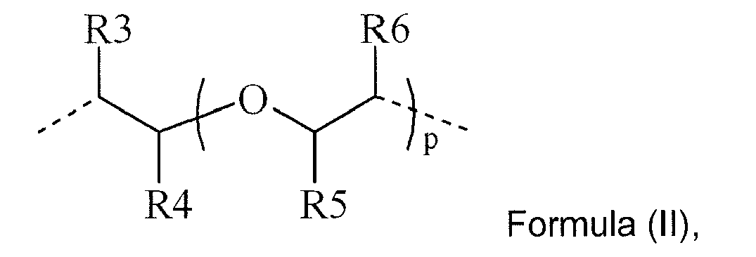
R3 to R6 independently represent hydrogen or a methyl group; and p represents an integer from 1 to 10. - In a preferred embodiment of the polymerizable Norrish Type II photoinitiator according to Formula (I), the integer n is 0.
- In a preferred embodiment of the polymerizable Norrish Type II photoinitiator according to Formula (I), the divalent linking group L2 represents an optionally substituted saturated alkylene group.
- In a preferred embodiment of the polymerizable Norrish Type II photoinitiator according to Formula (I), the group R2 represents hydrogen.
- In a more preferred embodiment of the polymerizable Norrish Type II photoinitiator according to Formula (I), the integer n is 0 and the divalent linking group L2 represents an optionally substituted saturated alkylene group.
- In a more preferred embodiment of the polymerizable Norrish Type II photoinitiator according to Formula (I), the integer n is 0 and the group R2 represents hydrogen.
- In a more preferred embodiment of the polymerizable Norrish Type II photoinitiator according to Formula (I), the divalent linking group L2 represents an optionally substituted saturated alkylene group and the group R2 represents hydrogen.
- In the most preferred embodiment of the polymerizable Norrish Type II photoinitiator according to Formula (I), the integer n is 0, the group R2 represents hydrogen and the divalent linking group L2 represents an optionally substituted saturated alkylene group.
- In one embodiment, the polymerizable Norrish Type II photoinitiator may contain 2, 3 or more ethylenically unsaturated polymerizable groups.
- In a preferred embodiment, the polymerizable Norrish Type II photoinitiator contains only one acrylate group, since multiple acrylate groups reduce the flexibility of a cured layer.
- Preferred polymerizable Norrish Type II initiators containing a thioxanthone group are given below in Table 1, without being limited thereto.
Table 1 
TX-1 
TX-2 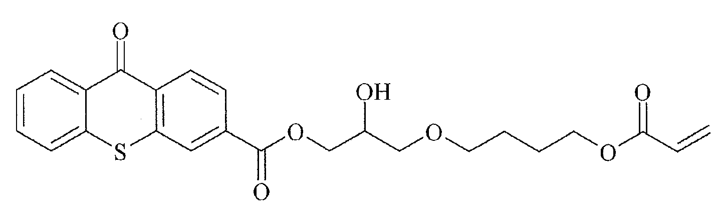
TX-3 
TX-4 
TX-5 
TX-6 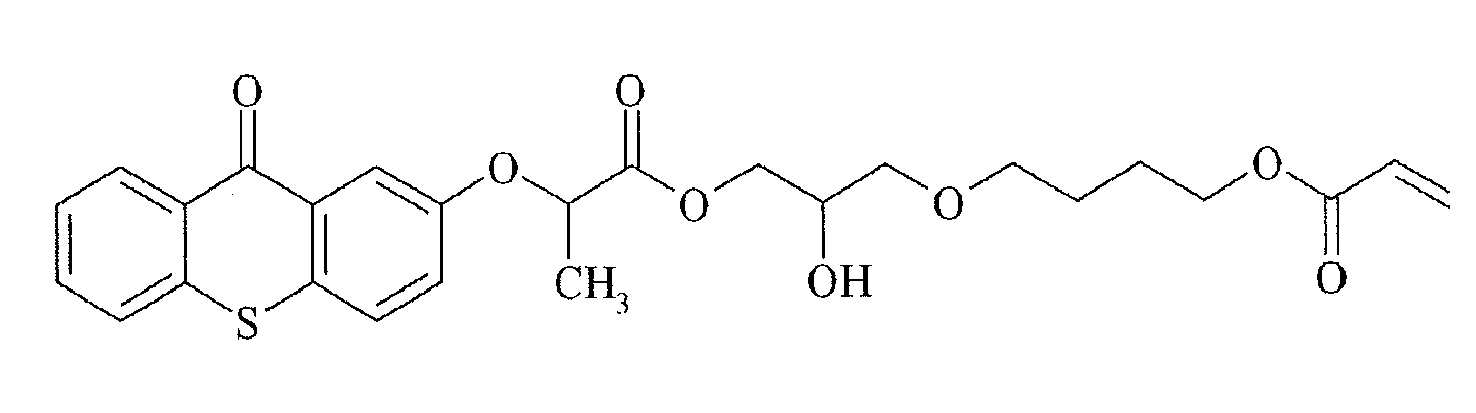
TX-7 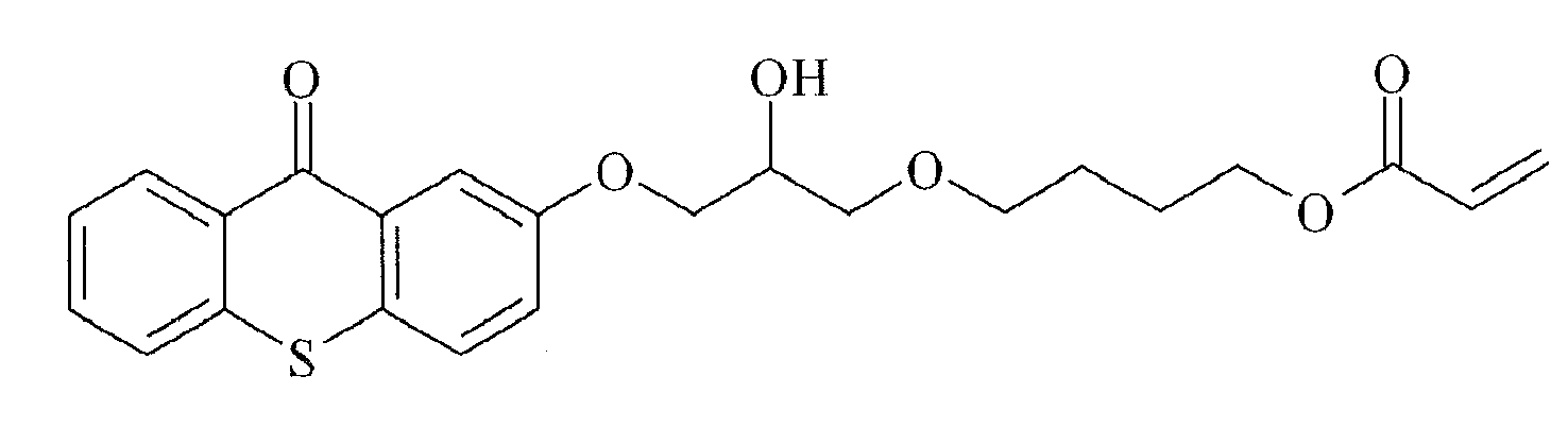
TX-8 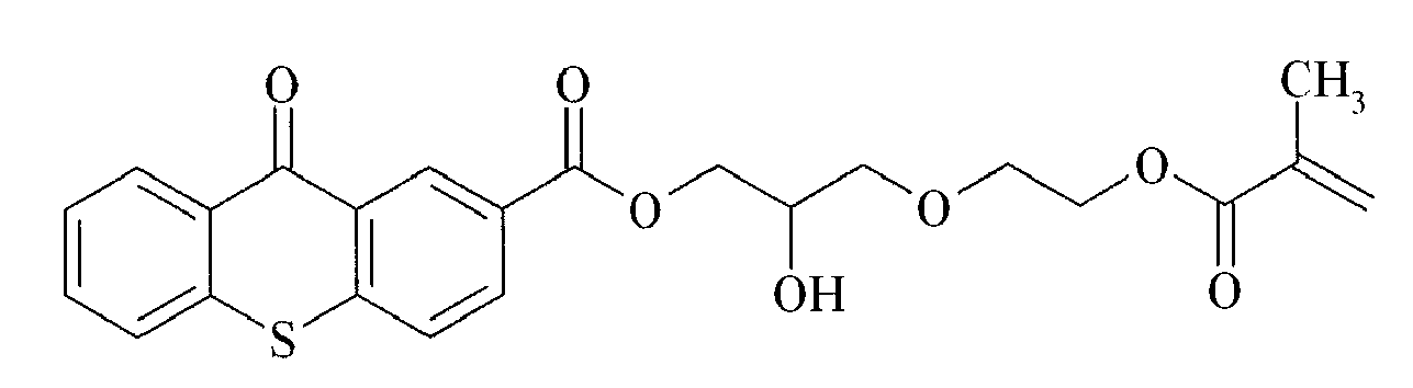
TX-9 
TX-10 
TX-11 
TX-12 - Preferred polymerizable Norrish Type II initiators containing a benzophenone group are given below in Table 2, without being limited thereto.
Table 2 
BP-1 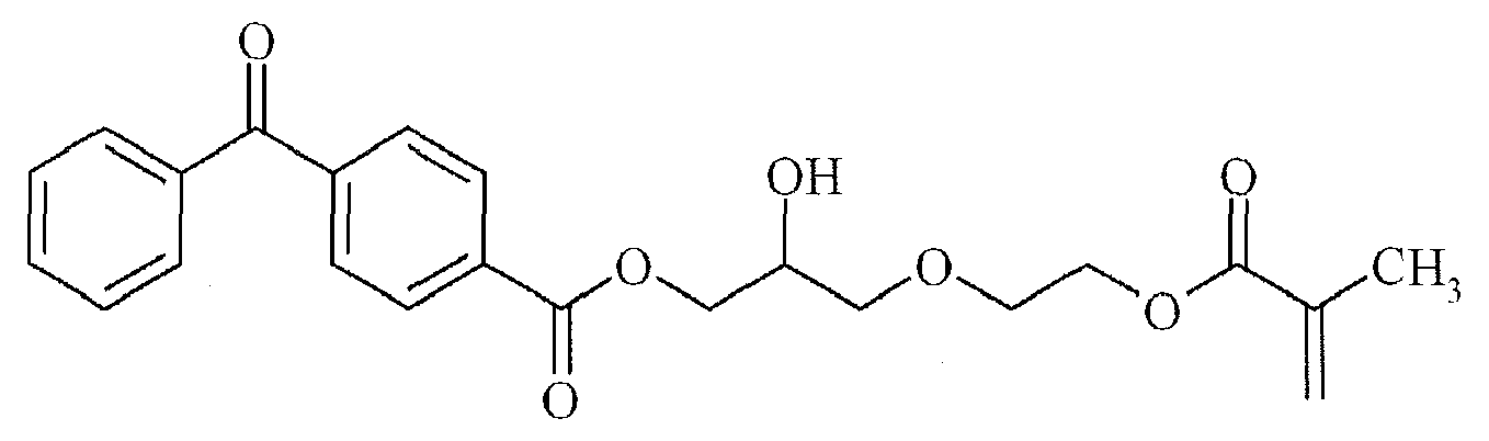
BP-2 
BP-3 
BP-4 
BP-5 - The radiation curable composition according to the present invention includes the polymerizable Norrish Type II-photoinitiator as defined above and a co-initiator. A preferred amount of the polymerizable Norrish Type II-photoinitiator is 1 to 50 wt%, more preferably 2 to 25 wt%, and most preferably 5 to 10 wt% of the total weight of the radiation curable composition. Combinations of type I and type II photoinitiators can be used in the radiation curable compositions according to the present invention.
- In the most preferred embodiment the radiation curable composition includes one or more monomers and/or oligomers.
- A preferred embodiment of radiation curable composition includes a polymerizable Norrish Type II-photoinitiator as defined above, a co-initiator and a polymerizable composition consisting essentially of:
- a) 25 - 100 wt% of one or more polymerizable compounds PA having at least one acrylate group G1 and at least one second ethylenically unsaturated polymerizable functional group G2 selected from the group consisting of a vinlyether group, an allylether group and a allylester group;
- b) 0 - 55 wt% of one or more polymerizable compounds PB selected from the group consisting of monofunctional acrylates and difunctional acrylates; and
- c) 0 - 55 wt% of one or more polymerizable compounds PC selected from the group consisting of trifunctional acrylates, tetrafunctional acrylates, pentafunctional acrylates and hexafunctional acrylates, with the proviso that if the weight percentage of compounds PB > 24 wt%, then the weight percentage of compounds PC > 1 wt%;
and wherein all weight percentages of PA, PB and PC are based upon the total weight of the polymerizable composition. - Examples of the latter radiation curable compositions are disclosed in the unpublished
EP071191710 A - The radiation curable compositions and inks are preferably cured by UV radiation and are preferably radiation curable inkjet liquids or inks. The radiation curable compositions and inks can also be advantageously used in offset printing, screen printing, flexographic printing and other printing or coating techniques.
- The radiation curable compositions and inks are preferably non-aqueous liquids or inks. The term "non-aqueous" refers to a liquid carrier which should contain no water. However sometimes a small amount, generally less than 5 wt% of water based on the total weight of the composition or ink, can be present. This water was not intentionally added but came into the formulation via other components as a contamination, such as for example polar organic solvents. Higher amounts of water than 5 wt% tend to make the non-aqueous liquids and inks instable, preferably the water content is less than 1 wt% based on the total weight of radiation curable composition or ink and most preferably no water at all is present.
- The radiation curable compositions and inks preferably do not contain an evaporable component such as an organic solvent. But sometimes it can be advantageous to incorporate a small amount of an organic solvent to improve adhesion to the surface of a substrate after UV-curing. In this case, the added solvent can be any amount in the range that does not cause problems of solvent resistance and VOC, and preferably 0.1 - 10.0 wt%, and particularly preferably 0.1 - 5.0 wt%, each based on the total weight of the curable composition or ink.
- The radiation curable compositions and inks are preferably part of an ink set, more preferably an inkjet ink set, comprising at least one ink containing one or more colorants, preferably one or more colour pigments. The curable ink set preferably comprises at least one yellow curable ink (Y), at least one cyan curable ink (C) and at least one magenta curable ink (M) and preferably also at least one black curable ink (K). The curable CMYK-ink set may also be extended with extra inks such as red, green, blue, and/or orange to further enlarge the colour gamut of the image. The CMYK-ink set may also be extended by the combination of full density and light density inks of both colour inks and/or black inks to improve the image quality by lowered graininess.
- The pigmented radiation curable ink preferably contains a dispersant, more preferably a polymeric dispersant, for dispersing the pigment. The pigmented curable ink may contain a dispersion synergist to improve the dispersion quality and stability of the ink. Preferably, at least the magenta ink contains a dispersion synergist. A mixture of dispersion synergists may be used to further improve dispersion stability.
- The viscosity of the curable liquid and ink is preferably smaller than 100 mPa.s at 30°C and at a shear rate of 100 s-1. The viscosity of the radiation curable inkjet inks and liquids is preferably smaller than 50 mPa.s, more preferably lower than 30 mPa.s, and most preferably between 2 and 15 mPa.s at a shear rate of 100 s-1 and a jetting temperature between 10 and 70°C. In a more preferred embodiment, the viscosity of the radiation curable inkjet inks and liquids is preferably smaller than 50 mPa.s, more preferably lower than 30 mPa.s, and most preferably between 2 and 15 mPa.s at a shear rate of 100 s-1 and a jetting temperature of 25°C.
- The surface tension of the curable liquid and ink is preferably in the range of about 20 mN/m to about 70 mN/m at 25°C, more preferably in the range of about 22 mN/m to about 40 mN/m at 25°C.
- The curable composition or ink may further also contain at least one inhibitor for improving the thermal stability of composition or ink
- The curable composition or ink may further also contain at least one surfactant for obtaining good spreading characteristics on a substrate.
- The radiation curable composition according to the present invention contains at least one co-initiator, but may contain a mixture of 2, 3 or more co-initiators. A preferred amount of the co-initiator is 1 to 30 wt%, more preferably 2 to 20 wt%, and most preferably 5 to 10 wt% of the total weight of the radiation curable composition.
- For safety reasons, in particular for food packaging applications, the radiation curable composition according to the present invention contains at least one so-called diffusion hindered co-initiator. A diffusion hindered co-initiator is a co-initiator which exhibits a much lower mobility in a cured layer of the radiation curable composition or ink than a monofunctional, non-polymerizable co-initiator, such as a dialkylaminobenzoate. Several methods can be used to lower the mobility of the photoinitiator. One way is to increase the molecular weight of the co-initiator so that the diffusion speed is reduced, e.g. multifunctional co-initiators or polymeric co-initiators. Another way is to increase its reactivity so that it is built into the polymerizing network, e.g. multifunctional co-initiators and polymerizable co-initiators.
- The diffusion hindered co-initiator is preferably selected from the group consisting of non-polymeric di- or multifunctional co-initiators, oligomeric or polymeric co-initiators and polymerizable co-initiators. Non-polymeric di- or multifunctional co-initiators usually have a molecular weight between 300 and 900 Dalton. Monofunctional co-initiators with a molecular weight in that range are not diffusion hindered co-initiators.
- In a preferred embodiment of the radiation curable composition according to the present invention, the at least one co-initiator is a diffusion hindered dialkylamino substituted aromatic compound selected from the group consisting of an oligomeric or polymeric dialkylamino substituted aromatic compound, a multifunctional dialkylamino substituted aromatic compound and a dialkylamino substituted aromatic compound comprising at least one polymerizable ethylenically unsatured group. A dialkylamino substituted aromatic compound comprising at least one polymerizable ethylenically unsatured group is particularly preferred.
- In a more preferred embodiment the dialkylamino substituted aromatic compound comprising at least one polymerizable ethylenically unsatured group is a co-initiator according to Formula (III):
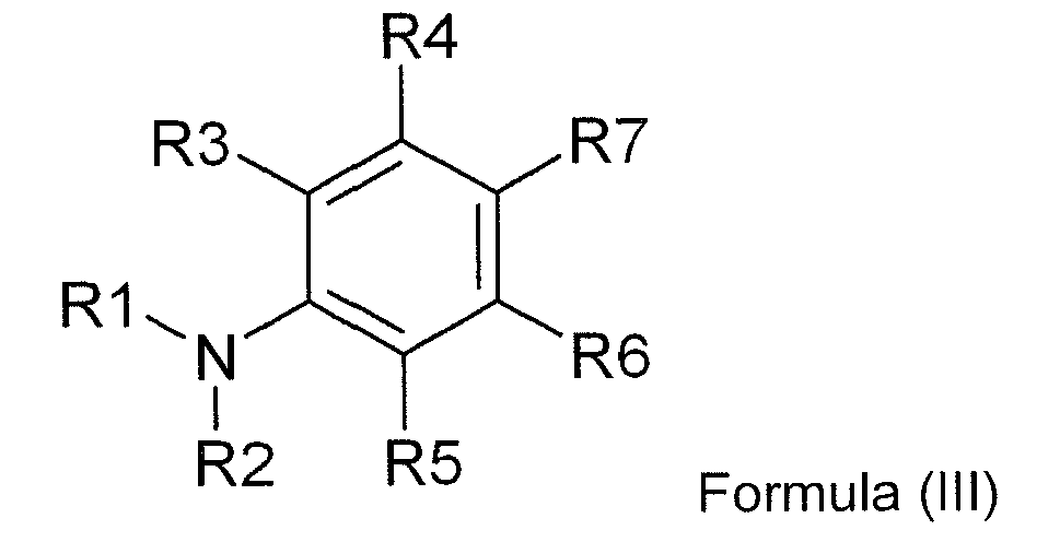
R1 and R2 are independently selected from the group consisting of an alkyl group, an alkenyl group, an alkynyl group, an aralkyl group, an alkaryl group, an aryl group and a heteroaryl group;
R3 to R6 are independently selected from the group consisting of hydrogen, an alkyl group, an alkenyl group, an alkynyl group, an acyl group, a thioalkyl group, an alkoxy group, a halogen, an aralkyl group, an alkaryl group, an aryl group and a heteroaryl group;
R7 is selected from the group consisting of hydrogen, an aldehyde group, a ketone group, an ester group, an amide group, an acyl group, a thioalkyl group, an alkoxy group, a halogen, a nitrile group, a sulphonate group, a sulphonamide group, an alkyl group, an alkenyl group, an alkynyl group, an aralkyl group, an alkaryl group, an aryl group and a heteroaryl group; R1 and R2, R1 and R3, R2 and R5, R3 and R4, R4 and R7, R5 and R6, and R6 and R7 may represent the necessary atoms to form a 5- to 8-membered ring; and with the proviso that the aromatic amine has at least one α-hydrogen; and
at least one of R1 to R7 comprises a polymerizable ethylenically unsaturated functional group selected from the group consisting of acrylate, substituted acrylate, methacrylate, styrene, acrylamide, methacrylamide, allyl ester, allyl ether, vinyl ester, vinyl ether, fumarate, maleate, maleimide and vinyl nitrile. In the polymerizable co-initiator, preferably R7 represents an electron withdrawing group selected from the group consisting of an aldehyde, a ketone, an ester and an amide, and more preferably R3, R4, R5 and R6 all represent hydrogen. - The alkyl groups, alkenyl groups, alkynyl groups, aralkyl groups, alkaryl groups, aryl groups and heteroaryl groups used for R1 to R7 can be substituted or unsubstituted groups, i.e. a substituted or unsubstituted alkyl group, a substituted or unsubstituted alkenyl group, a substituted or unsubstituted alkynyl group, a substituted or unsubstituted aralkyl group, a substituted or unsubstituted alkaryl group and a substituted or unsubstituted (hetero)aryl group may be used.
- In a preferred embodiment, the polymerizable co-initiator corresponds to Formula (IV):

R1 to R6 have the same meaning as defined for Formula (IV);
X is selected from the group consisting of O, S and NR9;
R8 and R9 are independently selected from the group consisting of hydrogen, an alkyl group, an alkenyl group, an alkynyl group, an aralkyl group, an alkaryl group, an aryl group and a heteroaryl group;
R1 and R2, R1 and R3, R2 and R5, R3 and R4, R5 and R6, R4 and R8, R6 and R8, and R8 and R9 may represent the necessary atoms to form a 5- to 8-membered ring; and at least one of R1 to R6 and R8 comprises a polymerizable ethylenically unsaturated functional group selected from the group consisting of acrylate, substituted acrylate, methacrylate, styrene, acrylamide, methacrylamide, allyl ester, allyl ether, vinyl ester, vinyl ether, fumarate, maleate, maleimide and vinyl nitrile. In the polymerizable co-initiator, preferably R3, R4, R5 and R6 all represent hydrogen. - In one preferred embodiment of the polymerizable co-initiator having Formula (IV), R1 represents methyl or ethyl and R2 comprises a polymerizable ethylenically unsaturated functional group selected from the group consisting of acrylate, substituted acrylate, methacrylate, styrene, acrylamide, methacrylamide, allyl ester, allyl ether, vinyl ester, vinyl ether, fumarate, maleate, maleimide and vinyl nitrile; and more preferably also R3, R4, R5 and R6 all represent hydrogen.
- In another preferred embodiment of the polymerizable co-initiator having Formula (IV), R1 and R2 independently represent methyl or ethyl and R8 comprises a polymerizable ethylenically unsaturated functional group selected from the group consisting of acrylate, substituted acrylate, methacrylate, styrene, acrylamide, methacrylamide, allyl ester, allyl ether, vinyl ester, vinyl ether, fumarate, maleate, maleimide and vinyl nitrile; and more preferably also R3, R4, R5 and R6 all represent hydrogen.
- In a more preferred embodiment, the polymerizable co-initiator corresponds to Formula (V):
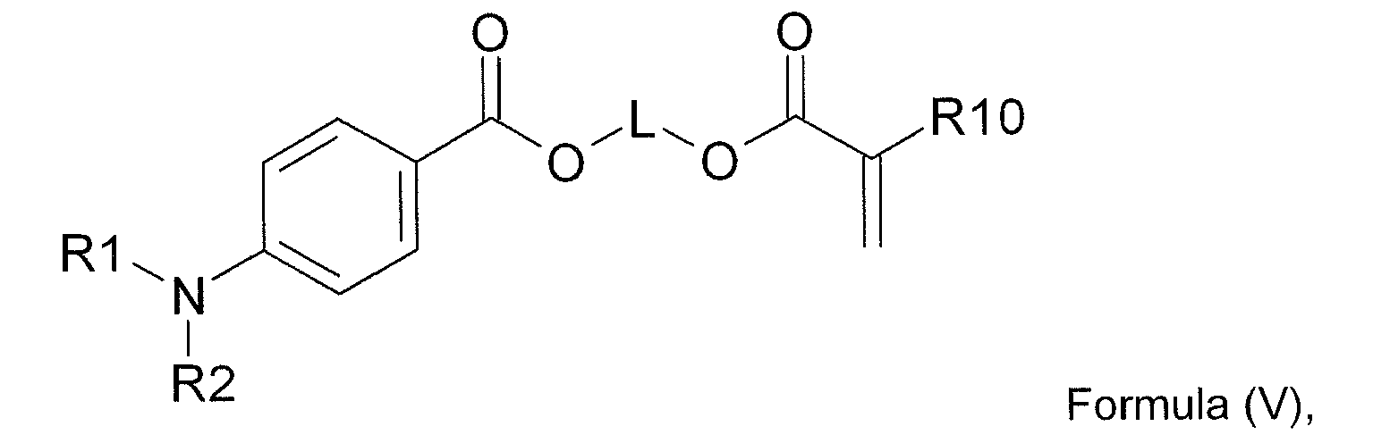
R1 and R2 are independently selected from the group consisting of methyl, ethyl, propyl and butyl;
L represents a divalent linking group comprising at least one carbon atom; and
R10 represents hydrogen, methyl, ethyl, propyl or butyl. - In a preferred embodiment of the polymerizable co-initiator corresponding to Formula (V), the divalent linking group L comprises 1 to 30 carbon atoms, more preferably 2 to 10 carbon atoms and most preferably 3 to 6 atoms.
- The polymerizable co-initiator may contain two, three or more polymerizable ethylenically unsaturated functional groups independently selected from the group consisting of acrylate, substituted acrylate, methacrylate, styrene, acrylamide, methacrylamide, allyl ester, allyl ether, vinyl ester, vinyl ether, fumarate, maleate, maleimide and vinyl nitrile.
- The polymerizable co-initiator may also contain more than one tertiary amine functional group, preferably the second or third tertiary amine functional group is also an aromatic tertiary amine, most preferably a dialkylamino benzoic acid derivative.
- Examples of diffusion hindered co-initiators are given in Table 3 without being limited thereto. Suitable examples of oligomeric and polymeric dialkylamino substituted aromatic compounds are COINI-1 to COINI-3. Suitable examples of multifunctional dialkylamino substituted aromatic compounds are co-initiators COINI-4 to COINI-11. Suitable polymerizable co-initiators are co-initiators COINI-12 to COINI-26.
Table 3 COINI-1 
COINI-2 
COINI-3 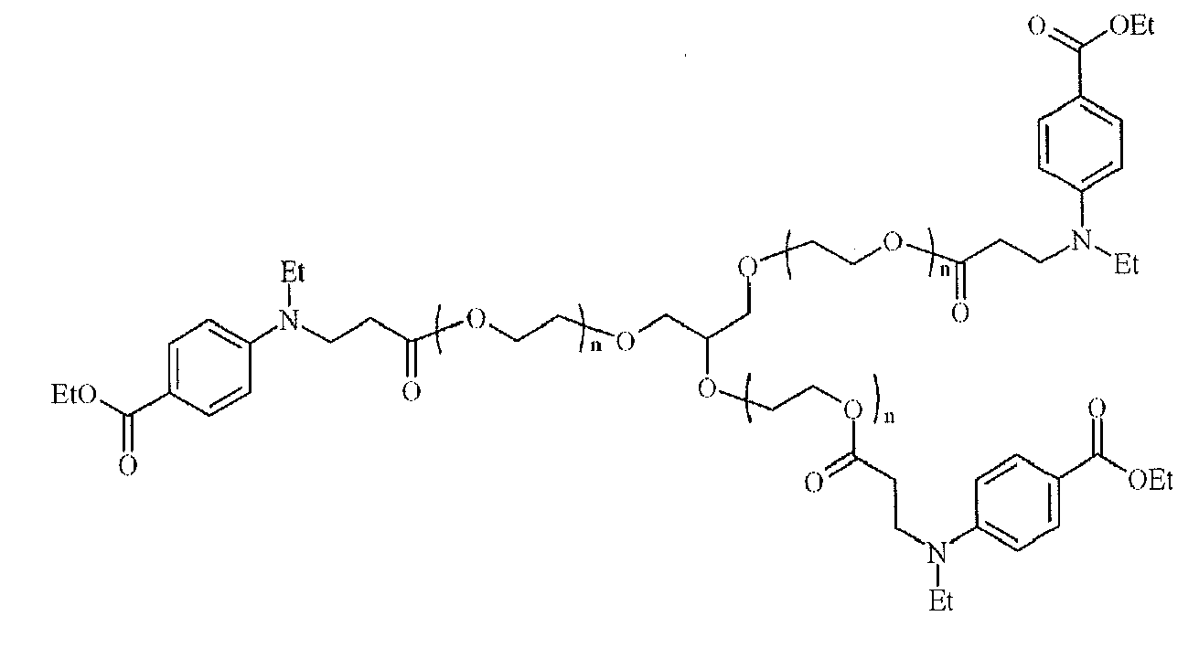
COINI-4 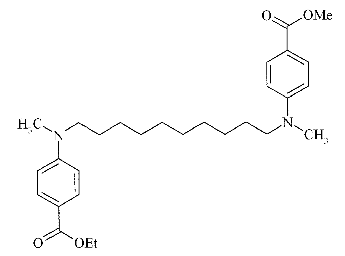
COINI-5 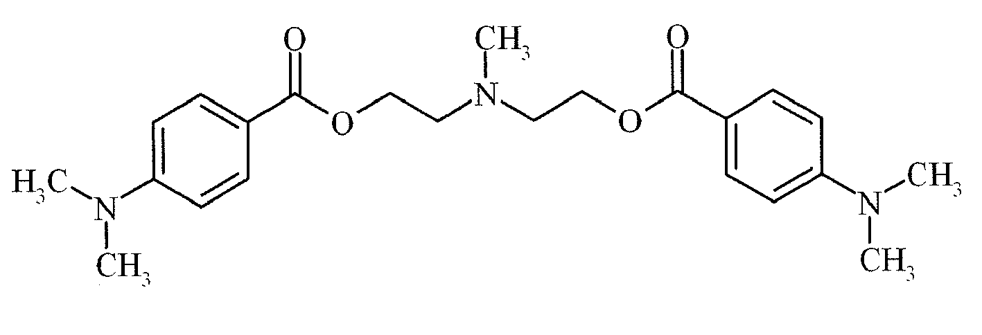
COINI-6 
COINI-7 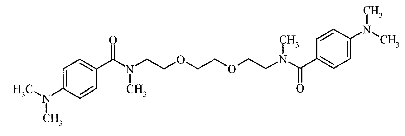
COINI-8 
COINI-9 
COINI-10 
COINI-11 
COINI-12 
COINI-13 
COINI-14 
COINI-15 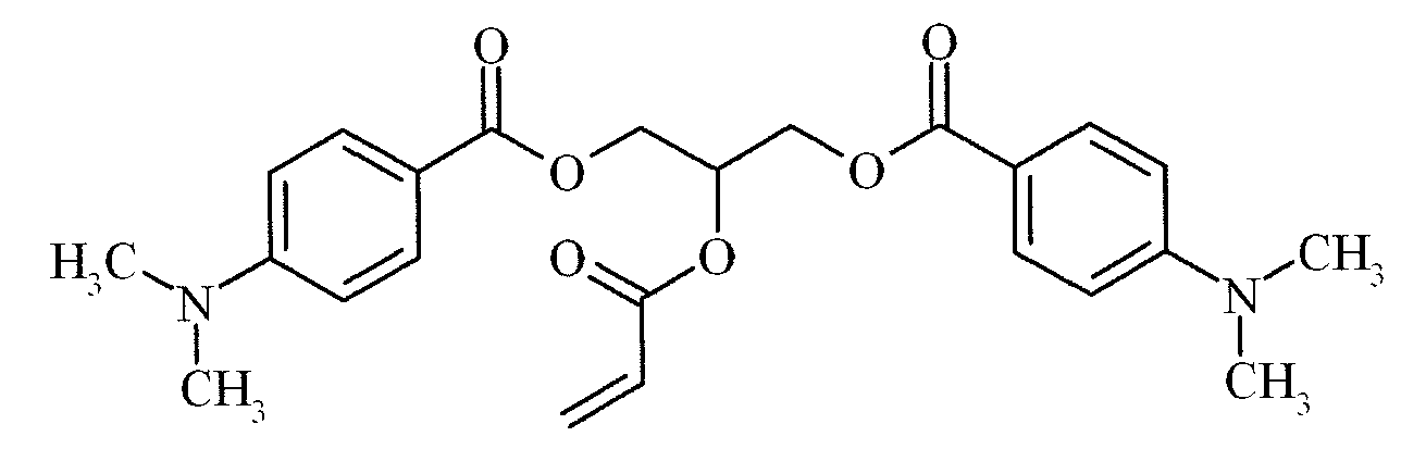
COINI-16 
COINI-17 
COINI-18 
COINI-19 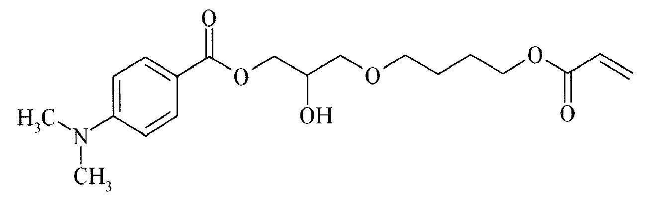
COINI-20 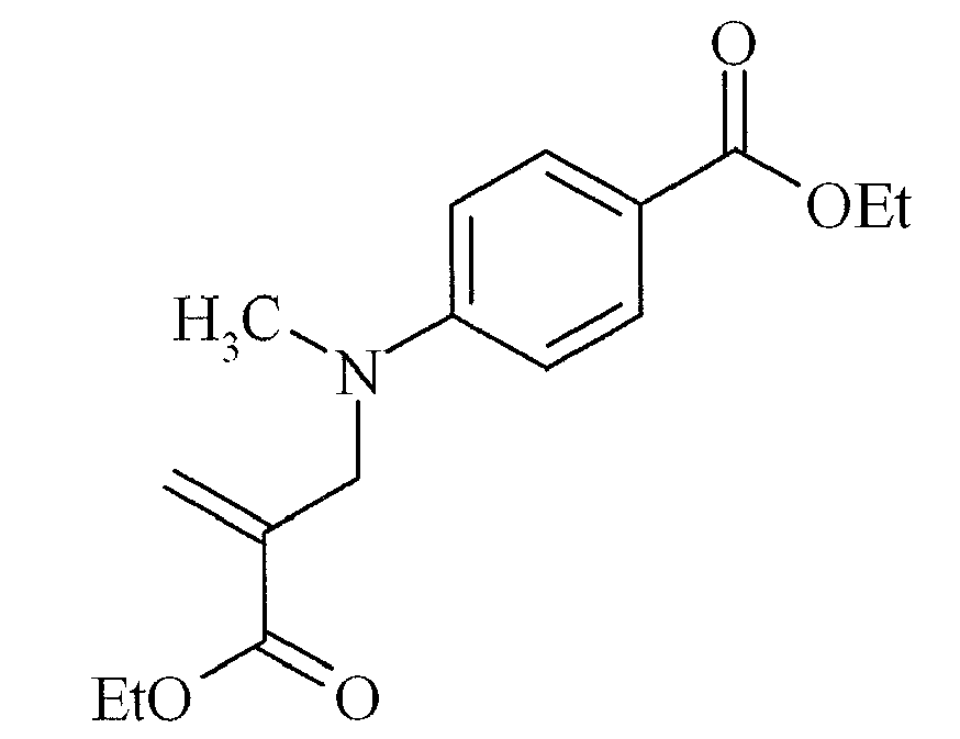
COINI-21 
COINI-22 
COINI-23 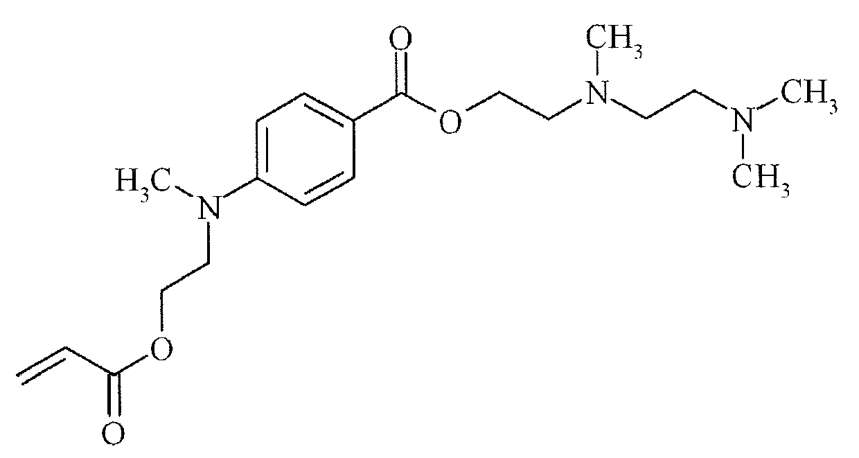
COINI-24 
COINI-25 
COINI-26 
- The monomers and oligomers used in the radiation curable compositions and inks, especially for food packaging applications, are preferably purified compounds having no or almost no impurities, more particularly no toxic or carcinogenic impurities. The impurities are usually derivative compounds obtained during synthesis of the polymerizable compound. Sometimes, however, some compounds may be added deliberately to pure polymerizable compounds in harmless amounts, for example, polymerization inhibitors or stabilizers.
- Any monomer or oligomer capable of free radical polymerization may be used as polymerizable compound. A combination of monomers, oligomers and/or prepolymers may also be used. The monomers, oligomers and/or prepolymers may possess different degrees of functionality, and a mixture including combinations of mono-, di-, tri-and higher functionality monomers, oligomers and/or prepolymers may be used. The viscosity of the radiation curable compositions and inks can be adjusted by varying the ratio between the monomers and oligomers.
- Particularly preferred monomers and oligomers are those listed in [0106] to [0115] in
EP1911814 A (AGFA GRAPHICS) incorporated herein as a specific reference. - A preferred class of monomers and oligomers are vinyl ether acrylates such as those described in
US 6310115 (AGFA) , incorporated herein by reference. Particularly preferred compounds are 2- (2-vinyloxyethoxy)ethyl (meth)acrylate, most preferably the compound is 2- (2-vinyloxyethoxy)ethyl acrylate. - The radiation curable compositions and inks may contain a polymerization inhibitor. Suitable polymerization inhibitors include phenol type antioxidants, hindered amine light stabilizers, phosphor type antioxidants, hydroquinone monomethyl ether commonly used in (meth)acrylate monomers, and hydroquinone, t-butylcatechol, pyrogallol, 2,6-di-tert.butyl-4-methylphenol may also be used.
- Suitable commercial inhibitors are, for example, Sumilizer™ GA-80, Sumilizer™ GM and Sumilizer™ GS produced by Sumitomo Chemical Co. Ltd.; Genorad™ 16, Genorad™ 18 and Genorad™ 20 from Rahn AG; Irgastab™ UV10 and Irgastab™ UV22, Tinuvin™ 460 and CGS20 from Ciba Specialty Chemicals; Floorstab™ UV range (UV-1, UV-2, UV-5 and UV-8) from Kromachem Ltd, Additol™ S range (S100, S110, S120 and S130) from Cytec Surface Specialties.
- The inhibitor is preferably a polymerizable inhibitor.
- Since excessive addition of these polymerization inhibitors may lower the curing speed, it is preferred that the amount capable of preventing polymerization is determined prior to blending. The amount of a polymerization inhibitor is preferably lower than 5 wt%, more preferably lower than 3 wt% of the total ink or liquid.
- The radiation curable compositions and inks may contain a surfactant. The surfactant(s) can be anionic, cationic, non-ionic, or zwitter-ionic and are usually added in a total quantity less than 10 wt% based on the total weight of the radiation curable compositions or ink and particularly in a total less than 5 wt% based on the total weight of the radiation curable composition or ink.
- Suitable surfactants include those disclosed in paragraphs [0283] to [0291] of
WO 2008/074548 (AGFA GRAPHICS) incorporated herein as a specific reference. - Colorants used in the radiation curable inks may be dyes, pigments or a combination thereof. Organic and/or inorganic pigments may be used. The colorant is preferably a pigment or a polymeric dye, most preferably a pigment.
- The pigments may be black, white, cyan, magenta, yellow, red, orange, violet, blue, green, brown, mixtures thereof, and the like. This colour pigment may be chosen from those disclosed by HERBST, Willy, et al. Industrial Organic Pigments, Production, Properties, Applications. 3rd edition. Wiley - VCH , 2004. ISBN 3527305769.
- Suitable pigments are disclosed in paragraphs [0128] to [0138] of
WO 2008/074548 (AGFA GRAPHICS) . - Suitable pigments include mixed crystals of the above particular preferred pigments. Mixed crystals are also referred to as solid solutions. For example, under certain conditions different quinacridones mix with each other to form solid solutions, which are quite different from both physical mixtures of the compounds and from the compounds themselves. In a solid solution, the molecules of the components enter into the same crystal lattice, usually, but not always, that of one of the components. The x-ray diffraction pattern of the resulting crystalline solid is characteristic of that solid and can be clearly differentiated from the pattern of a physical mixture of the same components in the same proportion. In such physical mixtures, the x-ray pattern of each of the components can be distinguished, and the disappearance of many of these lines is one of the criteria of the formation of solid solutions. A commercially available example is Cinquasia Magenta RT-355-D from Ciba Specialty Chemicals.
- Also mixtures of pigments may be used in the radiation curable inks. For some inkjet applications, a neutral black inkjet ink is preferred and can be obtained, for example, by mixing a black pigment and a cyan pigment into the ink. The inkjet application may also require one or more spot colours, for example for packaging inkjet printing or textile inkjet printing. Silver and gold are often desired colours for inkjet poster printing and point-of-sales displays.
- Non-organic pigments may be used in the colour inkjet inks. Particular preferred pigments are C.I. Pigment Metal 1, 2 and 3. Illustrative examples of the inorganic pigments include red iron oxide (III), cadmium red, ultramarine blue, prussian blue, chromium oxide green, cobalt green, amber, titanium black and synthetic iron black.
- Pigment particles in inkjet inks should be sufficiently small to permit free flow of the ink through the inkjet-printing device, especially at the ejecting nozzles. It is also desirable to use small particles for maximum colour strength and to slow down sedimentation.
- The numeric average pigment particle size is preferably between 0.050 and 1 µm, more preferably between 0.070 and 0.300 µm and particularly preferably between 0.080 and 0.200 µm. Most preferably, the numeric average pigment particle size is no larger than 0.150 µm. An average particle size smaller than 0.050 µm is less desirable for decreased lightfastness, but mainly also because very small pigment particles or individual pigment molecules thereof may still be extracted in food packaging applications. The average particle size of pigment particles is determined with a Brookhaven Instruments Particle Sizer B190plus based upon the principle of dynamic light scattering. The ink is diluted with ethyl acetate to a pigment concentration of 0.002 wt%. The measurement settings of the B190plus are: 5 runs at 23°C, angle of 90°, wavelength of 635 nm and graphics = correction function
- However for a white radiation curable ink, the numeric average particle diameter of the white pigment is preferably from 50 to 500 nm, more preferably from 150 to 400 nm, and most preferably from 200 to 350 nm. Sufficient hiding power cannot be obtained when the average diameter is less than 50 nm, and the storage ability and the jet-out suitability of the ink tend to be degraded when the average diameter exceeds 500 nm. The determination of the numeric average particle diameter is best performed by photon correlation spectroscopy at a wavelength of 633 nm with a 4mW HeNe laser on a diluted sample of the pigmented inkjet ink. A suitable particle size analyzer used was a Malvern™ nano-S available from Goffin-Meyvis. A sample can be, for example, be prepared by addition of one drop of ink to a cuvet containing 1.5 mL ethyl acetate and mixed until a homogenous sample was obtained. The measured particle size is the average value of 3 consecutive measurements consisting of 6 runs of 20 seconds.
- Suitable white pigments are given by Table 2 in [0116] of
WO 2008/074548 (AGFA GRAPHICS). The white pigment is preferably a pigment with a refractive index greater than 1.60. The white pigments may be employed singly or in combination. Preferably titanium dioxide is used as pigment with a refractive index greater than 1.60. Suitable titanium dioxide pigments are those disclosed in [0117] and in [0118] ofWO 2008/074548 (AGFA GRAPHICS). - The pigments are present in the range of 0.01 to 10 % by weight, preferably in the range of 0.1 to 5 % by weight, each based on the total weight of radiation curable ink. For white radiation curable inks, the white pigment is preferably present in an amount of 3% to 30% by weight of the ink composition, and more preferably 5% to 25%. An amount of less than 3% by weight cannot achieve sufficient covering power and usually exhibits very poor storage stability and ejection property.
- Generally pigments are stabilized in the dispersion medium by dispersing agents, such as polymeric dispersants. However, the surface of the pigments can be modified to obtain so-called "self-dispersible" or "self-dispersing" pigments, i.e. pigments that are dispersible in the dispersion medium without dispersants.
- The dispersant is preferably a polymeric dispersant. Typical polymeric dispersants are copolymers of two monomers but may contain three, four, five or even more monomers. The properties of polymeric dispersants depend on both the nature of the monomers and their distribution in the polymer. Suitable copolymeric dispersants have the following polymer compositions:
- statistically polymerized monomers (e.g. monomers A and B polymerized into ABBAABAB);
- alternating polymerized monomers (e.g. monomers A and B polymerized into ABABABAB);
- gradient (tapered) polymerized monomers (e.g. monomers A and B polymerized into AAABAABBABBB);
- block copolymers (e.g. monomers A and B polymerized into AAAAABBBBBB) wherein the block length of each of the blocks (2, 3, 4, 5 or even more) is important for the dispersion capability of the polymeric dispersant;
- graft copolymers (graft copolymers consist of a polymeric backbone with polymeric side chains attached to the backbone); and
- mixed forms of these polymers, e.g. blocky gradient copolymers.
- Suitable polymeric dispersants are listed in the section on "Dispersants", more specifically [0064] to [0070] and [0074] to [0077], in
EP 1911814 A (AGFA GRAPHICS) incorporated herein as a specific reference. - The polymeric dispersant has preferably a number average molecular weight Mn between 500 and 30000, more preferably between 1500 and 10000.
- The polymeric dispersant has preferably a weight average molecular weight Mw smaller than 100000, more preferably smaller than 50000 and most preferably smaller than 30000.
- The polymeric dispersant has preferably a polydispersity PD smaller than 2, more preferably smaller than 1.75 and most preferably smaller than 1.5.
- Commercial examples of polymeric dispersants are the following:
- DISPERBYK™ dispersants available from BYK CHEMIE GMBH;
- SOLSPERSE™ dispersants available from NOVEON;
- TEGO™ DISPERS™ dispersants from DEGUSSA;
- EDAPLAN™ dispersants from MÜNZING CHEMIE;
- ETHACRYL™ dispersants from LYONDELL;
- GANEX™ dispersants from ISP;
- DISPEX™ and EFKA™ dispersants from CIBA SPECIALTY CHEMICALS INC;
- DISPONER™ dispersants from DEUCHEM; and
- JONCRYL™ dispersants from JOHNSON POLYMER.
- Particularly preferred polymeric dispersants include Solsperse™ dispersants from NOVEON, Efka™ dispersants from CIBA SPECIALTY CHEMICALS INC and Disperbyk™ dispersants from BYK CHEMIE GMBH. Particularly preferred dispersants are Solsperse™ 32000, 35000 and 39000 dispersants from NOVEON.
- The polymeric dispersant is preferably used in an amount of 2 to 600 wt%, more preferably 5 to 200 wt% based on the weight of the pigment.
- A dispersion synergist usually consists of an anionic part and a cationic part. The anionic part of the dispersion synergist exhibiting a certain molecular similarity with the colour pigment and the cationic part of the dispersion synergist consists of one or more protons and/or cations to compensate the charge of the anionic part of the dispersion synergist.
- The synergist is preferably added in a smaller amount than the polymeric dispersant(s). The ratio of polymeric dispersant/dispersion synergist depends upon the pigment and should be determined experimentally. Typically the ratio wt% polymeric dispersant/wt% dispersion synergist is selected between 2:1 to 100:1, preferably between 2:1 and 20:1.
- Suitable dispersion synergists that are commercially available include Solsperse™ 5000 and Solsperse™ 22000 from NOVEON.
- Particular preferred pigments for the magenta ink used are a diketopyrrolopyrrole pigment or a quinacridone pigment. Suitable dispersion synergists include those disclosed in
EP1790698 A (AGFA GRAPHICS),EP 1790696 A (AGFA GRAPHICS),WO 2007/060255 (AGFA GRAPHICS) andEP1790695 A (AGFA GRAPHICS). - In dispersing C.I. Pigment Blue 15:3, the use of a sulfonated Cu-phthalocyanine dispersion synergist, e.g. Solsperse™ 5000 from NOVEON is preferred. Suitable dispersion synergists for yellow inkjet inks include those disclosed in
EP 1790697 A (AGFA GRAPHICS). - The average particle size and distribution is an important feature for inkjet inks. The ink may be prepared by precipitating or milling the pigment in the dispersion medium in the presence of the dispersant.
- Mixing apparatuses may include a pressure kneader, an open kneader, a planetary mixer, a dissolver, and a Dalton Universal Mixer. Suitable milling and dispersion apparatuses are a ball mill, a pearl mill, a colloid mill, a high-speed disperser, double rollers, a bead mill, a paint conditioner, and triple rollers. The dispersions may also be prepared using ultrasonic energy.
- Many different types of materials may be used as milling media, such as glasses, ceramics, metals, and plastics. In a preferred embodiment, the grinding media can comprise particles, preferably substantially spherical in shape, e.g. beads consisting essentially of a polymeric resin or yttrium stabilized zirconium oxide beads.
- In the process of mixing, milling and dispersion, each process is performed with cooling to prevent build up of heat, and for radiation curable inks as much as possible under light conditions in which actinic radiation has been substantially excluded.
- The ink may contain more than one pigment, the ink may be prepared using separate dispersions for each pigment, or alternatively several pigments may be mixed and co-milled in preparing the dispersion.
- The dispersion process can be carried out in a continuous, batch or semi-batch mode.
- The preferred amounts and ratios of the ingredients of the mill grind will vary widely depending upon the specific materials and the intended applications. The contents of the milling mixture comprise the mill grind and the milling media. The mill grind comprises pigment, polymeric dispersant and a liquid carrier. For inkjet inks, the pigment is usually present in the mill grind at 1 to 50 wt%, excluding the milling media. The weight ratio of pigment over polymeric dispersant is 20:1 to 1:2.
- The milling time can vary widely and depends upon the pigment, selected mechanical means and residence conditions, the initial and desired final particle size, etc. In the present invention pigment dispersions with an average particle size of less than 100 nm may be prepared.
- After milling is completed, the milling media is separated from the milled particulate product (in either a dry or liquid dispersion form) using conventional separation techniques, such as by filtration, sieving through a mesh screen, and the like. Often the sieve is built into the mill, e.g. for a bead mill. The milled pigment concentrate is preferably separated from the milling media by filtration.
- In general it is desirable to make the inks in the form of a concentrated mill grind, which is subsequently diluted to the appropriate concentration for use in the printing system. This technique permits preparation of a greater quantity of pigmented ink from the equipment. By dilution, the ink is adjusted to the desired viscosity, surface tension, colour, hue, saturation density, and print area coverage for the particular application.
- The inkjet printing method according to the present invention comprises the steps of:
- a) providing a radiation curable composition according to the present invention; and
- b) at least partially curing the radiation curable composition.
- In a preferred embodiment of the inkjet printing method according to the present invention, the radiation curable composition is applied to a substrate by inkjet printing or by flexographic printing. For example, the radiation curable composition is applied as a primer on a substrate by flexographic printing and at least partially cured, and then a solvent inkjet ink or radiation curable inkjet ink is printed on the at least partially cured primer.
- In one embodiment of the inkjet printing method, the applied layer is a white primer, preferably containing a titanium dioxide pigment. White primers can be advantageously used, for example, on transparent substrates to enhance the contrast and the vividness of colour inks. White curable inks are then either used for so-called "surface printing" or "backing printing" to form a reflection image on a transparent substrate. In surface printing, a white background is formed on a transparent substrate using a white ink and further thereon, a colour image is printed, where after the formed final image is viewed from the printed face. In so-called backing printing, a colour image is formed on a transparent substrate using colour inks and then a white ink is applied onto the colour inks, and the final formed image is observed through the transparent substrate. In a preferred embodiment a colour inkjet ink is jetted on partially cured white inkjet ink. If the white ink is only partially cured, an improved wettability of the colour ink on the white ink layer is observed. Partially curing immobilizes the ink on the substrate surface. A quick test to verify that the white inkjet ink is partially cured can be done by rubbing a finger or a cloth across the printed surface, whereby it is observed that ink can be smeared or smudged on the surface.
- In another preferred embodiment of the inkjet printing method, the applied layer is a colourless layer. This layer can be present as a primer, for example, for improving the adhesion of the image, or as an outermost layer, for example, for improving the glossiness of the image.
- The above layers are preferably applied by a printing technique selected from the group consisting of inkjet printing, flexographic printing, offset printing and screen printing.
- Alternatively, above layers are applied by a coating technique selected from the group consisting of dip coating, knife coating, extrusion coating, spin coating, slide hopper coating and curtain coating.
- Curable compositions and inks according to the present invention may be jetted by one or more print heads ejecting small droplets of ink in a controlled manner through nozzles onto an ink-receiver surface, which is moving relative to the print head(s).
- A preferred print head for the inkjet printing system is a piezoelectric head. Piezoelectric inkjet printing is based on the movement of a piezoelectric ceramic transducer when a voltage is applied thereto. The application of a voltage changes the shape of the piezoelectric ceramic transducer in the print head creating a void, which is then filled with ink. When the voltage is again removed, the ceramic expands to its original shape, ejecting a drop of ink from the print head. However the inkjet printing method according to the present invention is not restricted to piezoelectric inkjet printing. Other inkjet print heads can be used and include various types, such as a continuous type and thermal, electrostatic and acoustic drop on demand type.
- At high printing speeds, the inks must be ejected readily from the print heads, which puts a number of constraints on the physical properties of the ink, e.g. a low viscosity at the jetting temperature, which may vary from 25°C to 110°C, a surface energy such that the print head nozzle can form the necessary small droplets, a homogenous ink capable of rapid conversion to a dry printed area,...
- The inkjet print head normally scans back and forth in a transversal direction across the moving ink-receiver surface. Often the inkjet print head does not print on the way back. Bi-directional printing is preferred for obtaining a high areal throughput. Another preferred printing method is by a "single pass printing process", which can be performed by using page wide inkjet print heads or multiple staggered inkjet print heads which cover the entire width of the ink-receiver surface. In a single pass printing process the inkjet print heads usually remain stationary and the ink-receiver surface is transported under the inkjet print heads.
- Curable compositions and inks according to the present invention can be cured by exposing them to actinic radiation, preferably by ultraviolet radiation.
- The curing means may be arranged in combination with the print head of the inkjet printer, travelling therewith so that the curable composition is exposed to curing radiation very shortly after been jetted.
- In such an arrangement it can be difficult to provide a small enough radiation source connected to and travelling with the print head. Therefore, a static fixed radiation source may be employed, e.g. a source of curing UV-light, connected to the radiation source by means of flexible radiation conductive means such as a fibre optic bundle or an internally reflective flexible tube.
- Alternatively, the actinic radiation may be supplied from a fixed source to the radiation head by an arrangement of mirrors including a mirror upon the radiation head.
- The source of radiation arranged not to move with the print head, may also be an elongated radiation source extending transversely across the ink-receiver surface to be cured and adjacent the transverse path of the print head so that the subsequent rows of images formed by the print head are passed, stepwise or continually, beneath that radiation source.
- Any ultraviolet light source, as long as part of the emitted light can be absorbed by the photo-initiator or photo-initiator system, may be employed as a radiation source, such as, a high or low pressure mercury lamp, a cold cathode tube, a black light, an ultraviolet LED, an ultraviolet laser, and a flash light. Of these, the preferred source is one exhibiting a relatively long wavelength UV-contribution having a dominant wavelength of 300-400 nm. Specifically, a UV-A light source is preferred due to the reduced light scattering therewith resulting in more efficient interior curing.
- UV radiation is generally classed as UV-A, UV-B, and UV-C as follows:
- UV-A: 400 nm to 320 nm
- UV-B: 320 nm to 290 nm
- UV-C: 290 nm to 100 nm.
- Furthermore, it is possible to cure the image using, consecutively or simultaneously, two light sources of differing wavelength or illuminance. For example, the first UV-source can be selected to be rich in UV-C, in particular in the range of 260 nm-200 nm. The second UV-source can then be rich in UV-A, e.g. a gallium-doped lamp, or a different lamp high in both UV-A and UV-B. The use of two UV-sources has been found to have advantages e.g. a fast curing speed and a high curing degree.
- For facilitating curing, the inkjet printer often includes one or more oxygen depletion units. The oxygen depletion units place a blanket of nitrogen or other relatively inert gas (e.g. CO2), with adjustable position and adjustable inert gas concentration, in order to reduce the oxygen concentration in the curing environment. Residual oxygen levels are usually maintained as low as 200 ppm, but are generally in the range of 200 ppm to 1200 ppm.
- All materials used in the following examples were readily available from standard sources such as Aldrich Chemical Co. (Belgium) and Acros (Belgium) unless otherwise specified. The water used was deionized water.
- VEEA is 2-(vinylethoxy)ethyl acrylate, a difunctional monomer available from NIPPON SHOKUBAI, Japan:

IC127 is Irgacure™ 127 is 2-hydroxy-1-{4-[4-(2-hydroxy-2-methylpropionyl)-benzyl]-phenyl}-2-methyl-propan-1-one, a photoinitiator available from CIBA SPECIALTY CHEMICALS.
Type I is an α-hydroxy-ketone Norrish Type I photoinitiator, having the following structure:
COINI-2 is a polymerizable coïnitiator, having the following structure: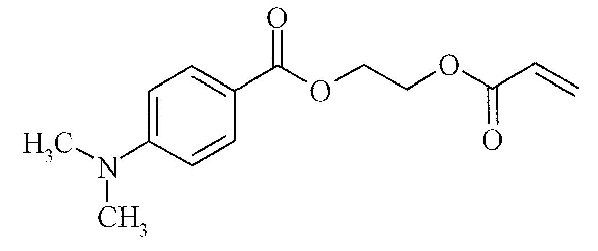
PET100 is a 100 µm unsubbed PET substrate with on the backside an antiblocking layer with antistatic properties available from AGFA-GEVAERT as P100C PLAIN/ABAS. - The curing degree is tested on a coating immediately after curing with UV light. The cured coating is rubbed with the means of a Qtip. When the surface is not damaged, the coating is fully cured. When some of the cured coating can be damaged, the coating is only partly cured. When the whole cured coating is damaged, the coating is not cured.
- The curing speed was defined as the percentage of the maximum output of the lamp needed to cure the samples. The lower the number the higher curing speed. A sample was considered as fully cured at the moment scratching with a Q-tip caused no visual damage.
- A percentage of more then 100 % of the maximum output of the lamp means that the speed of the conveyer belt had to be reduced to get the sample fully cured at the maximum output of the lamp. The higher the percentage, the more the belt had to be slowed down. A curing speed of 160% means a belt speed of 12.5 m/min at the maximum output of the lamp. A percentage between 150% and 200% is considered as at the edge of practical use. A percentage above 200% is considered out of the range for practical use and no higher percentages are measured.
- The viscosity of the formulations was measured using a Brookfield DV-II+ viscometer at 25°C at 3 rotations per minute (RPM) using a CPE 40 spindle. A viscosity of less than 50 mPa.s was regarded to be suitable for inkjet printing.
- This example illustrates the synthesis of polymerizable Norrish Type II photoinitiators according to the present invention.
- The synthesis of 9-oxo-9H-thioxanthen-1-carboxylix acid was optimized starting from the synthesis, disclosed in
US 4367324 (CIBA-GEIGY) .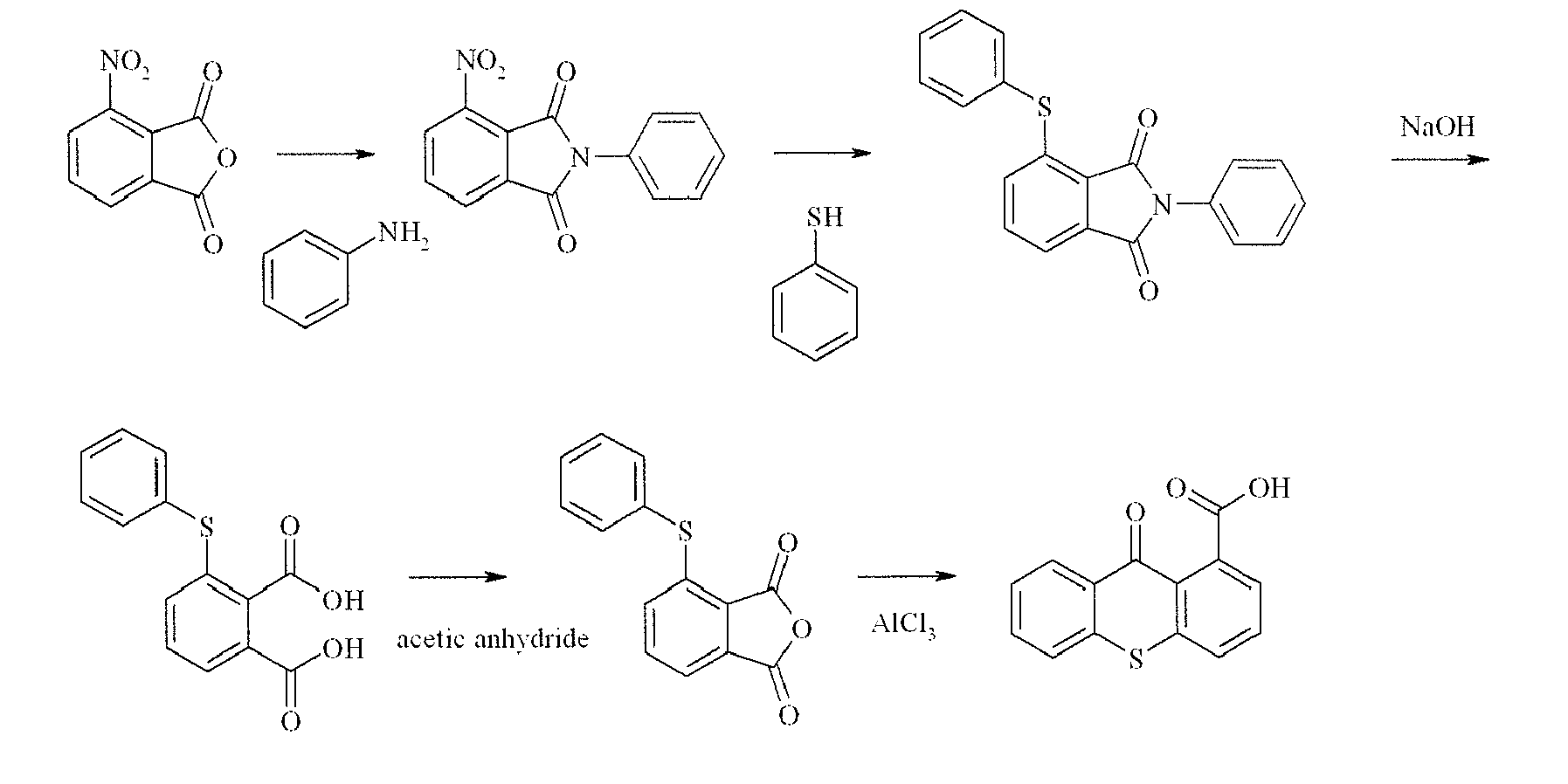
- 50 g (259 mmol) 3-nitro-phtalic anhydride and 24.7 g (24.1 mL, 266 mmol) aniline in 710 mL acetic acid were heated to reflux for 3 hours under an argon atmosphere. Acetic acid was removed under reduced pressure and the residue was treated with 150 mL ethanol at 0°C. The precipitated 3-nitro-phtalanilide was isolated by filtration, washed with a small amount of cold ethanol and dried. 59.1 g (58%) 3-nitro-phtalanilide was isolated (m.p. 139-141 °C).
- 22.2 mL (204 mmol) thiophenol was added to a sodium methanolate solution, freshly prepared from 4.63 g (204 mmol) sodium in 185 mL methanol. The solvent was removed under reduced pressure and the isolated sodium thiophenolate was dissolved in 185 mL DMSO. 49.7 g (185 mmol) 3-nitro-phtalanilide was added and the mixture was heated, while stirring, to 50°C for 90 minutes. The mixture was added carefully to a mixture of 185 mL acetic acid and 185 mL water, while stirring to suppress foaming. The precipitated 3-phenylthio-phtalanilide was isolated by filtration, washed with water at 0°C and dried under reduced pressure at 85°C. 60.5 g (99%) of 3-phenylthio-phtalanilide was isolated (m.p. 150-2°C).
- 34.33 g (103.6 mmol) 3-phenylthio-phtalanilide was suspended in 466 mL of a 20 % sodium hydroxide solution. The mixture was heated for 30 minutes to 105°C (severe foaming!). The mixture was allowed to cool down to room temperature and carefully poured into 239 mL concentrated hydrochloric acid, while cooling. The crude 3-phenylthio-phtalic acid was isolated by filtration, suspended in 330 mL concentrated hydrochloric acid, heated to reflux and allowed to cool down. 3-phenylthio-phtalic acid was isolated by filtration, washed twice with 2 N hydrochloric acid, then twice with a saturated NaCl-solution and dried under reduced pressure at 85°C. 26.7 g (94 %) of 3-phenylthio-phtalic acid was isolated (m.p. 154-8°C).
- 25.6 g (93.5 mmol) 3-phenylthio-phtalic acid and 26.4 mL (281 mmol) acetic anhydride were heated to reflux for 6 hours. The reaction mixture was allowed to cool down to room temperature. Upon standing over night, 3-phenylthio-phtalic anhydride precipitated from the medium. A first crop of 16.8 g of 3-phenylthio-phtalic anhydride was isolated by filtration and dried. The filtrate was evaporated to half of its volume and a second crop of 4.1 g of 3-phenylthio-phtalic anhydride was isolated. 20.9 g (87 %) of 3-phenylthio-phtalic anhydride was isolated (m.p. 148-50°C)
- 17.5 g (68.3 mmol) 3-phenylthio-phtalic anhydride was suspended in 170 mL toluene. 9.64 g (72.8 mmol) AlCl3 was added and the reaction was allowed to continue for 4 hours at room temperature. Toluene was decanted and the residue was treated with water at 0°C. 9-oxo-9H-thioxanthen-1-carboxylic acid precipitated from the medium, was isolated by filtration, washed with water and dried. 15.7 g (90 %) of the crude 9-oxo-9H-thioxanthen-1-carboxylic acid was isolated (m.p. 269-70°C). The carboxylic acid was used without further purification.
-

- 31.08 g (202 mmol) thiosalicylic acid and 50 g (202 mmol) 4-iodo-benzoic acid were added to 410 mL of 10% NaOH. 12.3 g copper powder and 2.04 g zinc powder were added and the mixture was refluxed for 6 hours, while vigorously stirring. The foaming was difficult to control. The reaction mixture was allowed to cool down to room temperature. The copper and zinc powder were removed by filtration. The reaction mixture was diluted with 800 mL water and neutralized with 600 mL 2N HCl. The precipitated diphenylsulfide-2,4'-dicarboxylic acid was isolated by filtration washed three times with water and dried. 55 g of diphenylsulfide-2,4'-dicarboxylic acid was isolated. (m.p. 235-7°C)
9-oxo-9H-thioxanthene-2-carboxylic acid : - 52.74 (192 mmol) diphenylsulfide-2,4'-dicarboxylic acid was dissolved in 1 L concentrated sulfuric acid and the reaction was allowed to continue for 24 hours at room temperature. The reaction mixture was added slowly to 12 L boiling water. The mixture was kept at 100°C for an additional hour. The mixture was allowed to cool down to room temperature. The crude 9-oxo-9H-thioxanthene-2-carboxylic acid precipitated from the mixture, was isolated by filtration, washed three times with water and once with ethanol and dried. 41.76 g of the crude 9-oxo-9H-thioxanthene-2-carboxylic acid was dissolved in 417 mL 2N NaOH, stirred for 30 minutes at room temperature and slowly acidified with 600 ml 2N HCl. The mixture was stirred for 30 minutes and the precipitated 9-oxo-9H-thioxanthene-2-carboxylic acid was isolated by filtration, washed twice with water and twice with ethanol and dried. 31.5 g (64 %) 9-oxo-9H-thioxanthene-2-carboxylic acid was isolated (m.p.: 310-6°C).
- Synthesis of 9-oxo-9H-thioxanthene-1-carboxylic acid-3-(4-acryloyloxy-butoxy)2-hydroxy-propyl ester:

At this temperature 4-hydroxybutylacrylate glycidylether (2.4 g, 12.2 mmol) was added and the mixture was allowed to stir at reflux temperature for 24 hours.
The mixture was cooled to room temperature and filtered to remove the residual, undissolved 9-oxo-9H-thioxanthene-1-carboxylic acid. The filtrate was evaporated under reduced pressure.
The residual oil, which contains dimethylsulfoxide, was brought in distilled water. After stirring for 1 hour the aqueous layer was decanted off. The residue was dissolved in dichloromethane (100 mL) and extracted with a mixture of an aqueous solution of sodium hydroxide (1N) and distilled water (1/2).
The organic layer was separated, dried on MgSO4, filtered and evaporated to provide 4.9 g of a yellow oil.
The product was purified on a SVP D40 Merck Np Column using dichloromethane / ethyl acetate (80/20) as eluent, to afford 2.6 g of a yellow oil. - Synthesis of 9-oxo-9H-thioxanthene-2-carboxylic acid-3-(4-acryloyloxy-butoxy)2-hydroxy-propyl ester:

At this temperature 4-hydroxybutylacrylate glycidylether (1.3 g, 6.34 mmol) was added and the mixture was allowed to stir at reflux temperature for 24 hours.
The mixture was cooled to room temperature and filtered to remove the residual, undissolved 9-oxo-9H-thioxanthene-2-carboxylic acid. The filtrate was evaporated under reduced pressure.
The residual oil was dissolved in methyl-tert-butylether (100 mL) and extracted with a mixture of an aqueous solution of sodium hydroxide (1 N) and distilled water (1/4).
The organic layer was separated, dried on MgSO4, filtered and evaporated to provide 2.5 g of a brown oil. - Synthesis of acrylic acid 4-{2-hydroxy-3-[2-(9-oxo-9H-thioxanthen-2-yloxy)-propionyloxy]propoxy}-butyl ester:

EP 1380580 A (GREAT LAKES).
A reaction mixture containing 2-(9-oxo-9H-thioxanthene-2-yloxy)-propionic acid (4.2 g, 14 mmol), acetonitrile (55 mL), dimethylacetamide (10 mL), tetrabutylammonium bromide (0.5 g, 1.4 mmol)and 2,6-di-tert-butyl-4-methylphenol (0.03 g, 0.114 mmol) was heated to reflux.
At this temperature 4-hydroxybutylacrylate glycidylether (2.3 g, 11.4 mmol) was added and the mixture was allowed to stir at reflux temperature for 16 hours.
The mixture was cooled to room temperature and the solvent was evaporated under reduced pressure.
The residual oil was dissolved in methyl-tert-butylether (100 mL) and extracted with a mixture of an aqueous solution of sodium hydroxide (1 N) and distilled water (1/1).
The organic layer was separated, dried on MgSO4, filtered and evaporated to provide 3.7 g of a yellow oil. - Synthesis of acrylic acid 4-{2-hydroxy-3-[2-(9-oxo-9H-thioxanthen-2-yloxy)-acetoxy]-propoxy}-butyl ester:

EP 1380580 A (GREAT LAKES).
A reaction mixture containing (9-oxo-9H-thioxanthen-2-yloxy) acetic acid (4.0 g, 14 mmol), acetonitrile (55 ml), dimethylacetamide (10 mL), tetrabutylammonium bromide (0.5 g, 1.4 mmol)and 2,6-di-tert-butyl-4-methylphenol (0.03 g, 0.114 mmol) was heated to reflux. At this temperature 4-hydroxybutylacrylate glycidylether (2.3 g, 11.4 mmol) was added and the mixture was allowed to stir at reflux temperature for 16 hours. The mixture was cooled to room temperature and the solvent was evaporated under reduced pressure to provide 8.0 g of a yellow oil. The product was purified on a Prochrom LC80 Column using dichloromethane / ethyl acetate (60/40) as eluent on Kromasil Si60A 10µm, to afford 1.8 g of a yellow oil. - Synthesis of 2-benzoyl-benzoic acid 3-(4-acryloyloxy-butoxy)-2-hydroxypropyl ester:
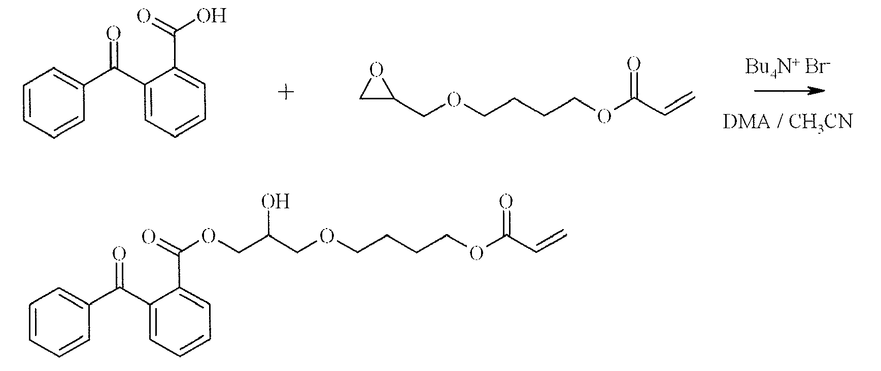
At this temperature 4-hydroxybutylacrylate glycidylether (28.0 g) was added and the mixture was allowed to stir at reflux temperature for 16 hours.
The mixture was cooled to room temperature and the solvent was evaporated under reduced pressure.
The residual oil was dissolved in methyl-tert-butylether (300 mL) and extracted 3 times with a mixture of an aqueous solution of sodium hydroxide (1N) and distilled water (1/2.4)
The organic layer was separated, dried on MgSO4, filtered and evaporated to provide 45.2 g of a brown oil. - Synthesis of Acrylic acid 4-[3-(4-benzoyl-phenoxy)-2-hydroxypropoxy]butyl ester:

- This example illustrates that the polymerizable Norrish Type II photoinitiators according to the present invention have an improved compatability with radiation curable compositions in comparison to two comparative polymerizable Norrish Type II photoinitiators COMPINI-1 and COMPINI-2.
- The comparative initiator COMPINI-1 is 9-oxo-9H-thioxanthen-1-carboxylic acid-(2-acryloyloxyethyl ester).

- The comparative initiator COMPINI-2 is 2-propenoic acid-(9-oxo-9H-thioxanthen-2-yl ester).

- 16 g (103 mmol) thiosalicylic acid was slowly added to 150 mL concentrated sulfuric acid. The mixture is stirred for 5 minutes and 60 g (440 mmol) phenol was added over 30 minutes. The temperature rose to 60°C. The reaction was allowed to continue for 2 hours at 80°C. The reaction was allowed to cool down to room temperature and was added slowly to 3 I boiling water. The mixture was kept at the boiling point for 5 minutes. The mixture was allowed to cool down to room temperature. The precipitated 2-hydroxy-thioxanthen-9-on was isolated by filtration and dried. 14.1 g (63 %) of 2-hydroxy-thioxanthen-9-on was isolated (m.p. 232-241 °C).
2-Propenoic acid-(9-oxo-9H-thioxanthen-2-yl ester): - 30 g (130 mmol) 2-hydroxy-thioxanthen-9-on was suspended in 300 mL acetone. 63.5 g (460 mmol) potassium carbonate and 0.7 g BHT were added. 33 g (260 mmol) 3-chloro-propionylchloride was added over 15 minutes. The mixture was heated to reflux and the reaction was allowed to continue for 3 hours at reflux. The reaction mixture was allowed to cool down to room temperature and the precipitated salts were removed by filtration. The solvent was evaporated under reduced pressure and the crude 2-propenoic acid-(9-oxo-9H-thioxanthen-2-yl ester) was purified by preparative column chromatography on a Prochrom LC80 column, using Kromasil Si 60A 10 µ as silica and methylene chloride as eluent. 15.6 g (43.3 %) of 2-propenoic acid-(9-oxo-9H-thioxanthen-2-yl ester) was isolated.
- The synthesis was performed according to the following scheme :

- 14.2 g (215 mmol) of 85% KOH was dissolved in 100 mL ethanol. The temperature rose to 30°C. 30 g (178 mmol) of 4-dimethylamino benzoic acid was added and the mixture was stirred for 90 minutes. The solvent was evaporated under reduced pressure. The residue was treated with 300 mL methyl tert. butyl ether, isolated by filtration and dried.
- 9.4 g (47 mmol) of 4-dimethylamino benzoic acid potassium salt was added to a solution of 10 g (56 mmol) of 2-bromoethyl acrylate in 40 mL dimethyl acetamide. 1 g of BHT was added and the mixture was heated to 60°C for 2 hours. The reaction was allowed to cool down to room temperature. The formed potassium bromide was removed by filtration and 150 mL of methyl tert. butyl ether was added. The mixture was extracted with 150 mL of water. The organic fraction was isolated, dried over MgSO4 and evaporated under reduced pressure. The residue was redissolved in 150 mL of methyl tert. butyl ether and extracted with 150 mL of a 1 M NaHCO3-solution. The organic layer was dried over MgSO4 and evaporated under reduced pressure. The residue was treated with water. COINI-2 precipitated from the medium, was isolated by filtration and dried. 4.3 g of COINI-2 was isolated.
- The comparative radiation curable compositions COMP-1 and COMP-2 and the inventive radiation curable compositions INV-1 to INV-7 were prepared according to Table 5. The weight% (wt%) was based on the total weight of the radiation curable compositions. Dibutyl phthalate was added to the radiation curable compositions so that it could be used as an internal reference for the analysis of extractable residues.
Table 5 w% of COMP-1 COMP-2 INV-1 INV-2 INV-3 INV-4 INV-5 INV-6 INV-7 VEEA 69.0 69.0 69.0 71.5 69.0 66.5 66.5 66.0 66.0 M600 20.0 20.0 20.0 20.0 20.0 20.0 20.0 20.0 20.0 IC127 2.5 2.5 2.5 2.5 2.5 2.5 2.5 2.5 2.5 COINI-1 5.0 5.0 5.0 - - - - - - COINI-2 - - - 2.5 5.0 5.0 5.0 5.0 5.0 COMPINI-1 2.5 - - - - - - - - COMPINI-2 - 2.5 - - - - - - - TX-1 - - 2.5 2.5 2.5 5.0 - - - TX-2 - - - - - - 5.0 - - TX-7 - - - - - - - 5.5 - TX-5 - - - - - - - - 5.5 Dibutyl phtalate 1.0 1.0 1.0 1.0 1.0 1.0 1.0 1.0 1.0 - 30 mg Tegorad 2100 per 100 g of both the comparative radiation curable compositions COMP-1 and COMP-2 and the inventive radiation curable compositions INV-1 to INV-7 was added.
- The compatibility of both the comparative initiators COMPINI-1 and COMPINI-2 and the inventive initiators TX-1, TX-2, TX-5 and TX-7 was evaluated. The solubility results are summarized in Table 6.
Table 6 Radiation curable composition Thioxanthone solubility COMP-1 insoluble at room temperature, soluble at 70°C COMP-2 insoluble, even at 70°C INV-1 soluble at room temperature INV-2 soluble at room temperature INV-3 soluble at room temperature INV-4 soluble at room temperature INV-5 soluble at room temperature INV-6 soluble at room temperature INV-7 soluble at room temperature - From Table 6, it should be clear that only the initiators according to the present invention have a good compatibility over a sufficient wide range of concentrations to be applicable in a broad scope of radiation curable formulations.
- The curing speed of the inventive radiation curable compositions INV-1 to INV-7 was evaluated. The inventive radiation curable compositions INV-1 to INV-7 were coated on a PET100 substrate using a bar coater and a 10µm wired bar. The coatings were cured using a Fusion DRSE-120 conveyer, equipped with a Fusion VPS/1600 lamp (D-bulb), which transported the samples under the UV-lamp on a conveyer belt at a speed of 20 m/min. The curing speed was defined as the percentage of the maximum output of the lamp needed to cure the samples.
- The viscosity of the formulations was measured using a Brookfield DV-II+ viscometer.
- The results are summarized in Table 7(*: measured at 45°C at 12 rotations per minute).
Table 7 Radiation curable compositions Viscosity (mPas) Curing speed (% of the maximum output) INV-1 5.4 * 80 INV-2 4.8 * 80 INV-3 5.1 * 75 INV-4 11.8 (5.4 *) 65 INV-5 10.1 60 INV-6 9.9 65 INV-7 13.2 60 - From Table 7, it becomes clear that radiation curable compositions according to the present invention all exhibit high curing speeds under ambient atmosphere and are well within the viscosity range for jettable formulations.
- Coated samples of the radiation curable compositions INV-4 to INV-7 were prepared to determine extractable residues as described below.
- The free radical curable liquids INV-4 to INV-7 were coated on a PET100 substrate using a bar coater and a 10 µm wired bar. Each coated sample was cured using a Fusion DRSE-120 conveyer, equipped with a Fusion VPS/I600 lamp (D-bulb), which transported the samples under the UV-lamp on a conveyer belt at a speed of 20 m/min. The lamp was used at its maximum output.
- Two samples of 7.068 cm2 of INV-4 to INV-7 were put into a 50 ml beaker and extracted with 4.5 ml acetonitrile, using ultrasound for 30 minutes at room temperature. The extract was transferred into a 5 ml volumetric flask. The samples were rinsed twice with a small amount of acetonitrile and the rinsing solvent was transferred into the 5 ml volumetric flask until the volume was adjusted to 5 ml. The solution was thoroughly mixed and filtered over a 0.45 µm filter. 15 µl of each sample was injected on the HPLC.
- An Alltima C18 5 µm column (150 x 3.2 mm), supplied by Alltech, was used. A flow rate of 0.5 ml/min was used at a temperature of 40°C. A DAD detector at 258 nm and 312 nm was used to detect the extracted initiator.
- The following HPLC-method was used for all samples.
- Eluent A : H2O + 0.02M KH2PO4 pH = 2.5 using H3PO4
- Eluent B : H2O + 0.02M KH2PO4 pH = 2.5 using H3PO4/ CH3CN [40/60] (v/v)
- Eluent C : H2O/CH3CN [40/60] (v/v)
- Eluent D : H2O/CH3CN [10/90] (v/v)
- The gradient (end run = 38 min) is shown by Table 8.
Table 8 Time (min) % eluent A % eluent B %eluent C % eluent D 0 70 30 0 0 6 70 30 0 0 11 0 100 0 0 20 0 100 0 0 21 0 0 100 0 24 0 0 100 0 25 0 0 0 100 30 0 0 0 100 31 70 30 0 0 38 70 30 0 0 - The concentration was determined in comparison with a reference sample of a known concentration of each inventive initiator, eluted under the same conditions as the extracted samples. A total coating weight 10 g/m2 was assumed for each sample.
- The results are summarized in Table 9.
Table 9 Radiation curable composition Extractable residues (mg/m2) % of the initiator which remains extractable INV-4 1.2 0.25 INV-5 0.7 0.15 INV-6 0.4 0.05 INV-7 0.4 0.05 - This example illustrates the performance of the Norrish Type II photoinitiators according to the present invention in combination with a polymerizable co-initiator and a polymerizable Norrish Type I photoinitiator.
- The inventive radiation curable compositions INV-8 to INV-11 were prepared according to Table 10.The weight% (wt%) was based on the total weight of the radiation curable compositions.Dibutyl phthalate was added to the radiation curable compositions so that it could be used as an internal reference for the analysis of extractable residues.
Table 10 wt% of INV-8 INV-9 INV-10 INV-11 VEEA 66.5 64.0 61.5 59.0 M600 20.0 20.0 20.0 20.0 Type I 2.5 5.0 7.5 7.5 COINI-2 5.0 5.0 5.0 7.5 TX-1 5.0 5.0 5.0 5.0 dibutyl phtalate 1.0 1.0 1.0 1.0 - The curing speed of the inventive radiation curable compositions INV-8 to INV-11 was evaluated. The inventive radiation curable compositions INV-8 to INV-11 were coated on a PET100 substrate using a bar coater and a 10 µm wired bar. The coatings were cured using a Fusion DRSE-120 conveyer, equipped with a Fusion VPS/I600 lamp (D-bulb), which transported the samples under the UV-lamp on a conveyer belt at a speed of 20 m/min. The curing speed was defined as the percentage of the maximum output of the lamp needed to cure the samples.
- The viscosity of the formulations was measured using a Brookfield DV-II+ viscometer.
- The results are summarized in Table 11.
Table 11 Radiation curable compositions Viscosity (mPas) Curing speed (% of the maximum output) INV-8 11.1 90 INV-9 11.3 75 INV-10 12.2 60 INV-11 16.4 50 - All radiation curable compositions according to the present invention show a good to excellent curing speed under ambient atmosphere and are well within the viscosity range for jettable formulations.
- Coated samples of radiation curable compositions INV-8 to INV-11 were prepared to determine extractable residues as described below.
- The free radical curable liquids INV-8 to INV-11 were coated on a PET100 substrate using a bar coater and a 10 µm wired bar. Each coated sample was cured using a Fusion DRSE-120 conveyer, equipped with a Fusion VPS/I600 lamp (D-bulb), which transported the samples under the UV-lamp on a conveyer belt at a speed of 20 m/min. The lamp was used at its maximum output.
- Two samples of 7.068 cm2 of INV-8 to INV-11 were put into a 50 ml beaker and extracted with 4.5 ml acetonitrile, using ultrasound for 30 minutes at room temperature. The extract was transferred into a 5 ml volumetric flask. The samples were rinsed twice with a small amount of acetonitrile and the rinsing solvent was transferred into the 5 ml volumetric flask until the volume was adjusted to 5 ml. The solution was thoroughly mixed and filtered over a 0.45 µm filter. 15 µl of each sample was injected on the HPLC.
- An Alltima C18 5µm column (150 x 3.2 mm), supplied by Alltech, was used. A flow rate of 0.5 ml/min was used at a temperature of 40°C. A DAD detector at 291 nm was used to detect the extracted initiators and the coinitiator.
- The following HPLC-method was used for all samples.
- Eluent A : H2O + 0.02M KH2PO4 pH = 2.5 using H3PO4
- Eluent B : H2O + 0.02M KH2PO4 pH = 2.5 using H3PO4/ CH3CN [40/60] (v/v)
- Eluent C : H2O/CH3CN [40/60] (v/v)
- Eluent D : H2O/CH3CN [10/90] (v/v)
- The gradient (end run = 38 min) is shown by Table 12.
Table 12 Time (min) % eluent A % eluent B %eluent C % eluent D 0 70 30 0 0 6 70 30 0 0 11 0 100 0 0 20 0 100 0 0 21 0 0 100 0 24 0 0 100 0 25 0 0 0 100 30 0 0 0 100 31 70 30 0 0 38 70 30 0 0 - The concentration was determined in comparison with a reference sample of a known concentration of each initiator and co-initiator, eluted under the same conditions as the extracted samples. A total coating weight 10 g/m2 was assumed for each sample. The results are summarized in Table 13.
Table 13 Radiation curable composition Extractable amount of : (expressed as % which remains extractable) TX-1 Type I COINI-2 INV-8 1.3 1.2 0.4 INV-9 0.9 0.9 0.3 INV-10 0.8 0.9 0.3 INV-11 0.9 1.5 0.6 - From Table 13, it becomes clear that only minor fractions of both the initiators and the co-initiator remain extractable.
Claims (15)
- A polymerizable Norrish Type II photoinitiator according to Formula (I):

A represents a Norrish type II initiator selected from the group consisting of a optionally substituted benzophenone and an optionally substituted thioxanthone;
L1 represents a divalent linking group, positioning the Norrish type II initiator moiety A and the C=O-group in a 1 to X position, where position 1 is defined as the atom in the aromatic ring of A to which L1 is covalently bonded and position X is defined as the carbon atom of the C=O-group;
n represents 0 or 1;
m represents 0 or 1, with the proviso that n is equal to 0, when m is equal to 0; X represents an integer selected from 3 to 7;
R1 is selected from the group consisting of a hydrogen, an optionally substituted alkyl group, an optionally substituted alkenyl group, an optionally substituted alkynyl group, an optionally substituted alkaryl group, an optionally substituted aralkyl group, an optionally substituted aryl group, an optionally substituted heteroaryl group and an acyl group;
R2 represents hydrogen or a methyl group;
L2 represents a divalent linking group, selected from the group consisting of an optionally substituted saturated alkylene group, an optionally substituted unsaturated alkylene group, an optionally substituted arylene group and a group represented by Formula (II) :
R3 to R6 independently represent hydrogen or a methyl group; and
p represents an integer from 1 to 10. - The polymerizable Norrish Type II photoinitiator according to claim 1 wherein the integer n is 0.
- The polymerizable Norrish Type II photoinitiator according to claim 1 or 2 wherein L2 represents an optionally substituted saturated alkylene group.
- The polymerizable Norrish Type II photoinitiator according to any one of claims 1 to 3 wherein the group R2 represents hydrogen.
- The polymerizable Norrish Type II photoinitiator selected from the group consisting of


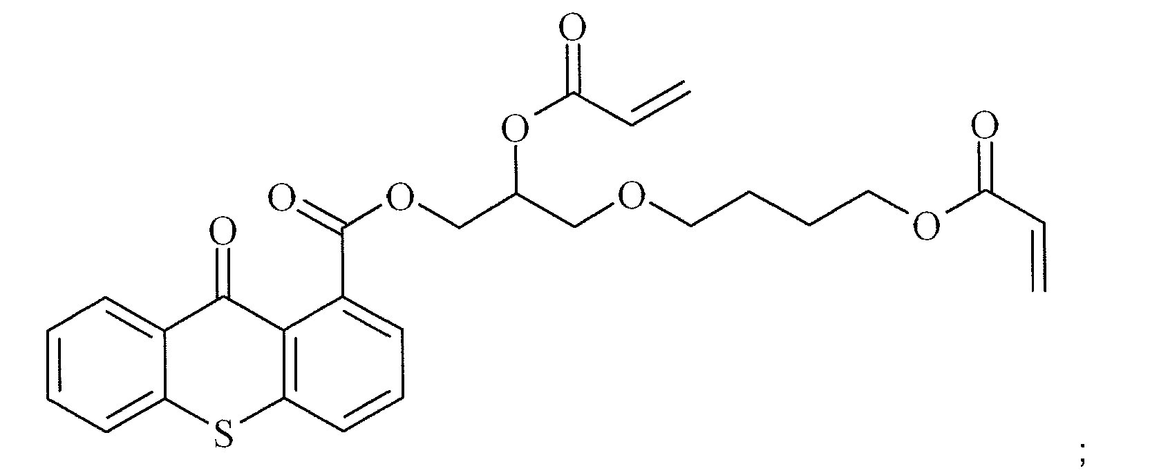

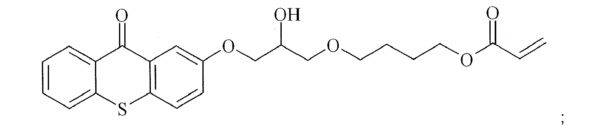


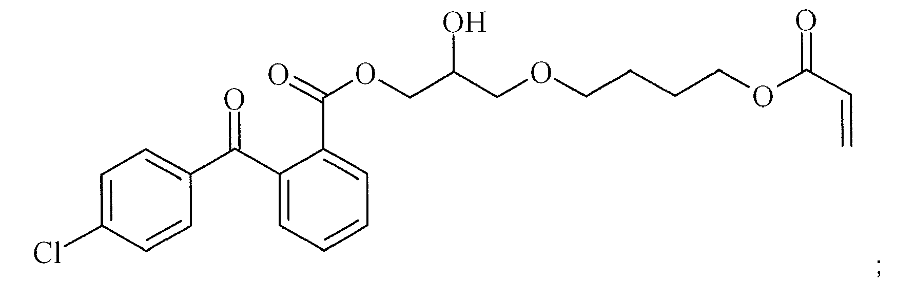


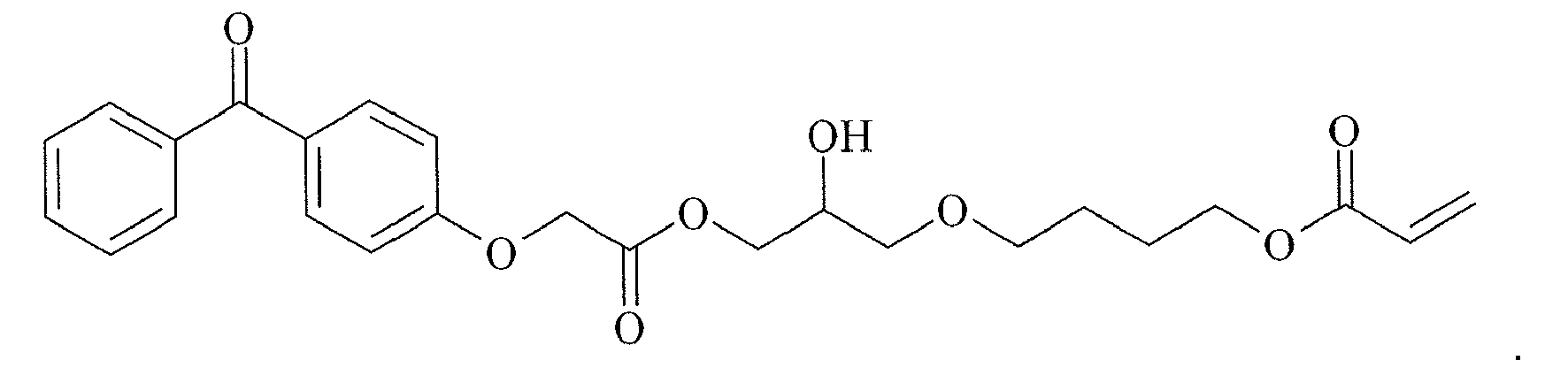
- A radiation curable composition including a polymerizable Norrish Type II-photoinitiator as defined by any on of claims 1 to 5 and at least one co-initiator.
- The radiation curable composition according to claim 6 wherein the co-initiator is a diffusion hindered dialkylamino substituted aromatic compound selected from the group consisting of a polymeric dialkylamino substituted aromatic compound, a multifunctional dialkylamino substituted aromatic compound and a dialkylamino substituted aromatic compound comprising at least one ethylenically unsaturated polymerizable group.
- The radiation curable composition according to claim 7 wherein the diffusion hindered dialkylamino substituted aromatic compound includes one ethylenically unsaturated polymerizable group.
- The radiation curable composition according to claim 7 or 8 wherein the diffusion hindered dialkylamino substituted aromatic compound is a 4-dialkylamino-benzoic acid derivative.
- The radiation curable composition according to any one of claims 7 to 9, wherein the composition comprises a colorant.
- A radiation curable inkjet ink including the radiation curable composition according to any one of claims 7 to 10.
- An inkjet printing method comprising the steps of:a) providing a radiation curable composition according to any one of claims 7 to 11; andb) at least partially curing the radiation curable composition.
- The inkjet printing method according to claim 12 wherein the radiation curable composition is applied to a substrate by flexographic printing and an inkjet ink is printed upon the at least partially cured radiation curable composition.
- The inkjet printing method according to claim 12 wherein the radiation curable composition is jetted upon a substrate.
- Use of a polymerizable Norrish Type II photoinitiator according to any one of claims 1 to 5 to reduce the amount of extractable photoinitiator from a cured layer of a radiation curable composition.
Priority Applications (6)
| Application Number | Priority Date | Filing Date | Title |
|---|---|---|---|
| EP08105272.2A EP2161264B1 (en) | 2008-09-09 | 2008-09-09 | Polymerizable photoinitiators and radiation curable compositions |
| CN200980135819.6A CN102149704B (en) | 2008-09-09 | 2009-09-04 | Polymerizable photoinitiators and radiation curable compositions |
| PCT/EP2009/061444 WO2010029017A1 (en) | 2008-09-09 | 2009-09-04 | Polymerizable photoinitiators and radiation curable compositions |
| JP2011525555A JP5722777B2 (en) | 2008-09-09 | 2009-09-04 | Polymerizable photoinitiator and radiation curable composition |
| US13/060,278 US8530510B2 (en) | 2008-09-09 | 2009-09-04 | Polymerizable photoinitiators and radiation curable compositions |
| BRPI0918529-1A BRPI0918529A2 (en) | 2008-09-09 | 2009-09-04 | Polymerizable norrish type ii photoinitiator, radiation curable composition, inkjet printing method and use of photoinitiator |
Applications Claiming Priority (1)
| Application Number | Priority Date | Filing Date | Title |
|---|---|---|---|
| EP08105272.2A EP2161264B1 (en) | 2008-09-09 | 2008-09-09 | Polymerizable photoinitiators and radiation curable compositions |
Publications (2)
| Publication Number | Publication Date |
|---|---|
| EP2161264A1 true EP2161264A1 (en) | 2010-03-10 |
| EP2161264B1 EP2161264B1 (en) | 2019-11-27 |
Family
ID=40785507
Family Applications (1)
| Application Number | Title | Priority Date | Filing Date |
|---|---|---|---|
| EP08105272.2A Active EP2161264B1 (en) | 2008-09-09 | 2008-09-09 | Polymerizable photoinitiators and radiation curable compositions |
Country Status (6)
| Country | Link |
|---|---|
| US (1) | US8530510B2 (en) |
| EP (1) | EP2161264B1 (en) |
| JP (1) | JP5722777B2 (en) |
| CN (1) | CN102149704B (en) |
| BR (1) | BRPI0918529A2 (en) |
| WO (1) | WO2010029017A1 (en) |
Cited By (65)
| Publication number | Priority date | Publication date | Assignee | Title |
|---|---|---|---|---|
| EP2399966A1 (en) | 2010-06-24 | 2011-12-28 | Agfa-Gevaert | Flexible, Scratch Resistant Radiation Curable Inkjets Inks |
| EP2399965A1 (en) | 2010-06-24 | 2011-12-28 | Agfa-Gevaert | Flexible, Scratch Resistant Radiation Curable Inkjet Inks |
| EP2444429A1 (en) | 2010-10-20 | 2012-04-25 | Agfa-Gevaert | Led curable compositions |
| WO2012052288A1 (en) | 2010-10-20 | 2012-04-26 | Agfa-Gevaert | Polymerisable photoinitiators for led curable compositions |
| WO2012084811A1 (en) | 2010-12-20 | 2012-06-28 | Agfa Graphics Nv | A curable jettable fluid for making a flexographic printing master |
| WO2012102046A1 (en) | 2011-01-26 | 2012-08-02 | コニカミノルタホールディングス株式会社 | Active-energy-ray-curable inkjet ink composition, active-energy-ray-curable inkjet ink, and inkjet recording method |
| EP2500387A1 (en) * | 2011-03-15 | 2012-09-19 | Fujifilm Corporation | Ink composition, image forming method, and print material |
| EP2599841A1 (en) | 2011-12-02 | 2013-06-05 | Agfa Graphics N.V. | White inkjet inks |
| WO2013084511A1 (en) | 2011-12-08 | 2013-06-13 | コニカミノルタ株式会社 | Photocuring inkjet ink and image forming method using same |
| WO2013113572A1 (en) | 2012-01-31 | 2013-08-08 | Agfa-Gevaert | Radiation curable etch resistant inkjet ink printing |
| EP2671722A1 (en) | 2012-06-06 | 2013-12-11 | Agfa Graphics N.V. | Radiation curable inkjet inks and industrial inkjet printing methods |
| EP2682273A1 (en) | 2012-07-06 | 2014-01-08 | Agfa Graphics Nv | Methods for inkjet varnishing |
| EP2684922A1 (en) | 2012-07-10 | 2014-01-15 | Agfa Graphics N.V. | Radiation curable fluids |
| EP2684876A1 (en) | 2012-07-10 | 2014-01-15 | Agfa Graphics N.V. | Polymerizable thioxanthones |
| EP2703457A1 (en) | 2012-08-31 | 2014-03-05 | Agfa Graphics N.V. | Low migration free radical radiation curable inkjet inks |
| EP2703180A1 (en) | 2012-08-27 | 2014-03-05 | Agfa Graphics Nv | Free radical radiation curable liquids for de-inking substrates |
| EP2703455A1 (en) | 2012-09-03 | 2014-03-05 | Agfa Graphics Nv | Inkjet inks comprising inorganic pigments |
| WO2014032936A1 (en) | 2012-08-27 | 2014-03-06 | Agfa Graphics Nv | Recycling of radiation cured printed matter |
| EP2725075A1 (en) | 2012-10-24 | 2014-04-30 | Agfa-Gevaert | Radiation curable inkjet inks |
| WO2014206673A1 (en) | 2013-06-24 | 2014-12-31 | Agfa Graphics Nv | White inkjet ink printing |
| WO2015031927A1 (en) * | 2013-09-06 | 2015-03-12 | Durst Phototechnik Digital Technology Gmbh | Photoinitiator |
| EP2848659A1 (en) | 2013-09-16 | 2015-03-18 | Agfa Graphics Nv | Radiation curable compositions for food packaging |
| EP2868721A1 (en) | 2013-10-29 | 2015-05-06 | Agfa Graphics N.V. | Radiation curable brown inkjet ink |
| EP2942203A1 (en) | 2014-05-06 | 2015-11-11 | Agfa Graphics Nv | Inkjet printing outdoor graphics |
| EP2942204A1 (en) | 2014-05-06 | 2015-11-11 | Agfa Graphics Nv | Inkjet printing outdoor graphics |
| EP2960306A1 (en) | 2014-06-26 | 2015-12-30 | Agfa Graphics Nv | Aqueous radiation curable inkjet inks |
| US9309341B2 (en) | 2010-12-20 | 2016-04-12 | Agfa Graphics Nv | Curable jettable fluid for making a flexographic printing master |
| EP3017960A1 (en) | 2014-11-05 | 2016-05-11 | Agfa Graphics Nv | Inkjet printing of pearlescent and metallic colours |
| EP3034312A1 (en) | 2014-12-18 | 2016-06-22 | Agfa Graphics Nv | Radiation curable compositions for printing on glass |
| EP3034311A1 (en) | 2014-12-18 | 2016-06-22 | Agfa Graphics Nv | Inkjet printing of pearlescent and metallic colours |
| WO2016096652A1 (en) | 2014-12-18 | 2016-06-23 | Agfa Graphics Nv | Laminated glass articles |
| EP3070130A1 (en) | 2015-03-20 | 2016-09-21 | Agfa Graphics Nv | Uv curable colourless inkjet liquids |
| EP3081288A1 (en) | 2015-04-15 | 2016-10-19 | Agfa Graphics Nv | Self-dispersing capsules |
| EP3081607A1 (en) | 2015-04-15 | 2016-10-19 | Agfa Graphics Nv | Aqueous resin based inkjet inks |
| EP3095614A1 (en) | 2015-05-22 | 2016-11-23 | Agfa Graphics Nv | Manufacturing of decorative surfaces by inkjet |
| EP3119170A1 (en) | 2015-07-14 | 2017-01-18 | Agfa-Gevaert | Manufacturing printed circuit boards using uv free radical curable inkjet inks |
| EP3156463A1 (en) | 2015-10-13 | 2017-04-19 | Agfa Graphics Nv | Uv curable inkjet inks |
| EP3156461A1 (en) | 2015-10-13 | 2017-04-19 | Agfa Graphics Nv | Uv curable inkjet inks |
| EP3156462A1 (en) | 2015-10-13 | 2017-04-19 | Agfa Graphics Nv | Uv curable inkjet inks |
| EP3173246A1 (en) | 2015-11-30 | 2017-05-31 | Agfa Graphics NV | Inkjet ink set for a method of manufacturing a packaging |
| EP3222684A1 (en) | 2016-03-21 | 2017-09-27 | Agfa Graphics NV | Uv curable inkjet inks |
| EP3241874A1 (en) | 2016-05-04 | 2017-11-08 | Agfa Graphics NV | Acylphosphine oxide photoinitiators |
| WO2017211587A1 (en) | 2016-06-07 | 2017-12-14 | Agfa Graphics Nv | Photoinitiators and curable compositions |
| EP3260505A1 (en) | 2016-06-22 | 2017-12-27 | Agfa Nv | Methods of manufacturing packaging for food, cosmetics and pharma |
| WO2017220425A1 (en) | 2016-06-23 | 2017-12-28 | Agfa Nv | Polymerizable photoinitiators |
| EP3300916A1 (en) | 2016-09-30 | 2018-04-04 | Agfa Nv | Manufacturing of decorative surfaces |
| EP3300915A1 (en) | 2016-09-30 | 2018-04-04 | Agfa Nv | Inkjet printing methods for decorative surfaces |
| US10071353B2 (en) | 2015-01-29 | 2018-09-11 | Hewlett-Packard Development Company, L.P. | Aqueous dispersant formulation |
| WO2019063585A1 (en) * | 2017-09-29 | 2019-04-04 | Merck Patent Gmbh | Polymerisable compounds and the use thereof in liquid-crystal displays |
| WO2019081339A1 (en) | 2017-10-27 | 2019-05-02 | Agfa Nv | Free radical uv curable inkjet ink sets and inkjet printing methods |
| WO2019106089A1 (en) | 2017-12-01 | 2019-06-06 | Agfa Nv | Radiation curable polyurethane resin for ink jet ink |
| WO2019243039A1 (en) | 2018-06-19 | 2019-12-26 | Agfa Nv | Acylphosphineoxide initiators |
| EP3686251A1 (en) | 2019-01-24 | 2020-07-29 | Agfa Nv | Radiation curable inkjet inks for interior decoration |
| WO2020152037A1 (en) | 2019-01-24 | 2020-07-30 | Agfa Nv | Radiation curable inkjet inks for interior decoration |
| WO2020225014A1 (en) | 2019-05-06 | 2020-11-12 | Agfa Nv | Aqueous inkjet ink comprising a resin |
| WO2022128258A1 (en) | 2020-12-16 | 2022-06-23 | Agfa Nv | Uv curable inkjet inks and inkjet printing methods |
| EP4050073A1 (en) | 2021-02-26 | 2022-08-31 | Agfa Nv | Ink set and inkjet printing methods |
| EP4050072A1 (en) | 2021-02-26 | 2022-08-31 | Agfa Nv | Manufacturing methods of decorative surfaces |
| WO2022253753A1 (en) | 2021-06-01 | 2022-12-08 | Agfa Nv | Uv led free radical curable inkjet inks |
| EP4159820A1 (en) | 2021-10-04 | 2023-04-05 | Agfa Nv | Free radical curable inkjet inks |
| EP4227373A1 (en) | 2022-02-10 | 2023-08-16 | Agfa Nv | Free radical curable inkjet inks and inkjet printing methods |
| EP4339248A1 (en) | 2022-09-19 | 2024-03-20 | Agfa Nv | Pigmented free radical curable inkjet inks |
| EP4410907A1 (en) | 2023-01-31 | 2024-08-07 | Agfa Nv | Decorated natural leather |
| EP4603516A1 (en) * | 2024-01-18 | 2025-08-20 | Covestro (Taiwan) Ltd | Photoinitiator and curable composition comprising the same |
| EP4617331A1 (en) | 2024-03-15 | 2025-09-17 | Agfa Nv | Uv curable inkjet inks and inkjet printing methods |
Families Citing this family (37)
| Publication number | Priority date | Publication date | Assignee | Title |
|---|---|---|---|---|
| GB201005060D0 (en) | 2010-03-25 | 2010-05-12 | Davidson Robert S | Synergists |
| US9056986B2 (en) | 2010-11-09 | 2015-06-16 | Seiko Epson Corporation | Ultraviolet curable type ink-jet ink composition, recording method and recording apparatus using same |
| JP5810795B2 (en) * | 2010-11-22 | 2015-11-11 | セイコーエプソン株式会社 | UV curable ink composition for inkjet |
| JP5398760B2 (en) | 2011-02-23 | 2014-01-29 | 富士フイルム株式会社 | Ink composition, image forming method and printed matter |
| EP2543707B2 (en) | 2011-07-08 | 2020-09-02 | Seiko Epson Corporation | Photocurable ink composition for ink jet recording and ink jet recording method |
| US20140275319A1 (en) * | 2011-10-27 | 2014-09-18 | Dic Corporation | Active-energy-radiation-curable inkjet recording ink |
| EP2617783A1 (en) * | 2012-01-20 | 2013-07-24 | Cytec Surface Specialties, S.A. | Photo-reactive Binder |
| EP2617705A1 (en) * | 2012-01-20 | 2013-07-24 | Cytec Surface Specialties, S.A. | Amino Photo-Reactive Binder |
| CN103358742B (en) | 2012-03-28 | 2017-07-04 | 精工爱普生株式会社 | Inkjet recording method, ultraviolet curable ink, inkjet recording device |
| JP6191120B2 (en) | 2012-03-29 | 2017-09-06 | セイコーエプソン株式会社 | Ink jet recording method and ink jet recording apparatus |
| US10029483B2 (en) | 2012-04-25 | 2018-07-24 | Seiko Epson Corporation | Ink jet recording method, ultraviolet-ray curable ink, and ink jet recording apparatus |
| JP6236768B2 (en) | 2012-04-27 | 2017-11-29 | セイコーエプソン株式会社 | Ink jet recording method and ink jet recording apparatus |
| JP6065535B2 (en) | 2012-11-15 | 2017-01-25 | セイコーエプソン株式会社 | UV-curable ink composition for ink jet recording, ink container, and ink jet recording apparatus |
| JP6230300B2 (en) * | 2013-06-28 | 2017-11-15 | 太陽インキ製造株式会社 | Photocurable composition and cured product thereof |
| US10189930B2 (en) | 2013-07-23 | 2019-01-29 | Allnex Belgium S.A. | Polymeric photoinitiators |
| US9884973B2 (en) | 2013-10-23 | 2018-02-06 | Toyo Ink Sc Holdings Co., Ltd. | Active energy ray-curable inkjet ink and ink set |
| CN105683225B (en) * | 2013-12-05 | 2019-09-03 | 积水化学工业株式会社 | Sealant for liquid crystal display element, upper and lower conduction material, and liquid crystal display element |
| US10000649B2 (en) | 2014-03-14 | 2018-06-19 | Toyo Ink Sc Holdings Co., Ltd. | Active energy ray-curable inkjet ink composition |
| JP6454217B2 (en) * | 2014-05-13 | 2019-01-16 | 積水化学工業株式会社 | Modified dialkylaminobenzoic acid-based compound, modified thioxanthone derivative, photocurable resin composition, liquid crystal display element sealing agent, vertical conduction material, and liquid crystal display element |
| CN104262511B (en) * | 2014-09-02 | 2016-11-23 | 天津久日新材料股份有限公司 | Polymerizable coinitiator and UV curable compositions |
| CN104277283B (en) * | 2014-09-05 | 2017-10-10 | 广州大禹防漏技术开发有限公司 | A kind of TPO waterproof membrane of ultraviolet light cross-linking and preparation method thereof |
| US10400066B2 (en) * | 2015-01-27 | 2019-09-03 | Hewlett-Packard Development Company, L.P. | Polymeric photoactive agents |
| WO2016122452A1 (en) * | 2015-01-27 | 2016-08-04 | Hewlett-Packard Development Company, L.P. | Polymeric amine synergists |
| WO2016122454A1 (en) | 2015-01-27 | 2016-08-04 | Hewlett-Packard Development Company, L.P. | Polymeric photo active agents |
| WO2016153035A1 (en) * | 2015-03-26 | 2016-09-29 | コニカミノルタ株式会社 | Actinic radiation-curable inkjet ink and inkjet printing method |
| US10414862B2 (en) * | 2015-07-09 | 2019-09-17 | Hewlett-Packard Development Company, L.P. | Polymeric amine synergist |
| WO2017074394A1 (en) * | 2015-10-29 | 2017-05-04 | Hewlett-Packard Development Company, L.P. | Photo curable ink composition |
| JP6256548B2 (en) * | 2016-08-18 | 2018-01-10 | セイコーエプソン株式会社 | UV curable ink composition |
| CN115960312B (en) * | 2018-08-16 | 2023-11-03 | 江苏百赛飞生物科技有限公司 | Polymerizable photosensitive monomer, photosensitive polymer based on polymerizable photosensitive monomer and biomaterial surface modification method |
| GB201915023D0 (en) * | 2019-10-17 | 2019-12-04 | Lambson Ltd | Amine co-initiator mixture |
| JP7615559B2 (en) * | 2020-08-04 | 2025-01-17 | Dic株式会社 | Energy ray curable inkjet printing ink and method for producing printed matter |
| FR3118965B1 (en) * | 2021-01-20 | 2023-12-01 | Arkema France | POLYMERIZABLE THIOXANTHONE |
| AR126088A1 (en) * | 2021-06-08 | 2023-09-13 | Sicpa Holding Sa | UV-LED RADIATION CURABLE HYBRID PROTECTIVE VARNISHES FOR SECURITY DOCUMENTS |
| CN115701428B (en) * | 2021-08-02 | 2024-05-03 | 上海发微医用材料有限公司 | Photoinitiator and application thereof |
| JPWO2023120275A1 (en) * | 2021-12-20 | 2023-06-29 | ||
| EP4249518B1 (en) * | 2022-03-25 | 2024-11-06 | Arkema France | Polymerizable photoinitiators |
| CN114805296B (en) * | 2022-05-10 | 2024-07-19 | 艾坚蒙(安庆)科技发展有限公司 | Thioxanthone derivative, preparation method and application thereof |
Citations (18)
| Publication number | Priority date | Publication date | Assignee | Title |
|---|---|---|---|---|
| NL6409466A (en) * | 1962-06-18 | 1966-02-18 | ||
| US4367324A (en) | 1980-02-05 | 1983-01-04 | Ciba-Geigy Corporation | Photocrosslinkable polymers with thioxanthone and imidyl groupings in side chains |
| US4390676A (en) * | 1976-11-15 | 1983-06-28 | Schering Corporation | Ultraviolet absorbing lenses |
| EP0377191A2 (en) * | 1988-12-31 | 1990-07-11 | BASF Aktiengesellschaft | Radiation-sensitive ethylenically unsaturated copolymerisable compounds, and process for their preparation |
| US6310115B1 (en) | 1998-10-29 | 2001-10-30 | Agfa-Gevaert | Ink compositions for ink jet printing |
| WO2003033492A1 (en) | 2001-10-18 | 2003-04-24 | Coates Brothers Plc | Multi-functional thioxanthone photoinitiators |
| JP2003268048A (en) * | 2002-03-15 | 2003-09-25 | Nippon Shokubai Co Ltd | Resin composition for forming ultraviolet shielding layer and ultraviolet shielding laminate |
| EP1380580A1 (en) | 2002-07-13 | 2004-01-14 | Great Lakes (UK) Limited | An improved process for the production of subsituted thioxanthones |
| JP2004224993A (en) | 2003-01-27 | 2004-08-12 | Nippon Kayaku Co Ltd | Self-polymerization type photopolymerization initiator and photosensitive resin composition by using the same |
| CN1727320A (en) * | 2005-02-03 | 2006-02-01 | 常州华钛化学有限公司 | reactive benzophenone photoinitiator and preparation method thereof |
| EP1674499A1 (en) | 2004-12-21 | 2006-06-28 | Agfa-Gevaert | Radiation curable compositions |
| EP1790698A1 (en) | 2005-11-28 | 2007-05-30 | Agfa Graphics N.V. | Non-aqueous diketopyrrolo-pyrrole pigment dispersions using dispersion synergists |
| EP1790695A1 (en) | 2005-11-28 | 2007-05-30 | Agfa Graphics N.V. | Non-aqueous quinacridone dispersions using dispersion synergists |
| EP1790696A1 (en) | 2005-11-28 | 2007-05-30 | Agfa Graphics N.V. | Non-aqueous pigment dispersions containing specific dispersion synergists |
| EP1790697A1 (en) | 2005-11-28 | 2007-05-30 | Agfa Graphics N.V. | Non-aqueous pigment dispersions containing specific dispersion synergists |
| EP1911814A1 (en) | 2006-10-11 | 2008-04-16 | Agfa Graphics N.V. | Methods for preparing curable pigment inkjet ink sets |
| JP2008133486A (en) * | 2008-02-18 | 2008-06-12 | Nippon Shokubai Co Ltd | Resin composition for forming ultraviolet shielding layer and ultraviolet shielding laminate |
| WO2008074548A1 (en) | 2006-12-21 | 2008-06-26 | Agfa Graphics Nv | White inkjet ink improved for dispersion stability |
Family Cites Families (6)
| Publication number | Priority date | Publication date | Assignee | Title |
|---|---|---|---|---|
| JPS5495688A (en) * | 1978-01-13 | 1979-07-28 | Fuji Photo Film Co Ltd | Photopolymerizable composition |
| JP3632232B2 (en) * | 1994-02-21 | 2005-03-23 | 東レ株式会社 | Photosensitive resin plate material |
| BRPI0413348A (en) * | 2003-08-04 | 2006-10-10 | Ciba Sc Holding Ag | process for producing strongly adherent coatings |
| EP1616921B1 (en) * | 2004-07-15 | 2007-10-31 | Agfa Graphics N.V. | Novel radiation curable compositions |
| ATE431246T1 (en) * | 2004-09-16 | 2009-05-15 | Agfa Graphics Nv | METHOD FOR PRODUCING A FLEXO PRINTING PLATE |
| EP1940981A1 (en) * | 2005-10-21 | 2008-07-09 | Agfa-Gevaert N.V. | Method for preparing tamperproof id documents |
-
2008
- 2008-09-09 EP EP08105272.2A patent/EP2161264B1/en active Active
-
2009
- 2009-09-04 BR BRPI0918529-1A patent/BRPI0918529A2/en not_active Application Discontinuation
- 2009-09-04 CN CN200980135819.6A patent/CN102149704B/en active Active
- 2009-09-04 US US13/060,278 patent/US8530510B2/en active Active
- 2009-09-04 WO PCT/EP2009/061444 patent/WO2010029017A1/en not_active Ceased
- 2009-09-04 JP JP2011525555A patent/JP5722777B2/en not_active Expired - Fee Related
Patent Citations (19)
| Publication number | Priority date | Publication date | Assignee | Title |
|---|---|---|---|---|
| NL6409466A (en) * | 1962-06-18 | 1966-02-18 | ||
| US4390676A (en) * | 1976-11-15 | 1983-06-28 | Schering Corporation | Ultraviolet absorbing lenses |
| US4367324A (en) | 1980-02-05 | 1983-01-04 | Ciba-Geigy Corporation | Photocrosslinkable polymers with thioxanthone and imidyl groupings in side chains |
| EP0377191A2 (en) * | 1988-12-31 | 1990-07-11 | BASF Aktiengesellschaft | Radiation-sensitive ethylenically unsaturated copolymerisable compounds, and process for their preparation |
| US6310115B1 (en) | 1998-10-29 | 2001-10-30 | Agfa-Gevaert | Ink compositions for ink jet printing |
| WO2003033492A1 (en) | 2001-10-18 | 2003-04-24 | Coates Brothers Plc | Multi-functional thioxanthone photoinitiators |
| JP2003268048A (en) * | 2002-03-15 | 2003-09-25 | Nippon Shokubai Co Ltd | Resin composition for forming ultraviolet shielding layer and ultraviolet shielding laminate |
| EP1380580A1 (en) | 2002-07-13 | 2004-01-14 | Great Lakes (UK) Limited | An improved process for the production of subsituted thioxanthones |
| JP2004224993A (en) | 2003-01-27 | 2004-08-12 | Nippon Kayaku Co Ltd | Self-polymerization type photopolymerization initiator and photosensitive resin composition by using the same |
| EP1674499A1 (en) | 2004-12-21 | 2006-06-28 | Agfa-Gevaert | Radiation curable compositions |
| CN1727320A (en) * | 2005-02-03 | 2006-02-01 | 常州华钛化学有限公司 | reactive benzophenone photoinitiator and preparation method thereof |
| EP1790698A1 (en) | 2005-11-28 | 2007-05-30 | Agfa Graphics N.V. | Non-aqueous diketopyrrolo-pyrrole pigment dispersions using dispersion synergists |
| EP1790695A1 (en) | 2005-11-28 | 2007-05-30 | Agfa Graphics N.V. | Non-aqueous quinacridone dispersions using dispersion synergists |
| EP1790696A1 (en) | 2005-11-28 | 2007-05-30 | Agfa Graphics N.V. | Non-aqueous pigment dispersions containing specific dispersion synergists |
| EP1790697A1 (en) | 2005-11-28 | 2007-05-30 | Agfa Graphics N.V. | Non-aqueous pigment dispersions containing specific dispersion synergists |
| WO2007060255A2 (en) | 2005-11-28 | 2007-05-31 | Agfa Graphics Nv | Non-aqueous dispersions of naphthol as pigments |
| EP1911814A1 (en) | 2006-10-11 | 2008-04-16 | Agfa Graphics N.V. | Methods for preparing curable pigment inkjet ink sets |
| WO2008074548A1 (en) | 2006-12-21 | 2008-06-26 | Agfa Graphics Nv | White inkjet ink improved for dispersion stability |
| JP2008133486A (en) * | 2008-02-18 | 2008-06-12 | Nippon Shokubai Co Ltd | Resin composition for forming ultraviolet shielding layer and ultraviolet shielding laminate |
Non-Patent Citations (4)
| Title |
|---|
| BEATA PODKOSCIELNA, BARBARA GAWDZIK, ANDRZEJ BARTNICKI: "Use of a new methacrylic monomer, 4,4'-Di(2-hydroxy-3-methacryloyloxypropoxy)benzophenone, in the synthesis of porous microspheres", JOURNAL OF POLYMER SCIENCE: PART A.POLYMER CHEMISTRY, vol. 44, 2006, pages 7014 - 7026, XP002534891 * |
| DATABASE REGISTRY CHEMICAL ABSTRACTS SERVICE, COLUMBUS, OHIO, US; 9 October 2003 (2003-10-09), XP002534892, Database accession no. 601483-17-4 (CAS RN) * |
| HERBST, WILLY ET AL.: "Industrial Organic Pigments, Production, Properties, Applications", 2004, WILEY - VCH |
| WEN-YEN CHIANG, FAN-CHUN DING: "Synthesis and properties of ultraviolet-curable resins via a thio-ene (thiol and allyl) addition reaction", JOURNAL OF APPLIED POLYMER SCIENCE, vol. 86, 2002, pages 1878 - 1885, XP002534890 * |
Cited By (110)
| Publication number | Priority date | Publication date | Assignee | Title |
|---|---|---|---|---|
| EP2399966A1 (en) | 2010-06-24 | 2011-12-28 | Agfa-Gevaert | Flexible, Scratch Resistant Radiation Curable Inkjets Inks |
| EP2399965A1 (en) | 2010-06-24 | 2011-12-28 | Agfa-Gevaert | Flexible, Scratch Resistant Radiation Curable Inkjet Inks |
| WO2011160954A1 (en) | 2010-06-24 | 2011-12-29 | Agfa-Gevaert | Flexible, scratch resistant radiation curable inkjet inks |
| WO2011160959A1 (en) | 2010-06-24 | 2011-12-29 | Agfa-Gevaert | Flexible, scratch resistant radiation curable inkjet inks |
| WO2012052291A1 (en) | 2010-10-20 | 2012-04-26 | Agfa-Gevaert | Led curable compositions |
| WO2012052288A1 (en) | 2010-10-20 | 2012-04-26 | Agfa-Gevaert | Polymerisable photoinitiators for led curable compositions |
| EP2444429A1 (en) | 2010-10-20 | 2012-04-25 | Agfa-Gevaert | Led curable compositions |
| EP2447259A1 (en) | 2010-10-20 | 2012-05-02 | Agfa-Gevaert | Polymerisable photoinitiators for LED curable compositions |
| US8759412B2 (en) | 2010-10-20 | 2014-06-24 | Agfa Graphics Nv | Polymerisable photoinitiators for LED curable compositions |
| US8985753B2 (en) | 2010-10-20 | 2015-03-24 | Agfa Graphics Nv | LED curable compositions |
| WO2012084811A1 (en) | 2010-12-20 | 2012-06-28 | Agfa Graphics Nv | A curable jettable fluid for making a flexographic printing master |
| US9309341B2 (en) | 2010-12-20 | 2016-04-12 | Agfa Graphics Nv | Curable jettable fluid for making a flexographic printing master |
| WO2012102046A1 (en) | 2011-01-26 | 2012-08-02 | コニカミノルタホールディングス株式会社 | Active-energy-ray-curable inkjet ink composition, active-energy-ray-curable inkjet ink, and inkjet recording method |
| EP2500387A1 (en) * | 2011-03-15 | 2012-09-19 | Fujifilm Corporation | Ink composition, image forming method, and print material |
| US8796357B2 (en) | 2011-03-15 | 2014-08-05 | Fujifilm Corporation | Ink composition, image forming method, and print material |
| WO2013079355A1 (en) | 2011-12-02 | 2013-06-06 | Agfa Graphics Nv | Non-aqueous white inkjet inks |
| EP2599841A1 (en) | 2011-12-02 | 2013-06-05 | Agfa Graphics N.V. | White inkjet inks |
| WO2013084511A1 (en) | 2011-12-08 | 2013-06-13 | コニカミノルタ株式会社 | Photocuring inkjet ink and image forming method using same |
| WO2013113572A1 (en) | 2012-01-31 | 2013-08-08 | Agfa-Gevaert | Radiation curable etch resistant inkjet ink printing |
| EP2671722A1 (en) | 2012-06-06 | 2013-12-11 | Agfa Graphics N.V. | Radiation curable inkjet inks and industrial inkjet printing methods |
| WO2013182517A2 (en) | 2012-06-06 | 2013-12-12 | Agfa Graphics Nv | Radiation curable inkjet inks and industrial inkjet printing methods |
| EP2826824A1 (en) | 2012-06-06 | 2015-01-21 | Agfa Graphics Nv | Radiation curable inkjet inks and industrial inkjet printing methods |
| EP2823969A1 (en) | 2012-06-06 | 2015-01-14 | Agfa Graphics Nv | Production lines and methods for foodstuffs and pharmaceuticals |
| EP2682273A1 (en) | 2012-07-06 | 2014-01-08 | Agfa Graphics Nv | Methods for inkjet varnishing |
| WO2014005826A1 (en) | 2012-07-06 | 2014-01-09 | Agfa Graphics Nv | Methods for inkjet varnishing |
| WO2014009194A1 (en) | 2012-07-10 | 2014-01-16 | Agfa Graphics Nv | Polymerizable thioxanthones |
| WO2014009106A1 (en) | 2012-07-10 | 2014-01-16 | Agfa Graphics Nv | Radiation curable fluids |
| AU2013289454B2 (en) * | 2012-07-10 | 2017-02-16 | Agfa Nv | Polymerizable thioxanthones |
| EP2684876A1 (en) | 2012-07-10 | 2014-01-15 | Agfa Graphics N.V. | Polymerizable thioxanthones |
| US9278949B2 (en) | 2012-07-10 | 2016-03-08 | Agfa Graphics Nv | Polymerizable thioxanthones |
| EP2684922A1 (en) | 2012-07-10 | 2014-01-15 | Agfa Graphics N.V. | Radiation curable fluids |
| WO2014033028A2 (en) | 2012-08-27 | 2014-03-06 | Agfa Graphics Nv | Free radical radiation curable liquids for de-inking substrates |
| EP2703180A1 (en) | 2012-08-27 | 2014-03-05 | Agfa Graphics Nv | Free radical radiation curable liquids for de-inking substrates |
| WO2014032936A1 (en) | 2012-08-27 | 2014-03-06 | Agfa Graphics Nv | Recycling of radiation cured printed matter |
| WO2014032968A1 (en) | 2012-08-31 | 2014-03-06 | Agfa Graphics Nv | Low migration free radical radiation curable inkjet inks |
| EP2703457A1 (en) | 2012-08-31 | 2014-03-05 | Agfa Graphics N.V. | Low migration free radical radiation curable inkjet inks |
| US9701856B2 (en) | 2012-08-31 | 2017-07-11 | Agfa Graphics Nv | Low migration free radical radiation curable inkjet inks |
| EP2703455A1 (en) | 2012-09-03 | 2014-03-05 | Agfa Graphics Nv | Inkjet inks comprising inorganic pigments |
| EP2725075A1 (en) | 2012-10-24 | 2014-04-30 | Agfa-Gevaert | Radiation curable inkjet inks |
| WO2014063918A1 (en) | 2012-10-24 | 2014-05-01 | Agfa-Gevaert | Radiation curable inkjet inks |
| WO2014206673A1 (en) | 2013-06-24 | 2014-12-31 | Agfa Graphics Nv | White inkjet ink printing |
| EP2818327A1 (en) | 2013-06-24 | 2014-12-31 | Agfa Graphics Nv | White inkjet ink printing |
| WO2015031927A1 (en) * | 2013-09-06 | 2015-03-12 | Durst Phototechnik Digital Technology Gmbh | Photoinitiator |
| EP2848659A1 (en) | 2013-09-16 | 2015-03-18 | Agfa Graphics Nv | Radiation curable compositions for food packaging |
| WO2015062841A1 (en) | 2013-10-29 | 2015-05-07 | Agfa Graphics Nv | Radiation curable brown inkjet ink |
| EP2868721A1 (en) | 2013-10-29 | 2015-05-06 | Agfa Graphics N.V. | Radiation curable brown inkjet ink |
| EP2942203A1 (en) | 2014-05-06 | 2015-11-11 | Agfa Graphics Nv | Inkjet printing outdoor graphics |
| EP2942204A1 (en) | 2014-05-06 | 2015-11-11 | Agfa Graphics Nv | Inkjet printing outdoor graphics |
| EP2960306A1 (en) | 2014-06-26 | 2015-12-30 | Agfa Graphics Nv | Aqueous radiation curable inkjet inks |
| EP3017960A1 (en) | 2014-11-05 | 2016-05-11 | Agfa Graphics Nv | Inkjet printing of pearlescent and metallic colours |
| EP3034312A1 (en) | 2014-12-18 | 2016-06-22 | Agfa Graphics Nv | Radiation curable compositions for printing on glass |
| EP3034311A1 (en) | 2014-12-18 | 2016-06-22 | Agfa Graphics Nv | Inkjet printing of pearlescent and metallic colours |
| WO2016096652A1 (en) | 2014-12-18 | 2016-06-23 | Agfa Graphics Nv | Laminated glass articles |
| US10071353B2 (en) | 2015-01-29 | 2018-09-11 | Hewlett-Packard Development Company, L.P. | Aqueous dispersant formulation |
| EP3070130A1 (en) | 2015-03-20 | 2016-09-21 | Agfa Graphics Nv | Uv curable colourless inkjet liquids |
| WO2016165970A1 (en) | 2015-04-15 | 2016-10-20 | Agfa Graphics Nv | Aqueous resin based inkjet inks |
| WO2016165956A1 (en) | 2015-04-15 | 2016-10-20 | Agfa Graphics Nv | Self-dispersing capsules |
| EP3081607A1 (en) | 2015-04-15 | 2016-10-19 | Agfa Graphics Nv | Aqueous resin based inkjet inks |
| EP3081288A1 (en) | 2015-04-15 | 2016-10-19 | Agfa Graphics Nv | Self-dispersing capsules |
| EP3095614A1 (en) | 2015-05-22 | 2016-11-23 | Agfa Graphics Nv | Manufacturing of decorative surfaces by inkjet |
| EP3119170A1 (en) | 2015-07-14 | 2017-01-18 | Agfa-Gevaert | Manufacturing printed circuit boards using uv free radical curable inkjet inks |
| WO2017009097A1 (en) | 2015-07-14 | 2017-01-19 | Agfa-Gevaert | Manufacturing printed circuit boards using uv free radical curable inkjet inks |
| EP3156463A1 (en) | 2015-10-13 | 2017-04-19 | Agfa Graphics Nv | Uv curable inkjet inks |
| EP3156461A1 (en) | 2015-10-13 | 2017-04-19 | Agfa Graphics Nv | Uv curable inkjet inks |
| EP3156462A1 (en) | 2015-10-13 | 2017-04-19 | Agfa Graphics Nv | Uv curable inkjet inks |
| WO2017063983A1 (en) | 2015-10-13 | 2017-04-20 | Agfa Graphics Nv | Uv curable inkjet inks |
| WO2017063968A1 (en) | 2015-10-13 | 2017-04-20 | Agfa Graphics Nv | Uv curable inkjet inks |
| WO2017064033A1 (en) | 2015-10-13 | 2017-04-20 | Agfa Graphics Nv | Uv curable inkjet inks |
| EP3173246A1 (en) | 2015-11-30 | 2017-05-31 | Agfa Graphics NV | Inkjet ink set for a method of manufacturing a packaging |
| EP3222684A1 (en) | 2016-03-21 | 2017-09-27 | Agfa Graphics NV | Uv curable inkjet inks |
| WO2017162579A1 (en) | 2016-03-21 | 2017-09-28 | Agfa Graphics Nv | Uv curable inkjet inks |
| EP3241874A1 (en) | 2016-05-04 | 2017-11-08 | Agfa Graphics NV | Acylphosphine oxide photoinitiators |
| WO2017191043A1 (en) | 2016-05-04 | 2017-11-09 | Agfa Graphics Nv | Acylphosphine oxide photoinitiators |
| WO2017211587A1 (en) | 2016-06-07 | 2017-12-14 | Agfa Graphics Nv | Photoinitiators and curable compositions |
| EP3260505A1 (en) | 2016-06-22 | 2017-12-27 | Agfa Nv | Methods of manufacturing packaging for food, cosmetics and pharma |
| WO2017220291A1 (en) | 2016-06-22 | 2017-12-28 | Agfa Nv | Methods of manufacturing packaging for food, cosmetics and pharma |
| WO2017220425A1 (en) | 2016-06-23 | 2017-12-28 | Agfa Nv | Polymerizable photoinitiators |
| EP3300916A1 (en) | 2016-09-30 | 2018-04-04 | Agfa Nv | Manufacturing of decorative surfaces |
| EP3300915A1 (en) | 2016-09-30 | 2018-04-04 | Agfa Nv | Inkjet printing methods for decorative surfaces |
| WO2018060182A1 (en) | 2016-09-30 | 2018-04-05 | Agfa Nv | Manufacturing of decorative surfaces |
| WO2018060189A1 (en) | 2016-09-30 | 2018-04-05 | Agfa Nv | Inkjet printing methods for decorative surfaces |
| CN111148819A (en) * | 2017-09-29 | 2020-05-12 | 默克专利股份有限公司 | Polymerizable compounds and their use in liquid crystal displays |
| WO2019063585A1 (en) * | 2017-09-29 | 2019-04-04 | Merck Patent Gmbh | Polymerisable compounds and the use thereof in liquid-crystal displays |
| CN111148819B (en) * | 2017-09-29 | 2023-06-16 | 默克专利股份有限公司 | Polymerizable compounds and their use in liquid crystal displays |
| WO2019081339A1 (en) | 2017-10-27 | 2019-05-02 | Agfa Nv | Free radical uv curable inkjet ink sets and inkjet printing methods |
| WO2019106089A1 (en) | 2017-12-01 | 2019-06-06 | Agfa Nv | Radiation curable polyurethane resin for ink jet ink |
| WO2019243039A1 (en) | 2018-06-19 | 2019-12-26 | Agfa Nv | Acylphosphineoxide initiators |
| WO2020152243A1 (en) | 2019-01-24 | 2020-07-30 | Agfa Nv | Radiation curable inkjet inks for interior decoration |
| WO2020152037A1 (en) | 2019-01-24 | 2020-07-30 | Agfa Nv | Radiation curable inkjet inks for interior decoration |
| EP3686251A1 (en) | 2019-01-24 | 2020-07-29 | Agfa Nv | Radiation curable inkjet inks for interior decoration |
| WO2020225014A1 (en) | 2019-05-06 | 2020-11-12 | Agfa Nv | Aqueous inkjet ink comprising a resin |
| WO2022128258A1 (en) | 2020-12-16 | 2022-06-23 | Agfa Nv | Uv curable inkjet inks and inkjet printing methods |
| EP4578646A2 (en) | 2021-02-26 | 2025-07-02 | Agfa Nv | Ink set and decorative laminate panels |
| EP4050073A1 (en) | 2021-02-26 | 2022-08-31 | Agfa Nv | Ink set and inkjet printing methods |
| EP4050072A1 (en) | 2021-02-26 | 2022-08-31 | Agfa Nv | Manufacturing methods of decorative surfaces |
| WO2022179879A1 (en) | 2021-02-26 | 2022-09-01 | Agfa Nv | Manufacturing methods of decorative surfaces |
| WO2022179880A1 (en) | 2021-02-26 | 2022-09-01 | Agfa Nv | Ink set and inkjet printing methods |
| WO2022253753A1 (en) | 2021-06-01 | 2022-12-08 | Agfa Nv | Uv led free radical curable inkjet inks |
| WO2023057099A1 (en) | 2021-10-04 | 2023-04-13 | Agfa Nv | Free radical curable inkjet inks |
| EP4159820A1 (en) | 2021-10-04 | 2023-04-05 | Agfa Nv | Free radical curable inkjet inks |
| EP4227373A1 (en) | 2022-02-10 | 2023-08-16 | Agfa Nv | Free radical curable inkjet inks and inkjet printing methods |
| WO2023151971A1 (en) | 2022-02-10 | 2023-08-17 | Agfa Nv | Free radical curable inkjet inks and inkjet printing methods |
| EP4488342A2 (en) | 2022-02-10 | 2025-01-08 | Agfa Nv | Free radical curable inkjet inks and inkjet printing methods |
| EP4339248A1 (en) | 2022-09-19 | 2024-03-20 | Agfa Nv | Pigmented free radical curable inkjet inks |
| WO2024061509A1 (en) | 2022-09-19 | 2024-03-28 | Agfa Nv | Pigmented free radical curable inkjet inks |
| EP4410907A1 (en) | 2023-01-31 | 2024-08-07 | Agfa Nv | Decorated natural leather |
| WO2024160394A1 (en) | 2023-01-31 | 2024-08-08 | Agfa Nv | Decorated natural leather |
| EP4603516A1 (en) * | 2024-01-18 | 2025-08-20 | Covestro (Taiwan) Ltd | Photoinitiator and curable composition comprising the same |
| EP4617331A1 (en) | 2024-03-15 | 2025-09-17 | Agfa Nv | Uv curable inkjet inks and inkjet printing methods |
| WO2025190524A1 (en) | 2024-03-15 | 2025-09-18 | Agfa Nv | Uv curable inkjet inks and inkjet printing methods |
Also Published As
| Publication number | Publication date |
|---|---|
| CN102149704B (en) | 2015-02-25 |
| CN102149704A (en) | 2011-08-10 |
| US8530510B2 (en) | 2013-09-10 |
| JP2012502131A (en) | 2012-01-26 |
| BRPI0918529A2 (en) | 2015-08-04 |
| WO2010029017A1 (en) | 2010-03-18 |
| JP5722777B2 (en) | 2015-05-27 |
| EP2161264B1 (en) | 2019-11-27 |
| US20110195198A1 (en) | 2011-08-11 |
Similar Documents
| Publication | Publication Date | Title |
|---|---|---|
| EP2161264B1 (en) | Polymerizable photoinitiators and radiation curable compositions | |
| EP2161290B1 (en) | Radiation curable compositions | |
| EP2130817B1 (en) | Polymerizable Type II photoinitiators and curable compositions | |
| EP2684876B1 (en) | Polymerizable thioxanthones | |
| EP2444429B1 (en) | Led curable compositions | |
| US8883873B2 (en) | Polymerizable polymeric photoinitiators and radiation curable compositions | |
| US8362101B2 (en) | Multifunctional type II photoinitiators and curable compositions | |
| EP2447259B1 (en) | Polymerisable photoinitiators for LED curable compositions | |
| EP2199273A1 (en) | Polymerizable photoinitiators and radiation curable compositions |
Legal Events
| Date | Code | Title | Description |
|---|---|---|---|
| PUAI | Public reference made under article 153(3) epc to a published international application that has entered the european phase |
Free format text: ORIGINAL CODE: 0009012 |
|
| AK | Designated contracting states |
Kind code of ref document: A1 Designated state(s): AT BE BG CH CY CZ DE DK EE ES FI FR GB GR HR HU IE IS IT LI LT LU LV MC MT NL NO PL PT RO SE SI SK TR |
|
| AX | Request for extension of the european patent |
Extension state: AL BA MK RS |
|
| 17P | Request for examination filed |
Effective date: 20100910 |
|
| 17Q | First examination report despatched |
Effective date: 20101012 |
|
| AKX | Designation fees paid |
Designated state(s): AT BE BG CH CY CZ DE DK EE ES FI FR GB GR HR HU IE IS IT LI LT LU LV MC MT NL NO PL PT RO SE SI SK TR |
|
| STAA | Information on the status of an ep patent application or granted ep patent |
Free format text: STATUS: EXAMINATION IS IN PROGRESS |
|
| RAP1 | Party data changed (applicant data changed or rights of an application transferred) |
Owner name: AGFA NV |
|
| GRAP | Despatch of communication of intention to grant a patent |
Free format text: ORIGINAL CODE: EPIDOSNIGR1 |
|
| STAA | Information on the status of an ep patent application or granted ep patent |
Free format text: STATUS: GRANT OF PATENT IS INTENDED |
|
| INTG | Intention to grant announced |
Effective date: 20190625 |
|
| GRAS | Grant fee paid |
Free format text: ORIGINAL CODE: EPIDOSNIGR3 |
|
| GRAA | (expected) grant |
Free format text: ORIGINAL CODE: 0009210 |
|
| STAA | Information on the status of an ep patent application or granted ep patent |
Free format text: STATUS: THE PATENT HAS BEEN GRANTED |
|
| AK | Designated contracting states |
Kind code of ref document: B1 Designated state(s): AT BE BG CH CY CZ DE DK EE ES FI FR GB GR HR HU IE IS IT LI LT LU LV MC MT NL NO PL PT RO SE SI SK TR |
|
| REG | Reference to a national code |
Ref country code: GB Ref legal event code: FG4D |
|
| REG | Reference to a national code |
Ref country code: CH Ref legal event code: EP |
|
| REG | Reference to a national code |
Ref country code: DE Ref legal event code: R096 Ref document number: 602008061708 Country of ref document: DE |
|
| REG | Reference to a national code |
Ref country code: AT Ref legal event code: REF Ref document number: 1206541 Country of ref document: AT Kind code of ref document: T Effective date: 20191215 |
|
| REG | Reference to a national code |
Ref country code: IE Ref legal event code: FG4D |
|
| REG | Reference to a national code |
Ref country code: NL Ref legal event code: MP Effective date: 20191127 |
|
| REG | Reference to a national code |
Ref country code: LT Ref legal event code: MG4D |
|
| PG25 | Lapsed in a contracting state [announced via postgrant information from national office to epo] |
Ref country code: ES Free format text: LAPSE BECAUSE OF FAILURE TO SUBMIT A TRANSLATION OF THE DESCRIPTION OR TO PAY THE FEE WITHIN THE PRESCRIBED TIME-LIMIT Effective date: 20191127 Ref country code: SE Free format text: LAPSE BECAUSE OF FAILURE TO SUBMIT A TRANSLATION OF THE DESCRIPTION OR TO PAY THE FEE WITHIN THE PRESCRIBED TIME-LIMIT Effective date: 20191127 Ref country code: LV Free format text: LAPSE BECAUSE OF FAILURE TO SUBMIT A TRANSLATION OF THE DESCRIPTION OR TO PAY THE FEE WITHIN THE PRESCRIBED TIME-LIMIT Effective date: 20191127 Ref country code: FI Free format text: LAPSE BECAUSE OF FAILURE TO SUBMIT A TRANSLATION OF THE DESCRIPTION OR TO PAY THE FEE WITHIN THE PRESCRIBED TIME-LIMIT Effective date: 20191127 Ref country code: NO Free format text: LAPSE BECAUSE OF FAILURE TO SUBMIT A TRANSLATION OF THE DESCRIPTION OR TO PAY THE FEE WITHIN THE PRESCRIBED TIME-LIMIT Effective date: 20200227 Ref country code: BG Free format text: LAPSE BECAUSE OF FAILURE TO SUBMIT A TRANSLATION OF THE DESCRIPTION OR TO PAY THE FEE WITHIN THE PRESCRIBED TIME-LIMIT Effective date: 20200227 Ref country code: LT Free format text: LAPSE BECAUSE OF FAILURE TO SUBMIT A TRANSLATION OF THE DESCRIPTION OR TO PAY THE FEE WITHIN THE PRESCRIBED TIME-LIMIT Effective date: 20191127 Ref country code: GR Free format text: LAPSE BECAUSE OF FAILURE TO SUBMIT A TRANSLATION OF THE DESCRIPTION OR TO PAY THE FEE WITHIN THE PRESCRIBED TIME-LIMIT Effective date: 20200228 Ref country code: NL Free format text: LAPSE BECAUSE OF FAILURE TO SUBMIT A TRANSLATION OF THE DESCRIPTION OR TO PAY THE FEE WITHIN THE PRESCRIBED TIME-LIMIT Effective date: 20191127 |
|
| PG25 | Lapsed in a contracting state [announced via postgrant information from national office to epo] |
Ref country code: HR Free format text: LAPSE BECAUSE OF FAILURE TO SUBMIT A TRANSLATION OF THE DESCRIPTION OR TO PAY THE FEE WITHIN THE PRESCRIBED TIME-LIMIT Effective date: 20191127 Ref country code: IS Free format text: LAPSE BECAUSE OF FAILURE TO SUBMIT A TRANSLATION OF THE DESCRIPTION OR TO PAY THE FEE WITHIN THE PRESCRIBED TIME-LIMIT Effective date: 20200327 |
|
| PG25 | Lapsed in a contracting state [announced via postgrant information from national office to epo] |
Ref country code: CZ Free format text: LAPSE BECAUSE OF FAILURE TO SUBMIT A TRANSLATION OF THE DESCRIPTION OR TO PAY THE FEE WITHIN THE PRESCRIBED TIME-LIMIT Effective date: 20191127 Ref country code: DK Free format text: LAPSE BECAUSE OF FAILURE TO SUBMIT A TRANSLATION OF THE DESCRIPTION OR TO PAY THE FEE WITHIN THE PRESCRIBED TIME-LIMIT Effective date: 20191127 Ref country code: RO Free format text: LAPSE BECAUSE OF FAILURE TO SUBMIT A TRANSLATION OF THE DESCRIPTION OR TO PAY THE FEE WITHIN THE PRESCRIBED TIME-LIMIT Effective date: 20191127 Ref country code: EE Free format text: LAPSE BECAUSE OF FAILURE TO SUBMIT A TRANSLATION OF THE DESCRIPTION OR TO PAY THE FEE WITHIN THE PRESCRIBED TIME-LIMIT Effective date: 20191127 Ref country code: PT Free format text: LAPSE BECAUSE OF FAILURE TO SUBMIT A TRANSLATION OF THE DESCRIPTION OR TO PAY THE FEE WITHIN THE PRESCRIBED TIME-LIMIT Effective date: 20200419 |
|
| REG | Reference to a national code |
Ref country code: DE Ref legal event code: R097 Ref document number: 602008061708 Country of ref document: DE |
|
| PG25 | Lapsed in a contracting state [announced via postgrant information from national office to epo] |
Ref country code: SK Free format text: LAPSE BECAUSE OF FAILURE TO SUBMIT A TRANSLATION OF THE DESCRIPTION OR TO PAY THE FEE WITHIN THE PRESCRIBED TIME-LIMIT Effective date: 20191127 |
|
| REG | Reference to a national code |
Ref country code: AT Ref legal event code: MK05 Ref document number: 1206541 Country of ref document: AT Kind code of ref document: T Effective date: 20191127 |
|
| PLBE | No opposition filed within time limit |
Free format text: ORIGINAL CODE: 0009261 |
|
| STAA | Information on the status of an ep patent application or granted ep patent |
Free format text: STATUS: NO OPPOSITION FILED WITHIN TIME LIMIT |
|
| 26N | No opposition filed |
Effective date: 20200828 |
|
| PG25 | Lapsed in a contracting state [announced via postgrant information from national office to epo] |
Ref country code: SI Free format text: LAPSE BECAUSE OF FAILURE TO SUBMIT A TRANSLATION OF THE DESCRIPTION OR TO PAY THE FEE WITHIN THE PRESCRIBED TIME-LIMIT Effective date: 20191127 Ref country code: PL Free format text: LAPSE BECAUSE OF FAILURE TO SUBMIT A TRANSLATION OF THE DESCRIPTION OR TO PAY THE FEE WITHIN THE PRESCRIBED TIME-LIMIT Effective date: 20191127 Ref country code: AT Free format text: LAPSE BECAUSE OF FAILURE TO SUBMIT A TRANSLATION OF THE DESCRIPTION OR TO PAY THE FEE WITHIN THE PRESCRIBED TIME-LIMIT Effective date: 20191127 |
|
| PG25 | Lapsed in a contracting state [announced via postgrant information from national office to epo] |
Ref country code: IT Free format text: LAPSE BECAUSE OF FAILURE TO SUBMIT A TRANSLATION OF THE DESCRIPTION OR TO PAY THE FEE WITHIN THE PRESCRIBED TIME-LIMIT Effective date: 20191127 |
|
| PG25 | Lapsed in a contracting state [announced via postgrant information from national office to epo] |
Ref country code: MC Free format text: LAPSE BECAUSE OF FAILURE TO SUBMIT A TRANSLATION OF THE DESCRIPTION OR TO PAY THE FEE WITHIN THE PRESCRIBED TIME-LIMIT Effective date: 20191127 |
|
| REG | Reference to a national code |
Ref country code: CH Ref legal event code: PL |
|
| PG25 | Lapsed in a contracting state [announced via postgrant information from national office to epo] |
Ref country code: LU Free format text: LAPSE BECAUSE OF NON-PAYMENT OF DUE FEES Effective date: 20200909 |
|
| PG25 | Lapsed in a contracting state [announced via postgrant information from national office to epo] |
Ref country code: LI Free format text: LAPSE BECAUSE OF NON-PAYMENT OF DUE FEES Effective date: 20200930 Ref country code: IE Free format text: LAPSE BECAUSE OF NON-PAYMENT OF DUE FEES Effective date: 20200909 Ref country code: CH Free format text: LAPSE BECAUSE OF NON-PAYMENT OF DUE FEES Effective date: 20200930 |
|
| PG25 | Lapsed in a contracting state [announced via postgrant information from national office to epo] |
Ref country code: TR Free format text: LAPSE BECAUSE OF FAILURE TO SUBMIT A TRANSLATION OF THE DESCRIPTION OR TO PAY THE FEE WITHIN THE PRESCRIBED TIME-LIMIT Effective date: 20191127 Ref country code: MT Free format text: LAPSE BECAUSE OF FAILURE TO SUBMIT A TRANSLATION OF THE DESCRIPTION OR TO PAY THE FEE WITHIN THE PRESCRIBED TIME-LIMIT Effective date: 20191127 Ref country code: CY Free format text: LAPSE BECAUSE OF FAILURE TO SUBMIT A TRANSLATION OF THE DESCRIPTION OR TO PAY THE FEE WITHIN THE PRESCRIBED TIME-LIMIT Effective date: 20191127 |
|
| PGFP | Annual fee paid to national office [announced via postgrant information from national office to epo] |
Ref country code: DE Payment date: 20250901 Year of fee payment: 18 |
|
| PGFP | Annual fee paid to national office [announced via postgrant information from national office to epo] |
Ref country code: BE Payment date: 20250820 Year of fee payment: 18 Ref country code: GB Payment date: 20250901 Year of fee payment: 18 |
|
| PGFP | Annual fee paid to national office [announced via postgrant information from national office to epo] |
Ref country code: FR Payment date: 20250826 Year of fee payment: 18 |