EP2161089A1 - Drill Bit - Google Patents
Drill Bit Download PDFInfo
- Publication number
- EP2161089A1 EP2161089A1 EP09169346A EP09169346A EP2161089A1 EP 2161089 A1 EP2161089 A1 EP 2161089A1 EP 09169346 A EP09169346 A EP 09169346A EP 09169346 A EP09169346 A EP 09169346A EP 2161089 A1 EP2161089 A1 EP 2161089A1
- Authority
- EP
- European Patent Office
- Prior art keywords
- drill
- drill bit
- drilling
- bits
- approximately
- Prior art date
- Legal status (The legal status is an assumption and is not a legal conclusion. Google has not performed a legal analysis and makes no representation as to the accuracy of the status listed.)
- Withdrawn
Links
- 229910000997 High-speed steel Inorganic materials 0.000 claims abstract description 8
- 229910017052 cobalt Inorganic materials 0.000 claims abstract description 5
- 239000010941 cobalt Substances 0.000 claims abstract description 5
- GUTLYIVDDKVIGB-UHFFFAOYSA-N cobalt atom Chemical compound [Co] GUTLYIVDDKVIGB-UHFFFAOYSA-N 0.000 claims abstract description 5
- 238000005553 drilling Methods 0.000 claims description 37
- 239000000463 material Substances 0.000 claims description 10
- 239000010963 304 stainless steel Substances 0.000 claims description 4
- 229910001104 4140 steel Inorganic materials 0.000 claims description 4
- 229910001103 M42 high speed steel Inorganic materials 0.000 claims description 4
- 229910000589 SAE 304 stainless steel Inorganic materials 0.000 claims description 4
- 238000004088 simulation Methods 0.000 claims description 4
- 239000011247 coating layer Substances 0.000 claims description 3
- 229910000831 Steel Inorganic materials 0.000 claims description 2
- 239000010959 steel Substances 0.000 claims description 2
- 229910010037 TiAlN Inorganic materials 0.000 claims 1
- 238000012360 testing method Methods 0.000 description 36
- 238000005520 cutting process Methods 0.000 description 33
- 229910052751 metal Inorganic materials 0.000 description 6
- 239000002184 metal Substances 0.000 description 6
- 239000011248 coating agent Substances 0.000 description 5
- 238000000576 coating method Methods 0.000 description 5
- 150000003839 salts Chemical class 0.000 description 5
- UQZIWOQVLUASCR-UHFFFAOYSA-N alumane;titanium Chemical compound [AlH3].[Ti] UQZIWOQVLUASCR-UHFFFAOYSA-N 0.000 description 3
- NINOVVRCHXVOKB-UHFFFAOYSA-N dialuminum;dioxido(dioxo)chromium Chemical compound [Al+3].[Al+3].[O-][Cr]([O-])(=O)=O.[O-][Cr]([O-])(=O)=O.[O-][Cr]([O-])(=O)=O NINOVVRCHXVOKB-UHFFFAOYSA-N 0.000 description 2
- 238000002474 experimental method Methods 0.000 description 2
- 238000010791 quenching Methods 0.000 description 2
- 238000005496 tempering Methods 0.000 description 2
- 101000938567 Homo sapiens Persulfide dioxygenase ETHE1, mitochondrial Proteins 0.000 description 1
- 102100030940 Persulfide dioxygenase ETHE1, mitochondrial Human genes 0.000 description 1
- CAVCGVPGBKGDTG-UHFFFAOYSA-N alumanylidynemethyl(alumanylidynemethylalumanylidenemethylidene)alumane Chemical compound [Al]#C[Al]=C=[Al]C#[Al] CAVCGVPGBKGDTG-UHFFFAOYSA-N 0.000 description 1
- 238000005516 engineering process Methods 0.000 description 1
- 238000010438 heat treatment Methods 0.000 description 1
- 239000010410 layer Substances 0.000 description 1
- 238000004519 manufacturing process Methods 0.000 description 1
- 238000000034 method Methods 0.000 description 1
- 230000003252 repetitive effect Effects 0.000 description 1
Images

Classifications
-
- B—PERFORMING OPERATIONS; TRANSPORTING
- B23—MACHINE TOOLS; METAL-WORKING NOT OTHERWISE PROVIDED FOR
- B23B—TURNING; BORING
- B23B51/00—Tools for drilling machines
- B23B51/02—Twist drills
-
- B—PERFORMING OPERATIONS; TRANSPORTING
- B23—MACHINE TOOLS; METAL-WORKING NOT OTHERWISE PROVIDED FOR
- B23B—TURNING; BORING
- B23B2251/00—Details of tools for drilling machines
- B23B2251/18—Configuration of the drill point
-
- B—PERFORMING OPERATIONS; TRANSPORTING
- B23—MACHINE TOOLS; METAL-WORKING NOT OTHERWISE PROVIDED FOR
- B23B—TURNING; BORING
- B23B2251/00—Details of tools for drilling machines
- B23B2251/24—Overall form of drilling tools
- B23B2251/241—Cross sections of the diameter of the drill
-
- B—PERFORMING OPERATIONS; TRANSPORTING
- B23—MACHINE TOOLS; METAL-WORKING NOT OTHERWISE PROVIDED FOR
- B23B—TURNING; BORING
- B23B2251/00—Details of tools for drilling machines
- B23B2251/40—Flutes, i.e. chip conveying grooves
- B23B2251/404—Flutes, i.e. chip conveying grooves with decreasing depth in a direction towards the shank from the tool tip
-
- Y—GENERAL TAGGING OF NEW TECHNOLOGICAL DEVELOPMENTS; GENERAL TAGGING OF CROSS-SECTIONAL TECHNOLOGIES SPANNING OVER SEVERAL SECTIONS OF THE IPC; TECHNICAL SUBJECTS COVERED BY FORMER USPC CROSS-REFERENCE ART COLLECTIONS [XRACs] AND DIGESTS
- Y10—TECHNICAL SUBJECTS COVERED BY FORMER USPC
- Y10T—TECHNICAL SUBJECTS COVERED BY FORMER US CLASSIFICATION
- Y10T408/00—Cutting by use of rotating axially moving tool
- Y10T408/03—Processes
- Y10T408/04—Bit detachable
-
- Y—GENERAL TAGGING OF NEW TECHNOLOGICAL DEVELOPMENTS; GENERAL TAGGING OF CROSS-SECTIONAL TECHNOLOGIES SPANNING OVER SEVERAL SECTIONS OF THE IPC; TECHNICAL SUBJECTS COVERED BY FORMER USPC CROSS-REFERENCE ART COLLECTIONS [XRACs] AND DIGESTS
- Y10—TECHNICAL SUBJECTS COVERED BY FORMER USPC
- Y10T—TECHNICAL SUBJECTS COVERED BY FORMER US CLASSIFICATION
- Y10T408/00—Cutting by use of rotating axially moving tool
- Y10T408/78—Tool of specific diverse material
-
- Y—GENERAL TAGGING OF NEW TECHNOLOGICAL DEVELOPMENTS; GENERAL TAGGING OF CROSS-SECTIONAL TECHNOLOGIES SPANNING OVER SEVERAL SECTIONS OF THE IPC; TECHNICAL SUBJECTS COVERED BY FORMER USPC CROSS-REFERENCE ART COLLECTIONS [XRACs] AND DIGESTS
- Y10—TECHNICAL SUBJECTS COVERED BY FORMER USPC
- Y10T—TECHNICAL SUBJECTS COVERED BY FORMER US CLASSIFICATION
- Y10T408/00—Cutting by use of rotating axially moving tool
- Y10T408/89—Tool or Tool with support
-
- Y—GENERAL TAGGING OF NEW TECHNOLOGICAL DEVELOPMENTS; GENERAL TAGGING OF CROSS-SECTIONAL TECHNOLOGIES SPANNING OVER SEVERAL SECTIONS OF THE IPC; TECHNICAL SUBJECTS COVERED BY FORMER USPC CROSS-REFERENCE ART COLLECTIONS [XRACs] AND DIGESTS
- Y10—TECHNICAL SUBJECTS COVERED BY FORMER USPC
- Y10T—TECHNICAL SUBJECTS COVERED BY FORMER US CLASSIFICATION
- Y10T408/00—Cutting by use of rotating axially moving tool
- Y10T408/89—Tool or Tool with support
- Y10T408/909—Having peripherally spaced cutting edges
-
- Y—GENERAL TAGGING OF NEW TECHNOLOGICAL DEVELOPMENTS; GENERAL TAGGING OF CROSS-SECTIONAL TECHNOLOGIES SPANNING OVER SEVERAL SECTIONS OF THE IPC; TECHNICAL SUBJECTS COVERED BY FORMER USPC CROSS-REFERENCE ART COLLECTIONS [XRACs] AND DIGESTS
- Y10—TECHNICAL SUBJECTS COVERED BY FORMER USPC
- Y10T—TECHNICAL SUBJECTS COVERED BY FORMER US CLASSIFICATION
- Y10T408/00—Cutting by use of rotating axially moving tool
- Y10T408/89—Tool or Tool with support
- Y10T408/909—Having peripherally spaced cutting edges
- Y10T408/9095—Having peripherally spaced cutting edges with axially extending relief channel
-
- Y—GENERAL TAGGING OF NEW TECHNOLOGICAL DEVELOPMENTS; GENERAL TAGGING OF CROSS-SECTIONAL TECHNOLOGIES SPANNING OVER SEVERAL SECTIONS OF THE IPC; TECHNICAL SUBJECTS COVERED BY FORMER USPC CROSS-REFERENCE ART COLLECTIONS [XRACs] AND DIGESTS
- Y10—TECHNICAL SUBJECTS COVERED BY FORMER USPC
- Y10T—TECHNICAL SUBJECTS COVERED BY FORMER US CLASSIFICATION
- Y10T408/00—Cutting by use of rotating axially moving tool
- Y10T408/89—Tool or Tool with support
- Y10T408/909—Having peripherally spaced cutting edges
- Y10T408/9095—Having peripherally spaced cutting edges with axially extending relief channel
- Y10T408/9097—Spiral channel
Definitions
- the present invention relates to drill bits, especially metal cutting drill bits and, more particularly, to a metal cutting drill bit that can be used in both hand held drills as well as stationary drill presses.
- drill bits are utilized in hand held drills and in stationary drill presses.
- the user is primarily interested in the cutting speed.
- the drill bit is designed to cut rapidly through the workpiece.
- the drill bit has very aggressive cutting angles.
- the relief angles, helical angles and cutting angles are designed to rapidly cut through a workpiece.
- hand held drill users generally apply relatively constant, small forces to the drill during operation.
- High speed steel generally can be utilized as the material for the drill bit.
- a stationary drill press life of the drill bit generally is most important to the user.
- Speed is generally a secondary consideration.
- a variable force that is larger than that used in a hand-held drill is applied to the drill bit.
- an increased force is applied to maintain the same feed rate.
- Stationary drill presses are concerned with drilling a large number of holes in a reasonable time.
- a drill bit for a stationary drill press has less aggressive cutting angles and a larger chisel edge. This provides for additional stability during use of the drill bit.
- the drill bits are designed to dissipate and minimize heat that occurs at the working tip during use.
- a drill bit designed for a hand held drill is not stable enough, when utilized in a stationary drill press, so that failure occurs after a small number of holes are formed in a workpiece. Additionally, the drill bit is incapable of dissipating large amounts of heat that occurs at the working tip when it is utilized in a stationary drill press. Accordingly, hand held drill bits fail relatively quickly in a stationary drill press.
- Drill bits designed for stationary drill presses do not cut fast enough to be used in a hand held drill. Also, due to their ability to dissipate heat, the material used for their manufacturing is brittle. Accordingly, lateral loads applied to these drill bits cause failure. Thus, since the design factors for drill bits used in stationary drill presses is diametrically opposite to drill bits used in hand held drills, the technologies have not been combined to provide a drill bit that functions satisfactorily in both hand held drilling applications as well as in stationary drill press applications.
- the present invention provides a drill bit that is suitable for both hand held drills as well as stationary drill presses.
- the present invention provides a drill bit that normally performs well in both hand held and stationary drilling. Additionally, the drill bit normally provides cutting of a satisfactory number of holes using it in a hand held drill within a specified amount of time. Additionally, the same drill bit normally drills a large number of holes when utilized in a stationary drill press.
- the present invention provides a drill bit, preferably a combination drill bit for hand held drill and drill press drilling, which comprises a shank end, a working end, and a helical flute portion between the shank end and the working end.
- the helical flute portion has a web that tapers, preferably from the working end to the shank end.
- the web thickness preferably is at a ratio (K:J), of the working end (K) to the junction (J) at the shank end, of about 1:2 to 1:5.
- the drill bit preferably is manufactured from a high speed steel material having at least 5% by weight of cobalt.
- the drill bit may be vapor vacuum coated including a layer of aluminum carbide, titanium aluminum nitride or combinations thereof.
- the working point may be a split point with a chisel edge having a length from about .11 to .32 mm.
- the drill bit may be hardened at a temperature between 1160° to 1190°C.
- a second aspect of the invention provides a drill bit, preferably a combination drill bit for a hand held drill and a stationary drill press, which comprises a shank end, a working end, and a helical flute portion between said shank end and said working end.
- the helical flute portion preferably has a web that tapers from the working end to the shank end.
- the web taper rate (which is the difference between the web thickness at the working end (K) and the web thickness at the junction of the tapered web and the shank end (J), divided by the length of the tapered section (L) preferably is at least approximately 0.080.
- the helical flute portion preferably has a helix length (L) of about
- the drill bit may be manufactured from a high speed steel material having at least 5% by weight of cobalt. Additionally, a coating layer may be applied to the drill bit.
- the drill bit preferably drills at least approximately 15 holes during a constant bias life test or at least approximately 2,300 holes during a constant feed life test.
- a method of drilling a workpiece using a hand held drill or a stationary drill press using the same drill bit in both comprises chucking the drill bit in the hand held drill, drilling at least approximately 15 holes using the hand held drill, and/or chucking the drill bit in the stationary drill press, and drilling at least approximately 2,300 holes in a workpiece using the stationary drill press.
- the hand held drill drills each hole in a time period of less than approximately 90 seconds. The drilling of the at least approximately 2,300 holes in the drill press occurs without failure of the bit.
- the first five holes are drilled into the workpiece using the hand held drill in approximately 18 seconds per hole or less.
- drilling at least 15 holes in a workpiece using the hand held drill in less than approximately 90 seconds per hole comprises drilling at least approximately 15 holes through approximately 6 mm thick 304 stainless steel using the hand-held drill, or an experimental simulation thereof, operating at approximately 1200 rpm with a constant bias of a approximately 31 kg, each hole being drilled in less than approximately 90 seconds.
- drilling at least 2,300 holes in a workpiece using the drill press comprises drilling at least approximately 2,300 bores each having a depth of at least approximately 18 mm in 4140 steel, using the drill press, or an experimental simulation thereof, operating with a spindle speed of approximately 750 rpm and a feed rate of approximately 0.006 inch per revolution.
- the disclosed drill bit provides a single drill bit that may be utilized in both a hand held drill and a stationary drill press.
- the drill bits provide excellent results in both applications eliminating the need for separate drill bits to be utilized in both applications.
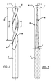
- the drill bit 10 includes a shank end 12, a working end 14 and a helical flute portion 16 positioned between the shank end and the working end.
- the shank end 12 has a desired diameter so that it may be positioned into a chuck of a hand held drill as well as a chuck of a stationary drill press.
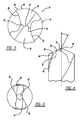
- the working end 14 may have a split point design including primary cutting edges 20 and 22, chisel edge 24 and secondary cutting edges 26, 28 as best seen in FIG. 3 .
- the primary cutting edges 20 and 22 are defined by a clearance face 30 and a rake face 32.
- the clearance face 30 is on an angle of about 10° to 14° and the rake face 32 is at an angle of about 34° to 36°.
- the rake face 32 and clearance face 30 define the primary cutting edges 20, 22.
- the secondary cutting edges 26 and 28 are defined by a clearance face 30 which is the same for the primary cutting edge.
- a rake face 34 is formed during a wheel grind of the working end 14 to form the split point (see FIG. 4 ).
- the clearance face 30 is on an angle of about 10° to 14° and the rake face 34 is at an angle of about 3° to 5°.
- the rake face 34 and clearance face 30 define the secondary cutting edges 26, 28.
- the chisel edge 24 has a length of about 0.11 to 0.32 mm, e.g., approximately 0.25 to 0.35 mm.
- the chisel edge 24 is between the primary 20, 22 and secondary 26, 28 cutting edges.
- the chisel edge 24 length increases the strength of the drill bit during drill press cutting.
- the helical flute portion 16 extends from the working end 14 to the shank end 12.
- a ratio of the diameter to the helix length 36 of the drill bit 10 is from about 1:4 to 1:5. e.g., between 1:4.5 to 1:4.75. In one embodiment, the ratio is 1:4.66.
- the helical flute portion 16 has a parabolic flute as best seen in FIG. 5 .
- the helix angle ⁇ is about 34° to 36°.
- the helical flute portion 16 includes a pair of margins 40.
- the margins 40 have a width length of about 8% to 12% of the diameter.
- the lands 44 including the margins 40 define the outer diameter of the drill bit 10. The helix length improves the speed of cutting of the drill bit.
- the drill bit 10 includes a tapered core 42 that extends from and increases in thickness from the working end 14 to the chucking end 12 as see in FIG. 2 .
- the tapered core 42 has a thickness (K) at the working end of between 10% to 35% of the diameter, e.g., between 15% to 25%. In one embodiment, the thickness (K) at the working end is 19% of the diameter.
- the thickness (J) at the chucking end is between 70% to 90% of the diameter, e.g., between 80% to 90%. In one embodiment, the thickness (J) is 87% of the diameter.
- a ratio (K:J) of the thickness of the taper at the tip to the junction at the shank portion is between 1:2 to 1:5 mm, e.g., 1:4 to 1:5. In one embodiment, the ratio (K:J) is 1:4.58.
- the taper thickness at the working edge enhances the speed and constant force cutting of the drill bit.
- the taper thickness at the rear of the drill bit enhances cutting and the robustness of the drill bit to enhance its strength during repetitive cutting on a stationary drill press. It is believed that the dramatically large web taper rate is one important factor in the success of this present drill bits.
- the drill bit is ordinarily made from high speed steel.
- the high speed steel includes cobalt in the presence of about 5% to 8% by weight. This increases the drill bit's resistance to heat during cutting in a stationary drill press. Additionally, the drill bit may be manufactured from materials such as M42 steel and WKE42 steel.
- the drill bit may include a coating layer that is vapor deposited onto the drill bit.
- the coating has a desired thickness of about 2 to 5 microns.
- the coating may be selected from a group comprising aluminum chromate, titanium aluminum nitride or combinations thereof.
- the coating provides a resistance to heat as well as "slip" or an increase in the cutting speed of the drill bit under high forces like those applied during cutting on a stationary drill press.
- the present drill bits are formed with the helix and placed into a loading bin.
- the drill bits are heated with hot air at a temperature between 70°C-90°C for about 10 minutes.
- the drill bits are transferred into a salt bath in a first oven heated to a temperature between 830°C-870°C for about 2 minutes.
- the drill bits are transferred into a salt bath in a second oven heated to a temperature between 1030°C -1070°C for about 2 minutes.
- the drill bits are transferred into a salt bath in a third oven heated to a temperature between 1160°C and 1190°C for about 80-120 seconds.
- the drill bits are transferred onto a salt bath quench in a fourth oven heated to a temperature between 530°C -570°C for about 2 minutes.
- the drill bits are transferred into a salt bath quench in a fifth oven heated to a temperature between 530°C -570°C for about 2 minutes.
- the drill bits are unloaded from the oven and cleaned and tempered. Tempering is accomplished by heating the drill bits up a temperature between 530°C-590°C and holding the drill bits at this temperature for about 1.5 hours.
- the drill bits are cooled to about 40°C.
- the tempering step is conducted two more times. This hardens the tempered drill bits to have a hardness of between 66 to 69 HRC.
- the drill bit is suitable for use in a hand-held drill.
- a user drills a hole in a workpiece using a hand-held drill
- the user generally applies a low constant force onto the drill in order to drill a hole.
- the drill bit becomes dull, the user will determine that the drill bit is worn out after it does not cut a hole in a reasonable amount of time.
- the present drill bit 10 during hand held drilling, provides for the drilling of at least approximately 15 holes, each drilled in less than approximately 90 seconds when drilling metal such as 304 stainless steel.
- the drilling of holes using a hand-held drill was simulated in a constant bias, or force test, by using an Orwin test rig.
- Orwin test rigs can be obtained at Orwin, Newcastle, UK.
- the Orwin test rig is utilized to life test drill bits where a constant bias is applied to the drill.
- a DeWalt® DW165 corded drill rotating at 1200 rpm with no load was utilized in the rig.
- the test material or workpiece was a 6 mm thick, 304 stainless steel.
- the low constant bias or force is applied onto the drill with a 1 ⁇ 4" diameter drill bit of the present invention.
- the low constant bias force is set at approximately 31 kg (68 lbs). Acceptable hole drill times are under approximately 90 seconds. Above approximately 90 seconds, at a constant bias, the user believes the drill bit is worn out. Accordingly, the cutoff time for drilling the holes is 90 seconds or a total of 500 holes, whichever comes first.
- FIG. 6 A graph of the test is illustrated in FIG. 6 .
- exemplary drill bits of the present invention were able to drill between 30 to 50 holes with a drilling time for each hole ranging from approximately 17 seconds to approximately 90 seconds.
- the drill bits were able to drill at least 35 holes, with a drill time of less than 90 seconds for each hole, far exceeding the goal of at least 15 holes at 90 seconds per hole.
- the testing on the Orwin test rig show that the exemplary drill bits of the present invention achieve a speed of approximately 18 seconds, where the speed of cut of the drill bits is determined by an average bore time of the first five holes drilled.
- the drill bits of the present invention achieved a speed of cut of about 17 seconds, further showing the suitability of these drill bits for use in a hand-held drill.
- the drill bit is suitable for use in a stationary drill press.
- a user drills holes in a workpiece with a stationary drill press
- the user increases the force on the drill bit in order to maintain a constant cutting feed rate.
- the drill bit will catastrophically fail.
- Emco life rig can be obtained at Emco Salzburg, Austria.
- the rig utilizes a spindle speed at 750 rpm and the test material is 4140 steel. Holes are bored into the 4140 steel at a drilling depth of about 18 mm.
- the feed rate of the drill bit into the material is set at 0.006 inch per revolution.
- an increased force is applied in order to maintain the constant feed rate.
- the force is varied since as the drill bit becomes more dull, an increased force is continued to be applied.
- the cutoff point for the drill bit is catastrophic failure. That is, when the drill bit breaks.
- the drill bits of the present invention provided for the drilling of at least approximately 2,300 holes without catastrophic failure.
- Several exemplary drill bits of the present invention drilled at least approximately 3,000 holes, with some of these drill bits drilling in excess of 3,600 holes. This far exceeds the minimum requirements for a drill bit to be used in a drill press.
- Drill bits in accordance with the present invention were tested against existing drill bits that were identified as being the best on the market for hand held drill metal cutting and against existing drill bits that were identified as the best on the market for stationary drill press cutting (collectively the "Best of Class” drill bits). Applicant has found no drill bits that were designed for uses in both hand held drills and stationary drill presses.
- the bits used were quarter inch (1 ⁇ 4") diameter DeWalt ® black oxide drill bits.
- the bits used were quarter inch (1 ⁇ 4") Dormer drill bits and quarter inch (1 ⁇ 4") Kennedy /Cle-Line drill bits. These drill bits were tested for speed of cut in the constant biasing force test (to simulate hand held cutting) as well as for life in the constant cutting feed rate test (to simulate drill press cutting). Accordingly, all of these drill bits were tested in the Orwin test rig, as identified above, to determine speed of cut with constant bias or force. Additionally, the three drill bits were tested in the Emco life rig, as described above, to determine a constant feed life. The results of the DeWalt drill bits, Dormer drill bits and Kennedy/Cle-Line drill bits are illustrated below.
- DeWalt ® black oxide drill bits (DW1163) were tested as described. This drill bit is designed for hand held drill metal cutting only. During the constant bias test (to simulate hand held drilling), the DeWalt ® black oxide drill bits had an average speed of cut of about 17.8 seconds (which is the average speed for drilling the first five holes). Additionally, the DeWalt ® black oxide drill bits drilled an average of 31 holes in less than 90 seconds per hole during the constant bias test. However, in the constant feed test (to simulate drill press drilling), the DeWalt ® black oxide drill bits drilled only an average of 1,778 holes before failure.
- Kennedy/Cle-Line drill bits (6.40 mm XT33 WP CO SS JBR DRL BRZ HSCo8 T7) (Cle-Line is a product of Kennametal Company, Inc.) were tested as described above.
- the Kennedy/Cle-Line drill bit is a stationary drill press drill bit.
- the Kennedy/Cle-Line drill bits had an average speed of cut of about 24.2 seconds, and drilled only an average of 15 holes at 90 seconds or less per hole.
- the Kennedy/Cle-Line drill bits drilled an average of 1,609 holes during the constant feed test.
- the "Best of Class" drill bits provide a bench mark for a drill bit to be used in a hand held drill as well as a stationary drill press. Thus, it is desired that a drill bit have a speed of cut of less than 18 seconds per hole for the first five holes. Additionally, the drill bit should cut at least 15 holes during the constant biasing test. Additionally, the drill bits should drill at least 2,300 holes during a constant feed test.
- drill bits in accordance with the present invention were tested as described above.
- Quarter inch (1 ⁇ 4") drill bits in accordance with the invention were tested.
- the quarter inch (1 ⁇ 4") diameter experimental drill bits manufactured from an M42 steel with an aluminum chromate coating were tested.
- the drill bits had an average speed of cut of 18.88 seconds, and drilled an average of 30 holes testing 90 seconds or less per hole.
- the drill bits drilled an average of 3,600 holes without failure.
- the drill bits of the present invention provide superior results when tested with respect to the Best in Class drill bits for their particular cutting environment.
- the present invention provided drill bits which exceed the performance of all the Best in Class features of the Best in Class drill bits in both hand held drilling and in drill press drilling.
Landscapes
- Engineering & Computer Science (AREA)
- Mechanical Engineering (AREA)
- Drilling Tools (AREA)
Abstract
A combination drill bit for use in both hand held drills and stationary drill presses has a shank end, a working end and a helical flute portion between the shank and working ends. The helical portion has a helix length (L) of 
The drill bit has a core that is tapered from the working end to the shank end. A web thickness length at the working end is 10% to 35% of the diameter and the thickness length at the junction of the shank end is 70% to 90% of the diameter. The drill bit is manufactured from a high speed steel including at least 5% by weight of cobalt.
Description
- The present invention relates to drill bits, especially metal cutting drill bits and, more particularly, to a metal cutting drill bit that can be used in both hand held drills as well as stationary drill presses.
- Ordinarily, two different types of drill bits are utilized in hand held drills and in stationary drill presses. In a hand held drill, the user is primarily interested in the cutting speed. Accordingly, the drill bit is designed to cut rapidly through the workpiece. In order to do this, the drill bit has very aggressive cutting angles. Thus, the relief angles, helical angles and cutting angles are designed to rapidly cut through a workpiece. Also, hand held drill users generally apply relatively constant, small forces to the drill during operation. High speed steel generally can be utilized as the material for the drill bit.
- In a stationary drill press, life of the drill bit generally is most important to the user. Speed is generally a secondary consideration. In stationary drill presses, a variable force that is larger than that used in a hand-held drill is applied to the drill bit. Thus, as the drill bit dulls, an increased force is applied to maintain the same feed rate. Stationary drill presses are concerned with drilling a large number of holes in a reasonable time. Thus, a drill bit for a stationary drill press has less aggressive cutting angles and a larger chisel edge. This provides for additional stability during use of the drill bit. Also, the drill bits are designed to dissipate and minimize heat that occurs at the working tip during use.
- A drill bit designed for a hand held drill is not stable enough, when utilized in a stationary drill press, so that failure occurs after a small number of holes are formed in a workpiece. Additionally, the drill bit is incapable of dissipating large amounts of heat that occurs at the working tip when it is utilized in a stationary drill press. Accordingly, hand held drill bits fail relatively quickly in a stationary drill press.
- Drill bits designed for stationary drill presses do not cut fast enough to be used in a hand held drill. Also, due to their ability to dissipate heat, the material used for their manufacturing is brittle. Accordingly, lateral loads applied to these drill bits cause failure. Thus, since the design factors for drill bits used in stationary drill presses is diametrically opposite to drill bits used in hand held drills, the technologies have not been combined to provide a drill bit that functions satisfactorily in both hand held drilling applications as well as in stationary drill press applications.
- Accordingly, it is an object of the present invention to provide a drill bit that is suitable for both hand held drills as well as stationary drill presses. The present invention provides a drill bit that normally performs well in both hand held and stationary drilling. Additionally, the drill bit normally provides cutting of a satisfactory number of holes using it in a hand held drill within a specified amount of time. Additionally, the same drill bit normally drills a large number of holes when utilized in a stationary drill press.
- The present invention provides a drill bit, preferably a combination drill bit for hand held drill and drill press drilling, which comprises a shank end, a working end, and a helical flute portion between the shank end and the working end. The helical flute portion has a web that tapers, preferably from the working end to the shank end. The web thickness preferably is at a ratio (K:J), of the working end (K) to the junction (J) at the shank end, of about 1:2 to 1:5. The helical flute portion preferably has a helix length (L) of

- Additionally, the drill bit preferably is manufactured from a high speed steel material having at least 5% by weight of cobalt. The drill bit may be vapor vacuum coated including a layer of aluminum carbide, titanium aluminum nitride or combinations thereof. The working point may be a split point with a chisel edge having a length from about .11 to .32 mm. The drill bit may be hardened at a temperature between 1160° to 1190°C.
- A second aspect of the invention provides a drill bit, preferably a combination drill bit for a hand held drill and a stationary drill press, which comprises a shank end, a working end, and a helical flute portion between said shank end and said working end. The helical flute portion preferably has a web that tapers from the working end to the shank end. The web taper rate (which is the difference between the web thickness at the working end (K) and the web thickness at the junction of the tapered web and the shank end (J), divided by the length of the tapered section (L) preferably is at least approximately 0.080. The helical flute portion preferably has a helix length (L) of about Additionally, the drill bit may be manufactured from a high speed steel material having at least 5% by weight of cobalt. Additionally, a coating layer may be applied to the drill bit. The drill bit preferably drills at least approximately 15 holes during a constant bias life test or at least approximately 2,300 holes during a constant feed life test.
- According to a third aspect of the invention, a method of drilling a workpiece using a hand held drill or a stationary drill press using the same drill bit in both, comprises chucking the drill bit in the hand held drill, drilling at least approximately 15 holes using the hand held drill, and/or chucking the drill bit in the stationary drill press, and drilling at least approximately 2,300 holes in a workpiece using the stationary drill press. The hand held drill drills each hole in a time period of less than approximately 90 seconds. The drilling of the at least approximately 2,300 holes in the drill press occurs without failure of the bit.
- Preferably, the first five holes are drilled into the workpiece using the hand held drill in approximately 18 seconds per hole or less. Preferably, drilling at least 15 holes in a workpiece using the hand held drill in less than approximately 90 seconds per hole comprises drilling at least approximately 15 holes through approximately 6 mm thick 304 stainless steel using the hand-held drill, or an experimental simulation thereof, operating at approximately 1200 rpm with a constant bias of a approximately 31 kg, each hole being drilled in less than approximately 90 seconds. Advantageously, drilling at least 2,300 holes in a workpiece using the drill press comprises drilling at least approximately 2,300 bores each having a depth of at least approximately 18 mm in 4140 steel, using the drill press, or an experimental simulation thereof, operating with a spindle speed of approximately 750 rpm and a feed rate of approximately 0.006 inch per revolution.
- Further areas of applicability will become apparent from the description provided herein.
- Embodiments of the invention will now be described, by way of example, with reference to the accompanying drawings, of which:
- FIG. 1
- is a plan view of a drill bit;
- FIG. 2
- is a longitudinal cross section view of the drill bit of
FIG. 1 ; - FIG. 3
- is a plan view of the working tip of the drill bit of
FIG. 1 ; - FIG. 4
- is a perspective view of the working tip of the drill bit of
FIG. 1 ; - FIG. 5
- is a cross-section view of the drill bit of
FIG. 1 along line 5-5 thereof; and - FIG. 6
- is a graph of results of the constant bias life test.
- Important drilling factors are speed, constant bias life and constant feed life of the drill bit. It has been found that speed is influenced by the thickness of the web at the working end. Also, it has been found that speed is also influenced by the helix length of the drill bit. It has been found that constant bias life is influenced by the web thickness at the working end of the drill bit. Additionally, the constant feed life is increased by the tapered thickness at the junction of the shank. Accordingly, during testing of the drill bits, it was found that utilizing parameters that are contrary to use in a hand held or stationary drill press provided excellent results for the present drill bit. Accordingly, the disclosed drill bit provides a single drill bit that may be utilized in both a hand held drill and a stationary drill press. The drill bits provide excellent results in both applications eliminating the need for separate drill bits to be utilized in both applications.
- Referring to the figures, a drill bit is illustrated and designated with the
reference numeral 10. Thedrill bit 10 includes ashank end 12, a workingend 14 and ahelical flute portion 16 positioned between the shank end and the working end. Theshank end 12 has a desired diameter so that it may be positioned into a chuck of a hand held drill as well as a chuck of a stationary drill press. - The working
end 14 may have a split point design including primary cutting edges 20 and 22,chisel edge 24 and secondary cutting edges 26, 28 as best seen inFIG. 3 . The primary cutting edges 20 and 22 are defined by aclearance face 30 and arake face 32. Theclearance face 30 is on an angle of about 10° to 14° and therake face 32 is at an angle of about 34° to 36°. Therake face 32 and clearance face 30 define the primary cutting edges 20, 22. - The secondary cutting edges 26 and 28 are defined by a
clearance face 30 which is the same for the primary cutting edge. Arake face 34 is formed during a wheel grind of the workingend 14 to form the split point (seeFIG. 4 ). Theclearance face 30 is on an angle of about 10° to 14° and therake face 34 is at an angle of about 3° to 5°. Therake face 34 and clearance face 30 define the secondary cutting edges 26, 28. - The
chisel edge 24 has a length of about 0.11 to 0.32 mm, e.g., approximately 0.25 to 0.35 mm. Thechisel edge 24 is between the primary 20, 22 and secondary 26, 28 cutting edges. Thechisel edge 24 length increases the strength of the drill bit during drill press cutting. - The
helical flute portion 16 extends from the workingend 14 to theshank end 12. Thehelical flute portion 16 has a helix length (L) 36 defined by the equation
helix length 36 of thedrill bit 10 is from about 1:4 to 1:5. e.g., between 1:4.5 to 1:4.75. In one embodiment, the ratio is 1:4.66. Thehelical flute portion 16 has a parabolic flute as best seen inFIG. 5 . The helix angle α is about 34° to 36°. Additionally, thehelical flute portion 16 includes a pair ofmargins 40. Themargins 40 have a width length of about 8% to 12% of the diameter. Thelands 44 including themargins 40 define the outer diameter of thedrill bit 10. The helix length improves the speed of cutting of the drill bit. - The
drill bit 10 includes a taperedcore 42 that extends from and increases in thickness from the workingend 14 to the chuckingend 12 as see inFIG. 2 . The taperedcore 42 has a thickness (K) at the working end of between 10% to 35% of the diameter, e.g., between 15% to 25%. In one embodiment, the thickness (K) at the working end is 19% of the diameter. The thickness (J) at the chucking end is between 70% to 90% of the diameter, e.g., between 80% to 90%. In one embodiment, the thickness (J) is 87% of the diameter. Thus, a ratio (K:J) of the thickness of the taper at the tip to the junction at the shank portion is between 1:2 to 1:5 mm, e.g., 1:4 to 1:5. In one embodiment, the ratio (K:J) is 1:4.58. The web tapers at a rate defined by the difference between the web thickness at the shank end (J) and the web thickness at the working end (K), divided by the length of the tapered section (L). In one embodiment, the web taper rate is at least 0.080. The taper thickness at the working edge enhances the speed and constant force cutting of the drill bit. The taper thickness at the rear of the drill bit enhances cutting and the robustness of the drill bit to enhance its strength during repetitive cutting on a stationary drill press. It is believed that the dramatically large web taper rate is one important factor in the success of this present drill bits. - The drill bit is ordinarily made from high speed steel. The high speed steel includes cobalt in the presence of about 5% to 8% by weight. This increases the drill bit's resistance to heat during cutting in a stationary drill press. Additionally, the drill bit may be manufactured from materials such as M42 steel and WKE42 steel.
- The drill bit may include a coating layer that is vapor deposited onto the drill bit. The coating has a desired thickness of about 2 to 5 microns. The coating may be selected from a group comprising aluminum chromate, titanium aluminum nitride or combinations thereof. The coating provides a resistance to heat as well as "slip" or an increase in the cutting speed of the drill bit under high forces like those applied during cutting on a stationary drill press.
- The present drill bits are formed with the helix and placed into a loading bin. The drill bits are heated with hot air at a temperature between 70°C-90°C for about 10 minutes. The drill bits are transferred into a salt bath in a first oven heated to a temperature between 830°C-870°C for about 2 minutes. The drill bits are transferred into a salt bath in a second oven heated to a temperature between 1030°C -1070°C for about 2 minutes. The drill bits are transferred into a salt bath in a third oven heated to a temperature between 1160°C and 1190°C for about 80-120 seconds. The drill bits are transferred onto a salt bath quench in a fourth oven heated to a temperature between 530°C -570°C for about 2 minutes. The drill bits are transferred into a salt bath quench in a fifth oven heated to a temperature between 530°C -570°C for about 2 minutes. The drill bits are unloaded from the oven and cleaned and tempered. Tempering is accomplished by heating the drill bits up a temperature between 530°C-590°C and holding the drill bits at this temperature for about 1.5 hours. The drill bits are cooled to about 40°C. The tempering step is conducted two more times. This hardens the tempered drill bits to have a hardness of between 66 to 69 HRC.
- Experiments show that the drill bit is suitable for use in a hand-held drill. When a user drills a hole in a workpiece using a hand-held drill, it has been found that the user generally applies a low constant force onto the drill in order to drill a hole. As the drill bit becomes dull, the user will determine that the drill bit is worn out after it does not cut a hole in a reasonable amount of time. Accordingly, the
present drill bit 10, during hand held drilling, provides for the drilling of at least approximately 15 holes, each drilled in less than approximately 90 seconds when drilling metal such as 304 stainless steel. The drilling of holes using a hand-held drill was simulated in a constant bias, or force test, by using an Orwin test rig. Orwin test rigs can be obtained at Orwin, Newcastle, UK. The Orwin test rig is utilized to life test drill bits where a constant bias is applied to the drill. A DeWalt® DW165 corded drill rotating at 1200 rpm with no load was utilized in the rig. Generally, the test material or workpiece was a 6 mm thick, 304 stainless steel. The low constant bias or force is applied onto the drill with a ¼" diameter drill bit of the present invention. The low constant bias force is set at approximately 31 kg (68 lbs). Acceptable hole drill times are under approximately 90 seconds. Above approximately 90 seconds, at a constant bias, the user believes the drill bit is worn out. Accordingly, the cutoff time for drilling the holes is 90 seconds or a total of 500 holes, whichever comes first. Thus, if the drill bit fails to drill the hole within a 90 second time range, it is considered to have failed the test. A graph of the test is illustrated inFIG. 6 . As shown inFig. 6 , on average, exemplary drill bits of the present invention were able to drill between 30 to 50 holes with a drilling time for each hole ranging from approximately 17 seconds to approximately 90 seconds. In one example, the drill bits were able to drill at least 35 holes, with a drill time of less than 90 seconds for each hole, far exceeding the goal of at least 15 holes at 90 seconds per hole. - In addition, the testing on the Orwin test rig show that the exemplary drill bits of the present invention achieve a speed of approximately 18 seconds, where the speed of cut of the drill bits is determined by an average bore time of the first five holes drilled. For example, the drill bits of the present invention achieved a speed of cut of about 17 seconds, further showing the suitability of these drill bits for use in a hand-held drill.
- Experiments also show that the drill bit is suitable for use in a stationary drill press. When a user drills holes in a workpiece with a stationary drill press, the user increases the force on the drill bit in order to maintain a constant cutting feed rate. As the force is varied and increased, if the drill bit does not keep up its constant feed rate due to the increase force, the drill bit will catastrophically fail. In order to simulate the life of the drill bit in a stationary drill press, a constant feed life test was performed using an Emco life rig. Emco rigs can be obtained at Emco Salzburg, Austria. The rig utilizes a spindle speed at 750 rpm and the test material is 4140 steel. Holes are bored into the 4140 steel at a drilling depth of about 18 mm. The feed rate of the drill bit into the material is set at 0.006 inch per revolution. Thus, as the drill bit becomes dull, an increased force is applied in order to maintain the constant feed rate. Accordingly, the force is varied since as the drill bit becomes more dull, an increased force is continued to be applied. The cutoff point for the drill bit is catastrophic failure. That is, when the drill bit breaks. During the constant feed life test using the Emco rig, the drill bits of the present invention provided for the drilling of at least approximately 2,300 holes without catastrophic failure. Several exemplary drill bits of the present invention drilled at least approximately 3,000 holes, with some of these drill bits drilling in excess of 3,600 holes. This far exceeds the minimum requirements for a drill bit to be used in a drill press.
- Drill bits in accordance with the present invention were tested against existing drill bits that were identified as being the best on the market for hand held drill metal cutting and against existing drill bits that were identified as the best on the market for stationary drill press cutting (collectively the "Best of Class" drill bits). Applicant has found no drill bits that were designed for uses in both hand held drills and stationary drill presses.
- Three Best of Class bits were tested. For hand held metal cutting, the bits used were quarter inch (¼") diameter DeWalt® black oxide drill bits. For drill press cutting, the bits used were quarter inch (¼") Dormer drill bits and quarter inch (¼") Kennedy /Cle-Line drill bits. These drill bits were tested for speed of cut in the constant biasing force test (to simulate hand held cutting) as well as for life in the constant cutting feed rate test (to simulate drill press cutting). Accordingly, all of these drill bits were tested in the Orwin test rig, as identified above, to determine speed of cut with constant bias or force. Additionally, the three drill bits were tested in the Emco life rig, as described above, to determine a constant feed life. The results of the DeWalt drill bits, Dormer drill bits and Kennedy/Cle-Line drill bits are illustrated below.
- Quarter inch (¼") diameter DeWalt® black oxide drill bits (DW1163) were tested as described. This drill bit is designed for hand held drill metal cutting only. During the constant bias test (to simulate hand held drilling), the DeWalt® black oxide drill bits had an average speed of cut of about 17.8 seconds (which is the average speed for drilling the first five holes). Additionally, the DeWalt® black oxide drill bits drilled an average of 31 holes in less than 90 seconds per hole during the constant bias test. However, in the constant feed test (to simulate drill press drilling), the DeWalt® black oxide drill bits drilled only an average of 1,778 holes before failure.
- Quarter inch (¼") Dormer drill bits (A577 6.40 mm HSCO PFX ALTIN COATED JOBBER DRILL) (Dormer is a brand of Sandvik Company) were tested as described above. The Dormer drill bit is a stationary drill press drill bit. During the constant bias test (to simulate hand held drilling), the Dormer drill bits were unable to cut even a single hole in 90 seconds or less, thus failing the test. During the constant feed life test (to simulate drill press drilling), the Dormer drill bits drilled an average of 2,311 holes before failure.
- Quarter inch (¼") Kennedy/Cle-Line drill bits (6.40 mm XT33 WP CO SS JBR DRL BRZ HSCo8 T7) (Cle-Line is a product of Kennametal Company, Inc.) were tested as described above. The Kennedy/Cle-Line drill bit is a stationary drill press drill bit. During the constant bias test (to simulate hand held drilling), the Kennedy/Cle-Line drill bits had an average speed of cut of about 24.2 seconds, and drilled only an average of 15 holes at 90 seconds or less per hole. During the constant feed life test (to simulate drill press drilling, the Kennedy/Cle-Line drill bits drilled an average of 1,609 holes during the constant feed test.
- The "Best of Class" drill bits provide a bench mark for a drill bit to be used in a hand held drill as well as a stationary drill press. Thus, it is desired that a drill bit have a speed of cut of less than 18 seconds per hole for the first five holes. Additionally, the drill bit should cut at least 15 holes during the constant biasing test. Additionally, the drill bits should drill at least 2,300 holes during a constant feed test.
- Having benchmarks from the Best in Class drill bits, drill bits in accordance with the present invention were tested as described above.
- Quarter inch (¼") diameter experimental drill bits manufactured from M42 steel with a titanium aluminum nitride coating were tested. In the constant bias test (to simulate hand held drilling), the drill bits had an average speed of cut of 17.3 seconds per hole for the first five holes, and drilled an average of 49 holes at a rate of 90 seconds per hole or less. During the constant feed test (to simulate drill press drilling), the drill bits drilled an average of 3,074 holes before failure.
- Quarter inch (¼") drill bits in accordance with the invention were tested. The quarter inch (¼") diameter experimental drill bits manufactured from an M42 steel with an aluminum chromate coating were tested. In the constant bias test (to simulate hand held drilling), the drill bits had an average speed of cut of 18.88 seconds, and drilled an average of 30 holes testing 90 seconds or less per hole. In the constant feed test (to simulate drill press drilling), the drill bits drilled an average of 3,600 holes without failure.
- Thus, the drill bits of the present invention provide superior results when tested with respect to the Best in Class drill bits for their particular cutting environment. The present invention provided drill bits which exceed the performance of all the Best in Class features of the Best in Class drill bits in both hand held drilling and in drill press drilling.
- The foregoing description of the embodiments has been provided for purposes of illustration and description. Individual elements or features of a particular embodiment are generally not limited to that particular embodiment, but, where applicable, are interchangeable and can be used in a selected embodiment, even if not specifically shown or described.
Claims (7)
- A drill bit, comprising:a shank end;a working end;a helical flute portion between said shank end and said working end, said helical flute portion having a tapered web having a web taper rate of at least approximately 0.080; and wherein:the helical flute portion has a helix length L defined by:
 where D is the bit diameter, and α is the helix angle; andsaid drill bit comprises a high speed steel material having at least 5% cobalt, by weight.
 - A drill bit according to claim 1, which is capable of drilling at least 15 holes through 6 mm thick 304 stainless steel using a hand-held drill, or an experimental simulation thereof, operating at 1200 rpm with a constant bias of 31 kg, each hole being drilled in less than 90 seconds.
- A drill bit according to one of claims 1 and 2, which is capable of drilling at least 2,300 bores each having a depth of at least 18 mm in 4140 steel, using a drill press, or an experimental simulation thereof, operating with a spindle speed 750 rpm and a feed rate of 0.006 inch per revolution.
- A drill bit according to any one of claims 1-3, further comprising a coating layer of AlCr, TiAlN or combinations thereof.
- A drill bit according to any one of claims 1-4, wherein the high speed steel comprises at least one of M42 steel and WKE42 steel.
- A drill bit according to any one of claims 1-5, wherein said working end comprises a split point having a chisel edge length of approximately .011 mm to approximately 0.32 mm.
- A drill bit according to any one of claims 1-6, wherein said drill bit comprises a material that has been hardened at a temperature between 1160° to 1190°C.
Applications Claiming Priority (2)
| Application Number | Priority Date | Filing Date | Title |
|---|---|---|---|
| US9382708P | 2008-09-03 | 2008-09-03 | |
| US12/539,831 US8740515B2 (en) | 2008-09-03 | 2009-08-12 | Metal cutting drill bit |
Publications (1)
| Publication Number | Publication Date |
|---|---|
| EP2161089A1 true EP2161089A1 (en) | 2010-03-10 |
Family
ID=41131779
Family Applications (1)
| Application Number | Title | Priority Date | Filing Date |
|---|---|---|---|
| EP09169346A Withdrawn EP2161089A1 (en) | 2008-09-03 | 2009-09-03 | Drill Bit |
Country Status (3)
| Country | Link |
|---|---|
| US (1) | US8740515B2 (en) |
| EP (1) | EP2161089A1 (en) |
| CN (1) | CN201895117U (en) |
Families Citing this family (24)
| Publication number | Priority date | Publication date | Assignee | Title |
|---|---|---|---|---|
| US7950880B2 (en) * | 2006-10-18 | 2011-05-31 | Kennametal Inc. | Spiral flute tap |
| IL211236A0 (en) * | 2011-02-15 | 2011-04-28 | Vladimir Volokh | Rotary cutter |
| EP2502710B1 (en) | 2011-03-22 | 2020-04-22 | Black & Decker Inc. | Chisels |
| FR2991209B1 (en) * | 2012-06-05 | 2015-07-03 | Snecma | CALIBRATION HEAD FOR TREE DRILLING |
| USD734792S1 (en) | 2013-03-15 | 2015-07-21 | Black & Decker Inc. | Drill bit |
| US9333564B2 (en) * | 2013-03-15 | 2016-05-10 | Black & Decker Inc. | Drill bit |
| USD737875S1 (en) | 2013-03-15 | 2015-09-01 | Black & Decker Inc. | Drill bit |
| EP2990145B1 (en) | 2013-04-26 | 2020-01-22 | KYOCERA Corporation | Drill and method for manufacturing cut product using same |
| US9731358B2 (en) | 2013-06-06 | 2017-08-15 | Milwaukee Electric Tool Corporation | Step drill bit |
| EP2842673B1 (en) * | 2013-08-29 | 2018-11-21 | Black & Decker Inc. | Drill bit |
| EA030660B1 (en) * | 2014-05-20 | 2018-09-28 | Наталино Капоне | Drilling tool |
| USD724126S1 (en) * | 2014-05-27 | 2015-03-10 | Fraisa Sa | Drilling and milling device |
| CN104607722A (en) * | 2015-02-02 | 2015-05-13 | 苏州阿诺精密切削技术股份有限公司 | High precision forming reamer |
| JP6747791B2 (en) * | 2015-08-31 | 2020-08-26 | 株式会社Subaru | Method for manufacturing drill and perforated product |
| USD854062S1 (en) * | 2016-09-02 | 2019-07-16 | Robert Bosch Gmbh | Drill bit |
| JP1568741S (en) * | 2016-09-09 | 2017-02-06 | ||
| JP1581012S (en) * | 2016-11-17 | 2017-07-10 | ||
| IL249676B (en) * | 2016-12-20 | 2021-08-31 | Hanita Metal Works Ltd | End mills having differential twisted gash profiles |
| CN209849949U (en) | 2018-01-29 | 2019-12-27 | 米沃奇电动工具公司 | drill |
| US11273501B2 (en) | 2018-04-26 | 2022-03-15 | Milwaukee Electric Tool Corporation | Step drill bit |
| US11679442B2 (en) | 2018-06-22 | 2023-06-20 | Maestro Logistics, Llc | Drill bit and method for making a drill bit |
| USD937913S1 (en) * | 2020-12-07 | 2021-12-07 | Danyang Youjie Tools Co., Ltd. | Drill bit |
| US20230089637A1 (en) * | 2021-09-17 | 2023-03-23 | Apex Brands, Inc. | Twist drill bit |
| US11865629B2 (en) | 2021-11-04 | 2024-01-09 | Kennametal Inc. | Rotary cutting tool with high ramp angle capability |
Citations (5)
| Publication number | Priority date | Publication date | Assignee | Title |
|---|---|---|---|---|
| WO1988001214A1 (en) * | 1986-08-18 | 1988-02-25 | Black & Decker Inc. | Self-centering drill bit with pilot tip |
| EP0893185A1 (en) * | 1997-05-29 | 1999-01-27 | Black & Decker Inc. | Twist drill |
| DE20312819U1 (en) * | 2003-08-14 | 2003-10-09 | MK Werkzeug-Service Manfred Krystek e.K., 07318 Saalfeld | Welding point drill used in the car industry for welding chassis sheets comprises a receiving shaft and a drill head having concave cutting edges with a front and a rear free surface and a centering tip with cross cutters |
| EP1512476A2 (en) * | 2003-09-08 | 2005-03-09 | BLACK & DECKER INC. | Self-centering drill bit with pilot tip |
| US20060056930A1 (en) * | 2004-09-07 | 2006-03-16 | Markus Rompel | Twist drill with a pilot tip |
Family Cites Families (27)
| Publication number | Priority date | Publication date | Assignee | Title |
|---|---|---|---|---|
| DE7335696U (en) | 1973-12-20 | Odenwald Faserplattenwerk Gmbh | Kit for cross connector | |
| DE216607C (en) | ||||
| BE524021A (en) * | 1951-10-12 | |||
| US3387511A (en) | 1966-05-02 | 1968-06-11 | Lockheed Aircraft Corp | Twist drill |
| ES2029456T3 (en) | 1986-06-07 | 1992-08-16 | Hertel Aktiengesellschaft Werkzeuge + Hartstoffe | PROCEDURE FOR SHARPENING A SPIRAL DRILL. |
| US4756650A (en) * | 1986-11-26 | 1988-07-12 | Kabushiki Kaisha Kobe Seiko Sho | Twist drill |
| US5230593A (en) * | 1987-12-14 | 1993-07-27 | Mitsubishi Kinzoku Kabushiki Kaisha | Twist drill |
| EP0320881B2 (en) | 1987-12-14 | 2003-10-22 | Mitsubishi Materials Corporation | Twist drill |
| US4898503A (en) * | 1988-07-05 | 1990-02-06 | Lockheed Corporation | Twist drill |
| DE3927615A1 (en) | 1989-08-22 | 1991-02-28 | Hartner Gmbh & Co Kg G | Drilling holes in nickel-chromium alloy steel - involves high speed steel with dimensions defined by formula |
| CH675842A5 (en) | 1990-01-18 | 1990-11-15 | Tungstentools S A | Twist drill with variable depth helix - has core with different diameter sections proportionate to spiral diameter and with specified conicity |
| DE4117486C2 (en) | 1991-05-28 | 1995-07-27 | Hitachi Seiko Kk | drill |
| US5350261A (en) * | 1992-03-12 | 1994-09-27 | Mitsubishi Materials Corporation | Twist drill |
| GB2303809A (en) | 1995-07-29 | 1997-03-05 | Black & Decker Inc | Roll-forged drill bit |
| JP2000511532A (en) | 1996-05-20 | 2000-09-05 | メルク エンド カンパニー インコーポレーテッド | Gonadotropin-releasing hormone antagonists |
| DE19726984A1 (en) | 1997-06-25 | 1999-01-07 | Kennametal Inc | Drills for dry drilling |
| DE29722002U1 (en) | 1997-12-15 | 1998-02-05 | Werkzeugfabrik GmbH Königsee, 07426 Königsee | Twist drill |
| DE20005730U1 (en) | 2000-03-28 | 2000-10-26 | Hartmetallwerkzeugfabrik Andreas Maier GmbH, 88477 Schwendi | Micro drill with two or more cutting edges, with main cutting edge correction and pointed cross-cutting edge, diameter 0.04 - 1 mm for the production of printed circuit boards |
| US20020166606A1 (en) * | 2001-03-12 | 2002-11-14 | Russell Caminiti | Method of coating a metal substrate |
| US6637987B2 (en) * | 2002-02-26 | 2003-10-28 | Choon Nang Electrical Appliance Mfy., Ltd. | Drill bit |
| SE525336C2 (en) * | 2002-05-17 | 2005-02-01 | Sandvik Ab | Drilling tools for hole drilling in metallic materials |
| DE20209767U1 (en) | 2002-06-24 | 2003-11-20 | Gühring, Jörg, Dr., 72458 Albstadt | Spiral drill bit for drilling holes in e.g. plastic, carbon fiber, or other sandwich material with e.g. a titanium layer. has a drill point with two main cutting areas and two intermediate cutters and two main grooves |
| DE20211589U1 (en) | 2002-07-15 | 2004-01-29 | Gühring, Jörg, Dr. | Drill bit for forming exact holes in a sandwich material, e.g. used in airplane construction, has minor cutting edges having positive chucking angles |
| BRPI0603856A (en) * | 2006-08-28 | 2008-04-15 | Villares Metals Sa | hard alloys of lean composition |
| DE102006049096A1 (en) | 2006-10-13 | 2008-04-17 | Kennametal Inc. | Drill bit for boring tool, has center-distal active edge section and inactive edge section limited to each other to inner edge corner, where distance of edge corner to drill middle axis is greater than or equal to core radius of drill core |
| AT505221B1 (en) * | 2007-05-08 | 2009-09-15 | Bihler Edelstahl Gmbh | TOOL WITH COATING |
| JP4505007B2 (en) | 2007-11-08 | 2010-07-14 | ユニオンツール株式会社 | Drilling tool |
-
2009
- 2009-08-12 US US12/539,831 patent/US8740515B2/en active Active
- 2009-09-03 EP EP09169346A patent/EP2161089A1/en not_active Withdrawn
- 2009-09-03 CN CN2009202913038U patent/CN201895117U/en not_active Expired - Fee Related
Patent Citations (5)
| Publication number | Priority date | Publication date | Assignee | Title |
|---|---|---|---|---|
| WO1988001214A1 (en) * | 1986-08-18 | 1988-02-25 | Black & Decker Inc. | Self-centering drill bit with pilot tip |
| EP0893185A1 (en) * | 1997-05-29 | 1999-01-27 | Black & Decker Inc. | Twist drill |
| DE20312819U1 (en) * | 2003-08-14 | 2003-10-09 | MK Werkzeug-Service Manfred Krystek e.K., 07318 Saalfeld | Welding point drill used in the car industry for welding chassis sheets comprises a receiving shaft and a drill head having concave cutting edges with a front and a rear free surface and a centering tip with cross cutters |
| EP1512476A2 (en) * | 2003-09-08 | 2005-03-09 | BLACK & DECKER INC. | Self-centering drill bit with pilot tip |
| US20060056930A1 (en) * | 2004-09-07 | 2006-03-16 | Markus Rompel | Twist drill with a pilot tip |
Also Published As
| Publication number | Publication date |
|---|---|
| US20100054881A1 (en) | 2010-03-04 |
| CN201895117U (en) | 2011-07-13 |
| US8740515B2 (en) | 2014-06-03 |
Similar Documents
| Publication | Publication Date | Title |
|---|---|---|
| US8740515B2 (en) | Metal cutting drill bit | |
| AU782864B2 (en) | Cutting tools and drill inserts with chip control geometry | |
| KR100838767B1 (en) | Twist drill | |
| US4815902A (en) | Stepped fluted drill | |
| US9156094B2 (en) | Step drill for wood | |
| US10399153B2 (en) | Rotary cutting tool including polycrystalline diamond material | |
| US7556459B2 (en) | Hole saw having a drill bit with a pilot tip | |
| US20060269372A1 (en) | Twist drill | |
| US6939092B2 (en) | Sheet metal hole cutter | |
| US20220371105A1 (en) | Step drill bits | |
| US12296395B2 (en) | Drill bit | |
| AU2007237362B2 (en) | Drill bit | |
| EP1660694B1 (en) | Coated bore cutting tools | |
| US11278970B2 (en) | Drill bit | |
| JP4996278B2 (en) | Long drill made of super hard material for deep hole machining | |
| EP4067029B1 (en) | Spade drill bits | |
| US7618220B2 (en) | Rotary tool | |
| JP5077996B2 (en) | Carbide twist drill | |
| EP2842673B1 (en) | Drill bit | |
| EP2643117B1 (en) | Bit for a rotary drill |
Legal Events
| Date | Code | Title | Description |
|---|---|---|---|
| PUAI | Public reference made under article 153(3) epc to a published international application that has entered the european phase |
Free format text: ORIGINAL CODE: 0009012 |
|
| AK | Designated contracting states |
Kind code of ref document: A1 Designated state(s): AT BE BG CH CY CZ DE DK EE ES FI FR GB GR HR HU IE IS IT LI LT LU LV MC MK MT NL NO PL PT RO SE SI SK SM TR |
|
| AX | Request for extension of the european patent |
Extension state: AL BA RS |
|
| 17P | Request for examination filed |
Effective date: 20100806 |
|
| 17Q | First examination report despatched |
Effective date: 20101012 |
|
| STAA | Information on the status of an ep patent application or granted ep patent |
Free format text: STATUS: THE APPLICATION IS DEEMED TO BE WITHDRAWN |
|
| 18D | Application deemed to be withdrawn |
Effective date: 20110427 |