EP2160452B1 - Procédé et système permettant d'éliminer le h2s d'un flux de gaz naturel - Google Patents
Procédé et système permettant d'éliminer le h2s d'un flux de gaz naturel Download PDFInfo
- Publication number
- EP2160452B1 EP2160452B1 EP08766847A EP08766847A EP2160452B1 EP 2160452 B1 EP2160452 B1 EP 2160452B1 EP 08766847 A EP08766847 A EP 08766847A EP 08766847 A EP08766847 A EP 08766847A EP 2160452 B1 EP2160452 B1 EP 2160452B1
- Authority
- EP
- European Patent Office
- Prior art keywords
- cooled
- gas stream
- natural gas
- hydrogen sulphide
- fraction
- Prior art date
- Legal status (The legal status is an assumption and is not a legal conclusion. Google has not performed a legal analysis and makes no representation as to the accuracy of the status listed.)
- Not-in-force
Links
- VNWKTOKETHGBQD-UHFFFAOYSA-N methane Chemical compound C VNWKTOKETHGBQD-UHFFFAOYSA-N 0.000 title claims abstract description 239
- 239000003345 natural gas Substances 0.000 title claims abstract description 65
- 238000000034 method Methods 0.000 title claims abstract description 46
- RWSOTUBLDIXVET-UHFFFAOYSA-N Dihydrogen sulfide Chemical compound S RWSOTUBLDIXVET-UHFFFAOYSA-N 0.000 claims abstract description 127
- 238000000926 separation method Methods 0.000 claims abstract description 65
- 239000012530 fluid Substances 0.000 claims abstract description 53
- 239000007789 gas Substances 0.000 claims abstract description 46
- 238000001816 cooling Methods 0.000 claims abstract description 21
- 230000001939 inductive effect Effects 0.000 claims abstract description 8
- 239000007788 liquid Substances 0.000 claims description 54
- 238000010992 reflux Methods 0.000 claims description 50
- XLYOFNOQVPJJNP-UHFFFAOYSA-N water Substances O XLYOFNOQVPJJNP-UHFFFAOYSA-N 0.000 claims description 22
- 238000010521 absorption reaction Methods 0.000 claims description 7
- 238000011144 upstream manufacturing Methods 0.000 claims description 6
- 239000002274 desiccant Substances 0.000 claims description 3
- 230000008569 process Effects 0.000 description 13
- 238000011084 recovery Methods 0.000 description 10
- 238000005194 fractionation Methods 0.000 description 8
- 150000001412 amines Chemical class 0.000 description 7
- CURLTUGMZLYLDI-UHFFFAOYSA-N Carbon dioxide Chemical compound O=C=O CURLTUGMZLYLDI-UHFFFAOYSA-N 0.000 description 5
- 241001589086 Bellapiscis medius Species 0.000 description 4
- 229910002092 carbon dioxide Inorganic materials 0.000 description 3
- 208000028659 discharge Diseases 0.000 description 3
- 239000004215 Carbon black (E152) Substances 0.000 description 2
- ATUOYWHBWRKTHZ-UHFFFAOYSA-N Propane Chemical compound CCC ATUOYWHBWRKTHZ-UHFFFAOYSA-N 0.000 description 2
- NINIDFKCEFEMDL-UHFFFAOYSA-N Sulfur Chemical compound [S] NINIDFKCEFEMDL-UHFFFAOYSA-N 0.000 description 2
- 239000005864 Sulphur Substances 0.000 description 2
- 239000001569 carbon dioxide Substances 0.000 description 2
- 238000007599 discharging Methods 0.000 description 2
- 229930195733 hydrocarbon Natural products 0.000 description 2
- 150000002430 hydrocarbons Chemical class 0.000 description 2
- 239000000203 mixture Substances 0.000 description 2
- 230000009467 reduction Effects 0.000 description 2
- OTMSDBZUPAUEDD-UHFFFAOYSA-N Ethane Chemical compound CC OTMSDBZUPAUEDD-UHFFFAOYSA-N 0.000 description 1
- 239000006096 absorbing agent Substances 0.000 description 1
- 230000015572 biosynthetic process Effects 0.000 description 1
- 238000009835 boiling Methods 0.000 description 1
- 239000006185 dispersion Substances 0.000 description 1
- 230000002708 enhancing effect Effects 0.000 description 1
- 230000002349 favourable effect Effects 0.000 description 1
- 150000004677 hydrates Chemical class 0.000 description 1
- 230000003993 interaction Effects 0.000 description 1
- 238000005192 partition Methods 0.000 description 1
- 238000002203 pretreatment Methods 0.000 description 1
- 239000001294 propane Substances 0.000 description 1
- 238000005057 refrigeration Methods 0.000 description 1
Images


Classifications
-
- F—MECHANICAL ENGINEERING; LIGHTING; HEATING; WEAPONS; BLASTING
- F25—REFRIGERATION OR COOLING; COMBINED HEATING AND REFRIGERATION SYSTEMS; HEAT PUMP SYSTEMS; MANUFACTURE OR STORAGE OF ICE; LIQUEFACTION SOLIDIFICATION OF GASES
- F25J—LIQUEFACTION, SOLIDIFICATION OR SEPARATION OF GASES OR GASEOUS OR LIQUEFIED GASEOUS MIXTURES BY PRESSURE AND COLD TREATMENT OR BY BRINGING THEM INTO THE SUPERCRITICAL STATE
- F25J3/00—Processes or apparatus for separating the constituents of gaseous or liquefied gaseous mixtures involving the use of liquefaction or solidification
- F25J3/02—Processes or apparatus for separating the constituents of gaseous or liquefied gaseous mixtures involving the use of liquefaction or solidification by rectification, i.e. by continuous interchange of heat and material between a vapour stream and a liquid stream
- F25J3/0204—Processes or apparatus for separating the constituents of gaseous or liquefied gaseous mixtures involving the use of liquefaction or solidification by rectification, i.e. by continuous interchange of heat and material between a vapour stream and a liquid stream characterised by the feed stream
- F25J3/0209—Natural gas or substitute natural gas
-
- B—PERFORMING OPERATIONS; TRANSPORTING
- B01—PHYSICAL OR CHEMICAL PROCESSES OR APPARATUS IN GENERAL
- B01D—SEPARATION
- B01D53/00—Separation of gases or vapours; Recovering vapours of volatile solvents from gases; Chemical or biological purification of waste gases, e.g. engine exhaust gases, smoke, fumes, flue gases, aerosols
- B01D53/24—Separation of gases or vapours; Recovering vapours of volatile solvents from gases; Chemical or biological purification of waste gases, e.g. engine exhaust gases, smoke, fumes, flue gases, aerosols by centrifugal force
-
- B—PERFORMING OPERATIONS; TRANSPORTING
- B01—PHYSICAL OR CHEMICAL PROCESSES OR APPARATUS IN GENERAL
- B01D—SEPARATION
- B01D53/00—Separation of gases or vapours; Recovering vapours of volatile solvents from gases; Chemical or biological purification of waste gases, e.g. engine exhaust gases, smoke, fumes, flue gases, aerosols
- B01D53/34—Chemical or biological purification of waste gases
- B01D53/46—Removing components of defined structure
- B01D53/48—Sulfur compounds
- B01D53/52—Hydrogen sulfide
-
- C—CHEMISTRY; METALLURGY
- C10—PETROLEUM, GAS OR COKE INDUSTRIES; TECHNICAL GASES CONTAINING CARBON MONOXIDE; FUELS; LUBRICANTS; PEAT
- C10L—FUELS NOT OTHERWISE PROVIDED FOR; NATURAL GAS; SYNTHETIC NATURAL GAS OBTAINED BY PROCESSES NOT COVERED BY SUBCLASSES C10G, C10K; LIQUEFIED PETROLEUM GAS; ADDING MATERIALS TO FUELS OR FIRES TO REDUCE SMOKE OR UNDESIRABLE DEPOSITS OR TO FACILITATE SOOT REMOVAL; FIRELIGHTERS
- C10L3/00—Gaseous fuels; Natural gas; Synthetic natural gas obtained by processes not covered by subclass C10G, C10K; Liquefied petroleum gas
- C10L3/06—Natural gas; Synthetic natural gas obtained by processes not covered by C10G, C10K3/02 or C10K3/04
- C10L3/10—Working-up natural gas or synthetic natural gas
- C10L3/101—Removal of contaminants
- C10L3/102—Removal of contaminants of acid contaminants
- C10L3/103—Sulfur containing contaminants
-
- F—MECHANICAL ENGINEERING; LIGHTING; HEATING; WEAPONS; BLASTING
- F25—REFRIGERATION OR COOLING; COMBINED HEATING AND REFRIGERATION SYSTEMS; HEAT PUMP SYSTEMS; MANUFACTURE OR STORAGE OF ICE; LIQUEFACTION SOLIDIFICATION OF GASES
- F25J—LIQUEFACTION, SOLIDIFICATION OR SEPARATION OF GASES OR GASEOUS OR LIQUEFIED GASEOUS MIXTURES BY PRESSURE AND COLD TREATMENT OR BY BRINGING THEM INTO THE SUPERCRITICAL STATE
- F25J3/00—Processes or apparatus for separating the constituents of gaseous or liquefied gaseous mixtures involving the use of liquefaction or solidification
- F25J3/02—Processes or apparatus for separating the constituents of gaseous or liquefied gaseous mixtures involving the use of liquefaction or solidification by rectification, i.e. by continuous interchange of heat and material between a vapour stream and a liquid stream
- F25J3/0228—Processes or apparatus for separating the constituents of gaseous or liquefied gaseous mixtures involving the use of liquefaction or solidification by rectification, i.e. by continuous interchange of heat and material between a vapour stream and a liquid stream characterised by the separated product stream
- F25J3/0233—Processes or apparatus for separating the constituents of gaseous or liquefied gaseous mixtures involving the use of liquefaction or solidification by rectification, i.e. by continuous interchange of heat and material between a vapour stream and a liquid stream characterised by the separated product stream separation of CnHm with 1 carbon atom or more
-
- B—PERFORMING OPERATIONS; TRANSPORTING
- B01—PHYSICAL OR CHEMICAL PROCESSES OR APPARATUS IN GENERAL
- B01D—SEPARATION
- B01D2257/00—Components to be removed
- B01D2257/30—Sulfur compounds
- B01D2257/304—Hydrogen sulfide
-
- B—PERFORMING OPERATIONS; TRANSPORTING
- B01—PHYSICAL OR CHEMICAL PROCESSES OR APPARATUS IN GENERAL
- B01D—SEPARATION
- B01D2258/00—Sources of waste gases
- B01D2258/06—Polluted air
-
- F—MECHANICAL ENGINEERING; LIGHTING; HEATING; WEAPONS; BLASTING
- F25—REFRIGERATION OR COOLING; COMBINED HEATING AND REFRIGERATION SYSTEMS; HEAT PUMP SYSTEMS; MANUFACTURE OR STORAGE OF ICE; LIQUEFACTION SOLIDIFICATION OF GASES
- F25J—LIQUEFACTION, SOLIDIFICATION OR SEPARATION OF GASES OR GASEOUS OR LIQUEFIED GASEOUS MIXTURES BY PRESSURE AND COLD TREATMENT OR BY BRINGING THEM INTO THE SUPERCRITICAL STATE
- F25J2200/00—Processes or apparatus using separation by rectification
- F25J2200/70—Refluxing the column with a condensed part of the feed stream, i.e. fractionator top is stripped or self-rectified
-
- F—MECHANICAL ENGINEERING; LIGHTING; HEATING; WEAPONS; BLASTING
- F25—REFRIGERATION OR COOLING; COMBINED HEATING AND REFRIGERATION SYSTEMS; HEAT PUMP SYSTEMS; MANUFACTURE OR STORAGE OF ICE; LIQUEFACTION SOLIDIFICATION OF GASES
- F25J—LIQUEFACTION, SOLIDIFICATION OR SEPARATION OF GASES OR GASEOUS OR LIQUEFIED GASEOUS MIXTURES BY PRESSURE AND COLD TREATMENT OR BY BRINGING THEM INTO THE SUPERCRITICAL STATE
- F25J2205/00—Processes or apparatus using other separation and/or other processing means
- F25J2205/10—Processes or apparatus using other separation and/or other processing means using combined expansion and separation, e.g. in a vortex tube, "Ranque tube" or a "cyclonic fluid separator", i.e. combination of an isentropic nozzle and a cyclonic separator; Centrifugal separation
Definitions
- the invention relates to a method for removing hydrogen sulphide from a natural gas stream.
- Highly sour natural gas streams may contain more than 10 mole% Hydrogen Sulphide (H 2 S).
- Sour natural gas streams are often treated in amine plants with Amine absorption columns.
- the regenerated gas stream from the amine plant is released at fairly low pressure and needs further treatment using a Claus process to transform the H 2 S in to elementary sulphur.
- H 2 S rich gas fields (10 - 90 mole% H 2 S) Amine plants followed by a Claus process become uneconomical.
- Fractionation columns are well known in the industry. Recently Total (TFE) and Institute internationale du Petrole (IFP), have developed an improved fractionation process for low temperature H 2 S removal process is the so called SPREX process.
- This SPREX scheme is operating a fractionation column fed with pre-cooled gas at a feed temperature of 25 - 30°C.
- the overhead gas - containing predominantly methane and H 2 S - is cooled down to approx -30°C with a chilling device.
- the liquid condensing in the chiller which predominantly consists of H 2 S, is fed back to the top tray of the column as reflux. This H 2 S reflux dissolves the majority of the water entering the column.
- H 2 S reflux as desiccant, hydrates can be avoided even when the column top temperature of the fluid is operated at -5°C at a pressure of ⁇ 80 bar.
- the H 2 S enriched liquid stream leaving the bottom of the column is thereafter pumped into the gas reservoir, thereby avoiding costly, large scale amine absorption towers and Claus process as well as avoiding operational costs associated with the disposal of huge amounts of elementary sulphur.
- the SPREX process is designed as a bulk H 2 S removal system, hence treatment with Amine absorbers remains necessary.
- the H 2 S recovery rate is about 60 - 70% leaving still substantial amounts of H 2 S in the produced gas stream (10 - 25 mole%).
- a further increase of the H 2 S recovery would require lower top temperatures hence larger chillers.
- the incremental investment saving of the smaller Amine + Claus plant do not outweigh the incremental cost of these increasingly larger chillers.
- Patent application US 2002/0189443 describes a method provided for separating methane from carbon dioxide contained in a high pressure gas which comprises expanding the high pressure gas through a flow channel having a convergent section followed by a divergent section with an intervening throat which functions as an aerodynamic expander to obtain a gaseous stream enriched in methane and a heavy stream comprised enriched in carbon dioxide, hydrogen sulphide, ethane and heavier components.
- the method according to the present invention aims to provide a pre-treatment process using a cyclonic separator upstream of a fractionation column, thereby reducing the gas load on the column and meanwhile achieving a lower temperature in the top of the column thereby enhancing H 2 S recovery and/or the cooling efficiency.
- the feed conduit may comprise a water separation vessel - in which predominantly water and some hydrocarbon liquids - and an inlet refrigerator such that the natural gas stream fed to the cyclonic expansion and separation device has a reduced water content and a temperature between 5 and -25 degrees Celsius.
- the heat exchanger assembly may furthermore comprise:
- the feed conduit may also comprise a gas liquid separation vessel, which is arranged between the inlet refrigerator and an inlet of the cyclonic expansion and separation device in which vessel the cooled natural gas stream is separated into a methane enriched and hydrogen sulphide depleted upper fraction which is fed to the cyclonic expansion and separation device and a hydrogen sulphide enriched and methane depleted bottom fraction, which is fed into the fractionating column.
- a gas liquid separation vessel which is arranged between the inlet refrigerator and an inlet of the cyclonic expansion and separation device in which vessel the cooled natural gas stream is separated into a methane enriched and hydrogen sulphide depleted upper fraction which is fed to the cyclonic expansion and separation device and a hydrogen sulphide enriched and methane depleted bottom fraction, which is fed into the fractionating column.
- the cyclonic expansion and separation device comprises:
- the cyclonic expansion and separation device may comprise an assembly of swirl imparting vanes which protrude in an at least partially radial direction from a torpedo shaped central body upstream of the nozzle, which body has a larger outer diameter than the inner diameter of the nozzle, wherein the torpedo shaped body, the assembly of swirl imparting vanes and the nozzle are configured such that the isentropic efficiency of expansion in the nozzle is at least 80%.
- 'a natural gas stream comprising methane and hydrogen sulphide' shall mean that the natural gas stream may wholly or partially consist of methane and hydrogen sulphide and that the methane may form any fraction between 0 and 100 % by weight, volume or moles of the natural gas stream and that the hydrogen sulphide may form any fraction between 0 and 100 % by weight, volume or moles of the natural gas stream.
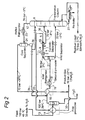
- FIG.1 and 2 similar reference numerals are used to identify similar components.
- FIG.1 and 2 each show a process scheme comprising a cyclonic expansion and separation device 1, which comprises swirl imparting vanes 2 mounted on a torpedo shaped central body 3, a nozzle 4 in which a swirling natural gas stream is accelerated to a transonic or supersonic velocity, a central primary fluid outlet 5 for discharging a methane enriched and methane depleted primary fluid fraction from the separation device 1 and an outer secondary fluid outlet 6 for discharging a condensables enriched & methane depleted secondary fluid fraction into a secondary discharge conduit 7.
- the secondary fluid fraction is fed via conduit 7 into a fluid fractionating column 8.
- the present invention provides a process scheme for H 2 S recovery based on a cyclonic expansion and separation device 1, which is sold by Twister B.V. under the trademark Twister (Twister is a trademark owned by Twister B.V.).
- Twister is a trademark owned by Twister B.V.
- the cooling inside the cyclonic separation device 1 is established by accelerating the feed stream to a substantially transonic or supersonic velocity. At supersonic condition the pressure has dropped to typically a factor 1/4 of the feed pressure, meanwhile the temperature drops to typically a factor 2/3 with respect to the feed temperature.
- the ratio of T-drop per unit P-drop for a given feed composition is determined with the isentropic efficiency of the expansion, which would be around the 85% for the cyclonic separation device.
- the isentropic efficiency expresses the frictional and heat losses occurring inside the device 1.
- the majority of the H 2 S components are liquefied in a fine droplet dispersion and separated in separation chamber in which the fluid mixture is swirled and separated into a liquid enriched outer fraction and a gas enriched central fraction.
- the expansion ratio (P/P feed ) is chosen such that at least the specified H 2 S fraction is condensed into liquid inside the separator.
- the flow inside the separation device 1 is split in a tubular separation chamber 9 into a H 2 S enriched flow ( ⁇ 30% of the total flow rate) and a H 2 S lean flow (approx. 70% of the total flow rate).
- the H 2 S lean main flow is decelerated in a diffuser 10, resulting in a rise of pressure and temperature.
- the P-rise and the accompanied T-rise in the diffuser 10 is determined with both the isentropic efficiency of the expansion and the isentropic efficiency of the recompression.
- the isentropic efficiency of expansion determines the remaining kinetic energy at the entrance of the diffuser, whereas the isentropic efficiency of recompression is determined with the losses inside the diffuser embodiment.
- the isentropic efficiency of recompression for a cyclonic separation device 1 is approx. 85%.
- the resulting outlet pressure of the H 2 S lean main flow is therefore lower than the feed pressure and about equal to the outlet pressure of the H 2 S enriched flow i.e. the column operating pressure.
- a cyclonic separator 1 based H 2 S scheme the optimisation of the H 2 S recovery is found in creating a deeper expansion in the cyclonic separator 1 (i.e. decrease of the ratio P/P feed ) at which the H 2 S liquid is separated.
- the concentrated H 2 S flow is fed to the fractionating column 8 thereby reducing its size and/or reducing the duty of a reflux refrigerator 23 which is arranged in the upper outlet conduit 12 of the fractionating column 8.
- This first heat exchanger 14 reduces the fluid temperature of the natural gas stream to well above the hydrate formation temperature ( ⁇ 29°C at 100 bar).
- liquefied H 2 S is injected via a first reflux conduit 25 of which a part may evaporate.
- the remaining H 2 S liquid will absorb the major part of the water vapour still present in the natural gas, thereby reducing the water content from ⁇ 1500 ppm/v (parts per million at a volumetric basis) at 100 bar and 29°C to ⁇ 900 ppm/v at 100 bar and 29 °C, thereby acting as a desiccant.
- the second heat exchanger 16 and an inlet refrigerator 18 arranged in the feed conduit 19 downstream of the second heat exchanger 16 will reduce the temperature fluid further to a T-range of -16 to -22°C though typically -18 °C.
- the liquids from the second heat exchanger 16, which contain predominantly H 2 S are separated in a inlet separation vessel 20 before the cooled natural gas stream 21 is fed to the cyclonic separator 1.
- the H 2 S rich liquid fraction discharged by the outer outlet 6 is fed via a conduit 22 to the fractionating column 8.
- the cooled natural gas stream 21 fed to the cyclonic separator 1 will contain about 20 mole% H 2 S at 100 bar and -18 °C.
- a stream of natural gas contaminated with hydrogen sulphide 13 is fed through a feed conduit 19 into a cyclonic separator 1 in which the feed gas is expanded with an expansion rate of factor 3 to 5 yielding a temperature of -70 °C at 33 bar resp. -90 °C at 20 bar.
- the H 2 S vapour fraction is ⁇ 4 - 7 mole%.
- a product gas stream discharged by a central outlet 5 of the cyclonic separator 1 can be established containing 5 - 8 mole% H 2 S.
- the H 2 S enriched secondary flow ( ⁇ 30% of total flow) leaving through the outer outlet 6 of the cyclonic separator 1 at about -30 °C is used for pre-cooling the feed gas in the second heat exchanger 16 before it is fed to the fractionating column 8.
- the gaseous components of the secondary H 2 S enriched fluid fraction discharged by the outer outlet 6 of the cyclonic separator 1(predominantly methane) will pass the lower trays of the fractionating column 8 together with the H 2 S vapour.
- the cooled reflux fluid discharged by the reflux refrigerator is separated in a reflux separation vessel 24 and a first major fraction of the liquids discharged from the bottom of the reflux refrigeration vessel are returned via a first reflux conduit 25 to the feed conduit 19 near the inlet of the second heat exchanger 16 and a minor part is refluxed through a second reflux conduit 26 to the fractionating column 8.
- the reflux partition can range from 70%/30% to 100%/0% though is typical 95%/5%.
- the cooling duty of the reflux refrigerator 23 is primarily determined by the required H 2 S vapour fraction of the produced gas leaving the reflux separation vessel 24 and secondarily determined by the required duty of the second heat exchanger 16 in order to obtain the required H 2 S vapour fraction of the produced gas stream leaving the cyclonic separator 1.
- the reboiler duty of the fractionating column 8 determines the remaining methane fraction in the liquid stream H 2 S, which is produced as bottom product 27.
- the dissolved methane fraction in the bottom product should be as low as possible.
- the reboiler duty also determines the H 2 S vapour stream leaving the top of the column and therefore the maximum amount of liquid H 2 S reflux for a given chiller duty.
- the reboiler temperature is chosen between the 40 and 80 °C though typically at 60 °C.
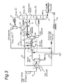
- FIG.2 depicts a flow scheme of a second embodiment of the method according to the invention, which is largely similar to the flow scheme shown in FIG. 1 and in which similar components are identified by similar reference numerals, but wherein the H 2 S enriched fluid fraction discharged from the outer outlet 6 of the cyclonic separator 1 is discharged by a conduit 30 directly into the fractionating column 8.
- FIG.3 depicts a flow scheme of a third embodiment of the method according to the invention, which is largely similar to the flow scheme shown in FIG. 2 and in which similar components are identified by similar reference numerals, but wherein the first reflux conduit 251 is connected in the feed conduit 19 between the outlet of the second heat exchanger 16 and the inlet of the refrigerator 18.
- a first H2S reflux from conduit 251 from the cold top of the fractionation column 8 is returned to the cooled feed stream from the second heat exchanger 16.
- This first H2S reflux which is relatively dry and relatively cold can be used beneficially for water absorption in the cold part of the feed gas.
- a reflux conduit 40 is arranged as conduit between the reboiler and the inlet of the second heat exchanger 16 for introduction of bottom product of a liquid H2S stream 27 that is collected in the reboiler, into the feed inlet at ⁇ 29°C.
- the bottom product of a liquid H2S stream 27 is returned as a second additional H2S reflux from the warm bottom of the fractionation column 8 to the feed inlet at ⁇ 29°C.
- This second H2S reflux which is relatively rich in water and relatively warm can be used beneficially for water absorption in the warm part of the feed gas.
- FIG.4 depicts a flow scheme of a fourth embodiment of the method according to the invention, which is largely similar to the flow scheme shown in FIG. 2 or FIG.3 and in which similar components are identified by similar reference numerals, but wherein the second precooler comprises the second heat exchanger 16, the refrigerator 18 and an in-line gas-liquid contactor 45.
- the in-line gas-liquid contactor 45 is arranged between the outlet of the second heat exchanger for receiving cooled feed gas at an gas stream inlet.
- An gas outlet of the contactor is connected to the feed inlet of the refrigerator 18.
- the first reflux conduit 252 is connected to a reflux inlet of the in-line gas-liquid contactor 45.
- the inline gas-liquid contactor 45 can be either operated co-currently or counter currently, though preferably counter currently.
- the in-line gas-liquid contactor is arranged for improving contact between the cooled feed gas from the second heat exchanger 16 and the liquid H2S reflux from the reflux separation vessel 24 so as to enhance water absorption by the reflux from the feed gas.
- An outlet for (H2S containing)liquid of the in-line gas-liquid contactor 45 is connected to a lower region (at relatively high temperature) of the fractionating column 8, to feed the H2S containing liquid of the in-line gas-liquid contactor 45 to the fractionating column.
- the outlet for liquid of the in-line gas-liquid contactor is connected to the liquid outlet line of the inlet separation vessel 20.
- the application of the in-line gas-liquid contactor 45 allows to reduce the water content of the feed gas by a more efficient interaction between the gas stream and the stream of liquid reflux.
- the third reflux conduit 40 is arranged as conduit between the reboiler and the inlet of the second heat exchanger 16 to return bottom product 27 that is collected in the reboiler into the feed inlet at ⁇ 29°C.
- in-line gas-liquid contactors can be extended by a replacement of the fractionation column itself by one or more in-line gas-liquid contactors.
- a further in-line gas-liquid contactor may be used in any of the above process schemes for introducing a H2S reflux stream as water absorbing fluid at some point in the feed gas stream.
Landscapes
- Chemical & Material Sciences (AREA)
- Engineering & Computer Science (AREA)
- Oil, Petroleum & Natural Gas (AREA)
- Chemical Kinetics & Catalysis (AREA)
- General Chemical & Material Sciences (AREA)
- Organic Chemistry (AREA)
- Analytical Chemistry (AREA)
- Thermal Sciences (AREA)
- Mechanical Engineering (AREA)
- General Engineering & Computer Science (AREA)
- Physics & Mathematics (AREA)
- Health & Medical Sciences (AREA)
- Biomedical Technology (AREA)
- Environmental & Geological Engineering (AREA)
- Separation By Low-Temperature Treatments (AREA)
- Cyclones (AREA)
- Separating Particles In Gases By Inertia (AREA)
Abstract
Claims (13)
- Procédé d'élimination du sulfure d'hydrogène d'un courant de gaz naturel comprenant du méthane et du sulfure d'hydrogène, le procédé comprenant les étapes consistant à :- refroidir le courant de gaz naturel dans un ensemble échangeur de chaleur ;- délivrer au moins une partie du courant de gaz naturel refroidi à travers un conduit d'alimentation dans un dispositif de dilatation et de séparation cyclonique dans lequel le courant de gaz naturel refroidi est dilaté dans une buse et ainsi davantage refroidi à une température et à une pression en dessous du point de rosée du sulfure d'hydrogène et est séparé en amenant le courant de gaz naturel refroidi à tourbillonner dans une chambre de séparation tubulaire, amenant ainsi des forces centrifuges à séparer le courant de gaz naturel refroidi en une fraction de fluide de basse densité refroidie, qui est appauvrie en sulfure d'hydrogène et enrichie en méthane, et une fraction de fluide de haute densité refroidie qui est enrichie en sulfure d'hydrogène et appauvrie en méthane ;- délivrer la fraction de fluide de basse densité refroidie à un conduit de gaz produit qui est raccordé à l'ensemble échangeur de chaleur permettant de refroidir le courant de gaz naturel délivré au dispositif de dilatation et de séparation cyclonique ; et- délivrer la fraction de fluide de haute densité refroidie à une colonne de fractionnement pour séparation supplémentaire, et où la colonne de fractionnement est configurée pour séparer la fraction de fluide de haute densité évacuée par le dispositif de dilatation et de séparation cyclonique en une fraction inférieure enrichie en sulfure d'hydrogène et appauvrie en méthane et une fraction supérieure appauvrie en sulfure d'hydrogène et enrichie en méthane,caractérisé en ce que
la fraction supérieure appauvrie en sulfure d'hydrogène et enrichie en méthane est évacuée de la partie supérieure de la colonne de fractionnement dans un conduit de reflux dans lequel un réfrigérateur de reflux est agencé et qui évacue la fraction supérieure refroidie dans une cuve de séparation par reflux dans laquelle la fraction supérieure refroidie est séparée en :a) une fraction appauvrie en sulfure d'hydrogène et enrichie en méthane sensiblement gazeuse refroidie, qui est mélangée avec la fraction de fluide appauvrie en sulfure d'hydrogène et enrichie en méthane évacuée par le dispositif de dilatation et de séparation cyclonique ; etb) une fraction de fluide sensiblement liquide enrichie en sulfure d'hydrogène et appauvrie en méthane refroidie, qui est remise à circuler dans le conduit d' alimentation. - Procédé selon la revendication 1, dans lequel le conduit d'alimentation comprend une cuve de séparation d'eau et l'ensemble échangeur de chaleur comprend un réfrigérateur d'entrée de sorte que le courant de gaz naturel délivré au dispositif de dilatation et de séparation cyclonique a une teneur en eau réduite et une température comprise entre 5 et -25 degrés Celsius.
- Procédé selon la revendication 1, dans lequel la fraction de fluide sensiblement liquide enrichie en sulfure d'hydrogène et appauvrie en méthane refroidie, qui est remise à circuler dans le conduit d'alimentation, fonctionne comme un dessicant du courant de gaz naturel refroidi circulant à travers le conduit d' alimentation.
- Procédé selon la revendication 1, dans lequel la colonne de fractionnement est agencée pour produire un courant de H2S liquide de produit inférieur qui est remis à circuler en tant que reflux de H2S vers une entrée de l'ensemble échangeur de chaleur.
- Procédé selon la revendication 2, dans lequel l'ensemble échangeur de chaleur comprend en outre :- un premier échangeur de chaleur dans lequel le courant de gaz naturel est refroidi par la fraction de fluide de basse densité refroidie circulant à travers le conduit de gaz produit à une température en dessous du point de rosée dudit courant de gaz naturel, premier échangeur de chaleur à partir duquel le gaz naturel refroidi entre dans la cuve de séparation d'eau ; et- un second échangeur de chaleur dans lequel le courant de gaz naturel séparé de son eau évacué par la cuve de séparation d'eau est refroidi par la fraction appauvrie en sulfure d'hydrogène et enrichie en méthane sensiblement gazeuse refroidie évacuée par la cuve de séparation par reflux.
- Procédé selon la revendication 5, dans lequel la fraction de fluide sensiblement liquide enrichie en sulfure d'hydrogène et appauvrie en méthane refroidie est introduite dans le conduit d'alimentation à une sortie du second échangeur de chaleur.
- Procédé selon la revendication 5, dans lequel le conduit d'alimentation comprend en outre une cuve de séparation gaz-liquide, qui est agencée entre le réfrigérateur d'entrée et une entrée du dispositif de dilatation et de séparation cyclonique, cuve dans laquelle le courant de gaz naturel refroidi est séparé en une fraction supérieure enrichie en méthane et appauvrie en sulfure d'hydrogène qui est délivrée au dispositif de dilatation et de séparation cyclonique et une fraction inférieure enrichie en sulfure d'hydrogène et appauvrie en méthane, qui est délivrée dans la colonne de fractionnement.
- Procédé selon la revendication 1, dans lequel l'ensemble échangeur de chaleur comprend en outre un contacteur gaz-liquide en ligne, où le contacteur gaz-liquide en ligne est agencé pour recevoir un courant de gaz naturel refroidi de l'ensemble échangeur de chaleur à une entrée de courant de gaz et la fraction de fluide sensiblement liquide enrichie en sulfure d'hydrogène et appauvrie en méthane refroidie provenant de la cuve de séparation par reflux à une entrée de reflux ; le contacteur gaz-liquide en ligne étant agencé pour mettre en contact le courant de gaz et le courant de la fraction de fluide sensiblement liquide pour permettre une absorption d'eau à partir du courant de gaz par le courant de la fraction de fluide sensiblement liquide.
- Procédé selon la revendication 1, dans lequel le dispositif de dilatation et de séparation cyclonique comprend :a) un ensemble d'aubes communiquant un tourbillonnement permettant d'imposer un mouvement de tourbillonnement au courant de gaz naturel, lesquelles aubes sont agencées en amont d'une buse dans laquelle le courant de gaz naturel est accéléré à une vitesse sensiblement supersonique et dilaté et ainsi davantage refroidi de telle sorte que des forces centrifuges séparent le courant de fluide de tourbillonnement dans la chambre de séparation tubulaire, qui est agencée en aval de la buse, en des fractions de fluide de basse et haute densité.
- Procédé selon la revendication 9, dans lequel le dispositif de dilatation et de séparation cyclonique comprend un ensemble d'aubes communiquant un tourbillonnement qui font saillie dans au moins une direction partiellement radiale à partir d'un corps central en forme de torpille en amont de la buse, lequel corps a un diamètre externe plus grand que le diamètre interne de la buse.
- Procédé selon la revendication 10, dans lequel le corps en forme de torpille, l'ensemble d'aubes communiquant un tourbillonnement et la buse sont configurés de telle sorte que le rendement isentropique de la dilatation dans la buse est d'au moins 80%.
- Système d'élimination du sulfure d'hydrogène d'un courant de gaz naturel qui contient du méthane et du sulfure d'hydrogène, le système comprenant :- un ensemble échangeur de chaleur permettant de refroidir le courant de gaz naturel ;- un dispositif de dilatation et de séparation cyclonique qui est raccordé à une sortie de l'échangeur de chaleur via un conduit d'alimentation, lequel dispositif comprend une buse agencée pour dilater et ainsi refroidir davantage le courant de gaz naturel refroidi à une température et à une pression en dessous du point de rosée du sulfure d'hydrogène et une chambre de séparation tubulaire agencée pour amener le courant de gaz naturel refroidi à tourbillonner, amenant ainsi des forces centrifuges à séparer le courant de gaz naturel refroidi en une fraction de fluide de basse densité refroidie, qui est appauvrie en sulfure d'hydrogène et enrichie en méthane, et une fraction de fluide de haute densité refroidie, qui est enrichie en sulfure d'hydrogène et appauvrie en méthane ;- un conduit de gaz produit agencé pour être alimenté avec la fraction de basse densité refroidie, conduit de gaz produit qui est raccordé à l'échangeur de chaleur pour refroidir le courant de gaz naturel délivré au dispositif de dilatation et de séparation cyclonique ; et- une colonne de fractionnement agencée pour être alimentée avec la fraction de fluide de haute densité refroidie pour une séparation supplémentaire, etoù la colonne de fractionnement est configurée pour séparer la fraction de fluide de haute densité évacuée par le dispositif de dilatation et de séparation cyclonique en une fraction inférieure enrichie en sulfure d'hydrogène et appauvrie en méthane et une fraction supérieure appauvrie en sulfure d'hydrogène et enrichie en méthane, caractérisé en ce que
la partie supérieure de la colonne de fractionnement est agencée pour évacuer la fraction supérieure appauvrie en sulfure d'hydrogène et enrichie en méthane dans un conduit de reflux dans lequel un réfrigérateur de reflux est agencé pour évacuer la fraction supérieure refroidie dans une cuve de séparation par reflux qui est agencée pour séparer la fraction supérieure refroidie en :a) une fraction appauvrie en sulfure d'hydrogène et enrichie en méthane sensiblement gazeuse refroidie, qui est agencée pour être mélangée avec la fraction de fluide appauvrie en sulfure d'hydrogène et enrichie en méthane évacuée par le dispositif de dilatation et de séparation cyclonique ; etb) une fraction de fluide sensiblement liquide enrichie en sulfure d'hydrogène et appauvrie en méthane refroidie, qui est agencée pour être remise à circuler dans le conduit d'alimentation. - Système selon la revendication 12,
dans lequel l'ensemble échangeur de chaleur comprend en outre un contacteur gaz-liquide en ligne, dans lequel le contacteur gaz-liquide en ligne est agencé à la sortie de l'ensemble échangeur de chaleur pour recevoir à une entrée de courant de gaz un courant de gaz d'alimentation refroidi de l'ensemble échangeur de chaleur et à une entrée de reflux la fraction de fluide sensiblement liquide enrichie en sulfure d'hydrogène et appauvrie en méthane refroidie provenant de la cuve de séparation par reflux ; le contacteur gaz-liquide en ligne étant agencé pour mettre en contact le courant de gaz et le courant de la fraction de fluide sensiblement liquide pour permettre une absorption d'eau à partir du courant de gaz par le courant de la fraction de fluide sensiblement liquide.
Priority Applications (1)
| Application Number | Priority Date | Filing Date | Title |
|---|---|---|---|
| EP08766847A EP2160452B1 (fr) | 2007-06-27 | 2008-06-27 | Procédé et système permettant d'éliminer le h2s d'un flux de gaz naturel |
Applications Claiming Priority (3)
| Application Number | Priority Date | Filing Date | Title |
|---|---|---|---|
| EP07111145 | 2007-06-27 | ||
| EP08766847A EP2160452B1 (fr) | 2007-06-27 | 2008-06-27 | Procédé et système permettant d'éliminer le h2s d'un flux de gaz naturel |
| PCT/NL2008/050424 WO2009002174A2 (fr) | 2007-06-27 | 2008-06-27 | Procédé et système permettant d'éliminer le h2s d'un flux de gaz naturel |
Publications (2)
| Publication Number | Publication Date |
|---|---|
| EP2160452A2 EP2160452A2 (fr) | 2010-03-10 |
| EP2160452B1 true EP2160452B1 (fr) | 2011-08-17 |
Family
ID=39302104
Family Applications (1)
| Application Number | Title | Priority Date | Filing Date |
|---|---|---|---|
| EP08766847A Not-in-force EP2160452B1 (fr) | 2007-06-27 | 2008-06-27 | Procédé et système permettant d'éliminer le h2s d'un flux de gaz naturel |
Country Status (13)
| Country | Link |
|---|---|
| US (1) | US9500404B2 (fr) |
| EP (1) | EP2160452B1 (fr) |
| CN (1) | CN101778931B (fr) |
| AR (1) | AR067341A1 (fr) |
| AT (1) | ATE520761T1 (fr) |
| CA (1) | CA2691743C (fr) |
| EA (1) | EA015953B1 (fr) |
| EG (1) | EG26358A (fr) |
| MY (1) | MY147349A (fr) |
| PE (1) | PE20090523A1 (fr) |
| RU (1) | RU2462295C2 (fr) |
| TW (1) | TW200912228A (fr) |
| WO (1) | WO2009002174A2 (fr) |
Families Citing this family (33)
| Publication number | Priority date | Publication date | Assignee | Title |
|---|---|---|---|---|
| WO2010014008A1 (fr) * | 2008-07-30 | 2010-02-04 | Twister B.V. | Système et procédé d'élimination du sulfure d'hydrogène d'un flux de gaz naturel |
| NL2002691C2 (en) * | 2009-03-31 | 2010-10-04 | Romico Hold A V V | Method for separating a medium mixture into fractions. |
| AU2009344225B2 (en) | 2009-04-07 | 2013-04-04 | Twister B.V. | Separation system comprising a swirl valve |
| PL2365852T3 (pl) * | 2009-07-13 | 2022-10-24 | Dexpro Corporation | Sposób usuwania składników ulegających kondensacji z płynu |
| DE102009037460A1 (de) * | 2009-08-13 | 2011-02-17 | Siemens Aktiengesellschaft | Abscheiden von Schwefelwasserstoff |
| CA2800822A1 (fr) | 2010-06-01 | 2011-12-08 | Shell Internationale Research Maatschappij B.V. | Separation de gaz produits par combustion |
| WO2011153151A1 (fr) | 2010-06-01 | 2011-12-08 | Shell Oil Company | Centrale électrique à faible émission |
| US8858680B2 (en) | 2010-06-01 | 2014-10-14 | Shell Oil Company | Separation of oxygen containing gases |
| US8858679B2 (en) | 2010-06-01 | 2014-10-14 | Shell Oil Company | Separation of industrial gases |
| AU2011296633B2 (en) * | 2010-09-03 | 2016-07-14 | Twister B.V. | Refining system and method for refining a feed gas stream |
| CA2818326A1 (fr) * | 2010-10-20 | 2012-04-26 | Kirtikumar Natubhai Patel | Procede de separation et de recuperation d'ethane et d'hydrocarbures plus lourds a partir de gnl |
| CN103084285B (zh) * | 2011-11-03 | 2015-06-17 | 西安长庆科技工程有限责任公司 | 一种天然气的气液分离装置及方法 |
| CA2763081C (fr) * | 2011-12-20 | 2019-08-13 | Jose Lourenco | Methode de production de gaz naturel liquefie (gnl) dans les usines de recuperation de liquides de gaz naturels (lgn) intermediaires. |
| RU2493501C1 (ru) * | 2012-03-02 | 2013-09-20 | Олег Савельевич Кочетов | Приточно-вытяжная установка с утилизацией тепла |
| CA2790961C (fr) | 2012-05-11 | 2019-09-03 | Jose Lourenco | Une methode de recuperation de gpl et de condensats des flux de gaz de carburant de raffineries. |
| CA2798057C (fr) | 2012-12-04 | 2019-11-26 | Mackenzie Millar | Une methode produire du gnl dans les stations de detente de pression de gaz dans les systemes de gazoduc de gaz naturel |
| CN103111173B (zh) * | 2013-01-21 | 2015-09-02 | 江汉大学 | 一种烟气净化系统及其方法 |
| CA2813260C (fr) | 2013-04-15 | 2021-07-06 | Mackenzie Millar | Procede de production de gaz naturel liquefie |
| AR096132A1 (es) | 2013-05-09 | 2015-12-09 | Exxonmobil Upstream Res Co | Separar dióxido de carbono y sulfuro de hidrógeno de un flujo de gas natural con sistemas de co-corriente en contacto |
| ES2668535T3 (es) * | 2014-03-07 | 2018-05-18 | Conocophillips Company | Sistema de intercambiador de calor con separador en línea mono-ciclón |
| CA2958091C (fr) | 2014-08-15 | 2021-05-18 | 1304338 Alberta Ltd. | Procede d'elimination de dioxyde de carbone pendant la production de gaz naturel liquide a partir de gaz naturel dans des stations d'abaissement de pression de gaz |
| JP6573675B2 (ja) | 2015-01-09 | 2019-09-11 | エクソンモービル アップストリーム リサーチ カンパニー | 複式並流接触器を用いた流体流からの不純物の分離 |
| MX2017008682A (es) | 2015-02-17 | 2017-10-11 | Exxonmobil Upstream Res Co | Caracteristicas de superficie interiores para contactores de co-corriente. |
| US10391442B2 (en) | 2015-03-13 | 2019-08-27 | Exxonmobil Upstream Research Company | Coalescer for co-current contractors |
| WO2017045055A1 (fr) | 2015-09-16 | 2017-03-23 | 1304342 Alberta Ltd. | Procédé de préparation de gaz naturel au niveau de stations de réduction de la pression d'un gaz pour produire du gaz naturel liquide (gnl) |
| CN108291766B (zh) * | 2015-12-03 | 2020-07-07 | 国际壳牌研究有限公司 | 液化co2污染的含烃气流的方法 |
| KR101784996B1 (ko) | 2016-02-02 | 2017-11-06 | 한국기계연구원 | 황화수소 제거 장치 |
| BR112019026289B1 (pt) | 2017-06-15 | 2023-10-10 | ExxonMobil Technology and Engineering Company | Sistema de fracionamento com o uso de sistemas de contato de cocorrente compactos e método para remover hidrocarbonetos pesados em corrente de gás |
| CA3067338C (fr) | 2017-06-15 | 2023-03-07 | Exxonmobil Upstream Research Company | Systeme de fractionnement utilisant des systemes groupeurs compacts de mise en contact de co-courants |
| SG11201910961WA (en) | 2017-06-20 | 2020-01-30 | Exxonmobil Upstream Res Co | Compact contacting systems and methods for scavenging sulfur-containing compounds |
| WO2019040306A1 (fr) | 2017-08-21 | 2019-02-28 | Exxonmobil Upstream Research Company | Intégration de solvant froid et d'élimination de gaz acide |
| CN112263894A (zh) * | 2020-11-26 | 2021-01-26 | 西南石油大学 | 一种针对含硫气体的离子液体脱硫方法及设备 |
| CN114682050B (zh) * | 2020-12-30 | 2023-05-05 | 中国石油化工股份有限公司 | 烟气处理装置及方法 |
Family Cites Families (13)
| Publication number | Priority date | Publication date | Assignee | Title |
|---|---|---|---|---|
| DE2924162A1 (de) * | 1979-06-15 | 1980-12-18 | Linde Ag | Verfahren zum selektiven auswaschen von schwefelverbindungen aus feuchten gasgemischen |
| SU1366821A1 (ru) * | 1984-06-28 | 1988-01-15 | Специализированное Управление "Узоргэнергогаз" | Способ очистки природного газа от кислых компонентов |
| IT1256062B (it) * | 1992-11-20 | 1995-11-23 | Snam Progetti | Procedimento per l'ottenimento di correnti di metanolo, etanolo, n-propanolo,isobutanolo,utilizzabili soprattutto nella preparazione diprodotti alto ottanici, da miscele contenenti detti alcoli con acqua ed altri composti bassobollenti e altobollenti |
| ATE260454T1 (de) * | 1998-10-16 | 2004-03-15 | Translang Technologies Ltd | Verfahren und vorrichtung zur verflüssigung eines gases |
| FR2814378B1 (fr) * | 2000-09-26 | 2002-10-31 | Inst Francais Du Petrole | Procede de pretraitement d'un gaz naturel contenant des gaz acides |
| US20020189443A1 (en) * | 2001-06-19 | 2002-12-19 | Mcguire Patrick L. | Method of removing carbon dioxide or hydrogen sulfide from a gas |
| JO2366B1 (en) * | 2001-09-28 | 2006-12-12 | شل انترناشونال ريسيرتش ماتشابيج بي في | Whirlpool inhibitor with swirling material at the entrance |
| RU2218974C1 (ru) * | 2002-07-05 | 2003-12-20 | Фахриев Ахматфаиль Магсумович | Способ подготовки сероводород- и меркаптансодержащей нефти |
| FR2848121B1 (fr) * | 2002-12-04 | 2005-01-28 | Inst Francais Du Petrole | Procede de traitement d'un gaz naturel acide |
| DE10313438A1 (de) * | 2003-03-26 | 2004-11-04 | Uhde Gmbh | Verfahren zur selektiven Entfernung von Schwefelwasserstoff und CO2 aus Rohgas |
| RU2272973C1 (ru) | 2004-09-24 | 2006-03-27 | Салават Зайнетдинович Имаев | Способ низкотемпературной сепарации газа (варианты) |
| WO2006087332A1 (fr) * | 2005-02-17 | 2006-08-24 | Shell Internationale Research Maatschappij B.V. | Procede d'evacuation de composants gazeux contaminants d'un flux de gaz naturel |
| NZ556495A (en) * | 2005-02-24 | 2009-09-25 | Twister Bv | Method and system for cooling a natural gas stream and separating the cooled stream into various fractions |
-
2008
- 2008-06-26 TW TW097123870A patent/TW200912228A/zh unknown
- 2008-06-27 AR ARP080102785A patent/AR067341A1/es unknown
- 2008-06-27 AT AT08766847T patent/ATE520761T1/de not_active IP Right Cessation
- 2008-06-27 RU RU2010102536/05A patent/RU2462295C2/ru active
- 2008-06-27 PE PE2008001108A patent/PE20090523A1/es not_active Application Discontinuation
- 2008-06-27 WO PCT/NL2008/050424 patent/WO2009002174A2/fr active Application Filing
- 2008-06-27 CA CA2691743A patent/CA2691743C/fr active Active
- 2008-06-27 CN CN2008800225154A patent/CN101778931B/zh not_active Expired - Fee Related
- 2008-06-27 EP EP08766847A patent/EP2160452B1/fr not_active Not-in-force
- 2008-06-27 MY MYPI20095615A patent/MY147349A/en unknown
- 2008-06-27 EA EA201000072A patent/EA015953B1/ru not_active IP Right Cessation
- 2008-06-27 US US12/670,333 patent/US9500404B2/en active Active
-
2009
- 2009-12-27 EG EG2009121916A patent/EG26358A/en active
Also Published As
| Publication number | Publication date |
|---|---|
| CN101778931A (zh) | 2010-07-14 |
| RU2010102536A (ru) | 2011-08-10 |
| EA201000072A1 (ru) | 2010-08-30 |
| CA2691743C (fr) | 2017-06-20 |
| EA015953B1 (ru) | 2011-12-30 |
| EG26358A (en) | 2013-08-26 |
| US9500404B2 (en) | 2016-11-22 |
| PE20090523A1 (es) | 2009-05-24 |
| ATE520761T1 (de) | 2011-09-15 |
| MY147349A (en) | 2012-11-30 |
| TW200912228A (en) | 2009-03-16 |
| EP2160452A2 (fr) | 2010-03-10 |
| CN101778931B (zh) | 2013-03-27 |
| AR067341A1 (es) | 2009-10-07 |
| RU2462295C2 (ru) | 2012-09-27 |
| WO2009002174A2 (fr) | 2008-12-31 |
| WO2009002174A3 (fr) | 2009-02-19 |
| US20110036122A1 (en) | 2011-02-17 |
| CA2691743A1 (fr) | 2008-12-31 |
Similar Documents
| Publication | Publication Date | Title |
|---|---|---|
| EP2160452B1 (fr) | Procédé et système permettant d'éliminer le h2s d'un flux de gaz naturel | |
| JP5032342B2 (ja) | 天然ガス流を冷却し、冷却流を各種フラクションに分離する方法及びシステム | |
| CA2810265C (fr) | Systeme de raffinage et procede de raffinage d'un courant de gaz d'alimentation | |
| JP4571934B2 (ja) | 炭化水素ガス処理 | |
| US4251249A (en) | Low temperature process for separating propane and heavier hydrocarbons from a natural gas stream | |
| US20020189443A1 (en) | Method of removing carbon dioxide or hydrogen sulfide from a gas | |
| AU2008213739B2 (en) | Process and apparatus for depleting carbon dioxide content in a natural gas feedstream containing ethane and C3+ hydrocarbons | |
| AU2009272889A1 (en) | Two stage process for producing purified gas | |
| ES2400810T3 (es) | Retirada de líquidos del gas natural a partir de una corriente gaseosa de gas natural | |
| AU2007319977A1 (en) | Configurations and methods for gas condensate separation from high-pressure hydrocarbon mixtures | |
| EP3479037B1 (fr) | Système et procédé de production de gaz naturel liquéfié | |
| WO2010040735A2 (fr) | Procédés de traitement d’un courant d’hydrocarbures et appareil associé | |
| Betting et al. | Method and system for removing H 2 S from a natural gas stream | |
| US20120324941A1 (en) | Process for producing a contaminant-depleted hydrocarbon gas stream with improved hydrocarbon recovery | |
| AU2013204700A1 (en) | Multistage cyclonic fluid separator | |
| EP2540371A1 (fr) | Procédé d'élimination d'hydrocarbures aromatiques provenant d'un flux gazeux riche en hydrocarbures aliphatiques |
Legal Events
| Date | Code | Title | Description |
|---|---|---|---|
| PUAI | Public reference made under article 153(3) epc to a published international application that has entered the european phase |
Free format text: ORIGINAL CODE: 0009012 |
|
| 17P | Request for examination filed |
Effective date: 20091223 |
|
| AK | Designated contracting states |
Kind code of ref document: A2 Designated state(s): AT BE BG CH CY CZ DE DK EE ES FI FR GB GR HR HU IE IS IT LI LT LU LV MC MT NL NO PL PT RO SE SI SK TR |
|
| AX | Request for extension of the european patent |
Extension state: AL BA MK RS |
|
| 17Q | First examination report despatched |
Effective date: 20100526 |
|
| GRAP | Despatch of communication of intention to grant a patent |
Free format text: ORIGINAL CODE: EPIDOSNIGR1 |
|
| DAX | Request for extension of the european patent (deleted) | ||
| GRAS | Grant fee paid |
Free format text: ORIGINAL CODE: EPIDOSNIGR3 |
|
| GRAA | (expected) grant |
Free format text: ORIGINAL CODE: 0009210 |
|
| AK | Designated contracting states |
Kind code of ref document: B1 Designated state(s): AT BE BG CH CY CZ DE DK EE ES FI FR GB GR HR HU IE IS IT LI LT LU LV MC MT NL NO PL PT RO SE SI SK TR |
|
| REG | Reference to a national code |
Ref country code: GB Ref legal event code: FG4D |
|
| REG | Reference to a national code |
Ref country code: CH Ref legal event code: EP |
|
| REG | Reference to a national code |
Ref country code: IE Ref legal event code: FG4D |
|
| REG | Reference to a national code |
Ref country code: DE Ref legal event code: R096 Ref document number: 602008008973 Country of ref document: DE Effective date: 20111013 |
|
| REG | Reference to a national code |
Ref country code: NL Ref legal event code: VDEP Effective date: 20110817 |
|
| LTIE | Lt: invalidation of european patent or patent extension |
Effective date: 20110817 |
|
| PG25 | Lapsed in a contracting state [announced via postgrant information from national office to epo] |
Ref country code: SE Free format text: LAPSE BECAUSE OF FAILURE TO SUBMIT A TRANSLATION OF THE DESCRIPTION OR TO PAY THE FEE WITHIN THE PRESCRIBED TIME-LIMIT Effective date: 20110817 Ref country code: PT Free format text: LAPSE BECAUSE OF FAILURE TO SUBMIT A TRANSLATION OF THE DESCRIPTION OR TO PAY THE FEE WITHIN THE PRESCRIBED TIME-LIMIT Effective date: 20111219 Ref country code: FI Free format text: LAPSE BECAUSE OF FAILURE TO SUBMIT A TRANSLATION OF THE DESCRIPTION OR TO PAY THE FEE WITHIN THE PRESCRIBED TIME-LIMIT Effective date: 20110817 Ref country code: NO Free format text: LAPSE BECAUSE OF FAILURE TO SUBMIT A TRANSLATION OF THE DESCRIPTION OR TO PAY THE FEE WITHIN THE PRESCRIBED TIME-LIMIT Effective date: 20111117 Ref country code: IS Free format text: LAPSE BECAUSE OF FAILURE TO SUBMIT A TRANSLATION OF THE DESCRIPTION OR TO PAY THE FEE WITHIN THE PRESCRIBED TIME-LIMIT Effective date: 20111217 Ref country code: NL Free format text: LAPSE BECAUSE OF FAILURE TO SUBMIT A TRANSLATION OF THE DESCRIPTION OR TO PAY THE FEE WITHIN THE PRESCRIBED TIME-LIMIT Effective date: 20110817 Ref country code: LT Free format text: LAPSE BECAUSE OF FAILURE TO SUBMIT A TRANSLATION OF THE DESCRIPTION OR TO PAY THE FEE WITHIN THE PRESCRIBED TIME-LIMIT Effective date: 20110817 |
|
| REG | Reference to a national code |
Ref country code: AT Ref legal event code: MK05 Ref document number: 520761 Country of ref document: AT Kind code of ref document: T Effective date: 20110817 |
|
| PG25 | Lapsed in a contracting state [announced via postgrant information from national office to epo] |
Ref country code: SI Free format text: LAPSE BECAUSE OF FAILURE TO SUBMIT A TRANSLATION OF THE DESCRIPTION OR TO PAY THE FEE WITHIN THE PRESCRIBED TIME-LIMIT Effective date: 20110817 Ref country code: AT Free format text: LAPSE BECAUSE OF FAILURE TO SUBMIT A TRANSLATION OF THE DESCRIPTION OR TO PAY THE FEE WITHIN THE PRESCRIBED TIME-LIMIT Effective date: 20110817 Ref country code: CY Free format text: LAPSE BECAUSE OF FAILURE TO SUBMIT A TRANSLATION OF THE DESCRIPTION OR TO PAY THE FEE WITHIN THE PRESCRIBED TIME-LIMIT Effective date: 20110817 Ref country code: PL Free format text: LAPSE BECAUSE OF FAILURE TO SUBMIT A TRANSLATION OF THE DESCRIPTION OR TO PAY THE FEE WITHIN THE PRESCRIBED TIME-LIMIT Effective date: 20110817 Ref country code: LV Free format text: LAPSE BECAUSE OF FAILURE TO SUBMIT A TRANSLATION OF THE DESCRIPTION OR TO PAY THE FEE WITHIN THE PRESCRIBED TIME-LIMIT Effective date: 20110817 Ref country code: GR Free format text: LAPSE BECAUSE OF FAILURE TO SUBMIT A TRANSLATION OF THE DESCRIPTION OR TO PAY THE FEE WITHIN THE PRESCRIBED TIME-LIMIT Effective date: 20111118 |
|
| PG25 | Lapsed in a contracting state [announced via postgrant information from national office to epo] |
Ref country code: BE Free format text: LAPSE BECAUSE OF FAILURE TO SUBMIT A TRANSLATION OF THE DESCRIPTION OR TO PAY THE FEE WITHIN THE PRESCRIBED TIME-LIMIT Effective date: 20110817 |
|
| PG25 | Lapsed in a contracting state [announced via postgrant information from national office to epo] |
Ref country code: SK Free format text: LAPSE BECAUSE OF FAILURE TO SUBMIT A TRANSLATION OF THE DESCRIPTION OR TO PAY THE FEE WITHIN THE PRESCRIBED TIME-LIMIT Effective date: 20110817 Ref country code: CZ Free format text: LAPSE BECAUSE OF FAILURE TO SUBMIT A TRANSLATION OF THE DESCRIPTION OR TO PAY THE FEE WITHIN THE PRESCRIBED TIME-LIMIT Effective date: 20110817 |
|
| PG25 | Lapsed in a contracting state [announced via postgrant information from national office to epo] |
Ref country code: EE Free format text: LAPSE BECAUSE OF FAILURE TO SUBMIT A TRANSLATION OF THE DESCRIPTION OR TO PAY THE FEE WITHIN THE PRESCRIBED TIME-LIMIT Effective date: 20110817 Ref country code: IT Free format text: LAPSE BECAUSE OF FAILURE TO SUBMIT A TRANSLATION OF THE DESCRIPTION OR TO PAY THE FEE WITHIN THE PRESCRIBED TIME-LIMIT Effective date: 20110817 Ref country code: RO Free format text: LAPSE BECAUSE OF FAILURE TO SUBMIT A TRANSLATION OF THE DESCRIPTION OR TO PAY THE FEE WITHIN THE PRESCRIBED TIME-LIMIT Effective date: 20110817 |
|
| PLBE | No opposition filed within time limit |
Free format text: ORIGINAL CODE: 0009261 |
|
| STAA | Information on the status of an ep patent application or granted ep patent |
Free format text: STATUS: NO OPPOSITION FILED WITHIN TIME LIMIT |
|
| PG25 | Lapsed in a contracting state [announced via postgrant information from national office to epo] |
Ref country code: DK Free format text: LAPSE BECAUSE OF FAILURE TO SUBMIT A TRANSLATION OF THE DESCRIPTION OR TO PAY THE FEE WITHIN THE PRESCRIBED TIME-LIMIT Effective date: 20110817 |
|
| 26N | No opposition filed |
Effective date: 20120521 |
|
| PG25 | Lapsed in a contracting state [announced via postgrant information from national office to epo] |
Ref country code: HR Free format text: LAPSE BECAUSE OF FAILURE TO SUBMIT A TRANSLATION OF THE DESCRIPTION OR TO PAY THE FEE WITHIN THE PRESCRIBED TIME-LIMIT Effective date: 20120328 |
|
| REG | Reference to a national code |
Ref country code: DE Ref legal event code: R097 Ref document number: 602008008973 Country of ref document: DE Effective date: 20120521 |
|
| PG25 | Lapsed in a contracting state [announced via postgrant information from national office to epo] |
Ref country code: MC Free format text: LAPSE BECAUSE OF NON-PAYMENT OF DUE FEES Effective date: 20120630 |
|
| REG | Reference to a national code |
Ref country code: CH Ref legal event code: PL |
|
| REG | Reference to a national code |
Ref country code: CH Ref legal event code: PL |
|
| GBPC | Gb: european patent ceased through non-payment of renewal fee |
Effective date: 20120627 |
|
| REG | Reference to a national code |
Ref country code: IE Ref legal event code: MM4A |
|
| REG | Reference to a national code |
Ref country code: DE Ref legal event code: R119 Ref document number: 602008008973 Country of ref document: DE Effective date: 20130101 |
|
| PG25 | Lapsed in a contracting state [announced via postgrant information from national office to epo] |
Ref country code: IE Free format text: LAPSE BECAUSE OF NON-PAYMENT OF DUE FEES Effective date: 20120627 Ref country code: CH Free format text: LAPSE BECAUSE OF NON-PAYMENT OF DUE FEES Effective date: 20120630 Ref country code: LI Free format text: LAPSE BECAUSE OF NON-PAYMENT OF DUE FEES Effective date: 20120630 Ref country code: GB Free format text: LAPSE BECAUSE OF NON-PAYMENT OF DUE FEES Effective date: 20120627 Ref country code: DE Free format text: LAPSE BECAUSE OF NON-PAYMENT OF DUE FEES Effective date: 20130101 Ref country code: ES Free format text: LAPSE BECAUSE OF FAILURE TO SUBMIT A TRANSLATION OF THE DESCRIPTION OR TO PAY THE FEE WITHIN THE PRESCRIBED TIME-LIMIT Effective date: 20111128 |
|
| PG25 | Lapsed in a contracting state [announced via postgrant information from national office to epo] |
Ref country code: BG Free format text: LAPSE BECAUSE OF FAILURE TO SUBMIT A TRANSLATION OF THE DESCRIPTION OR TO PAY THE FEE WITHIN THE PRESCRIBED TIME-LIMIT Effective date: 20111117 |
|
| PG25 | Lapsed in a contracting state [announced via postgrant information from national office to epo] |
Ref country code: MT Free format text: LAPSE BECAUSE OF FAILURE TO SUBMIT A TRANSLATION OF THE DESCRIPTION OR TO PAY THE FEE WITHIN THE PRESCRIBED TIME-LIMIT Effective date: 20110817 |
|
| PG25 | Lapsed in a contracting state [announced via postgrant information from national office to epo] |
Ref country code: HR Free format text: LAPSE BECAUSE OF FAILURE TO SUBMIT A TRANSLATION OF THE DESCRIPTION OR TO PAY THE FEE WITHIN THE PRESCRIBED TIME-LIMIT Effective date: 20110817 |
|
| PG25 | Lapsed in a contracting state [announced via postgrant information from national office to epo] |
Ref country code: TR Free format text: LAPSE BECAUSE OF FAILURE TO SUBMIT A TRANSLATION OF THE DESCRIPTION OR TO PAY THE FEE WITHIN THE PRESCRIBED TIME-LIMIT Effective date: 20110817 |
|
| PG25 | Lapsed in a contracting state [announced via postgrant information from national office to epo] |
Ref country code: LU Free format text: LAPSE BECAUSE OF NON-PAYMENT OF DUE FEES Effective date: 20120627 |
|
| PG25 | Lapsed in a contracting state [announced via postgrant information from national office to epo] |
Ref country code: HU Free format text: LAPSE BECAUSE OF FAILURE TO SUBMIT A TRANSLATION OF THE DESCRIPTION OR TO PAY THE FEE WITHIN THE PRESCRIBED TIME-LIMIT Effective date: 20080627 |
|
| REG | Reference to a national code |
Ref country code: FR Ref legal event code: PLFP Year of fee payment: 8 |
|
| REG | Reference to a national code |
Ref country code: FR Ref legal event code: PLFP Year of fee payment: 9 |
|
| REG | Reference to a national code |
Ref country code: FR Ref legal event code: PLFP Year of fee payment: 10 |
|
| REG | Reference to a national code |
Ref country code: FR Ref legal event code: PLFP Year of fee payment: 11 |
|
| PGFP | Annual fee paid to national office [announced via postgrant information from national office to epo] |
Ref country code: FR Payment date: 20221025 Year of fee payment: 15 |
|
| PG25 | Lapsed in a contracting state [announced via postgrant information from national office to epo] |
Ref country code: FR Free format text: LAPSE BECAUSE OF NON-PAYMENT OF DUE FEES Effective date: 20230630 |