EP2160214B1 - Devices for removal of debris from the objective lens of an endoscope - Google Patents
Devices for removal of debris from the objective lens of an endoscope Download PDFInfo
- Publication number
- EP2160214B1 EP2160214B1 EP08768019.5A EP08768019A EP2160214B1 EP 2160214 B1 EP2160214 B1 EP 2160214B1 EP 08768019 A EP08768019 A EP 08768019A EP 2160214 B1 EP2160214 B1 EP 2160214B1
- Authority
- EP
- European Patent Office
- Prior art keywords
- lens
- lens cover
- cover film
- endoscope
- objective lens
- Prior art date
- Legal status (The legal status is an assumption and is not a legal conclusion. Google has not performed a legal analysis and makes no representation as to the accuracy of the status listed.)
- Active
Links
Images

Classifications
-
- A—HUMAN NECESSITIES
- A61—MEDICAL OR VETERINARY SCIENCE; HYGIENE
- A61B—DIAGNOSIS; SURGERY; IDENTIFICATION
- A61B17/00—Surgical instruments, devices or methods
- A61B17/0057—Implements for plugging an opening in the wall of a hollow or tubular organ, e.g. for sealing a vessel puncture or closing a cardiac septal defect
-
- A—HUMAN NECESSITIES
- A61—MEDICAL OR VETERINARY SCIENCE; HYGIENE
- A61B—DIAGNOSIS; SURGERY; IDENTIFICATION
- A61B1/00—Instruments for performing medical examinations of the interior of cavities or tubes of the body by visual or photographical inspection, e.g. endoscopes; Illuminating arrangements therefor
- A61B1/00064—Constructional details of the endoscope body
- A61B1/00071—Insertion part of the endoscope body
- A61B1/0008—Insertion part of the endoscope body characterised by distal tip features
- A61B1/00087—Tools
-
- A—HUMAN NECESSITIES
- A61—MEDICAL OR VETERINARY SCIENCE; HYGIENE
- A61B—DIAGNOSIS; SURGERY; IDENTIFICATION
- A61B1/00—Instruments for performing medical examinations of the interior of cavities or tubes of the body by visual or photographical inspection, e.g. endoscopes; Illuminating arrangements therefor
- A61B1/00131—Accessories for endoscopes
- A61B1/00135—Oversleeves mounted on the endoscope prior to insertion
-
- A—HUMAN NECESSITIES
- A61—MEDICAL OR VETERINARY SCIENCE; HYGIENE
- A61B—DIAGNOSIS; SURGERY; IDENTIFICATION
- A61B1/00—Instruments for performing medical examinations of the interior of cavities or tubes of the body by visual or photographical inspection, e.g. endoscopes; Illuminating arrangements therefor
- A61B1/012—Instruments for performing medical examinations of the interior of cavities or tubes of the body by visual or photographical inspection, e.g. endoscopes; Illuminating arrangements therefor characterised by internal passages or accessories therefor
-
- A—HUMAN NECESSITIES
- A61—MEDICAL OR VETERINARY SCIENCE; HYGIENE
- A61B—DIAGNOSIS; SURGERY; IDENTIFICATION
- A61B1/00—Instruments for performing medical examinations of the interior of cavities or tubes of the body by visual or photographical inspection, e.g. endoscopes; Illuminating arrangements therefor
- A61B1/12—Instruments for performing medical examinations of the interior of cavities or tubes of the body by visual or photographical inspection, e.g. endoscopes; Illuminating arrangements therefor with cooling or rinsing arrangements
- A61B1/126—Instruments for performing medical examinations of the interior of cavities or tubes of the body by visual or photographical inspection, e.g. endoscopes; Illuminating arrangements therefor with cooling or rinsing arrangements provided with means for cleaning in-use
-
- A—HUMAN NECESSITIES
- A61—MEDICAL OR VETERINARY SCIENCE; HYGIENE
- A61B—DIAGNOSIS; SURGERY; IDENTIFICATION
- A61B1/00—Instruments for performing medical examinations of the interior of cavities or tubes of the body by visual or photographical inspection, e.g. endoscopes; Illuminating arrangements therefor
- A61B1/313—Instruments for performing medical examinations of the interior of cavities or tubes of the body by visual or photographical inspection, e.g. endoscopes; Illuminating arrangements therefor for introducing through surgical openings, e.g. laparoscopes
- A61B1/3132—Instruments for performing medical examinations of the interior of cavities or tubes of the body by visual or photographical inspection, e.g. endoscopes; Illuminating arrangements therefor for introducing through surgical openings, e.g. laparoscopes for laparoscopy
-
- A—HUMAN NECESSITIES
- A61—MEDICAL OR VETERINARY SCIENCE; HYGIENE
- A61B—DIAGNOSIS; SURGERY; IDENTIFICATION
- A61B17/00—Surgical instruments, devices or methods
- A61B17/04—Surgical instruments, devices or methods for suturing wounds; Holders or packages for needles or suture materials
- A61B17/0469—Suturing instruments for use in minimally invasive surgery, e.g. endoscopic surgery
-
- A—HUMAN NECESSITIES
- A61—MEDICAL OR VETERINARY SCIENCE; HYGIENE
- A61B—DIAGNOSIS; SURGERY; IDENTIFICATION
- A61B1/00—Instruments for performing medical examinations of the interior of cavities or tubes of the body by visual or photographical inspection, e.g. endoscopes; Illuminating arrangements therefor
- A61B1/00142—Instruments for performing medical examinations of the interior of cavities or tubes of the body by visual or photographical inspection, e.g. endoscopes; Illuminating arrangements therefor with means for preventing contamination, e.g. by using a sanitary sheath
-
- A—HUMAN NECESSITIES
- A61—MEDICAL OR VETERINARY SCIENCE; HYGIENE
- A61B—DIAGNOSIS; SURGERY; IDENTIFICATION
- A61B17/00—Surgical instruments, devices or methods
- A61B17/0057—Implements for plugging an opening in the wall of a hollow or tubular organ, e.g. for sealing a vessel puncture or closing a cardiac septal defect
- A61B2017/00637—Implements for plugging an opening in the wall of a hollow or tubular organ, e.g. for sealing a vessel puncture or closing a cardiac septal defect for sealing trocar wounds through abdominal wall
-
- A—HUMAN NECESSITIES
- A61—MEDICAL OR VETERINARY SCIENCE; HYGIENE
- A61B—DIAGNOSIS; SURGERY; IDENTIFICATION
- A61B17/00—Surgical instruments, devices or methods
- A61B17/0057—Implements for plugging an opening in the wall of a hollow or tubular organ, e.g. for sealing a vessel puncture or closing a cardiac septal defect
- A61B2017/00646—Type of implements
- A61B2017/00663—Type of implements the implement being a suture
-
- A—HUMAN NECESSITIES
- A61—MEDICAL OR VETERINARY SCIENCE; HYGIENE
- A61B—DIAGNOSIS; SURGERY; IDENTIFICATION
- A61B17/00—Surgical instruments, devices or methods
- A61B17/0057—Implements for plugging an opening in the wall of a hollow or tubular organ, e.g. for sealing a vessel puncture or closing a cardiac septal defect
- A61B2017/00676—Implements for plugging an opening in the wall of a hollow or tubular organ, e.g. for sealing a vessel puncture or closing a cardiac septal defect promotion of self-sealing of the puncture
Definitions
- the invention relates to devices that keep the objective lens of a viewing or illuminating device, specifically an endoscope clear of debris while in use without the need for removing the endoscope from the body of the patient.
- a variation of the invention prevents direct contact of the endoscope surface and body tissue surface, thereby eliminating the need for sterilization of the endoscope.
- an "endoscope” may be, for example, a gastroscope, pharyngoscope, laryngoscope, laparoscope, colonoscope or any other type of medical telescope.
- endoscope we shall use the term "endoscope” to include any viewing device that is inserted into the body of a subject and used to view internal structures.
- the endoscope may be rigid or flexible. Rigid endoscopes, such as standard laparoscopes, usually consist of a shaft of approximately 300-500 mm length, with an outer diameter of 5 mm to 12 mm, having an objective lens at one end and an eyepiece at the other end.
- the device may be over a meter in length and may permit flexion and manipulation by the operator of the distal end.
- the shaft of the endoscope often contains light-transmitting fiber-optic bundles and/or lenses that transmit visual signals and light.
- the endoscope also normally has a connection, adjacent to the eyepiece, for the attachment of an external light source which provides illumination, via light-transmitting fibers within the endoscope.
- the body cavity Prior to the introduction of a rigid endoscope, such as a laparoscope, the body cavity is generally inflated with a gas, usually carbon dioxide, using a gas insufflator.
- a gas usually carbon dioxide
- a plastic or metal sleeve or sheath often referred to as a trocar, is inserted through the wall of the cavity.
- These sleeves contain a means of making a seal to prevent the leakage of gas from within the body cavity.
- the end of the endoscope containing the objective lens is inserted into the body cavity through the sleeve, the attached light-source activated and the features within the body cavity viewed through the eyepiece of the endoscope or on a video monitor receiving signals from a video camera attached to the eyepiece.
- the objective lens of the endoscope often becomes soiled during operative procedure. Tissue particles, blood, mucous and other body fluids attach to the lens and obscure vision.
- the usual routine when such problem arises is to remove the endoscope from the patient's body and soak its distal end (the lens) in sterile water, wipe the lens with a sterile towel, and reinsert the laparoscope into the patient's body through the existing laparoscopic trocar.
- the endoscope may have to be removed frequently to have the lens wiped clean.
- the loss of vision due to soiling of the objective lens of the endoscope can be a serious problem, especially if it occurs at a critical moment during surgery. It increases the time required for a procedure and necessitates repeated withdrawal and insertion of he endoscope which may produce trauma to the tissues.
- the covering of the objective lens of the endoscope by blood is often referred to as the "red video" sign. This is particularly serious if the bleeding is extensive and if time is wasted in removing, cleaning, and reinserting the lens. If clean, unobstructed lens is not available quickly enough for identification and control of the bleeding source, the procedure is more likely to be converted to an emergency "open" operative procedure requiring large surgical incisions.
- the invention encompasses devices used to keep the objective lens of an endoscope, for example a laparoscope, free from debris, fluid and dirt.
- the device can work equally with any type of viewing apparatus or illuminating apparatus to maintain a clear and unobstructed optical path.
- the body of the device is a hollow tube or sheath designed to receive an endoscope within its lumen.
- the device is designed such that, in use, the distal end of the endoscope, having the objective lens there-disposed, is positioned within the lumen of the device at or near the distal tip of the body of the device.
- Certain embodiments include a lens cover film wound onto a spool.
- a flexible lens cover film may be rolled onto a first spool and systematically unrolled such that it passes in front of the objective lens of the endoscope.
- the lens cover film can be unrolled as needed to provide a clean and clear lens cover in front of the objective lens.
- the leading end of the lens cover film may be captured and wound onto on a second spool.
- the lens cover film is pulled from the first spool, along a pre-set travel path, passing in front of the objective lens, and wound onto the second spool.
- the travel path may be defined by guides of various design sufficient to hold and guide the lens cover film along the pre-set travel path.
- the guide may include rails or slits through which the lens cover film passes.
- the guide is generally constructed as an integral part of the body of the device.
- the guide may be supported with additional frames, scaffolds, or other device tip designs to provide a flat surface to the portion of the film in front of the lens.
- the guide and body of the device are further described in the detailed description.
- the device may have additional frames, scaffolds, or specific distal tip design to allow the surface of lens cover film to become parallel to the surface of the objective lens at the distal end of the endoscope.
- the device of the invention may optionally be incorporated into the structure of a viewing device such as an endoscope so that the endoscope and the device function as a single integrated apparatus.
- the device of the invention may cover most or all of the endoscope (including the distal end of the endoscope) to provide complete physical barrier between the endoscope and body tissues, thereby preventing the need for sterilization of the endoscope prior to the actual endoscopic procedure.
- the device of the invention may have additional slits or tubular channels (other than those for the passage of the film covering the lens to achieve a clear, unobstructed view during the endoscope use) to allow passage of endoscopic instruments such as biopsy forceps or brushes, air, fluids, or debris such as mucus or other bodily materials.
- Air may be removed from or pumped into the body cavity via such slits or channels that travel along the body of the device.
- Fluids may be removed from or irrigated into the body cavity via such slits or channels that travel along the body of the device.
- Debris may be removed from the body cavity via such slits or channels.
- Such slits or channels may have openings at the distal end of the device body, thereby allowing endoscopic instrumentation and allowing suction, irrigation, and other functions related to passage of air, fluids, and debris at the distal end of the endoscope.
- Certain embodiments include additional openings, valves, dials, buttons, or controls of various designs near the proximal end of the device body (surrounding the proximal end of the endoscope), in the vicinity of the spools controlling the passage of the lens film, to allow passage of endoscopic instruments and / or to control the passage of air, fluids, or debris through the additional slits or channels that travel along and are an integral part of the device body.
- Certain embodiments include a rigid device body while other embodiments include a flexible device body.
- Flexible device body design may be more appropriately used for flexible endoscopes.
- Certain embodiments include wipers that physically wipe fluid and debris from the objective lens. Such wipers move in front of the lens or lens cover to mechanically remove debris.
- Wipers include flexible blades and brushes. Wipers may move in any fashion that is effective to remove debris.
- a specific example is: a device for maintaining a clear optical path immediately in front of the lens of an elongated viewing apparatus, the device comprising: an elongated hollow body defining comprising a proximal end and a distal end, wherein the elongated hollow body defines a lumen, wherein the elongated hollow body is adapted to receive the elongated viewing apparatus, a guide element disposed within the elongated hollow body, and a transparent lens cover film movably (for example slidably) associated with the guide element wherein the transparent lens cover film is threaded through and guided by the guide element so as to describe a preset travel path passing immediately in front of the lens of the elongated viewing apparatus.
- the word "elongated” is not meant to limit the device to any particular dimensions, merely to indicate that the device has a length that generally exceeds its diameter, and the device of the invention encompasses all embodiments employing a means of removing debris from in front of a viewing device or an illuminating device.
- a device for maintaining a clear optical path immediately in front of the lens of an elongated viewing apparatus comprising: an elongated hollow body comprising a proximal end and a distal end, wherein the elongated hollow body is adapted to receive the elongated viewing apparatus, a guide element disposed within the elongated hollow body, a transparent lens cover film movably (for example slidably) associated with the guide element wherein the transparent lens cover film is threaded through and guided by the guide element so as to describe a preset travel path passing immediately in front of the transparent distal end of the device body and the lens of the elongated viewing apparatus, and a frame / scaffold / lens cover film support means or specific distal device tip design to allow the surface of lens cover film become parallel to the surface of the lens of the elongated viewing apparatus.
- a device for maintaining a clear optical path immediately in front of the lens of an elongated viewing apparatus comprising: an elongated hollow body comprising a proximal end and a distal end, wherein the elongated hollow body defines a lumen, wherein the distal end is transparent and has a wall or barrier separating the lumen from device exterior surface, wherein the elongated hollow body is adapted to receive the elongated viewing apparatus, a guide element disposed within the elongated hollow body, a transparent lens cover film movably (for example slidably) associated with the guide element wherein the transparent lens cover film is threaded through and guided by the guide element so as to describe a preset travel path passing immediately in front of the transparent distal end of the device body and the lens of the elongated viewing apparatus.
- a device for maintaining a clear optical path immediately in front of the lens of an elongated viewing apparatus comprising: an elongated hollow body comprising a proximal end and a distal end, wherein the elongated hollow body defines a lumen, wherein the distal end is transparent and has a wall or barrier separating the lumen from device exterior surface, wherein the elongated hollow body is adapted to receive the elongated viewing apparatus, a guide element disposed within the elongated hollow body, a transparent lens cover film movably (for example slidably) associated with the guide element wherein the transparent lens cover film is threaded through and guided by the guide element so as to describe a preset travel path passing immediately in front of the transparent distal end of the device body and the lens of the elongated viewing apparatus.
- a device for maintaining a clear optical path immediately in front of the lens of an elongated viewing apparatus comprising: an elongated hollow body comprising a proximal end and a distal end, wherein the elongated hollow body defines a lumen, wherein the distal end is transparent and has a wall or barrier separating the lumen from device exterior surface, wherein the elongated hollow body is adapted to receive the elongated viewing apparatus, a guide element disposed within the elongated hollow body, a transparent lens cover film movably (for example slidably) associated with the guide element wherein the transparent lens cover film is threaded through and guided by the guide element so as to describe a preset travel path passing immediately in front of the transparent distal end of the device body and the lens of the elongated viewing apparatus, an additional guide element or additional guide elements disposed within the elongated hollow body for passage of air, fluids, debris, or endoscopic instruments.
- a device for maintaining a clear optical path immediately in front of the lens of an elongated viewing apparatus comprising: an elongated hollow body comprising a proximal end and a distal end, wherein the elongated hollow body defines a lumen, wherein the elongated hollow body is adapted to receive the elongated viewing apparatus, a movable wiper operably attached to the elongated hollow body wherein the wiper moves through a path immediately in front of the lens of the elongated viewing apparatus, thereby removing obstructive debris and maintaining a clear optical path immediately in front of the lens of the elongated viewing apparatus.
- the term "immediately” does not limit the distance between the lens and the lens cover film, but merely implies that the lens cover film is positioned in front of the lens. It is expressly stated that other elements, such as a lens cover, may be present between the lens and the lens cover film. However, in certain enbodiments, the lens cover may be absent.
- the invention is a device comprising a hollow device body (6) that is designed to fit over an endoscope.
- the body of the device may be rigid or flexible.
- the body of the device may be sufficiently flexible so as to conform and mold to the contour of the endoscope. Such flexibility may be achieved by using a soft, elastic material such as latex, rubber, plastic, or a woven fabric comprising latex or other elastic fibers.
- the hollow device body defines a lumen shaped and sized to receive an endoscope of a particular desired size.
- the distal end of the device body may be open or may be closed by means of a transparent window or lens cover (22).
- the device body (6) may define one or more internal guide channels (9), through some of which the lens cover film (3) is threaded.
- the lens cover film emerges out through a first guide slit (7), passes in front of the lens cover (22) and objective lens (2), and passes back into a second guide slit (8).
- Guide slits 7 and 8 are preferably parallel.
- the entire apparatus may also be designed to fit within a trocar.
- Certain embodiments include a lens cover film that is wound onto a spool.
- a flexible lens cover film (3) may be rolled onto a first spool (4) and systematically unrolled such that it passes in front of the objective lens (2) of the endoscope (1).
- the lens cover film (3) can be unrolled as needed to provide a clean and clear lens cover in front of the objective lens (2).
- the leading end of the lens cover film may be captured and wound onto on a second spool.
- By winding the lens cover film onto the second spool (5) the lens cover film is pulled from the first spool, along a pre-set travel path, passing in front of the objective lens, and wound onto the second spool.
- the spools may be positioned at any convenient location within or external to the device.
- the means of winding, unwinding, or moving the lens cover film may comprise many different design variations including spools, winches, geared mechanisms, manually operated and electrically operated elements. Although spools are described in various exemplary embodiments, the invention does not require that spools be used and the lens cover film may be retained by, released from, and captured by any suitable means. Designs of such means will be readily apparent to those of skill. For example the lens cover film may be retained in a folded configuration, folded up upon itself prior to release into a pre-set travel path.
- the travel path may be defined by guides of various design sufficient to hold and guide the lens cover film along the pre-set travel path.
- the guide may include rails or slits through which the lens cover film passes.
- the guide is generally constructed as an integral part of the body of the device (6). The guide(s) and body of the device are further described in the detailed description.
- the flexible lens cover film (3) is retained on a first spool, unwound and captured on a second spool such that any particular section of the lens cover film passes in front of the objective lens only once. Having become soiled, the lens cover film is incrementally wound onto the second spool and a clean section of lens cover film moves into place in front of the objective lens.
- a section of the flexible lens cover film (3) may be moved alternately bi-directionally (i.e., back and forth) in front of the objective lens (or lens cover, if present). Movement of the lens cover film through the guide slits (7 and 8) will cause a section of the lens cover film to be cleaned, and this section will then be moved back in front of the objective lens.
- the cleaning action may be achieved by any type of wiper or washer system, for example using blade-type wipers or sponge wipers or brush wipers.
- the guide slits (7 and 8) may be edged with flexible wiper blades, made of, for example, silicone, rubber or plastic. As the lens cover film passes between the wiper blades, solid and liquid debris is removed, and the cleaned section of film may them be repositioned in front of the objective lens. This embodiment is advantageous because it requires the use of a shorter length of lens cover film and it requires less complex apparatus to retain the film.
- the spools from and onto which the lens cover film is wound may be manipulated manually via dials mounted at the proximal end of the device.
- the dials may be positioned in any suitable disposition (for example see the control dials on a standard fiber-optic gastroscope).
- the spools may incorporate a spring biasing means (on the first spool) and a ratcheting means (on the second spool) such that the lens cover film is kept taut and can only be moved along the transit path in one direction.
- the control dials may incorporate gearing means by which the lens cover film may be drawn through the transit path at a slower or faster speed.
- the control of the movement of the spool or spools may be achieved via any means mechanically in some embodiments or electrically in other embodiments.
- the device is designed to have disposable elements or to be entirely disposable. Disposability is really a function of cost in relation to expense of sterilization. Heat and chemical sterilization is a relatively inexpensive process, but it may damage certain or the more delicate elements of an apparatus.
- the lens cover film depending on the material from which it is made, may be clouded or otherwise damaged by heat and oxidative agents (bleach).
- the lens cover film may be made from any transparent material such as polythene, acetate polyvinylchloride or other polymers which are inexpensive and may be disposable.
- the lens cover film may be made from any transparent material that has high melting temperature and can withstand the heat generated at the endoscope objective lens (2).
- the lens cover film may be augmented, coated, or treated with any additional component (of any means such as chemical or electrical) to achieve anti-fog capability.
- Surfactant, polymer, or corona treatment may provide a hydrophilic surface to the lens cover film that can provide anti-fog quality to the film.
- the entire device may be disposable, dispensing with the need for sterilization altogether.
- the body of the device is essentially a tube and may be made of any material (or any combination of materials) such as metal or molded plastic, for example polymers such as PTFE, polyvinylchloride, polypropylene, polyethylene, polyester or polyamide.
- the body of the device may be in the form of a flexible sheath made at least partially from a material that will snuggly fit over and conform to the shape of the endoscope.
- Such materials include latex, rubber and woven elastic fabrics.
- the device may include a lens cover (22) at the distal tip, which may be made of any transparent material such as an acetate polymer and is able to withstand the heat generated at the objective lens (2) without melting or change.
- the guide elements (7 and 8) accommodating the lens cover film may be of any dimension and design (linear, curvilinear, arc-like, or others) on cross sectional view of the device.
- the surface of the lens cover film (3) may be made parallel to the surface of the objective lens (2) via any means, such as the use of support frames (23, 24), scaffolds, or specific device body distal tip design.
- the support frames, scaffolds, or distal device body tip may be made of any dimension, configuration, or material, such as nitinol that may or may not have flexibility, inherent memory or elastic properties.
- the present invention encompasses a number of different embodiments all of which remove debris and dirt from the viewing path of an endoscope. Some of these embodiments utilize a lens cover film that moves through a pre-set travel path, while others use various mechanical means to keep the viewing path and objective lens free of obstructive matter. Certain embodiments use wipers which may include flexible blades or brushes. The wipers may move through various different paths. In one embodiment, an arc-wiper ( Fig. 7 ) is pivotally attached to the body of the device by an attachment pin and moves back-and-forth through an arc.
- the wiper may move through a linear path ( Fig 8 ) whereby the blade moves back-and-forth perpendicular to the long edge of the wiper blade.
- the blade may be operated via strings or wires traversing through slits or holes or tunnels within the device body.
- Another exemplary embodiment uses a wiper that moves through a hemispherical arc similar to that of an eyelid ( Fig. 9 ).
- the wiper is pivotally attached to the device body by attachment pins which act as fulcrums or hinges about which the wiper moves.
- a wiper embodiment employs a rotary wiper ( Fig. 10 ) that is pivotally attached by an attachment pin and mounted near the centre axis of the device. The wiper moves in a rotational path about the attachment pin removing dirt from front of the lens or lens cover.
- any of the wiper and brush embodiments may additionally employ a brush element or may use flexible blades of silicon, rubber, plastic or any other suitable substance. Multiple wipers and blades may optionally used in any embodiment.
- the wipers may be impelled by any standard mechanical means such as an electric motor with power being transmitted via a standard cam mechanism.
- a standard reciprocal gear mechanism may be employed to produce a back-and-forth motion.
- An alternate variation of the device of the invention employs a transparent lens cover coated with a coating that inherently repels fluids and other contaminants.
- a coating could, for example comprise a highly hydrophobic material such as polysiloxanes, fluoride compounds and a silane compounds. Such coatings are commercially available. Coatings can also be made so that they hold very little electrostatic charge and so that they form a very smooth molecular surface. All these qualities make a coated surface repellant to fluid and dirt.
- a coated lens cover could be employed alone or on combination with the other various embodiments of the invention.
- the device of the invention may additionally incorporate various functional elements such as light sources, vacuum means, gas and liquid conduits, instrument conduits, biopsy instruments and various instruments used to help visualize a target or perform surgical procedures.
- one or more light sources may be set into the distal end of the body of the device to provide illumination of a target.
- Such light sources may be provided by one or more electric lamps (incandescent or LED) mounted at the distal end of the device or the light may be transmitted via fiber optic conduits from a remote light source to the tip of the device.
- a remote light source may be provided separately from the device and may be coupled to the fiber optic cables by standard couplings.
- the body of the device may incorporate one or more vacuum conduits that may be used to produce suction at the distal tip of the device by which fluids such as blood and other body fluids may be removed.
- vacuum conduits may be used to produce suction at the distal tip of the device by which fluids such as blood and other body fluids may be removed.
- Such devices are well known in the art.
- Other alternate embodiments may employ conduits within the body of the device through which a gas can be pumped; for example, air or an inert or non-reactive gas is commonly pumped into the body cavity during procedures to enhance visualization, e.g. carbon dioxide, nitrogen, etc.
- Conduits may also transmit fluids such as sterile water and saline that may be used to wash and clean areas to be viewed. Such liquid may be removed via the suction tube.
- Other conduits may be used to deliver drugs such as local anesthetics and therapeutics.
- a laser conduit may be employed to transmit laser light to a target, for example for ablation and cauterization of tissue.
- a laser conduit may be employed to transmit laser light to a target, for example for ablation and cauterization of tissue.
- other embodiments may include instruments such as biopsy needles and cutting instruments that may be operated remotely by the user from the proximal end of the endoscope.
- the device of the invention may be fixed to the endoscope by any standard means.
- a lure-lock, strap, latch, pin or screw mechanism may be used to removeably clip the endoscope into the lumen of the invention and maintain the relative position of the endoscope and the device while in use.
- the device of the invention may be used for endoscope of different objective lens orientation (such as 0 degree, 15 degree, 30 degree, 45 degree, 60 degree, and 70 degree endoscopes).
- Frames flexible or rigid, of any material or design
- scaffolds flexible or rigid, of any material or design
- distal device tip design may be used to allow the surface of lens cover film (3) become parallel to the surface of objective lens (2), thereby allowing viewing without light deflection or image distortion.
- the device of the invention may include transparent lens cover (22) integrated as part of the device body (6), thereby separating the device body lumen from device exterior surface.
- Additional slits or channels of various design or dimensions may be built within the device body to allow passage of air, fluids, debris, and / or endoscopic instruments. In fact, these additional slits or channels may be proximally associated with buttons, dials, openings, controls, or other designs and means and may be connected to vacuum source (for suction to remove debris from body cavity), air source (for pumping air into body cavity), or fluid irrigation source (for irrigation into body cavity). These features are particularly useful if the endoscope involved is a colonoscope, gastroscope, bronchoscope, and laryngoscope.
- the integrated endoscope embodiment comprises an endoscope having lens cover film and a means for guiding the lens cover film in front of the objective lens.
- the endoscope is provided with an integrated wiper means that clears debris from the viewing path. Such embodiments may employ any or all the features of the separate embodiments.
- an endoscope for example a laparoscope
- the objective lens of the laparoscope abuts or is in close proximity to the distal end of the tube.
- the distal end of the tube may be open or may terminate with a transparent window or lens cover.
- the entire device may be inserted into and through a standard laparoscopic trocar or a specially designed trocar. Via the trocar, the laparoscope can be placed inside the body cavity.
- the lens cover film may be moved in a preset travel path in front of the endoscope objective lens (and the lens cover, if present).
- the lens cover film may travel unidirectionally or bidirectionally.
- any particular section may be used only once, or may be cleaned, for example by fixed wiper blades present at the guide slits, and reused by reversing the travel path of the lens cover film.
- the wiper may be activated to wipe the objective lens (and the lens cover, if present), so removing obstructive fluid and dirt.
- the shape and size of the current invention may be selected for fitness for any specific purpose.
- the present device may be used for any of the existing laparoscopes available in the market (such as 10mm, 5mm, 2mm scopes) and may be used in conjunction with any of the existing laparoscopic trocars.
- the invention may be used with specially designed laparoscopic trocars specifically designed to work with the present invention.
- the body of the device may have a diameter of from 3mm to 25mm, or for example about 3mm, 7mm, 12 mm, 25mm, 18mm or 22mm.
- the length of the device may be any length compatible with its function of maintaining a clear optical/visual pathway, and the device may (or may not) be shorter than the endoscope that is inserted into it.
- the device may be from 4cm to 30cm in length, or for example about 5cm, 7cm, 10cm, 14cm or 18cm in length.
- the body of the invention may be of variable fixed lengths, or it may be of dynamically adjustable length by use of a telescoping designs.
- the body of the invention is generally an elongated cylinder, though it may be of any suitable cross-sectional shape such as oval, triangular, square, polygonal, or polymorphous.
- the body of the invention may be rigid or may be flexible. A flexible body is desirable when using a flexible endoscope.
- the body of the device may be made from any biocompatible material, such as polyvinylchloride (PVC), polystyrene, polytetrafluoroethylene (PTFE), polypropylene, polyethylene, polyester or polyamide or other plastics or acrylics or rubber, or may be made of a metal such as a nickel-titanium alloy of stainless steel etc.
- the body of the device may be made from various manufacturing process(es) including heat shrinkage process.
- the lens cover film may be made from any transparent material such as polythene, polypropylene, polyacetates, polyvinylchloride or any other polymer materials.
- the lens cover film support scaffolds or frames (23 and 24) may be made from any material such as nitinol that may have memory or instrinsic elastic properties.
- the present invention provides various advantages over the prior art devices and methods.
- the present invention provides devices that maintain a clear and unobstructed view through the objective lens of an endoscope while in use; devices that clear obstructive fluids and debris from the optical path of an endoscope while in use, devices that eliminate the need for the endoscope to be withdrawn from the patient on order that the objective lens may be cleaned, and devices that eliminate the need for endoscope sterilization during its use.
- This advantage of eliminating the need for endoscope withdrawal and objective lens cleaning is particularly important as removal and reinsertion of an endoscope slows surgical procedures, increases trauma, and can significantly impact surgical outcomes.
- the present invention is simple and inexpensive to manufacture, simple to use and robust in use, and can be used with a variety of endoscopic devices.
- the various exemplary embodiments of the present invention are directed to medical endoscopic uses, the present invention is not limited to such uses, and the device described may be used for any application in which it is important to maintain a clear optical path through the lens of a viewing instrument.
- the device can work equally with any type of viewing instrument or illuminating instrument to maintain a clear and unobstructed optical path. Such instruments may be used to visualize a target or to illuminate a target or both.
- the invention serves just as well to maintain a clear path for a beam of outgoing light as for a viewing lens.
- Alternative embodiments and applications include applications for sewer and drain cameras, which come in all manner of different formats. Some are similar to hand-held fiber-optic gastroscopes and can be inserted down a drain and through pipes.
- the efficiency of such instruments for example the conversion of solar energy into electrical energy by a solar panel, can be significantly diminished if small or microparticulate dust accumulates on the surface of the solar cells. This is particularly a problem encountered with the solar panels on the Mars rovers Opportunity and Spirit. Maintaining elevated levels of electrical output to the rover's storage batteries from such panels can significantly extend the useful life of the rover in such an extra-terrestrial mission.
- the device of the invention solves such problems in the same way as described above for the endoscopy examples.
- the embodiment may involve the tubular system using a lens cover film that provides a continuously clear transparent covering for the lens or a camera and/or lamp.
- the lens cover film may be operated manually, electrically, robotically, or via other means.
- brushes and coated lenses may be used as described above.
Landscapes
- Health & Medical Sciences (AREA)
- Life Sciences & Earth Sciences (AREA)
- Surgery (AREA)
- General Health & Medical Sciences (AREA)
- Public Health (AREA)
- Veterinary Medicine (AREA)
- Nuclear Medicine, Radiotherapy & Molecular Imaging (AREA)
- Animal Behavior & Ethology (AREA)
- Molecular Biology (AREA)
- Engineering & Computer Science (AREA)
- Biomedical Technology (AREA)
- Heart & Thoracic Surgery (AREA)
- Medical Informatics (AREA)
- Biophysics (AREA)
- Radiology & Medical Imaging (AREA)
- Physics & Mathematics (AREA)
- Pathology (AREA)
- Optics & Photonics (AREA)
- Cardiology (AREA)
- Endoscopes (AREA)
- Surgical Instruments (AREA)
- Instruments For Viewing The Inside Of Hollow Bodies (AREA)
Description
- The invention relates to devices that keep the objective lens of a viewing or illuminating device, specifically an endoscope clear of debris while in use without the need for removing the endoscope from the body of the patient. In addition, a variation of the invention prevents direct contact of the endoscope surface and body tissue surface, thereby eliminating the need for sterilization of the endoscope.
- Certain medical procedures require the insertion of a viewing device, an "endoscope", into a body cavity in order to view features and structures within the body cavity. Such an endoscope may be, for example, a gastroscope, pharyngoscope, laryngoscope, laparoscope, colonoscope or any other type of medical telescope. For the purpose of this disclosure, we shall use the term "endoscope" to include any viewing device that is inserted into the body of a subject and used to view internal structures. The endoscope may be rigid or flexible. Rigid endoscopes, such as standard laparoscopes, usually consist of a shaft of approximately 300-500 mm length, with an outer diameter of 5 mm to 12 mm, having an objective lens at one end and an eyepiece at the other end. In some instances, such as with fiber-optic gastroscopes, the device may be over a meter in length and may permit flexion and manipulation by the operator of the distal end. The shaft of the endoscope often contains light-transmitting fiber-optic bundles and/or lenses that transmit visual signals and light.
- The endoscope also normally has a connection, adjacent to the eyepiece, for the attachment of an external light source which provides illumination, via light-transmitting fibers within the endoscope.
- Prior to the introduction of a rigid endoscope, such as a laparoscope, the body cavity is generally inflated with a gas, usually carbon dioxide, using a gas insufflator.
- Subsequently a plastic or metal sleeve or sheath, often referred to as a trocar, is inserted through the wall of the cavity. These sleeves contain a means of making a seal to prevent the leakage of gas from within the body cavity. The end of the endoscope containing the objective lens is inserted into the body cavity through the sleeve, the attached light-source activated and the features within the body cavity viewed through the eyepiece of the endoscope or on a video monitor receiving signals from a video camera attached to the eyepiece.
- The objective lens of the endoscope often becomes soiled during operative procedure. Tissue particles, blood, mucous and other body fluids attach to the lens and obscure vision. The usual routine when such problem arises is to remove the endoscope from the patient's body and soak its distal end (the lens) in sterile water, wipe the lens with a sterile towel, and reinsert the laparoscope into the patient's body through the existing laparoscopic trocar. During some operative procedures, the endoscope may have to be removed frequently to have the lens wiped clean.
- The loss of vision due to soiling of the objective lens of the endoscope can be a serious problem, especially if it occurs at a critical moment during surgery. It increases the time required for a procedure and necessitates repeated withdrawal and insertion of he endoscope which may produce trauma to the tissues. The covering of the objective lens of the endoscope by blood is often referred to as the "red video" sign. This is particularly serious if the bleeding is extensive and if time is wasted in removing, cleaning, and reinserting the lens. If clean, unobstructed lens is not available quickly enough for identification and control of the bleeding source, the procedure is more likely to be converted to an emergency "open" operative procedure requiring large surgical incisions.
- A number of solutions have been developed for keeping the objective lens free of soiling. These include the use of water jets, ultrasound devices, liquid irrigation, and brushes (see
US patent numbers 5207213 ,5549543 ,5225001 ,5167220 ,5400767 ,5514084 ,5575756 ,5830127 ,6017333 ,6354992 ,6447446 , and patent publicationsUS23109837A1 WO09220274A1 WO09532012A1 US patent numbers 5549543 ,5464008 ,6712479 , and patent publicationEP01153567A1 JP2007105314 A JP2005052229 A - There is clearly a long-felt need for devices and methods that maintain a clear and unobstructed view through the objective lens of an endoscope while in use; devices that clear obstructive fluids and debris from the optical/visual path of an endoscope while in use; and devices that eliminate the need for the endoscope to be withdrawn from the patient in order that the objective lens may be cleaned. There is a need for such devices that are simple and inexpensive to manufacture, that are simple to use and robust in use, and that can be used with a variety of endoscopic devices. The present invention provides such devices and methods of using them.
- The invention encompasses devices used to keep the objective lens of an endoscope, for example a laparoscope, free from debris, fluid and dirt.
- The device can work equally with any type of viewing apparatus or illuminating apparatus to maintain a clear and unobstructed optical path.
- In certain embodiments, the body of the device is a hollow tube or sheath designed to receive an endoscope within its lumen. The device is designed such that, in use, the distal end of the endoscope, having the objective lens there-disposed, is positioned within the lumen of the device at or near the distal tip of the body of the device.
- Certain embodiments include a lens cover film wound onto a spool. For example, a flexible lens cover film may be rolled onto a first spool and systematically unrolled such that it passes in front of the objective lens of the endoscope. The lens cover film can be unrolled as needed to provide a clean and clear lens cover in front of the objective lens. The leading end of the lens cover film may be captured and wound onto on a second spool. By winding the lens cover film onto the second spool, the lens cover film is pulled from the first spool, along a pre-set travel path, passing in front of the objective lens, and wound onto the second spool. The travel path may be defined by guides of various design sufficient to hold and guide the lens cover film along the pre-set travel path. The guide may include rails or slits through which the lens cover film passes. The guide is generally constructed as an integral part of the body of the device. The guide may be supported with additional frames, scaffolds, or other device tip designs to provide a flat surface to the portion of the film in front of the lens. The guide and body of the device are further described in the detailed description.
- The device may have additional frames, scaffolds, or specific distal tip design to allow the surface of lens cover film to become parallel to the surface of the objective lens at the distal end of the endoscope.
- The device of the invention may optionally be incorporated into the structure of a viewing device such as an endoscope so that the endoscope and the device function as a single integrated apparatus.
- The device of the invention may cover most or all of the endoscope (including the distal end of the endoscope) to provide complete physical barrier between the endoscope and body tissues, thereby preventing the need for sterilization of the endoscope prior to the actual endoscopic procedure.
- The device of the invention may have additional slits or tubular channels (other than those for the passage of the film covering the lens to achieve a clear, unobstructed view during the endoscope use) to allow passage of endoscopic instruments such as biopsy forceps or brushes, air, fluids, or debris such as mucus or other bodily materials. Air may be removed from or pumped into the body cavity via such slits or channels that travel along the body of the device. Fluids may be removed from or irrigated into the body cavity via such slits or channels that travel along the body of the device. Debris may be removed from the body cavity via such slits or channels. Such slits or channels may have openings at the distal end of the device body, thereby allowing endoscopic instrumentation and allowing suction, irrigation, and other functions related to passage of air, fluids, and debris at the distal end of the endoscope.
- Certain embodiments include additional openings, valves, dials, buttons, or controls of various designs near the proximal end of the device body (surrounding the proximal end of the endoscope), in the vicinity of the spools controlling the passage of the lens film, to allow passage of endoscopic instruments and / or to control the passage of air, fluids, or debris through the additional slits or channels that travel along and are an integral part of the device body.
- Certain embodiments include a rigid device body while other embodiments include a flexible device body. Flexible device body design may be more appropriately used for flexible endoscopes.
- Certain embodiments include wipers that physically wipe fluid and debris from the objective lens. Such wipers move in front of the lens or lens cover to mechanically remove debris. Wipers include flexible blades and brushes. Wipers may move in any fashion that is effective to remove debris.
- A specific example is: a device for maintaining a clear optical path immediately in front of the lens of an elongated viewing apparatus, the device comprising: an elongated hollow body defining comprising a proximal end and a distal end, wherein the elongated hollow body defines a lumen, wherein the elongated hollow body is adapted to receive the elongated viewing apparatus, a guide element disposed within the elongated hollow body, and a transparent lens cover film movably (for example slidably) associated with the guide element wherein the transparent lens cover film is threaded through and guided by the guide element so as to describe a preset travel path passing immediately in front of the lens of the elongated viewing apparatus.
- Note that although the type of viewing apparatus described in the examples is generally elongated, thus requiring the device of the invention to be elongated.
- Additionally, the word "elongated" is not meant to limit the device to any particular dimensions, merely to indicate that the device has a length that generally exceeds its diameter, and the device of the invention encompasses all embodiments employing a means of removing debris from in front of a viewing device or an illuminating device.
- Another specific example is: a device for maintaining a clear optical path immediately in front of the lens of an elongated viewing apparatus, the device comprising: an elongated hollow body comprising a proximal end and a distal end, wherein the elongated hollow body is adapted to receive the elongated viewing apparatus, a guide element disposed within the elongated hollow body, a transparent lens cover film movably (for example slidably) associated with the guide element wherein the transparent lens cover film is threaded through and guided by the guide element so as to describe a preset travel path passing immediately in front of the transparent distal end of the device body and the lens of the elongated viewing apparatus, and a frame / scaffold / lens cover film support means or specific distal device tip design to allow the surface of lens cover film become parallel to the surface of the lens of the elongated viewing apparatus..
- Another specific example is: a device for maintaining a clear optical path immediately in front of the lens of an elongated viewing apparatus, the device comprising: an elongated hollow body comprising a proximal end and a distal end, wherein the elongated hollow body defines a lumen, wherein the distal end is transparent and has a wall or barrier separating the lumen from device exterior surface, wherein the elongated hollow body is adapted to receive the elongated viewing apparatus, a guide element disposed within the elongated hollow body, a transparent lens cover film movably (for example slidably) associated with the guide element wherein the transparent lens cover film is threaded through and guided by the guide element so as to describe a preset travel path passing immediately in front of the transparent distal end of the device body and the lens of the elongated viewing apparatus.
- Another specific example is: a device for maintaining a clear optical path immediately in front of the lens of an elongated viewing apparatus, the device comprising: an elongated hollow body comprising a proximal end and a distal end, wherein the elongated hollow body defines a lumen, wherein the distal end is transparent and has a wall or barrier separating the lumen from device exterior surface, wherein the elongated hollow body is adapted to receive the elongated viewing apparatus, a guide element disposed within the elongated hollow body, a transparent lens cover film movably (for example slidably) associated with the guide element wherein the transparent lens cover film is threaded through and guided by the guide element so as to describe a preset travel path passing immediately in front of the transparent distal end of the device body and the lens of the elongated viewing apparatus.
- Another specific example is: a device for maintaining a clear optical path immediately in front of the lens of an elongated viewing apparatus, the device comprising: an elongated hollow body comprising a proximal end and a distal end, wherein the elongated hollow body defines a lumen, wherein the distal end is transparent and has a wall or barrier separating the lumen from device exterior surface, wherein the elongated hollow body is adapted to receive the elongated viewing apparatus, a guide element disposed within the elongated hollow body, a transparent lens cover film movably (for example slidably) associated with the guide element wherein the transparent lens cover film is threaded through and guided by the guide element so as to describe a preset travel path passing immediately in front of the transparent distal end of the device body and the lens of the elongated viewing apparatus, an additional guide element or additional guide elements disposed within the elongated hollow body for passage of air, fluids, debris, or endoscopic instruments.
- Another specific example is: a device for maintaining a clear optical path immediately in front of the lens of an elongated viewing apparatus, the device comprising: an elongated hollow body comprising a proximal end and a distal end, wherein the elongated hollow body defines a lumen, wherein the elongated hollow body is adapted to receive the elongated viewing apparatus, a movable wiper operably attached to the elongated hollow body wherein the wiper moves through a path immediately in front of the lens of the elongated viewing apparatus, thereby removing obstructive debris and maintaining a clear optical path immediately in front of the lens of the elongated viewing apparatus.
- The term "immediately" does not limit the distance between the lens and the lens cover film, but merely implies that the lens cover film is positioned in front of the lens. It is expressly stated that other elements, such as a lens cover, may be present between the lens and the lens cover film. However, in certain enbodiments, the lens cover may be absent.
- Exemplary embodiments of the invention are described in detail by the figures and by the description below.
-
-
Figure 1 is a schematic longitudinal cross-section of the device showing the endoscope body (1), the objective lens (2), the lens cover film (3), the first spool (4) and the second spool (5). -
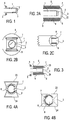
Figure 2A is a schematic view of one embodiment of the device showing the device body (6) wherein the device body defines internal guide channels (9) through which the lens cover film (3) is threaded. The lens cover film emerges out through a first guide slit (7), passes in front of the lens cover (22) and passes back into a second guide slit (8). In this view the endoscope body (1) and the objective lens (2) can be seen accommodated within the lumen of the device. The transparent lens cover (22) may be absent in other embodiments. -
Figure 2B is a schematic head-on view of the device showing the endoscope body (1), the objective lens (2), the lens cover film (3), device body (6), a first guide slit (7), a second guide slit (8). The lens cover (22) is not shown in this figure. -
Figure 2C is a perspective external view of the device showing the lens cover film (3) threaded out of the first guide slit (7) and back into the second guide slit (8), passing in front of the objective lens (not shown). -
Figure 3 is a schematic longitudinal cross-section of one embodiment of the device showing the endoscope body (1), the objective lens (2), the lens cover film (3), the first spool (4), the second spool (5), device body (6), first guide slit (7), second guide slit (8), upper frame supporting lens cover film (23), and lower frame supporting lens cover film (24). The lens cover film emerges out through a first guide slit (7), wraps around upper frame (23), passes in front of the lens (2), wraps around lower frame (24), and passes back into a second guide slit (8). In this view the endoscope body (1) and the objective lens (2) can be seen accommodated within the lumen of the device. The upper frame (23) and lower frame (24) allow the surface of the lens cover film (3) become parallel to the surface of objective lens (2). The lens cover (22) is not present in this embodiment and may be absent in other embodiments. -
Figure 4A is a schematic head-on view of the device showing the objective lens (2) inside the device body lumen, device body (6), a first guide slit (7), a second guide slit (8), upper frame supporting lens cover film (23), and lower frame supporting lens cover film (24). The lens cover film (3) is omitted in this figure in order to clearly demonstrate the 2 guide slits (with curvilinear or arc cross-sectional orientation in this embodiment). However, lens cover film (3) is present in and is an integral part of the present embodiment. -
Figure 4B is a perspective external view of the device showing the lens cover film (3) threaded out of the first guide slit (7), wraps around upper frame (23), passes in front of the objective lens (not shown), wraps around lower frame (24), and back into the second guide slit (8). The upper frame (23) and lower frame (24) are attached to device body (6) and allow the surface of the lens cover film (3) become parallel to the surface of objective lens (not shown). -
Figure 5 is a schematic longitudinal cross-section of one embodiment of the device showing the endoscope body (1), the objective lens (2), the lens cover film (3), the first spool (4), the second spool (5), device body (6), first guide slit (7), second guide slit (8), transparent lens cover (22), first additional guide slit / channel (25), and second additional guide slit / channel (26). The 2 additional slits / channels traverse along the device body and may allow passage of air, fluids, debris, or endoscopic instruments. The lens cover film emerges out through a first guide slit (7), passes in front of the lens (2) and passes back into a second guide slit (8). In this view the endoscope body (1) and the objective lens (2) can be seen accommodated within the lumen of the device with transparent lens cover (22). The lens cover (22) may be absent in other embodiments. -
Figure 6A is a schematic head-on view of the device showing the objective lens (2) inside the device body lumen, lens cover film (3), device body (6), a first guide slit (7), a second guide slit (8), first additional guide slit / channel (25), second additional guide slit / channel (26), third additional guide slit / channel (27), and fourth additional guide slit / channel (28). Any of the additional slits / channels may allow passage of air, fluids, debris, or endoscopic instruments. The number and location of the additional slits / channels may vary or may be absent in other embodiments. The transparent lens cover (22) is not shown but is present in certain embodiments including the present embodiment. -
Figure 6B is a schematic head-on view of the device showing the objective lens (2) inside the device body lumen, lens cover film (3), device body (6), a first guide slit (7), a second guide slit (8), first additional slit / channel (25), and second additional slit / channel (26). Any of the additional slits / channels may allow passage of air, fluids, debris, or endoscopic instruments. The number and location of the additional slits / channels may vary or may be absent in other embodiments. The transparent lens cover (22) is not shown but is present in certain embodiments including the present embodiment. -
Figure 6C is a schematic head-on view of the device showing the objective lens (2) inside the device body lumen, lens cover film (3), device body (6), a first guide slit (7), a second guide slit (8), first additional slit / channel (27), and second additional slit / channel (28). Any of the additional slits / channels may allow passage of air, fluids, debris, or endoscopic instruments. The number and location of the additional slits / channels may vary or may be absent in other embodiments. The transparent lens cover (22) is not shown but is present in certain embodiments including the present embodiment. -
Figure 7 is a schematic head-on view of the device showing an embodiment using and arc-wiper (10) pivotally attached by an attachment pin (11), wherein the wiper moves through an arc (12). -
Figure 8 is a schematic head-on view of the device showing an embodiment using a linear wiper (13) that moves through a path (14) perpendicular to the long edge of the wiper blade. -
Figure 9 is a schematic head-on view of the device showing an embodiment using a hemispherical sweep wiper (15) that moves through a hemispherical arc (17) similar to that of an eyelid. The hemispherical sweep wiper is pivotally attached by attachment pins (16) which act as fulcrums about which the wiper moves. -
Figure 10 is a schematic head-on view of the device showing an embodiment using a rotary wiper (18) that is pivotally attached by an attachment pin (19) mounted near the centre axis of the device and that moves in a rotational path (20) about the attachment pin in front of the lens. -
Figure 11 is a schematic head-on view of the embodiment ofFigure 8 further including a brush element (21). - Various embodiments are shown in
figures 1-11 . In one preferred embodiment the invention is a device comprising a hollow device body (6) that is designed to fit over an endoscope. The body of the device may be rigid or flexible. The body of the device may be sufficiently flexible so as to conform and mold to the contour of the endoscope. Such flexibility may be achieved by using a soft, elastic material such as latex, rubber, plastic, or a woven fabric comprising latex or other elastic fibers. The hollow device body defines a lumen shaped and sized to receive an endoscope of a particular desired size. The distal end of the device body may be open or may be closed by means of a transparent window or lens cover (22). The device body (6) may define one or more internal guide channels (9), through some of which the lens cover film (3) is threaded. The lens cover film emerges out through a first guide slit (7), passes in front of the lens cover (22) and objective lens (2), and passes back into a second guide slit (8). Guide slits 7 and 8 are preferably parallel. The entire apparatus may also be designed to fit within a trocar. - Certain embodiments include a lens cover film that is wound onto a spool. For example, a flexible lens cover film (3) may be rolled onto a first spool (4) and systematically unrolled such that it passes in front of the objective lens (2) of the endoscope (1). The lens cover film (3) can be unrolled as needed to provide a clean and clear lens cover in front of the objective lens (2). The leading end of the lens cover film may be captured and wound onto on a second spool. By winding the lens cover film onto the second spool (5) the lens cover film is pulled from the first spool, along a pre-set travel path, passing in front of the objective lens, and wound onto the second spool. The spools may be positioned at any convenient location within or external to the device. The means of winding, unwinding, or moving the lens cover film may comprise many different design variations including spools, winches, geared mechanisms, manually operated and electrically operated elements. Although spools are described in various exemplary embodiments, the invention does not require that spools be used and the lens cover film may be retained by, released from, and captured by any suitable means. Designs of such means will be readily apparent to those of skill. For example the lens cover film may be retained in a folded configuration, folded up upon itself prior to release into a pre-set travel path.
- The travel path may be defined by guides of various design sufficient to hold and guide the lens cover film along the pre-set travel path. The guide may include rails or slits through which the lens cover film passes. The guide is generally constructed as an integral part of the body of the device (6). The guide(s) and body of the device are further described in the detailed description.
- In one embodiment, the flexible lens cover film (3) is retained on a first spool, unwound and captured on a second spool such that any particular section of the lens cover film passes in front of the objective lens only once. Having become soiled, the lens cover film is incrementally wound onto the second spool and a clean section of lens cover film moves into place in front of the objective lens. In an alternative embodiment, a section of the flexible lens cover film (3) may be moved alternately bi-directionally (i.e., back and forth) in front of the objective lens (or lens cover, if present). Movement of the lens cover film through the guide slits (7 and 8) will cause a section of the lens cover film to be cleaned, and this section will then be moved back in front of the objective lens. The cleaning action may be achieved by any type of wiper or washer system, for example using blade-type wipers or sponge wipers or brush wipers. In one embodiment the guide slits (7 and 8) may be edged with flexible wiper blades, made of, for example, silicone, rubber or plastic. As the lens cover film passes between the wiper blades, solid and liquid debris is removed, and the cleaned section of film may them be repositioned in front of the objective lens. This embodiment is advantageous because it requires the use of a shorter length of lens cover film and it requires less complex apparatus to retain the film.
- The spools from and onto which the lens cover film is wound may be manipulated manually via dials mounted at the proximal end of the device. The dials may be positioned in any suitable disposition (for example see the control dials on a standard fiber-optic gastroscope). The spools may incorporate a spring biasing means (on the first spool) and a ratcheting means (on the second spool) such that the lens cover film is kept taut and can only be moved along the transit path in one direction. The control dials may incorporate gearing means by which the lens cover film may be drawn through the transit path at a slower or faster speed. The control of the movement of the spool or spools may be achieved via any means mechanically in some embodiments or electrically in other embodiments.
- In certain embodiments the device is designed to have disposable elements or to be entirely disposable. Disposability is really a function of cost in relation to expense of sterilization. Heat and chemical sterilization is a relatively inexpensive process, but it may damage certain or the more delicate elements of an apparatus. For example, the lens cover film, depending on the material from which it is made, may be clouded or otherwise damaged by heat and oxidative agents (bleach). The lens cover film may be made from any transparent material such as polythene, acetate polyvinylchloride or other polymers which are inexpensive and may be disposable. The lens cover film may be made from any transparent material that has high melting temperature and can withstand the heat generated at the endoscope objective lens (2). In certain embodiments, the lens cover film may be augmented, coated, or treated with any additional component (of any means such as chemical or electrical) to achieve anti-fog capability. Surfactant, polymer, or corona treatment, for example, may provide a hydrophilic surface to the lens cover film that can provide anti-fog quality to the film. In other embodiments, the entire device may be disposable, dispensing with the need for sterilization altogether.
- The body of the device is essentially a tube and may be made of any material (or any combination of materials) such as metal or molded plastic, for example polymers such as PTFE, polyvinylchloride, polypropylene, polyethylene, polyester or polyamide. Alternatively the body of the device may be in the form of a flexible sheath made at least partially from a material that will snuggly fit over and conform to the shape of the endoscope. Such materials include latex, rubber and woven elastic fabrics. The device may include a lens cover (22) at the distal tip, which may be made of any transparent material such as an acetate polymer and is able to withstand the heat generated at the objective lens (2) without melting or change. The guide elements (7 and 8) accommodating the lens cover film may be of any dimension and design (linear, curvilinear, arc-like, or others) on cross sectional view of the device.
- The surface of the lens cover film (3) may be made parallel to the surface of the objective lens (2) via any means, such as the use of support frames (23, 24), scaffolds, or specific device body distal tip design. The support frames, scaffolds, or distal device body tip may be made of any dimension, configuration, or material, such as nitinol that may or may not have flexibility, inherent memory or elastic properties.
- The present invention encompasses a number of different embodiments all of which remove debris and dirt from the viewing path of an endoscope. Some of these embodiments utilize a lens cover film that moves through a pre-set travel path, while others use various mechanical means to keep the viewing path and objective lens free of obstructive matter. Certain embodiments use wipers which may include flexible blades or brushes. The wipers may move through various different paths. In one embodiment, an arc-wiper (
Fig. 7 ) is pivotally attached to the body of the device by an attachment pin and moves back-and-forth through an arc. - Alternatively, the wiper may move through a linear path (
Fig 8 ) whereby the blade moves back-and-forth perpendicular to the long edge of the wiper blade. The blade may be operated via strings or wires traversing through slits or holes or tunnels within the device body. - Another exemplary embodiment uses a wiper that moves through a hemispherical arc similar to that of an eyelid (
Fig. 9 ). The wiper is pivotally attached to the device body by attachment pins which act as fulcrums or hinges about which the wiper moves. - Another example of a wiper embodiment employs a rotary wiper (
Fig. 10 ) that is pivotally attached by an attachment pin and mounted near the centre axis of the device. The wiper moves in a rotational path about the attachment pin removing dirt from front of the lens or lens cover. - Any of the wiper and brush embodiments may additionally employ a brush element or may use flexible blades of silicon, rubber, plastic or any other suitable substance. Multiple wipers and blades may optionally used in any embodiment.
- The wipers may be impelled by any standard mechanical means such as an electric motor with power being transmitted via a standard cam mechanism. A standard reciprocal gear mechanism may be employed to produce a back-and-forth motion.
- An alternate variation of the device of the invention employs a transparent lens cover coated with a coating that inherently repels fluids and other contaminants. Such a coating could, for example comprise a highly hydrophobic material such as polysiloxanes, fluoride compounds and a silane compounds. Such coatings are commercially available. Coatings can also be made so that they hold very little electrostatic charge and so that they form a very smooth molecular surface. All these qualities make a coated surface repellant to fluid and dirt. Such a coated lens cover could be employed alone or on combination with the other various embodiments of the invention.
- The device of the invention may additionally incorporate various functional elements such as light sources, vacuum means, gas and liquid conduits, instrument conduits, biopsy instruments and various instruments used to help visualize a target or perform surgical procedures. For example, one or more light sources may be set into the distal end of the body of the device to provide illumination of a target. Such light sources may be provided by one or more electric lamps (incandescent or LED) mounted at the distal end of the device or the light may be transmitted via fiber optic conduits from a remote light source to the tip of the device. A remote light source may be provided separately from the device and may be coupled to the fiber optic cables by standard couplings. In another example, the body of the device may incorporate one or more vacuum conduits that may be used to produce suction at the distal tip of the device by which fluids such as blood and other body fluids may be removed. Such devices are well known in the art. Other alternate embodiments may employ conduits within the body of the device through which a gas can be pumped; for example, air or an inert or non-reactive gas is commonly pumped into the body cavity during procedures to enhance visualization, e.g. carbon dioxide, nitrogen, etc. Conduits may also transmit fluids such as sterile water and saline that may be used to wash and clean areas to be viewed. Such liquid may be removed via the suction tube. Other conduits may be used to deliver drugs such as local anesthetics and therapeutics. Additionally, a laser conduit may be employed to transmit laser light to a target, for example for ablation and cauterization of tissue. As mentioned above, other embodiments may include instruments such as biopsy needles and cutting instruments that may be operated remotely by the user from the proximal end of the endoscope.
- The device of the invention may be fixed to the endoscope by any standard means. For example a lure-lock, strap, latch, pin or screw mechanism may be used to removeably clip the endoscope into the lumen of the invention and maintain the relative position of the endoscope and the device while in use.
- The device of the invention may be used for endoscope of different objective lens orientation (such as 0 degree, 15 degree, 30 degree, 45 degree, 60 degree, and 70 degree endoscopes). Frames (flexible or rigid, of any material or design), scaffolds (flexible or rigid, of any material or design), or distal device tip design may be used to allow the surface of lens cover film (3) become parallel to the surface of objective lens (2), thereby allowing viewing without light deflection or image distortion.
- The device of the invention may include transparent lens cover (22) integrated as part of the device body (6), thereby separating the device body lumen from device exterior surface. This would allow the use of endoscope (1) accommodated within the device body lumen without the need for sterilization of the endoscope, as the endoscope has no direct physical contact with body tissues. Additional slits or channels of various design or dimensions may be built within the device body to allow passage of air, fluids, debris, and / or endoscopic instruments. In fact, these additional slits or channels may be proximally associated with buttons, dials, openings, controls, or other designs and means and may be connected to vacuum source (for suction to remove debris from body cavity), air source (for pumping air into body cavity), or fluid irrigation source (for irrigation into body cavity). These features are particularly useful if the endoscope involved is a colonoscope, gastroscope, bronchoscope, and laryngoscope.
- Although the examples in this disclosure concentrate upon embodiments where the device is separate from an endoscope and wherein the endoscope is placed within the lumen of the device, this invention additionally encompasses embodiments where the device to keep the objective lens free of debris is incorporated into the structure of an endoscope. In its most basic embodiment the integrated endoscope embodiment comprises an endoscope having lens cover film and a means for guiding the lens cover film in front of the objective lens. In another of the simplest embodiments, the endoscope is provided with an integrated wiper means that clears debris from the viewing path. Such embodiments may employ any or all the features of the separate embodiments.
- In use, an endoscope, for example a laparoscope, is placed within the lumen of the body of the device of the invention. The objective lens of the laparoscope abuts or is in close proximity to the distal end of the tube. The distal end of the tube may be open or may terminate with a transparent window or lens cover. The entire device may be inserted into and through a standard laparoscopic trocar or a specially designed trocar. Via the trocar, the laparoscope can be placed inside the body cavity. During use the lens cover film may be moved in a preset travel path in front of the endoscope objective lens (and the lens cover, if present). The lens cover film may travel unidirectionally or bidirectionally. Any particular section may be used only once, or may be cleaned, for example by fixed wiper blades present at the guide slits, and reused by reversing the travel path of the lens cover film. In embodiments using wipers, the wiper may be activated to wipe the objective lens (and the lens cover, if present), so removing obstructive fluid and dirt.
- The shape and size of the current invention may be selected for fitness for any specific purpose. For example, the present device may be used for any of the existing laparoscopes available in the market (such as 10mm, 5mm, 2mm scopes) and may be used in conjunction with any of the existing laparoscopic trocars. Alternatively the invention may be used with specially designed laparoscopic trocars specifically designed to work with the present invention. For example, the body of the device may have a diameter of from 3mm to 25mm, or for example about 3mm, 7mm, 12 mm, 25mm, 18mm or 22mm. The length of the device may be any length compatible with its function of maintaining a clear optical/visual pathway, and the device may (or may not) be shorter than the endoscope that is inserted into it. For example, the device may be from 4cm to 30cm in length, or for example about 5cm, 7cm, 10cm, 14cm or 18cm in length. The body of the invention may be of variable fixed lengths, or it may be of dynamically adjustable length by use of a telescoping designs. The body of the invention is generally an elongated cylinder, though it may be of any suitable cross-sectional shape such as oval, triangular, square, polygonal, or polymorphous. The body of the invention may be rigid or may be flexible. A flexible body is desirable when using a flexible endoscope. The body of the device may be made from any biocompatible material, such as polyvinylchloride (PVC), polystyrene, polytetrafluoroethylene (PTFE), polypropylene, polyethylene, polyester or polyamide or other plastics or acrylics or rubber, or may be made of a metal such as a nickel-titanium alloy of stainless steel etc. The body of the device may be made from various manufacturing process(es) including heat shrinkage process. The lens cover film may be made from any transparent material such as polythene, polypropylene, polyacetates, polyvinylchloride or any other polymer materials. The lens cover film support scaffolds or frames (23 and 24) may be made from any material such as nitinol that may have memory or instrinsic elastic properties.
- The present invention provides various advantages over the prior art devices and methods. The present invention provides devices that maintain a clear and unobstructed view through the objective lens of an endoscope while in use; devices that clear obstructive fluids and debris from the optical path of an endoscope while in use, devices that eliminate the need for the endoscope to be withdrawn from the patient on order that the objective lens may be cleaned, and devices that eliminate the need for endoscope sterilization during its use. This advantage of eliminating the need for endoscope withdrawal and objective lens cleaning is particularly important as removal and reinsertion of an endoscope slows surgical procedures, increases trauma, and can significantly impact surgical outcomes. Additionally, the present invention is simple and inexpensive to manufacture, simple to use and robust in use, and can be used with a variety of endoscopic devices.
- Although the various exemplary embodiments of the present invention are directed to medical endoscopic uses, the present invention is not limited to such uses, and the device described may be used for any application in which it is important to maintain a clear optical path through the lens of a viewing instrument. The device can work equally with any type of viewing instrument or illuminating instrument to maintain a clear and unobstructed optical path. Such instruments may be used to visualize a target or to illuminate a target or both. The invention serves just as well to maintain a clear path for a beam of outgoing light as for a viewing lens. Alternative embodiments and applications include applications for sewer and drain cameras, which come in all manner of different formats. Some are similar to hand-held fiber-optic gastroscopes and can be inserted down a drain and through pipes. Others are large robotic instruments mounted on remote controlled power-trains that can be sent far along sewer pipes. Similar instruments are used to inspect gas and oil pipelines. In all these applications fouling of the optical pathway is a common and serious problem. Other applications of the current device may include providing unobstructed view to (1) lenses or cameras mounted on military vehicles or other motor vehicles such as race cars and (2) lenses or cameras used for wildlife filming or viewing. In such applications, the fouling of lenses and optical pathways by dust, fluids such as rain and mud are well known problems. Yet other embodiments include the use of the present invention to maintain a clear optical path for a photovoltaic device. The efficiency of such instruments, for example the conversion of solar energy into electrical energy by a solar panel, can be significantly diminished if small or microparticulate dust accumulates on the surface of the solar cells. This is particularly a problem encountered with the solar panels on the Mars rovers Opportunity and Spirit. Maintaining elevated levels of electrical output to the rover's storage batteries from such panels can significantly extend the useful life of the rover in such an extra-terrestrial mission. The device of the invention solves such problems in the same way as described above for the endoscopy examples. In the case of a viewing apparatus, the embodiment may involve the tubular system using a lens cover film that provides a continuously clear transparent covering for the lens or a camera and/or lamp. The lens cover film may be operated manually, electrically, robotically, or via other means. In other embodiments brushes and coated lenses may be used as described above.
- It will be readily appreciated that various adaptations and modifications of the described embodiments can be configured without departing from the scope of the invention and the above description is intended to be illustrative, and not restrictive, and it is understood that the applicant claims the full scope of any claims.
Claims (2)
- A device for maintaining a clear optical path immediately in front of the lens of a viewing apparatus or illuminating apparatus, the device comprising:a. an elongated hollow body comprising a proximal end and a distal end, wherein the elongated hollow body defines a lumen adapted to receive the viewing apparatus or illuminating apparatus;b. a first guide channel formed in the elongated hollow body terminating in a first guide slit at the distal end of the elongated hollow body and a second guide channel formed in the elongated hollow body terminating in a second guide slit at the distal end of the elongated hollow body, wherein the first guide channel is diametrically opposite and parallel to the second guide channel;c. a transparent lens cover film disposed within the elongated hollow body; wherein the transparent lens cover film is movable between the first guide channel through the first guide slit and the second guide channel through the second guide slit and passes over a means configured to allow the surface of the transparent lens cover film become parallel to the surface of the lens such that any particular section of the lens cover film passes in front of the lens of the viewing apparatus or illuminating apparatus at the distal end to provide a continuously clear transparent covering for the lens such that a clear optical path immediately in front of the lens is maintained as the lens cover film passes in front of the lens of the viewing apparatus or illuminating apparatus.
- The apparatus of claim 1, wherein the viewing apparatus comprises a camera or a video camera or wherein the viewing apparatus is an endoscope or a laparoscope.
Priority Applications (1)
| Application Number | Priority Date | Filing Date | Title |
|---|---|---|---|
| PL08768019T PL2160214T3 (en) | 2007-06-08 | 2008-05-31 | Devices for removal of debris from the objective lens of an endoscope |
Applications Claiming Priority (2)
| Application Number | Priority Date | Filing Date | Title |
|---|---|---|---|
| US93369307P | 2007-06-08 | 2007-06-08 | |
| PCT/US2008/006923 WO2008153841A2 (en) | 2007-06-08 | 2008-05-31 | Devices and methods for removal of debris from the objective lens of an endoscope |
Publications (3)
| Publication Number | Publication Date |
|---|---|
| EP2160214A2 EP2160214A2 (en) | 2010-03-10 |
| EP2160214A4 EP2160214A4 (en) | 2013-03-06 |
| EP2160214B1 true EP2160214B1 (en) | 2018-10-31 |
Family
ID=40130394
Family Applications (2)
| Application Number | Title | Priority Date | Filing Date |
|---|---|---|---|
| EP08768020.3A Not-in-force EP2157917B1 (en) | 2007-06-08 | 2008-05-31 | Devices for closure of wounds |
| EP08768019.5A Active EP2160214B1 (en) | 2007-06-08 | 2008-05-31 | Devices for removal of debris from the objective lens of an endoscope |
Family Applications Before (1)
| Application Number | Title | Priority Date | Filing Date |
|---|---|---|---|
| EP08768020.3A Not-in-force EP2157917B1 (en) | 2007-06-08 | 2008-05-31 | Devices for closure of wounds |
Country Status (5)
| Country | Link |
|---|---|
| US (3) | US9241613B2 (en) |
| EP (2) | EP2157917B1 (en) |
| ES (1) | ES2708428T3 (en) |
| PL (1) | PL2160214T3 (en) |
| WO (2) | WO2008153841A2 (en) |
Families Citing this family (123)
| Publication number | Priority date | Publication date | Assignee | Title |
|---|---|---|---|---|
| US10307041B2 (en) | 2007-06-08 | 2019-06-04 | Medeon Biodesign, Inc. | Lens cover modification |
| EP2157917B1 (en) | 2007-06-08 | 2021-11-10 | Medeon Biodesign, Inc. | Devices for closure of wounds |
| US9241610B2 (en) | 2009-12-08 | 2016-01-26 | Medeon Biodesign, Inc. | Devices and methods for removal of debris from the objective lens of an endoscope |
| JP4526601B2 (en) * | 2008-10-16 | 2010-08-18 | オリンパスメディカルシステムズ株式会社 | Medical equipment |
| US8944997B2 (en) * | 2009-01-16 | 2015-02-03 | Board Of Regents, The University Of Texas System | Medical devices and methods |
| JP4531129B1 (en) * | 2009-03-05 | 2010-08-25 | オリンパスメディカルシステムズ株式会社 | Medical equipment |
| US9474440B2 (en) | 2009-06-18 | 2016-10-25 | Endochoice, Inc. | Endoscope tip position visual indicator and heat management system |
| US9713417B2 (en) | 2009-06-18 | 2017-07-25 | Endochoice, Inc. | Image capture assembly for use in a multi-viewing elements endoscope |
| US9402533B2 (en) | 2011-03-07 | 2016-08-02 | Endochoice Innovation Center Ltd. | Endoscope circuit board assembly |
| US11547275B2 (en) | 2009-06-18 | 2023-01-10 | Endochoice, Inc. | Compact multi-viewing element endoscope system |
| US9101287B2 (en) | 2011-03-07 | 2015-08-11 | Endochoice Innovation Center Ltd. | Multi camera endoscope assembly having multiple working channels |
| EP2865322B1 (en) | 2009-06-18 | 2020-07-22 | EndoChoice, Inc. | Multi-camera endoscope |
| US11278190B2 (en) | 2009-06-18 | 2022-03-22 | Endochoice, Inc. | Multi-viewing element endoscope |
| US11864734B2 (en) | 2009-06-18 | 2024-01-09 | Endochoice, Inc. | Multi-camera endoscope |
| US10130246B2 (en) | 2009-06-18 | 2018-11-20 | Endochoice, Inc. | Systems and methods for regulating temperature and illumination intensity at the distal tip of an endoscope |
| US9101268B2 (en) | 2009-06-18 | 2015-08-11 | Endochoice Innovation Center Ltd. | Multi-camera endoscope |
| US9901244B2 (en) | 2009-06-18 | 2018-02-27 | Endochoice, Inc. | Circuit board assembly of a multiple viewing elements endoscope |
| US8926502B2 (en) | 2011-03-07 | 2015-01-06 | Endochoice, Inc. | Multi camera endoscope having a side service channel |
| US9706903B2 (en) | 2009-06-18 | 2017-07-18 | Endochoice, Inc. | Multiple viewing elements endoscope system with modular imaging units |
| US10165929B2 (en) | 2009-06-18 | 2019-01-01 | Endochoice, Inc. | Compact multi-viewing element endoscope system |
| US9492063B2 (en) | 2009-06-18 | 2016-11-15 | Endochoice Innovation Center Ltd. | Multi-viewing element endoscope |
| US9872609B2 (en) | 2009-06-18 | 2018-01-23 | Endochoice Innovation Center Ltd. | Multi-camera endoscope |
| WO2012077116A1 (en) * | 2010-12-09 | 2012-06-14 | Peermedical Ltd. | Flexible electronic circuit board for a multi-camera endoscope |
| US12137873B2 (en) | 2009-06-18 | 2024-11-12 | Endochoice, Inc. | Compact multi-viewing element endoscope system |
| US10524645B2 (en) | 2009-06-18 | 2020-01-07 | Endochoice, Inc. | Method and system for eliminating image motion blur in a multiple viewing elements endoscope |
| US9642513B2 (en) | 2009-06-18 | 2017-05-09 | Endochoice Inc. | Compact multi-viewing element endoscope system |
| GB2474309B (en) | 2009-10-12 | 2011-09-07 | Endoguard Ltd | Flow guide for an endoscope |
| US12220105B2 (en) | 2010-06-16 | 2025-02-11 | Endochoice, Inc. | Circuit board assembly of a multiple viewing elements endoscope |
| US20120000024A1 (en) * | 2010-06-30 | 2012-01-05 | Raytheon Company | Automated camera cleaning system |
| EP4233680B1 (en) | 2010-09-20 | 2025-06-18 | EndoChoice, Inc. | Endoscope distal section comprising a unitary fluid channeling component |
| US9560953B2 (en) | 2010-09-20 | 2017-02-07 | Endochoice, Inc. | Operational interface in a multi-viewing element endoscope |
| US8690764B2 (en) | 2010-10-20 | 2014-04-08 | Covidien Lp | Endoscope cleaner |
| US20120108904A1 (en) * | 2010-10-20 | 2012-05-03 | Yong Ma | Cleaner for endoscope |
| US9763567B2 (en) * | 2010-10-20 | 2017-09-19 | Covidien Lp | Endoscope wiper blade cleaner |
| JP5944912B2 (en) | 2010-10-28 | 2016-07-05 | エンドチョイス イノベーション センター リミテッド | Optical system for multi-sensor endoscope |
| US10663714B2 (en) | 2010-10-28 | 2020-05-26 | Endochoice, Inc. | Optical system for an endoscope |
| US9706908B2 (en) | 2010-10-28 | 2017-07-18 | Endochoice, Inc. | Image capture and video processing systems and methods for multiple viewing element endoscopes |
| US12204087B2 (en) | 2010-10-28 | 2025-01-21 | Endochoice, Inc. | Optical systems for multi-sensor endoscopes |
| EP2648602B1 (en) | 2010-12-09 | 2018-07-18 | EndoChoice Innovation Center Ltd. | Flexible electronic circuit board multi-camera endoscope |
| US11889986B2 (en) | 2010-12-09 | 2024-02-06 | Endochoice, Inc. | Flexible electronic circuit board for a multi-camera endoscope |
| US20120178995A1 (en) * | 2011-01-05 | 2012-07-12 | Parametric Mechanisms, LLC | Method and Apparatus for Cleaning the Field of View of an Endoscopic Lens |
| US10517464B2 (en) | 2011-02-07 | 2019-12-31 | Endochoice, Inc. | Multi-element cover for a multi-camera endoscope |
| EP2672878B1 (en) | 2011-02-07 | 2017-11-22 | Endochoice Innovation Center Ltd. | Multi-element cover for a multi-camera endoscope |
| US20120238818A1 (en) * | 2011-02-09 | 2012-09-20 | O'prey Cormac | Covering Apparatus For An Endoscope Lens |
| US9211060B2 (en) * | 2011-04-05 | 2015-12-15 | Covidien Lp | Visualization device and holder for use with a tracheal tube |
| DE102011100232A1 (en) * | 2011-05-02 | 2012-11-08 | Karl Storz Gmbh & Co. Kg | Desiccant arrangement for optical instruments |
| US9204939B2 (en) * | 2011-08-21 | 2015-12-08 | M.S.T. Medical Surgery Technologies Ltd. | Device and method for assisting laparoscopic surgery—rule based approach |
| US8708889B2 (en) | 2011-10-24 | 2014-04-29 | Trocare, LLC | Jawed trocar assembly |
| CA2798729A1 (en) | 2011-12-13 | 2013-06-13 | Peermedical Ltd. | Rotatable connector for an endoscope |
| EP2604175B1 (en) | 2011-12-13 | 2019-11-20 | EndoChoice Innovation Center Ltd. | Removable tip endoscope |
| US20130274768A1 (en) | 2012-02-29 | 2013-10-17 | Marker Medical, Llc | Surgical apparatus and method |
| WO2013177469A1 (en) * | 2012-05-23 | 2013-11-28 | Veritract | Elongate medical instrument with sheath |
| US9560954B2 (en) | 2012-07-24 | 2017-02-07 | Endochoice, Inc. | Connector for use with endoscope |
| US10595719B2 (en) | 2012-08-01 | 2020-03-24 | Ronald Hurst | System and method for cleaning a cannula during a surgical procedure using a hinged tip |
| WO2014063106A1 (en) * | 2012-10-18 | 2014-04-24 | The Arizona Board Of Regents On Behalf Of The University Of Arizona | Multi-resolution foveated endoscope/laparoscope |
| NO342734B1 (en) * | 2012-11-01 | 2018-08-06 | Vision Io As | Sensor cover for a pipe inspection structure |
| US9993142B2 (en) | 2013-03-28 | 2018-06-12 | Endochoice, Inc. | Fluid distribution device for a multiple viewing elements endoscope |
| US9636003B2 (en) | 2013-06-28 | 2017-05-02 | Endochoice, Inc. | Multi-jet distributor for an endoscope |
| US9986899B2 (en) | 2013-03-28 | 2018-06-05 | Endochoice, Inc. | Manifold for a multiple viewing elements endoscope |
| US10595714B2 (en) | 2013-03-28 | 2020-03-24 | Endochoice, Inc. | Multi-jet controller for an endoscope |
| US12207796B2 (en) | 2013-03-28 | 2025-01-28 | Endochoice Inc. | Multi-jet controller for an endoscope |
| JP6669647B2 (en) | 2013-05-07 | 2020-03-18 | エンドチョイス インコーポレイテッドEndochoice, Inc. | White balance correction device for use with endoscope and method of performing white balance correction |
| US10499794B2 (en) | 2013-05-09 | 2019-12-10 | Endochoice, Inc. | Operational interface in a multi-viewing element endoscope |
| US9949623B2 (en) | 2013-05-17 | 2018-04-24 | Endochoice, Inc. | Endoscope control unit with braking system |
| TWI563959B (en) * | 2013-06-17 | 2017-01-01 | 國立臺灣大學 | An endoscope and a method for chemical modification of the members thereof |
| US9510823B2 (en) | 2013-08-02 | 2016-12-06 | Covidien Lp | Devices, systems, and methods for wound closure |
| US10064541B2 (en) | 2013-08-12 | 2018-09-04 | Endochoice, Inc. | Endoscope connector cover detection and warning system |
| US9943218B2 (en) | 2013-10-01 | 2018-04-17 | Endochoice, Inc. | Endoscope having a supply cable attached thereto |
| CA2866035A1 (en) | 2013-10-04 | 2015-04-04 | Tidi Products, Llc | Sheath for a medical or dental instrument |
| WO2015089038A1 (en) | 2013-12-09 | 2015-06-18 | Teleflex Medical Incorporated | Laparoscopic fascial closure system |
| US9968242B2 (en) | 2013-12-18 | 2018-05-15 | Endochoice, Inc. | Suction control unit for an endoscope having two working channels |
| AU2014376195B2 (en) * | 2013-12-20 | 2018-08-30 | Medeon Biodesign, Inc. | Lens cover modification |
| WO2015112747A2 (en) | 2014-01-22 | 2015-07-30 | Endochoice, Inc. | Image capture and video processing systems and methods for multiple viewing element endoscopes |
| US9913576B2 (en) * | 2014-02-02 | 2018-03-13 | Neil Anjon Ray | Laparoscope |
| DE102014202075B4 (en) | 2014-02-05 | 2018-03-01 | Deutsches Zentrum für Luft- und Raumfahrt e.V. | Camera system and method for cleaning a camera |
| WO2015140065A1 (en) * | 2014-03-17 | 2015-09-24 | X-Med S.R.L. | Protection device for diagnostic instruments of the optical type and corresponding method of manufacture |
| US11234581B2 (en) | 2014-05-02 | 2022-02-01 | Endochoice, Inc. | Elevator for directing medical tool |
| JP2017527332A (en) | 2014-07-21 | 2017-09-21 | エンドチョイス インコーポレイテッドEndochoice, Inc. | Multifocal multi-camera endoscope system |
| EP3185744B1 (en) | 2014-08-29 | 2024-10-23 | EndoChoice, Inc. | Systems and methods for varying stiffness of an endoscopic insertion tube |
| WO2016100173A1 (en) | 2014-12-18 | 2016-06-23 | Endochoice, Inc. | System and method for processing video images generated by a multiple viewing elements endoscope |
| EP3242584B1 (en) | 2015-01-05 | 2020-07-22 | EndoChoice, Inc. | Tubed manifold of a multiple viewing elements endoscope |
| US10511748B2 (en) | 2015-01-30 | 2019-12-17 | Robert Bosch Gmbh | Electrostatic lens cleaning |
| US10376181B2 (en) | 2015-02-17 | 2019-08-13 | Endochoice, Inc. | System for detecting the location of an endoscopic device during a medical procedure |
| US12529882B2 (en) | 2015-02-24 | 2026-01-20 | Endochoice, Inc. | Optical system for an endoscope |
| US10078207B2 (en) | 2015-03-18 | 2018-09-18 | Endochoice, Inc. | Systems and methods for image magnification using relative movement between an image sensor and a lens assembly |
| US10401611B2 (en) | 2015-04-27 | 2019-09-03 | Endochoice, Inc. | Endoscope with integrated measurement of distance to objects of interest |
| EP3747349A1 (en) | 2015-05-17 | 2020-12-09 | Endochoice, Inc. | Endoscopic image enhancement using contrast limited adaptive histogram equalization (clahe) implemented in a processor |
| CN114795472B (en) | 2015-10-28 | 2024-11-08 | 安多卓思公司 | Apparatus and method for tracking the position of an endoscope within a patient's body |
| CN113425225B (en) | 2015-11-24 | 2024-09-17 | 安多卓思公司 | Disposable Air/Water Valves and Suction Valves for Endoscopes |
| US10548626B2 (en) * | 2015-12-15 | 2020-02-04 | Boston Scientific Scimed, Inc. | Endoscopic tissue manipulation tool |
| EP3419497B1 (en) | 2016-02-24 | 2022-06-01 | Endochoice, Inc. | Circuit board assembly for a multiple viewing element endoscope using cmos sensors |
| WO2017160792A1 (en) | 2016-03-14 | 2017-09-21 | Endochoice, Inc. | System and method for guiding and tracking a region of interest using an endoscope |
| CN109310408B (en) | 2016-06-21 | 2021-11-23 | 安多卓思公司 | Endoscope system with multiple connection interfaces for connection to different video data signal sources |
| US10709321B2 (en) | 2016-07-13 | 2020-07-14 | Washington University | Self-cleaning endoscope |
| US10863980B2 (en) * | 2016-12-28 | 2020-12-15 | Edwards Lifesciences Corporation | Suture fastener having spaced-apart layers |
| CN107582014B (en) * | 2017-10-12 | 2024-08-27 | 无锡市人民医院 | A hard lens protection sleeve |
| WO2019204116A1 (en) * | 2018-04-19 | 2019-10-24 | Terumo Cardiovascular Systems Corporation | Flexible camera system for minimally invasive surgery |
| US11234690B2 (en) * | 2018-05-02 | 2022-02-01 | Covidien Lp | Method and device for closing a port site incision |
| US10188483B1 (en) | 2018-08-03 | 2019-01-29 | Phong Duy Bui | Gastro-intestinal scope sterilization, disinfection and storage device and methods of making and using same |
| US10525156B1 (en) | 2018-08-03 | 2020-01-07 | Phong Duy Bui | Method of using a gastro-intestinal scope for the disinfection of a colon |
| US11510561B2 (en) * | 2018-08-21 | 2022-11-29 | Verily Life Sciences Llc | Endoscope defogging |
| US11412921B2 (en) | 2018-10-02 | 2022-08-16 | Covidien Lp | Multi lumen access device |
| WO2020112852A1 (en) | 2018-11-29 | 2020-06-04 | Board Of Regents, The University Of Texas System | Devices, systems and methods for cleaning of elongated instrument surface |
| CN109831611A (en) * | 2019-03-22 | 2019-05-31 | 司文 | A kind of freeway tunnel monitoring roller type automatically cleaning camera lens shield |
| US11154187B2 (en) | 2019-05-29 | 2021-10-26 | Peter H. Kwon | Apparatus and method for in vivo cleaning of an optical lens of a surgical visualization device |
| WO2020243270A1 (en) | 2019-05-29 | 2020-12-03 | Stryker Corporation | Systems and methods for intraoperative surgical scope cleaning |
| US11357542B2 (en) | 2019-06-21 | 2022-06-14 | Covidien Lp | Valve assembly and retainer for surgical access assembly |
| US11439429B2 (en) | 2019-07-11 | 2022-09-13 | New View Surgical | Cannula assembly with deployable camera |
| EP3769658A1 (en) * | 2019-07-23 | 2021-01-27 | National University of Ireland Galway | A scope |
| US12357159B2 (en) | 2019-09-27 | 2025-07-15 | The Government of the United States, as represented by the Director of the Defense Health Agency | Surgical scope with removable lumen |
| US11284789B2 (en) | 2019-10-04 | 2022-03-29 | ClearCam, Inc. | Imaging element cleaning apparatus with structure-mandated cleaning member motion control |
| US11375887B2 (en) | 2019-10-04 | 2022-07-05 | ClearCam Inc. | Imaging element cleaning apparatus |
| US10791918B1 (en) | 2019-10-04 | 2020-10-06 | ClearCam Inc. | Imaging element cleaning apparatus |
| US20230016459A1 (en) * | 2019-12-17 | 2023-01-19 | GI Scientific, LLC | Optical components for endoscope companion devices |
| US20210196319A1 (en) * | 2019-12-29 | 2021-07-01 | Biosense Webster (Israel) Ltd | Trocar with internal camera providing tilted view angle |
| US11013399B1 (en) | 2020-01-27 | 2021-05-25 | Board Of Regents, The University Of Texas System | Wiper assembly for imaging element cleaning apparatus |
| US11850106B2 (en) * | 2020-05-06 | 2023-12-26 | Covidien Lp | Cleaning cap for a surgical access device |
| US11033179B1 (en) | 2020-06-12 | 2021-06-15 | ClearCam Inc. | Method for placement of an imaging element cleaning apparatus and obturator for enabling same |
| CN112401825A (en) * | 2020-11-27 | 2021-02-26 | 瑞惜康(苏州)医疗科技有限公司 | Prevent atomizing peritoneoscope of camera lens pollution |
| US10993609B1 (en) | 2021-01-23 | 2021-05-04 | ClearCam Inc. | Imaging element cleaning device with imaging device fitment adjustability |
| US11109940B1 (en) | 2021-02-09 | 2021-09-07 | ClearCam Inc. | Devices, apparatuses, systems and methods for facilitating cleaning of an imaging element of an imaging device |
| US11766309B2 (en) | 2021-03-09 | 2023-09-26 | ClearCam Inc. | Articles, kits and methods adapted for facilitating adjustability of operative apparatuses |
| US11707189B1 (en) | 2022-02-10 | 2023-07-25 | ClearCam Inc. | Methods, devices and systems for cleaning an imaging element with a translatable cleaning element |
Citations (1)
| Publication number | Priority date | Publication date | Assignee | Title |
|---|---|---|---|---|
| JPS5263985U (en) * | 1975-11-08 | 1977-05-11 |
Family Cites Families (86)
| Publication number | Priority date | Publication date | Assignee | Title |
|---|---|---|---|---|
| US3145249A (en) | 1962-01-02 | 1964-08-18 | Bausch & Lomb | Endoscope window |
| US4524920A (en) | 1982-07-20 | 1985-06-25 | Olympus Optical Co., Ltd. | Film cassette |
| JPS6169019A (en) | 1984-09-13 | 1986-04-09 | Katsuyuki Totsu | Automatic cleaning system of lens front in television camera for monitor |
| GB2188746A (en) | 1986-04-02 | 1987-10-07 | Amalgamated Television Service | Protecting lens using fed transparent film |
| US5041129A (en) | 1990-07-02 | 1991-08-20 | Acufex Microsurgical, Inc. | Slotted suture anchor and method of anchoring a suture |
| US5167220A (en) | 1990-08-09 | 1992-12-01 | Brown Cathy K | Systems and methods for maintaining a clear visual field during endoscopic procedures |
| US5225001A (en) | 1990-09-19 | 1993-07-06 | Healthtek | Single channel scope cleaning method and apparatus |
| US5085661A (en) | 1990-10-29 | 1992-02-04 | Gerald Moss | Surgical fastener implantation device |
| US5149329A (en) | 1990-12-12 | 1992-09-22 | Wayne State University | Surgical suture carrier and method for urinary bladder neck suspension |
| US5320629B1 (en) | 1991-01-07 | 2000-05-02 | Advanced Surgical Inc | Device and method for applying suture |
| US5207213A (en) | 1991-02-01 | 1993-05-04 | Circon Corporation | Laparoscope having means for removing image impeding material from a distal lens |
| US5354298A (en) | 1991-03-22 | 1994-10-11 | United States Surgical Corporation | Suture anchor installation system |
| EP0549739A4 (en) | 1991-05-14 | 1995-07-05 | Mervyn John Murdoch | Laparoscopic telescope lens cleaner and protector |
| US5281234A (en) | 1991-10-30 | 1994-01-25 | Wilk Peter J | Laparoscopic surgical method and related instrument assembly |
| DE4137218C1 (en) | 1991-11-13 | 1993-02-11 | Heidmueller, Harald, 5000 Koeln, De | |
| US5433722A (en) | 1992-01-08 | 1995-07-18 | Sharpe Endosurgical Corporation | Ligature carrier for endoscopic use |
| US5217486A (en) * | 1992-02-18 | 1993-06-08 | Mitek Surgical Products, Inc. | Suture anchor and installation tool |
| US5403328A (en) | 1992-04-22 | 1995-04-04 | United States Surgical Corporation | Surgical apparatus and method for suturing body tissue |
| US5368601A (en) | 1992-04-30 | 1994-11-29 | Lasersurge, Inc. | Trocar wound closure device |
| US5458609A (en) | 1992-09-04 | 1995-10-17 | Laurus Medical Corporation | Surgical needle and retainer system |
| US5540704A (en) * | 1992-09-04 | 1996-07-30 | Laurus Medical Corporation | Endoscopic suture system |
| US5339800A (en) | 1992-09-10 | 1994-08-23 | Devmed Group Inc. | Lens cleaning means for invasive viewing medical instruments with anti-contamination means |
| US5387227A (en) | 1992-09-10 | 1995-02-07 | Grice; O. Drew | Method for use of a laparo-suture needle |
| CA2106127A1 (en) | 1992-09-23 | 1994-03-24 | Peter W.J. Hinchliffe | Instrument for closing trocar puncture wounds |
| US5281237A (en) | 1992-09-25 | 1994-01-25 | Gimpelson Richard J | Surgical stitching device and method of use |
| US5222508A (en) | 1992-10-09 | 1993-06-29 | Osvaldo Contarini | Method for suturing punctures of the human body |
| US5469841A (en) | 1992-10-29 | 1995-11-28 | Olympus Optical Co., Ltd. | Endoscope apparatus provided with liquid removing mechanism for the electric connector |
| US5336239A (en) | 1993-01-15 | 1994-08-09 | Gimpelson Richard J | Surgical needle |
| US5363843A (en) * | 1993-03-16 | 1994-11-15 | Yousef Daneshvar | Special instrument covers |
| US5374275A (en) | 1993-03-25 | 1994-12-20 | Synvasive Technology, Inc. | Surgical suturing device and method of use |
| US5503634A (en) | 1993-04-28 | 1996-04-02 | Christy; William J. | Surgical stab wound closure device and method |
| US5350385A (en) | 1993-04-28 | 1994-09-27 | Christy William J | Surgical stab wound closure device and method |
| US5391182A (en) | 1993-08-03 | 1995-02-21 | Origin Medsystems, Inc. | Apparatus and method for closing puncture wounds |
| US5507755A (en) * | 1993-08-03 | 1996-04-16 | Origin Medsystems, Inc. | Apparatus and method for closing puncture wounds |
| US5575756A (en) | 1993-08-16 | 1996-11-19 | Olympus Optical Co., Ltd. | Endoscope apparatus |
| US5827299A (en) | 1993-08-25 | 1998-10-27 | Inlet Medical, Inc | Insertable suture passing grasping probe and methodology for using same |
| US5496335A (en) | 1993-08-25 | 1996-03-05 | Inlet Medical, Inc. | Insertable suture passing grasping probe and methodology for using same |
| US5392766A (en) * | 1993-10-06 | 1995-02-28 | Innerdyne Medical, Inc. | System and method for cleaning viewing scope lenses |
| DE4345147B4 (en) | 1993-10-06 | 2006-05-11 | Dornier, Irén | Motor vehicle with at least one rear-facing video camera |
| US5462560A (en) | 1993-10-08 | 1995-10-31 | Tahoe Surgical Instruments | Double needle ligature device |
| US5468251A (en) | 1993-10-12 | 1995-11-21 | Advanced Surgical, Inc. | Surgical suturing device |
| US5439469A (en) | 1993-11-05 | 1995-08-08 | Advanced Surgical, Inc. | Wound closure device |
| US5562688A (en) | 1994-03-25 | 1996-10-08 | Riza; Erol D. | Apparatus facilitating suturing in laparoscopic surgery |
| US5464008A (en) | 1994-04-14 | 1995-11-07 | Kim; John H. | Laparoscope defogging |
| AU2603295A (en) | 1994-05-24 | 1995-12-18 | Robert W. Bailey | Irrigating laparoscopic cannula or trocar |
| US6017333A (en) | 1995-04-13 | 2000-01-25 | Bailey; Robert W. | Irrigating laparoscopic cannula |
| US5514084A (en) | 1994-07-26 | 1996-05-07 | Fisher; Yale | Retractable wipe for cleaning endoscopic surgical devices |
| US5499991A (en) | 1994-12-19 | 1996-03-19 | Linvatec Corporation | Endoscopic needle with suture retriever |
| US5591180A (en) * | 1995-04-19 | 1997-01-07 | United States Surgical Corporation | Surgical suturing apparatus |
| US5626558A (en) | 1995-05-05 | 1997-05-06 | Suson; John | Adjustable flow rate glaucoma shunt and method of using same |
| US5549543A (en) | 1995-06-01 | 1996-08-27 | Kim; Il G. | Laparoscopic defogging apparatus |
| US6562052B2 (en) * | 1995-08-24 | 2003-05-13 | Sutura, Inc. | Suturing device and method |
| US5653717A (en) | 1995-08-28 | 1997-08-05 | Urohealth Systems, Inc. | Wound closure device |
| US5626614A (en) | 1995-12-22 | 1997-05-06 | Applied Medical Resources Corporation | T-anchor suturing device and method for using same |
| US5830127A (en) | 1996-08-05 | 1998-11-03 | Cybersonics, Inc. | Method and apparatus for cleaning endoscopes and the like |
| JP3431771B2 (en) | 1996-09-27 | 2003-07-28 | シャープ株式会社 | Electronics |
| SE508772C2 (en) * | 1997-01-31 | 1998-11-02 | Sven A Swallert | Device with an aperture covered by a glass plate or lens |
| US5817112A (en) | 1997-09-22 | 1998-10-06 | Surgical Inventions & Innovations, Inc | Christoudias fascial closure device |
| IL122111A (en) | 1997-11-04 | 2004-06-01 | Sightline Techn Ltd | Video rectoscope |
| US20030109837A1 (en) | 1998-03-13 | 2003-06-12 | Mcbride-Sakal Marcia | Brush to clear occluded stents |
| US6488691B1 (en) | 1998-06-24 | 2002-12-03 | Brendan J. Carroll | Laparascopic incision closure device |
| US6066146A (en) | 1998-06-24 | 2000-05-23 | Carroll; Brendan J. | Laparascopic incision closure device |
| US6712479B1 (en) | 1998-07-30 | 2004-03-30 | Innovative Surgical Technology, Inc. | Method for preventing laparoscope fogging |
| US6234635B1 (en) | 1998-07-30 | 2001-05-22 | Michael R. Seitzinger | Method for preventing laparoscope fogging |
| US7563267B2 (en) * | 1999-04-09 | 2009-07-21 | Evalve, Inc. | Fixation device and methods for engaging tissue |
| US6447446B1 (en) | 1999-11-02 | 2002-09-10 | Medtronic Xomed, Inc. | Method and apparatus for cleaning an endoscope lens |
| US6354992B1 (en) | 1999-11-08 | 2002-03-12 | Daniel T. Kato | Automated laparoscopic lens cleaner |
| US6197042B1 (en) * | 2000-01-05 | 2001-03-06 | Medical Technology Group, Inc. | Vascular sheath with puncture site closure apparatus and methods of use |
| EP1303218A1 (en) * | 2000-06-14 | 2003-04-23 | Sterilis, Inc. | Suturing method and apparatus |
| AU2001288599A1 (en) * | 2000-09-01 | 2002-03-13 | Advanced Vascular Technologies, Llc | Vascular bypass grafting instrument and method |
| JP3845296B2 (en) | 2000-11-29 | 2006-11-15 | オリンパス株式会社 | Endoscope dirt remover |
| US6500184B1 (en) | 2001-01-31 | 2002-12-31 | Yung C. Chan | Suturing apparatus and method of suturing |
| JP3671002B2 (en) * | 2001-12-28 | 2005-07-13 | オリンパス株式会社 | Endoscope sheath |
| US20040087978A1 (en) | 2002-08-27 | 2004-05-06 | Velez Juan Manuel | Surgical fascia closure instrument, guide and method |
| US20040068273A1 (en) * | 2002-10-02 | 2004-04-08 | Ibionics Corporation | Automatic laparoscopic incision closing apparatus |
| US20040249412A1 (en) | 2003-06-04 | 2004-12-09 | Snow Brent W. | Apparatus and methods for puncture site closure |
| JP2005052229A (en) | 2003-08-07 | 2005-03-03 | Olympus Corp | Visual field securing device |
| US7320693B2 (en) | 2003-08-21 | 2008-01-22 | Pollak Stanley B | Methods and instruments for closing laparoscopic trocar puncture wounds |
| US7811228B2 (en) * | 2004-07-26 | 2010-10-12 | Medtronic Xomed, Inc. | Disposable endoscope sheath having adjustable length |
| US8992549B2 (en) * | 2004-08-05 | 2015-03-31 | Teleflex Medical Incorporated | Laparoscopic port site closure tool |
| US8333777B2 (en) * | 2005-04-22 | 2012-12-18 | Benvenue Medical, Inc. | Catheter-based tissue remodeling devices and methods |
| US20070049794A1 (en) * | 2005-09-01 | 2007-03-01 | Ezc Medical Llc | Visualization stylet for medical device applications having self-contained power source |
| JP4756986B2 (en) | 2005-10-14 | 2011-08-24 | オリンパスメディカルシステムズ株式会社 | Endoscope sheath and endoscope device |
| US20080081948A1 (en) * | 2006-10-03 | 2008-04-03 | Ethicon Endo-Surgery, Inc. | Apparatus for cleaning a distal scope end of a medical viewing scope |
| EP2157917B1 (en) * | 2007-06-08 | 2021-11-10 | Medeon Biodesign, Inc. | Devices for closure of wounds |
| JP4531130B2 (en) * | 2008-10-29 | 2010-08-25 | オリンパスメディカルシステムズ株式会社 | Medical equipment |
-
2008
- 2008-05-31 EP EP08768020.3A patent/EP2157917B1/en not_active Not-in-force
- 2008-05-31 EP EP08768019.5A patent/EP2160214B1/en active Active
- 2008-05-31 US US12/663,579 patent/US9241613B2/en not_active Expired - Fee Related
- 2008-05-31 WO PCT/US2008/006923 patent/WO2008153841A2/en not_active Ceased
- 2008-05-31 WO PCT/US2008/006924 patent/WO2009002390A1/en not_active Ceased
- 2008-05-31 PL PL08768019T patent/PL2160214T3/en unknown
- 2008-05-31 US US12/663,573 patent/US8979738B2/en active Active
- 2008-05-31 ES ES08768019T patent/ES2708428T3/en active Active
-
2016
- 2016-01-19 US US15/001,002 patent/US10314566B2/en not_active Expired - Fee Related
Patent Citations (1)
| Publication number | Priority date | Publication date | Assignee | Title |
|---|---|---|---|---|
| JPS5263985U (en) * | 1975-11-08 | 1977-05-11 |
Also Published As
| Publication number | Publication date |
|---|---|
| US20100174144A1 (en) | 2010-07-08 |
| EP2160214A2 (en) | 2010-03-10 |
| EP2157917A1 (en) | 2010-03-03 |
| WO2009002390A1 (en) | 2008-12-31 |
| ES2708428T3 (en) | 2019-04-09 |
| US10314566B2 (en) | 2019-06-11 |
| US20160128681A1 (en) | 2016-05-12 |
| US20100185217A1 (en) | 2010-07-22 |
| EP2157917A4 (en) | 2016-06-08 |
| US9241613B2 (en) | 2016-01-26 |
| EP2160214A4 (en) | 2013-03-06 |
| WO2008153841A2 (en) | 2008-12-18 |
| WO2008153841A3 (en) | 2009-02-05 |
| EP2157917B1 (en) | 2021-11-10 |
| PL2160214T3 (en) | 2019-06-28 |
| US8979738B2 (en) | 2015-03-17 |
Similar Documents
| Publication | Publication Date | Title |
|---|---|---|
| US8979738B2 (en) | Devices and methods for removal of debris from the objective lens of an endoscope | |
| US9241610B2 (en) | Devices and methods for removal of debris from the objective lens of an endoscope | |
| US10986982B2 (en) | Lens cover modification | |
| CA2937148C (en) | Lens cover modification | |
| US10335021B2 (en) | Endoscope wiper blade cleaner | |
| US6371909B1 (en) | Apparatus and method for providing spherical viewing during endoscopic procedures | |
| US8262561B2 (en) | Hygiene protection for endoscopes | |
| JP2007520287A (en) | Endoscope with flexible probe | |
| US20120108904A1 (en) | Cleaner for endoscope | |
| CA3120320A1 (en) | Devices, systems and methods for cleaning of elongated instrument surface | |
| US10709321B2 (en) | Self-cleaning endoscope | |
| JP7777871B2 (en) | Optical components for endoscopic companion devices | |
| WO2010067762A1 (en) | Observation device and endoscope device | |
| CN114424922A (en) | Duct assemblies and endoscopes | |
| JP2005237819A (en) | Endoscope |
Legal Events
| Date | Code | Title | Description |
|---|---|---|---|
| PUAI | Public reference made under article 153(3) epc to a published international application that has entered the european phase |
Free format text: ORIGINAL CODE: 0009012 |
|
| 17P | Request for examination filed |
Effective date: 20100105 |
|
| AK | Designated contracting states |
Kind code of ref document: A2 Designated state(s): AT BE BG CH CY CZ DE DK EE ES FI FR GB GR HR HU IE IS IT LI LT LU LV MC MT NL NO PL PT RO SE SI SK TR |
|
| AX | Request for extension of the european patent |
Extension state: AL BA MK RS |
|
| DAX | Request for extension of the european patent (deleted) | ||
| A4 | Supplementary search report drawn up and despatched |
Effective date: 20130206 |
|
| RIC1 | Information provided on ipc code assigned before grant |
Ipc: A61B 1/12 20060101ALI20130131BHEP Ipc: A61M 5/00 20060101AFI20130131BHEP |
|
| 17Q | First examination report despatched |
Effective date: 20131008 |
|
| RAP1 | Party data changed (applicant data changed or rights of an application transferred) |
Owner name: MEDEON BIOSURGICAL, INC. |
|
| RIN1 | Information on inventor provided before grant (corrected) |
Inventor name: MEDEON BIOSURGICAL, INC. |
|
| RAP1 | Party data changed (applicant data changed or rights of an application transferred) |
Owner name: MEDEON INTERNATIONAL, INC. Owner name: SHENNDER CORPORATION |
|
| RIN1 | Information on inventor provided before grant (corrected) |
Inventor name: MEDEON INTERNATIONAL, INC. Inventor name: SHENNDER CORPORATION |
|
| RAP1 | Party data changed (applicant data changed or rights of an application transferred) |
Owner name: MEDEON BIODESIGN INC. |
|
| RIN1 | Information on inventor provided before grant (corrected) |
Inventor name: MEDEON BIODESIGN INC. |
|
| STAA | Information on the status of an ep patent application or granted ep patent |
Free format text: STATUS: EXAMINATION IS IN PROGRESS |
|
| GRAP | Despatch of communication of intention to grant a patent |
Free format text: ORIGINAL CODE: EPIDOSNIGR1 |
|
| STAA | Information on the status of an ep patent application or granted ep patent |
Free format text: STATUS: GRANT OF PATENT IS INTENDED |
|
| INTG | Intention to grant announced |
Effective date: 20180518 |
|
| RIN1 | Information on inventor provided before grant (corrected) |
Inventor name: HSU, SENZAN Inventor name: HSU, THOMAS |
|
| GRAS | Grant fee paid |
Free format text: ORIGINAL CODE: EPIDOSNIGR3 |
|
| GRAA | (expected) grant |
Free format text: ORIGINAL CODE: 0009210 |
|
| STAA | Information on the status of an ep patent application or granted ep patent |
Free format text: STATUS: THE PATENT HAS BEEN GRANTED |
|
| AK | Designated contracting states |
Kind code of ref document: B1 Designated state(s): AT BE BG CH CY CZ DE DK EE ES FI FR GB GR HR HU IE IS IT LI LT LU LV MC MT NL NO PL PT RO SE SI SK TR |
|
| REG | Reference to a national code |
Ref country code: CH Ref legal event code: EP Ref country code: GB Ref legal event code: FG4D |
|
| REG | Reference to a national code |
Ref country code: AT Ref legal event code: REF Ref document number: 1058626 Country of ref document: AT Kind code of ref document: T Effective date: 20181115 |
|
| REG | Reference to a national code |
Ref country code: IE Ref legal event code: FG4D |
|
| REG | Reference to a national code |
Ref country code: DE Ref legal event code: R096 Ref document number: 602008057696 Country of ref document: DE |
|
| REG | Reference to a national code |
Ref country code: SE Ref legal event code: TRGR |
|
| REG | Reference to a national code |
Ref country code: NL Ref legal event code: FP |
|
| REG | Reference to a national code |
Ref country code: LT Ref legal event code: MG4D |
|
| REG | Reference to a national code |
Ref country code: ES Ref legal event code: FG2A Ref document number: 2708428 Country of ref document: ES Kind code of ref document: T3 Effective date: 20190409 |
|
| REG | Reference to a national code |
Ref country code: AT Ref legal event code: MK05 Ref document number: 1058626 Country of ref document: AT Kind code of ref document: T Effective date: 20181031 |
|
| PG25 | Lapsed in a contracting state [announced via postgrant information from national office to epo] |
Ref country code: IS Free format text: LAPSE BECAUSE OF FAILURE TO SUBMIT A TRANSLATION OF THE DESCRIPTION OR TO PAY THE FEE WITHIN THE PRESCRIBED TIME-LIMIT Effective date: 20190228 Ref country code: AT Free format text: LAPSE BECAUSE OF FAILURE TO SUBMIT A TRANSLATION OF THE DESCRIPTION OR TO PAY THE FEE WITHIN THE PRESCRIBED TIME-LIMIT Effective date: 20181031 Ref country code: NO Free format text: LAPSE BECAUSE OF FAILURE TO SUBMIT A TRANSLATION OF THE DESCRIPTION OR TO PAY THE FEE WITHIN THE PRESCRIBED TIME-LIMIT Effective date: 20190131 Ref country code: BG Free format text: LAPSE BECAUSE OF FAILURE TO SUBMIT A TRANSLATION OF THE DESCRIPTION OR TO PAY THE FEE WITHIN THE PRESCRIBED TIME-LIMIT Effective date: 20190131 Ref country code: LT Free format text: LAPSE BECAUSE OF FAILURE TO SUBMIT A TRANSLATION OF THE DESCRIPTION OR TO PAY THE FEE WITHIN THE PRESCRIBED TIME-LIMIT Effective date: 20181031 Ref country code: FI Free format text: LAPSE BECAUSE OF FAILURE TO SUBMIT A TRANSLATION OF THE DESCRIPTION OR TO PAY THE FEE WITHIN THE PRESCRIBED TIME-LIMIT Effective date: 20181031 Ref country code: LV Free format text: LAPSE BECAUSE OF FAILURE TO SUBMIT A TRANSLATION OF THE DESCRIPTION OR TO PAY THE FEE WITHIN THE PRESCRIBED TIME-LIMIT Effective date: 20181031 Ref country code: HR Free format text: LAPSE BECAUSE OF FAILURE TO SUBMIT A TRANSLATION OF THE DESCRIPTION OR TO PAY THE FEE WITHIN THE PRESCRIBED TIME-LIMIT Effective date: 20181031 |
|
| PG25 | Lapsed in a contracting state [announced via postgrant information from national office to epo] |
Ref country code: GR Free format text: LAPSE BECAUSE OF FAILURE TO SUBMIT A TRANSLATION OF THE DESCRIPTION OR TO PAY THE FEE WITHIN THE PRESCRIBED TIME-LIMIT Effective date: 20190201 Ref country code: PT Free format text: LAPSE BECAUSE OF FAILURE TO SUBMIT A TRANSLATION OF THE DESCRIPTION OR TO PAY THE FEE WITHIN THE PRESCRIBED TIME-LIMIT Effective date: 20190301 |
|
| PG25 | Lapsed in a contracting state [announced via postgrant information from national office to epo] |
Ref country code: CZ Free format text: LAPSE BECAUSE OF FAILURE TO SUBMIT A TRANSLATION OF THE DESCRIPTION OR TO PAY THE FEE WITHIN THE PRESCRIBED TIME-LIMIT Effective date: 20181031 Ref country code: DK Free format text: LAPSE BECAUSE OF FAILURE TO SUBMIT A TRANSLATION OF THE DESCRIPTION OR TO PAY THE FEE WITHIN THE PRESCRIBED TIME-LIMIT Effective date: 20181031 |
|
| REG | Reference to a national code |
Ref country code: DE Ref legal event code: R097 Ref document number: 602008057696 Country of ref document: DE |
|
| PG25 | Lapsed in a contracting state [announced via postgrant information from national office to epo] |
Ref country code: RO Free format text: LAPSE BECAUSE OF FAILURE TO SUBMIT A TRANSLATION OF THE DESCRIPTION OR TO PAY THE FEE WITHIN THE PRESCRIBED TIME-LIMIT Effective date: 20181031 Ref country code: EE Free format text: LAPSE BECAUSE OF FAILURE TO SUBMIT A TRANSLATION OF THE DESCRIPTION OR TO PAY THE FEE WITHIN THE PRESCRIBED TIME-LIMIT Effective date: 20181031 Ref country code: SK Free format text: LAPSE BECAUSE OF FAILURE TO SUBMIT A TRANSLATION OF THE DESCRIPTION OR TO PAY THE FEE WITHIN THE PRESCRIBED TIME-LIMIT Effective date: 20181031 |
|
| PLBE | No opposition filed within time limit |
Free format text: ORIGINAL CODE: 0009261 |
|
| STAA | Information on the status of an ep patent application or granted ep patent |
Free format text: STATUS: NO OPPOSITION FILED WITHIN TIME LIMIT |
|
| 26N | No opposition filed |
Effective date: 20190801 |
|
| PG25 | Lapsed in a contracting state [announced via postgrant information from national office to epo] |
Ref country code: SI Free format text: LAPSE BECAUSE OF FAILURE TO SUBMIT A TRANSLATION OF THE DESCRIPTION OR TO PAY THE FEE WITHIN THE PRESCRIBED TIME-LIMIT Effective date: 20181031 |
|
| PG25 | Lapsed in a contracting state [announced via postgrant information from national office to epo] |
Ref country code: MC Free format text: LAPSE BECAUSE OF FAILURE TO SUBMIT A TRANSLATION OF THE DESCRIPTION OR TO PAY THE FEE WITHIN THE PRESCRIBED TIME-LIMIT Effective date: 20181031 |
|
| PG25 | Lapsed in a contracting state [announced via postgrant information from national office to epo] |
Ref country code: LU Free format text: LAPSE BECAUSE OF NON-PAYMENT OF DUE FEES Effective date: 20190531 |
|
| PG25 | Lapsed in a contracting state [announced via postgrant information from national office to epo] |
Ref country code: TR Free format text: LAPSE BECAUSE OF FAILURE TO SUBMIT A TRANSLATION OF THE DESCRIPTION OR TO PAY THE FEE WITHIN THE PRESCRIBED TIME-LIMIT Effective date: 20181031 |
|
| PG25 | Lapsed in a contracting state [announced via postgrant information from national office to epo] |
Ref country code: CY Free format text: LAPSE BECAUSE OF FAILURE TO SUBMIT A TRANSLATION OF THE DESCRIPTION OR TO PAY THE FEE WITHIN THE PRESCRIBED TIME-LIMIT Effective date: 20181031 |
|
| PG25 | Lapsed in a contracting state [announced via postgrant information from national office to epo] |
Ref country code: MT Free format text: LAPSE BECAUSE OF FAILURE TO SUBMIT A TRANSLATION OF THE DESCRIPTION OR TO PAY THE FEE WITHIN THE PRESCRIBED TIME-LIMIT Effective date: 20181031 Ref country code: HU Free format text: LAPSE BECAUSE OF FAILURE TO SUBMIT A TRANSLATION OF THE DESCRIPTION OR TO PAY THE FEE WITHIN THE PRESCRIBED TIME-LIMIT; INVALID AB INITIO Effective date: 20080531 |
|
| PGFP | Annual fee paid to national office [announced via postgrant information from national office to epo] |
Ref country code: SE Payment date: 20220516 Year of fee payment: 15 |
|
| PGFP | Annual fee paid to national office [announced via postgrant information from national office to epo] |
Ref country code: PL Payment date: 20220512 Year of fee payment: 15 Ref country code: BE Payment date: 20220512 Year of fee payment: 15 |
|
| PGFP | Annual fee paid to national office [announced via postgrant information from national office to epo] |
Ref country code: IT Payment date: 20230529 Year of fee payment: 16 Ref country code: IE Payment date: 20230525 Year of fee payment: 16 Ref country code: ES Payment date: 20230609 Year of fee payment: 16 Ref country code: CH Payment date: 20230701 Year of fee payment: 16 |
|
| REG | Reference to a national code |
Ref country code: BE Ref legal event code: MM Effective date: 20230531 Ref country code: SE Ref legal event code: EUG |
|
| PG25 | Lapsed in a contracting state [announced via postgrant information from national office to epo] |
Ref country code: SE Free format text: LAPSE BECAUSE OF NON-PAYMENT OF DUE FEES Effective date: 20230601 Ref country code: BE Free format text: LAPSE BECAUSE OF NON-PAYMENT OF DUE FEES Effective date: 20230531 |
|
| PG25 | Lapsed in a contracting state [announced via postgrant information from national office to epo] |
Ref country code: PL Free format text: LAPSE BECAUSE OF NON-PAYMENT OF DUE FEES Effective date: 20230531 |
|
| PG25 | Lapsed in a contracting state [announced via postgrant information from national office to epo] |
Ref country code: PL Free format text: LAPSE BECAUSE OF NON-PAYMENT OF DUE FEES Effective date: 20230531 |
|
| REG | Reference to a national code |
Ref country code: CH Ref legal event code: PL |
|
| PG25 | Lapsed in a contracting state [announced via postgrant information from national office to epo] |
Ref country code: CH Free format text: LAPSE BECAUSE OF NON-PAYMENT OF DUE FEES Effective date: 20240531 |
|
| PG25 | Lapsed in a contracting state [announced via postgrant information from national office to epo] |
Ref country code: IE Free format text: LAPSE BECAUSE OF NON-PAYMENT OF DUE FEES Effective date: 20240531 |
|
| PG25 | Lapsed in a contracting state [announced via postgrant information from national office to epo] |
Ref country code: IT Free format text: LAPSE BECAUSE OF NON-PAYMENT OF DUE FEES Effective date: 20240531 |
|
| PGFP | Annual fee paid to national office [announced via postgrant information from national office to epo] |
Ref country code: NL Payment date: 20250429 Year of fee payment: 18 |
|
| REG | Reference to a national code |
Ref country code: ES Ref legal event code: FD2A Effective date: 20250704 |
|
| PGFP | Annual fee paid to national office [announced via postgrant information from national office to epo] |
Ref country code: DE Payment date: 20250513 Year of fee payment: 18 |
|
| PG25 | Lapsed in a contracting state [announced via postgrant information from national office to epo] |
Ref country code: ES Free format text: LAPSE BECAUSE OF NON-PAYMENT OF DUE FEES Effective date: 20240601 |
|
| PGFP | Annual fee paid to national office [announced via postgrant information from national office to epo] |
Ref country code: GB Payment date: 20250512 Year of fee payment: 18 |
|
| PGFP | Annual fee paid to national office [announced via postgrant information from national office to epo] |
Ref country code: FR Payment date: 20250512 Year of fee payment: 18 |