EP2159823A2 - Tanning lamp - Google Patents
Tanning lamp Download PDFInfo
- Publication number
- EP2159823A2 EP2159823A2 EP09010863A EP09010863A EP2159823A2 EP 2159823 A2 EP2159823 A2 EP 2159823A2 EP 09010863 A EP09010863 A EP 09010863A EP 09010863 A EP09010863 A EP 09010863A EP 2159823 A2 EP2159823 A2 EP 2159823A2
- Authority
- EP
- European Patent Office
- Prior art keywords
- section
- lamp
- low pressure
- pressure fluorescent
- phosphor coating
- Prior art date
- Legal status (The legal status is an assumption and is not a legal conclusion. Google has not performed a legal analysis and makes no representation as to the accuracy of the status listed.)
- Withdrawn
Links
Images

Classifications
-
- H—ELECTRICITY
- H01—ELECTRIC ELEMENTS
- H01J—ELECTRIC DISCHARGE TUBES OR DISCHARGE LAMPS
- H01J61/00—Gas-discharge or vapour-discharge lamps
- H01J61/02—Details
- H01J61/38—Devices for influencing the colour or wavelength of the light
- H01J61/42—Devices for influencing the colour or wavelength of the light by transforming the wavelength of the light by luminescence
- H01J61/44—Devices characterised by the luminescent material
-
- C—CHEMISTRY; METALLURGY
- C09—DYES; PAINTS; POLISHES; NATURAL RESINS; ADHESIVES; COMPOSITIONS NOT OTHERWISE PROVIDED FOR; APPLICATIONS OF MATERIALS NOT OTHERWISE PROVIDED FOR
- C09K—MATERIALS FOR MISCELLANEOUS APPLICATIONS, NOT PROVIDED FOR ELSEWHERE
- C09K11/00—Luminescent materials, e.g. electroluminescent or chemiluminescent
- C09K11/08—Luminescent materials, e.g. electroluminescent or chemiluminescent containing inorganic luminescent materials
- C09K11/66—Luminescent materials, e.g. electroluminescent or chemiluminescent containing inorganic luminescent materials containing germanium, tin or lead
- C09K11/666—Aluminates; Silicates
-
- C—CHEMISTRY; METALLURGY
- C09—DYES; PAINTS; POLISHES; NATURAL RESINS; ADHESIVES; COMPOSITIONS NOT OTHERWISE PROVIDED FOR; APPLICATIONS OF MATERIALS NOT OTHERWISE PROVIDED FOR
- C09K—MATERIALS FOR MISCELLANEOUS APPLICATIONS, NOT PROVIDED FOR ELSEWHERE
- C09K11/00—Luminescent materials, e.g. electroluminescent or chemiluminescent
- C09K11/08—Luminescent materials, e.g. electroluminescent or chemiluminescent containing inorganic luminescent materials
- C09K11/77—Luminescent materials, e.g. electroluminescent or chemiluminescent containing inorganic luminescent materials containing rare earth metals
- C09K11/7715—Luminescent materials, e.g. electroluminescent or chemiluminescent containing inorganic luminescent materials containing rare earth metals containing cerium
- C09K11/7721—Aluminates
-
- C—CHEMISTRY; METALLURGY
- C09—DYES; PAINTS; POLISHES; NATURAL RESINS; ADHESIVES; COMPOSITIONS NOT OTHERWISE PROVIDED FOR; APPLICATIONS OF MATERIALS NOT OTHERWISE PROVIDED FOR
- C09K—MATERIALS FOR MISCELLANEOUS APPLICATIONS, NOT PROVIDED FOR ELSEWHERE
- C09K11/00—Luminescent materials, e.g. electroluminescent or chemiluminescent
- C09K11/08—Luminescent materials, e.g. electroluminescent or chemiluminescent containing inorganic luminescent materials
- C09K11/77—Luminescent materials, e.g. electroluminescent or chemiluminescent containing inorganic luminescent materials containing rare earth metals
- C09K11/7783—Luminescent materials, e.g. electroluminescent or chemiluminescent containing inorganic luminescent materials containing rare earth metals containing two or more rare earth metals one of which being europium
- C09K11/7784—Chalcogenides
- C09K11/7787—Oxides
-
- H—ELECTRICITY
- H01—ELECTRIC ELEMENTS
- H01J—ELECTRIC DISCHARGE TUBES OR DISCHARGE LAMPS
- H01J61/00—Gas-discharge or vapour-discharge lamps
- H01J61/02—Details
- H01J61/30—Vessels; Containers
- H01J61/35—Vessels; Containers provided with coatings on the walls thereof; Selection of materials for the coatings
-
- A—HUMAN NECESSITIES
- A61—MEDICAL OR VETERINARY SCIENCE; HYGIENE
- A61N—ELECTROTHERAPY; MAGNETOTHERAPY; RADIATION THERAPY; ULTRASOUND THERAPY
- A61N5/00—Radiation therapy
- A61N5/06—Radiation therapy using light
- A61N2005/0635—Radiation therapy using light characterised by the body area to be irradiated
- A61N2005/0636—Irradiating the whole body
- A61N2005/0637—Irradiating the whole body in a horizontal position
- A61N2005/0639—Irradiating the whole body in a horizontal position with additional sources directed at, e.g. the face or the feet
-
- A—HUMAN NECESSITIES
- A61—MEDICAL OR VETERINARY SCIENCE; HYGIENE
- A61N—ELECTROTHERAPY; MAGNETOTHERAPY; RADIATION THERAPY; ULTRASOUND THERAPY
- A61N5/00—Radiation therapy
- A61N5/06—Radiation therapy using light
- A61N5/0613—Apparatus adapted for a specific treatment
- A61N5/0614—Tanning
Definitions
- This invention relates to fluorescent lamps and more particularly to fluorescent lamps employed for indoor tanning.
- Tanning lamps are known commodities and have been employed for some time in tanning booths and tanning beds. It has been a problem to provide even tanning where the facial features are concerned because of the higher levels of melanin pigments in the face, resulting from more frequent exposure to the sun than the rest of the body. Prior attempts at correcting this problem have used additional lamps in the face area; high pressure UV lamps; lamps with multiple areas of differing phosphors to provided differing radiation zones; and lamps with specialized grooves farmed in the head-end of the lamp.
- a low pressure fluorescent tanning lamp comprising: an elongated, tubular glass envelope including an arc generating and sustaining medium therewithin and having a first section and a second section; a phosphor coating on the interior of said first section and a phosphor coating on only a portion of said second section, said phosphor coating comprising materials emitting in the UVA and UVB areas of the electromagnetic spectrum and additionally in the visible area of the electromagnetic spectrum in the range above 600 nm.
- the second section includes a clear window.
- This lamp provides clear advantages over those of the prior art. It is simple to manufacture, utilizing only techniques that have long been used in the making of conventional fluorescent lamps. The application of the clear window allows increased radiation in a desired area by employing conventional envelopes without the necessity of additional glass forming. Further, it eliminates the need for additional high pressure lamps.
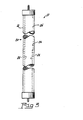
- Fig. 1 is an elevation view of an embodiment of the invention
- Fig. 2 is a sectional view taken along the line 2-2 of Fig. 1 ;
- Fig. 3 is a sectional view taken along the line 3-3 of Fig. 1 .
- a low-pressure fluorescent lamp 10 that includes an elongated, tubular glass envelope 12 including an arc generating and sustaining medium 14 and having electrodes 16 (only one of which is shown) therewithin and having a first section 18 and a second section 20.
- the glass envelope is preferably a soda-lime glass having a transmission of 65% at 313 nm with no more than a 2.5% transmission at 280 nm.
- a phosphor coating 22 is provided on the interior of the first section 18 and on only a portion of the second section 20.
- the phosphor coating comprises materials emitting in the UVA and UVB areas of the electromagnetic spectrum and additionally in the visible area of the electromagnetic spectrum in the range above 600 nm for reasons that will be explained below. Because the phosphor coating 22 exists only on a portion of the second section 20 a clear window 26 is provided (see Fig. 3 ).
- the phosphor coating 22 comprises a mixture of about 91% BaSi 2 O 5 :Pb (which emits in the UVA region of the spectrum; i.e., 320-400 nm); about 6% MgSrAl 10 O 17 :Ce (which emits in the UVB region of the spectrum; i.e., 260-320 nm); and about 3% Y 2 O 3 :Eu (which emits in the visible, red region of the spectrum, preferably above 600 nm).
- the clear window 26 extends about 30° to 45° of the circumference of said envelope 12, which is preferably a T12 diameter (1 and 1 ⁇ 2 inches).
- the low pressure fluorescent lamp 10 has a given length L which preferably is from about 72 to about 80 inches and the clear window 26 extends from one end of said lamp for a distance A which is less than L and preferably is about 1 ⁇ 4 of the given length L, i.e., about 18 to 20 inches.
- a lamp employing the phosphors described above has a buffer gas of argon at a pressure of between 2.0 and 2.5 Torr and sufficient mercury to ensure good operation.
- the length is the afore-mentioned 72 to 80 inches.
- the clear window 26 is formed by removing a like portion of the phosphor coating and extends a width of ⁇ 0.5 to 0.6 inches about the circumference, which exposes to view the phosphor-coated surface opposite the window.
- the clear window 26 would be subject to solarization from the UVC radiation generated by the discharge and would be vulnerable to chemical reactions between the mercury and sodium contained in the glass envelope 12, it is preferable to protect this clear area 26 with a metal oxide coating 28, such as an aluminum oxide coating about 0.8 to 1.2 mg/cm 2 thick.
- the clear window 26 opens a view to the mercury gas discharge during lamp operation and it is this open view of the discharge combined with the transmission characteristics of the glass envelope 12 that allows this second section 20 of the lamp to exhibit higher UVB radiance than the first section 18.
- the addition of the visible light emitting phosphor to the predominantly UV phosphor bend imparts a reddish/pink coloration to the emission throughout the general body of the lamp 10.
- the clear window 26, because it gives visual access to the arc discharge, has a contrasting bluish-white appearance arising from the fact that the Hg-Ar arc exhibits radiance in the blue region of the spectrum.
- an enhanced fluorescent tanning lamp that provides additional radiation for the facial features and additionally provides an improved appearance.
Landscapes
- Chemical & Material Sciences (AREA)
- Inorganic Chemistry (AREA)
- Engineering & Computer Science (AREA)
- Materials Engineering (AREA)
- Organic Chemistry (AREA)
- Vessels And Coating Films For Discharge Lamps (AREA)
Abstract
Description
- TECHNICAL FIELD
- This invention relates to fluorescent lamps and more particularly to fluorescent lamps employed for indoor tanning.
- BACKGROUND ART
- Tanning lamps are known commodities and have been employed for some time in tanning booths and tanning beds. It has been a problem to provide even tanning where the facial features are concerned because of the higher levels of melanin pigments in the face, resulting from more frequent exposure to the sun than the rest of the body. Prior attempts at correcting this problem have used additional lamps in the face area; high pressure UV lamps; lamps with multiple areas of differing phosphors to provided differing radiation zones; and lamps with specialized grooves farmed in the head-end of the lamp.
- These processes have been complicated and expensive. Thus, there is a continuing need for discharge lamps for use in tanning facilities that provide enhanced performance.
- DISCLOSURE OF INVENTION
- It is, therefore, an object of the invention to obviate the disadvantages of the prior art.
- It is another object of the invention to improve tanning lamps.
- It is another object of the invention to enhance the tanning operation.
- These objects are accomplished, in one aspect of the invention, by the provision of a low pressure fluorescent tanning lamp comprising: an elongated, tubular glass envelope including an arc generating and sustaining medium therewithin and having a first section and a second section; a phosphor coating on the interior of said first section and a phosphor coating on only a portion of said second section, said phosphor coating comprising materials emitting in the UVA and UVB areas of the electromagnetic spectrum and additionally in the visible area of the electromagnetic spectrum in the range above 600 nm. In a preferred embodiment of the invention the second section includes a clear window.
- This lamp provides clear advantages over those of the prior art. It is simple to manufacture, utilizing only techniques that have long been used in the making of conventional fluorescent lamps. The application of the clear window allows increased radiation in a desired area by employing conventional envelopes without the necessity of additional glass forming. Further, it eliminates the need for additional high pressure lamps.
- BRIEF DESCRIPTION OF THE DRAWINGS
-
Fig. 1 is an elevation view of an embodiment of the invention; -
Fig. 2 is a sectional view taken along the line 2-2 ofFig. 1 ; and -
Fig. 3 is a sectional view taken along the line 3-3 ofFig. 1 . - BEST MODE FOR CARRYING OUT THE INVENTION
- For a better understanding of the present invention, together with other and further objects, advantages and capabilities thereof, reference is made to the following disclosure and appended claims taken in conjunction with the above-described drawings.
- Referring now to the drawings with greater particularity, there is shown in
Figs. 1 and 2 a low-pressurefluorescent lamp 10 that includes an elongated,tubular glass envelope 12 including an arc generating and sustaining medium 14 and having electrodes 16 (only one of which is shown) therewithin and having afirst section 18 and asecond section 20. The glass envelope is preferably a soda-lime glass having a transmission of 65% at 313 nm with no more than a 2.5% transmission at 280 nm. Aphosphor coating 22 is provided on the interior of thefirst section 18 and on only a portion of thesecond section 20. The phosphor coating comprises materials emitting in the UVA and UVB areas of the electromagnetic spectrum and additionally in the visible area of the electromagnetic spectrum in the range above 600 nm for reasons that will be explained below. Because thephosphor coating 22 exists only on a portion of the second section 20 aclear window 26 is provided (seeFig. 3 ). - In a preferred embodiment of the invention the
phosphor coating 22 comprises a mixture of about 91% BaSi2O5:Pb (which emits in the UVA region of the spectrum; i.e., 320-400 nm); about 6% MgSrAl10O17:Ce (which emits in the UVB region of the spectrum; i.e., 260-320 nm); and about 3% Y2O3:Eu (which emits in the visible, red region of the spectrum, preferably above 600 nm). - The
clear window 26 extends about 30° to 45° of the circumference ofsaid envelope 12, which is preferably a T12 diameter (1 and ½ inches). - The low pressure
fluorescent lamp 10 has a given length L which preferably is from about 72 to about 80 inches and theclear window 26 extends from one end of said lamp for a distance A which is less than L and preferably is about ¼ of the given length L, i.e., about 18 to 20 inches. - In a preferred embodiment, a lamp employing the phosphors described above has a buffer gas of argon at a pressure of between 2.0 and 2.5 Torr and sufficient mercury to ensure good operation. The length is the afore-mentioned 72 to 80 inches. The
clear window 26 is formed by removing a like portion of the phosphor coating and extends a width of ∼0.5 to 0.6 inches about the circumference, which exposes to view the phosphor-coated surface opposite the window. Since theclear window 26 would be subject to solarization from the UVC radiation generated by the discharge and would be vulnerable to chemical reactions between the mercury and sodium contained in theglass envelope 12, it is preferable to protect thisclear area 26 with ametal oxide coating 28, such as an aluminum oxide coating about 0.8 to 1.2 mg/cm2 thick. - The
clear window 26 opens a view to the mercury gas discharge during lamp operation and it is this open view of the discharge combined with the transmission characteristics of theglass envelope 12 that allows thissecond section 20 of the lamp to exhibit higher UVB radiance than thefirst section 18. - The addition of the visible light emitting phosphor to the predominantly UV phosphor bend imparts a reddish/pink coloration to the emission throughout the general body of the
lamp 10. Theclear window 26, because it gives visual access to the arc discharge, has a contrasting bluish-white appearance arising from the fact that the Hg-Ar arc exhibits radiance in the blue region of the spectrum. - Thus, there is provided an enhanced fluorescent tanning lamp that provides additional radiation for the facial features and additionally provides an improved appearance.
- While there have been shown and described what are at present considered to be the preferred embodiments of the invention, it will be apparent to those skilled in the art that various changes and modifications can be made herein without departing from the scope of the invention as defined by the appended claims.
Claims (7)
- A low pressure fluorescent tanning lamp comprising:an elongated, tubular glass envelope including an arc generating and sustaining medium therewithin and having a first section and a second section;a phosphor coating on the interior of said first section and a phosphor coating on only a portion of said second section, said phosphor coating comprising materials emitting in the UVA and UVB areas of the electromagnetic spectrum and additionally in the visible area of the electromagnetic spectrum in the range above 600 nm.
- The low pressure fluorescent tanning lamp of Claim 1 wherein said second section includes a clear window.
- The low pressure fluorescent tanning lamp of Claim 2 wherein said phosphor coating comprises about 91% BaSi2O5:Pb; about 6% MgSrAl10O17:Ce; and about 3% Y2O3:Eu.
- The low pressure fluorescent lamp of Claim 2 wherein said clear window extends about 30° to 45° of the circumference of said envelope.
- The low pressure fluorescent lamp of Claim 2 wherein said lamp has a given length L and said clear window extends from one end of said lamp for a distance A which is less than L.
- The low pressure fluorescent lamp of Claim 5 wherein said distance A is about ¼ of said given length L.
- The low pressure fluorescent lamp of Claim 2 wherein said clear window is covered by an optically transparent metal oxide coating.
Applications Claiming Priority (1)
| Application Number | Priority Date | Filing Date | Title |
|---|---|---|---|
| US12/231,011 US8004170B2 (en) | 2008-08-28 | 2008-08-28 | Tanning lamp |
Publications (2)
| Publication Number | Publication Date |
|---|---|
| EP2159823A2 true EP2159823A2 (en) | 2010-03-03 |
| EP2159823A3 EP2159823A3 (en) | 2011-09-14 |
Family
ID=41353787
Family Applications (1)
| Application Number | Title | Priority Date | Filing Date |
|---|---|---|---|
| EP09010863A Withdrawn EP2159823A3 (en) | 2008-08-28 | 2009-08-25 | Tanning lamp |
Country Status (2)
| Country | Link |
|---|---|
| US (1) | US8004170B2 (en) |
| EP (1) | EP2159823A3 (en) |
Family Cites Families (15)
| Publication number | Priority date | Publication date | Assignee | Title |
|---|---|---|---|---|
| US3717781A (en) * | 1969-09-19 | 1973-02-20 | Sylvania Electric Prod | Aperture fluorescent lamp having uniform surface brightness |
| US3988633A (en) | 1975-01-30 | 1976-10-26 | Duro-Test Corporation | Fluorescent lamp with envelope grooves |
| US3988663A (en) * | 1975-03-19 | 1976-10-26 | Texaco Inc. | Locator for metallic pipe with AC signals impressed |
| US3987331A (en) * | 1975-03-24 | 1976-10-19 | Gte Sylvania Incorporated | Ultraviolet emitting fluorescent lamp having internal reflector film |
| US4678966A (en) * | 1980-06-13 | 1987-07-07 | Gte Products Corporation | Fluorescent lamp having two phosphor layers |
| DE3422605A1 (en) * | 1984-06-18 | 1985-12-19 | Friedrich 7800 Freiburg Wolff | DEVICE FOR FULL BODY RADIATION |
| US4825125A (en) * | 1984-12-06 | 1989-04-25 | Gte Products Corporation | Discharge lamp having multiple constrictions |
| US4924141A (en) * | 1986-11-12 | 1990-05-08 | Gte Products Corporation | Aluminum oxide reflector layer for fluorescent lamps |
| US5216323A (en) * | 1990-03-21 | 1993-06-01 | U.S. Philips Corporation | Low-pressure mercury vapor discharge lamp for suntanning purposes |
| US5234710A (en) * | 1991-12-13 | 1993-08-10 | Gte Products Corporation | Fluorescent suntanning lamps |
| US5565685A (en) * | 1995-07-21 | 1996-10-15 | Light Sources, Inc. | Dual intensity ultraviolet lamp |
| US5557112A (en) * | 1995-07-21 | 1996-09-17 | Light Sources, Inc. | Dual radiation ultraviolet lamp |
| US6777702B2 (en) * | 2002-02-15 | 2004-08-17 | Voltarc Technologies, Inc. | Discharge lamp having multiple intensity regions |
| US6943361B2 (en) * | 2002-02-15 | 2005-09-13 | Voltarc Technologies Inc. | Tanning lamp having grooved periphery |
| DE10231257A1 (en) * | 2002-07-11 | 2004-01-22 | Philips Intellectual Property & Standards Gmbh | tanning device |
-
2008
- 2008-08-28 US US12/231,011 patent/US8004170B2/en not_active Expired - Fee Related
-
2009
- 2009-08-25 EP EP09010863A patent/EP2159823A3/en not_active Withdrawn
Non-Patent Citations (1)
| Title |
|---|
| None |
Also Published As
| Publication number | Publication date |
|---|---|
| US20100052505A1 (en) | 2010-03-04 |
| US8004170B2 (en) | 2011-08-23 |
| EP2159823A3 (en) | 2011-09-14 |
Similar Documents
| Publication | Publication Date | Title |
|---|---|---|
| US6787979B2 (en) | Rare-gas low-pressure discharge lamp, method of manufacturing a rare-gas low-pressure discharge lamp, and application of a gas discharge lamp | |
| US20110309738A1 (en) | Enhanced uv-emitting fluorescent lamp | |
| TW201017713A (en) | Ultra-violet and visible light emitting system | |
| JPH02299146A (en) | Low pressure mercury vapor discharge lamp | |
| EP1588395B1 (en) | Uv-emitting phosphor blend | |
| CN101447389A (en) | Improved insect attraction light source | |
| US7435358B2 (en) | UVC-emitting Sr(Al,Mg)12O19:Pr phosphor and lamp containing same | |
| US6952081B1 (en) | Fluorescent lamp having ultraviolet reflecting layer | |
| US8004170B2 (en) | Tanning lamp | |
| US6781302B2 (en) | Low pressure mercury vapor fluorescent lamps | |
| JP2007520042A (en) | Low pressure mercury vapor fluorescent lamp | |
| CN1992146B (en) | Dielectric barrier discharge lamp | |
| JP2003109541A (en) | UV fluorescent lamp | |
| JP2009537941A (en) | Low pressure gas discharge lamp with improved efficiency | |
| JP2002358926A (en) | UV fluorescent lamp | |
| JP2003272559A (en) | Fluorescent lamp | |
| US7825598B2 (en) | Mercury-free discharge compositions and lamps incorporating Titanium, Zirconium, and Hafnium | |
| CN101258222A (en) | UV lamps for treating skin | |
| JPH09213276A (en) | Metal halide lamp | |
| JPH10241631A (en) | Fluorescent lamp | |
| US20130076226A1 (en) | Fluorescent lamp with zinc silicate phosphor and protective phosphor layer | |
| JP2004220984A (en) | Fluorescent lamp | |
| JPH10241634A (en) | Electrodeless fluorescent lamp | |
| US20080224591A1 (en) | Low-Pressure Mercury Discharge Lamp and Process for Its Preparation | |
| JP2009535772A (en) | Low pressure discharge lamp |
Legal Events
| Date | Code | Title | Description |
|---|---|---|---|
| PUAI | Public reference made under article 153(3) epc to a published international application that has entered the european phase |
Free format text: ORIGINAL CODE: 0009012 |
|
| AK | Designated contracting states |
Kind code of ref document: A2 Designated state(s): AT BE BG CH CY CZ DE DK EE ES FI FR GB GR HR HU IE IS IT LI LT LU LV MC MK MT NL NO PL PT RO SE SI SK SM TR |
|
| AX | Request for extension of the european patent |
Extension state: AL BA RS |
|
| RAP1 | Party data changed (applicant data changed or rights of an application transferred) |
Owner name: NARVA LICHTQUELLEN GMBH & CO KG |
|
| PUAL | Search report despatched |
Free format text: ORIGINAL CODE: 0009013 |
|
| AK | Designated contracting states |
Kind code of ref document: A3 Designated state(s): AT BE BG CH CY CZ DE DK EE ES FI FR GB GR HR HU IE IS IT LI LT LU LV MC MK MT NL NO PL PT RO SE SI SK SM TR |
|
| AX | Request for extension of the european patent |
Extension state: AL BA RS |
|
| RIC1 | Information provided on ipc code assigned before grant |
Ipc: H01J 61/35 20060101ALI20110809BHEP Ipc: H01J 61/44 20060101AFI20110809BHEP |
|
| STAA | Information on the status of an ep patent application or granted ep patent |
Free format text: STATUS: THE APPLICATION IS DEEMED TO BE WITHDRAWN |
|
| 18D | Application deemed to be withdrawn |
Effective date: 20120301 |