EP2159819A2 - Plasma generator - Google Patents
Plasma generator Download PDFInfo
- Publication number
- EP2159819A2 EP2159819A2 EP09151534A EP09151534A EP2159819A2 EP 2159819 A2 EP2159819 A2 EP 2159819A2 EP 09151534 A EP09151534 A EP 09151534A EP 09151534 A EP09151534 A EP 09151534A EP 2159819 A2 EP2159819 A2 EP 2159819A2
- Authority
- EP
- European Patent Office
- Prior art keywords
- coaxial cable
- microwave
- plasma generator
- conductor
- inner conductor
- Prior art date
- Legal status (The legal status is an assumption and is not a legal conclusion. Google has not performed a legal analysis and makes no representation as to the accuracy of the status listed.)
- Granted
Links
Images



Classifications
-
- H—ELECTRICITY
- H01—ELECTRIC ELEMENTS
- H01J—ELECTRIC DISCHARGE TUBES OR DISCHARGE LAMPS
- H01J37/00—Discharge tubes with provision for introducing objects or material to be exposed to the discharge, e.g. for the purpose of examination or processing thereof
- H01J37/32—Gas-filled discharge tubes
- H01J37/32009—Arrangements for generation of plasma specially adapted for examination or treatment of objects, e.g. plasma sources
- H01J37/32192—Microwave generated discharge
- H01J37/32211—Means for coupling power to the plasma
-
- A—HUMAN NECESSITIES
- A61—MEDICAL OR VETERINARY SCIENCE; HYGIENE
- A61B—DIAGNOSIS; SURGERY; IDENTIFICATION
- A61B18/00—Surgical instruments, devices or methods for transferring non-mechanical forms of energy to or from the body
- A61B18/04—Surgical instruments, devices or methods for transferring non-mechanical forms of energy to or from the body by heating
- A61B18/042—Surgical instruments, devices or methods for transferring non-mechanical forms of energy to or from the body by heating using additional gas becoming plasma
-
- H—ELECTRICITY
- H01—ELECTRIC ELEMENTS
- H01J—ELECTRIC DISCHARGE TUBES OR DISCHARGE LAMPS
- H01J37/00—Discharge tubes with provision for introducing objects or material to be exposed to the discharge, e.g. for the purpose of examination or processing thereof
- H01J37/32—Gas-filled discharge tubes
- H01J37/32009—Arrangements for generation of plasma specially adapted for examination or treatment of objects, e.g. plasma sources
- H01J37/32192—Microwave generated discharge
-
- H—ELECTRICITY
- H01—ELECTRIC ELEMENTS
- H01J—ELECTRIC DISCHARGE TUBES OR DISCHARGE LAMPS
- H01J37/00—Discharge tubes with provision for introducing objects or material to be exposed to the discharge, e.g. for the purpose of examination or processing thereof
- H01J37/32—Gas-filled discharge tubes
- H01J37/32009—Arrangements for generation of plasma specially adapted for examination or treatment of objects, e.g. plasma sources
- H01J37/32192—Microwave generated discharge
- H01J37/32211—Means for coupling power to the plasma
- H01J37/32247—Resonators
-
- H—ELECTRICITY
- H05—ELECTRIC TECHNIQUES NOT OTHERWISE PROVIDED FOR
- H05H—PLASMA TECHNIQUE; PRODUCTION OF ACCELERATED ELECTRICALLY-CHARGED PARTICLES OR OF NEUTRONS; PRODUCTION OR ACCELERATION OF NEUTRAL MOLECULAR OR ATOMIC BEAMS
- H05H1/00—Generating plasma; Handling plasma
- H05H1/24—Generating plasma
- H05H1/26—Plasma torches
- H05H1/30—Plasma torches using applied electromagnetic fields, e.g. high frequency or microwave energy
-
- H—ELECTRICITY
- H05—ELECTRIC TECHNIQUES NOT OTHERWISE PROVIDED FOR
- H05H—PLASMA TECHNIQUE; PRODUCTION OF ACCELERATED ELECTRICALLY-CHARGED PARTICLES OR OF NEUTRONS; PRODUCTION OR ACCELERATION OF NEUTRAL MOLECULAR OR ATOMIC BEAMS
- H05H1/00—Generating plasma; Handling plasma
- H05H1/24—Generating plasma
- H05H1/46—Generating plasma using applied electromagnetic fields, e.g. high frequency or microwave energy
-
- H—ELECTRICITY
- H05—ELECTRIC TECHNIQUES NOT OTHERWISE PROVIDED FOR
- H05H—PLASMA TECHNIQUE; PRODUCTION OF ACCELERATED ELECTRICALLY-CHARGED PARTICLES OR OF NEUTRONS; PRODUCTION OR ACCELERATION OF NEUTRAL MOLECULAR OR ATOMIC BEAMS
- H05H1/00—Generating plasma; Handling plasma
- H05H1/24—Generating plasma
- H05H1/46—Generating plasma using applied electromagnetic fields, e.g. high frequency or microwave energy
- H05H1/461—Microwave discharges
- H05H1/4637—Microwave discharges using cables
Definitions
- the present invention relates to the field of plasma generation.
- Embodiments relate to a small-sized microwave plasma generator capable of generating plasma with low electric power, for example a portable generator.
- a plasma torch is a device that generates a directed flow of plasma from its nozzle.
- the plasma jet can be used to melt a solid, or evaporate a solid or a liquid, or heat a gas to increase enthalpy in a closed thermodynamic system under constant and entropy.
- a conventional microwave plasma generator usually equipped with a magnetron, consumes more than 100 watts to operate.
- a conventional microwave plasma generator equipped with a rectangular waveguide, is too bulky to carry.
- a coaxial microwave plasma torch equipped with an antenna-shaped discharge tube may substitute for the conventional microwave plasma generator, but is also too large-sized to carry.
- a conventional microwave plasma generator is currently in use which generates plasma at atmospheric pressure, using various types of electric power sources.
- a great deal of research has gone into developing a microwave plasma generator which generates plasma without thermal effect with low electric power by using a microwaves with a frequency of 900 MHz or 2.45 GHz.
- Embodiments aim to provide a small-sized portable microwave plasma generator capable of generating plasma at atmospheric pressure with low electric power.
- a portable microwave plasma generator capable of generating plasma with low electric power.
- a coaxial cable includes a first inner conductor and a dielectric material encircling the first inner conductor.
- the outer conductor encircles the coaxial cable.
- the connection conductor includes at least one gas inlet tube.
- the connection conductor electrically connects between the first inner conductor and the outer conductor at one end of the coaxial cable.
- the connection member includes a second inner conductor passing through the outer conductor and then connecting to the first inner conductor.
- the microwave plasma generator is less than 10 cm in length and generates plasma at atmospheric pressure with low electric power. In an embodiment, the microwave plasma generator is capable of matching its impedance with impedance of a microwave oscillator supplying a microwave without having to use a separate impedance matching device.
- a portable microwave plasma generator 100 includes a coaxial cable 10, an outer conductor 4, a connection conductor 2, a connection member 1, and a discharge tip 5.
- the coaxial cable 10 includes a first inner conductor 7 and a dielectric material 6 encircling the first inner conductor 7.
- the outer conductor encircles the coaxial cable 10.
- the connection conductor 2 includes at least one gas inlet tube 3.
- the connection conductor 2 electrically connects between the first inner conductor 7 and the outer conductor 4 at one end of the coaxial cable 10.
- the connection member 1 includes a second inner conductor 8 passing through the outer conductor 4 and then electrically connects to the first inner conductor 7 at a feeding point 9.
- the connection member 1 is conductive.
- An insulating material may be provided between the second inner conductor 8 and the connection member 1.
- the discharge tip 5, provided on the other end of the coaxial cable 10, serves to minimize electric power consumption when generating plasma on the coaxial cable 10.
- the portable microwave plasma generator 100 generates plasma using resonance energy of a microwave with a frequency of 900 MHz or 2.45 GHz which is applied through the second inner conductor 8,
- the connection member 1, the connection conductor 2, the outer conductor 4, the first inner conductor 7, and the second inner conductor 8 electrically connects to each other and function as a resonator oscillating the microwave.
- the microwave converts into a TEM (Transverse Electro-Magnetic) wave in the coaxial cable 10,
- the TEM wave is a transverse wave, carrying electromagnetic energy, which has not an electric field component and a magnetic field component in the propagation direction, but has the electric field component and the magnetic field component in the direction perpendicular (transverse) to the propagation direction.
- Air is used as the dielectric material 6 between an outer jacket of the coaxial cable 10 and the first inner conductor 7. That is, the dielectric 6 is an empty space into which an inert gas is introduced to be ionized.
- the introduced gas becomes in a state of plasma by resonance energy of the microwave resonating and amplified on the conductors 2, 4, 7, and 8 to which the microwave is applied, and discharges toward the bottom of the portable microwave plasma generator, i.e., in the direction B.
- Other materials such as a fluorocarbon solid (for example PTFE) may be used as the dielectric material 6.
- a length of the coaxial cable 10 may be 1/4 (one-third) or 3/4 (three-quarters) of a wavelength of the microwave which is suitable for the microwave to produce resonance.
- the length of the coaxial cable 10 is set to this length, the electric field strength becomes maximized at the end of the resonator which is in the direction B, thereby generating plasma more easily.
- ⁇ C f ⁇ ⁇
- A is a wavelength of the microwave
- C is a speed of light
- f is a frequency of the microwave
- ⁇ r is a relative dielectric constant.
- the relative dielectric constant is 1 (one) when the dielectric material is an air and is 2.1 when the dielectric material is PTFE.
- the frequency of the microwave is 900MHz
- the length ⁇ of the microwave is expressed as the following equation 2.
- 1/4 (one-quarter) of the microwave is approximately 8.33 cm. This makes it possible to manufacture the portable microwave plasma generator which is around 10cm in length.
- An input impedance of the coaxial cable 10 seen from the feeding point 9 where the first inner conductor 7 of the coaxial 10 and the second inner conductor 8 of the connection member 1 come in contact with each other varies depending upon a position of the feeding point 9,
- the impedance matching can easily be made between a microwave oscillator (not shown) applying the microwave to the coaxial cable 10 through the second inner conductor 8 and the microwave plasma generator or between an amplifier amplifying the microwave outputting from the microwave oscillator and the microwave plasma generator, This is later described in more detail.
- the discharge tip 5 is used to locally increase the electric field strength.
- the discharge tip 5 does not need to be used, after discharge occurs and plasma is generated.
- the discharge tip 5, when not in use, may be removed from the microwave plasma generator.
- Experimental findings show that an embodiment of the portable microwave plasma generator can generate plasma with about 1 watt or so.
- connection conductor 2 is inserted into the middle of the outer conductor 4.
- two gas inlet tubes 3, through which the inert gas is introduced into the dielectric material 6, are provided to the connection conductor 2.
- the single inlet tube 3 may be provided to the connection conductor 2.
- the inert gas includes helium and argon.
- the outer conductor 4 encircles the coaxial cable 10 which has the first inner conductor 7 at the center, and the dielectric material 6 is provided between the outer jacket of the coaxial cable 10 and the first inner conductor 7.
- the discharge tip 5 is positioned on the end of the coaxial cable 10, which is in the direction B. The discharge tip 5 discharges plasma outputting in the direction B.
- a coaxial cable extension tab 11, oval-shaped part (marked dotted line) in the middie of the portable microwave plasma generator 400 serves to adjust the length of the outer conductor 4 of the coaxial cable and the length of the first inner conductor 7 of the coaxial cable.
- the outer conductor 4 of the coaxial cable 10 and the first inner conductor 7 of the coaxial cable 10 may be expandable or contractable in a slidable manner or in an attachable and detachable manner to adjust the length of the coaxial cable 10. Adjustment of the length of the coaxial cable 10 with the coaxial cable extension tab 11 makes it possible not only to effectively produce resonance, but also to make the impedance matching which prevents the microwave from being reflected.
- the lower part of the coaxial cable 10 and the upper part of the coaxial part including the extension tab 11 may attach to or detach from each other. This makes it possible to replace of the coaxial cable 10 including the extension tab 11, when the end of the resonator is eroded away by plasma, thereby extending the life of the microwave plasma generator.
- An embodiment of the portable microwave plasma generator capable of generating plasma with low electric power can adjust its impedance by adjusting the position of the connection member 1. This removes the need for installing the impedance match device to make the impedance matching between the microwave oscillator (not shown) applying the microwave to the coaxial cable 10 through the second inner conductor 8 and the microwave p!asma generator or between an amplifier amplifying the microwave outputting from the microwave oscillator and the microwave plasma generator.
- the input impedance Z IN of the coaxial cable 10 seen from the feeding point 9 where the first inner conductor 7 of the coaxial cable 10 and the second inner conductor 8 of the connection member 1 come in contact with each other is expressed as the following equation 3.
- Z 0 is a characteristic impedance of the coaxial cable
- j is a complex number - 1 .
- I 1 is a distance between the feeding point 9 and the left end of the coaxial cable
- I 2 is a distance between the feeding point 9 and the right end of the coaxial cable
- k is a complex propagation constant or a wave number which is a reciprocal number of wavelength
- ⁇ is an attenuation constant of the coaxial cable
- ⁇ is a phase constant of the coaxial cable 10.
- the left end of the coaxial cable 10 connects to the connection conductor 2, so a load impedance Z 1 , of the first impedance Z 1 is 0 (zero),
- the right end of the coaxial cable 10 opens, so the load impedance is ⁇ (infinite).
- the attenuation constant ⁇ of the coaxial cable 10, and the phase constant ⁇ of the coaxial cable 10 are constants which are automatically determined by the electric characteristics of the coaxial cable 10, So, the input impedance Z IN i.e., the input impedance Z IN of the resonator is determined by I 1 and I 2 .
- the resonator corresponds to what consists of the resistor, the inductor, and the capacitor which connect in parallel to each other.
- the position of the feeding point 9 is determined by adjusting any one of I 1 and I 2 .
- the length of the coaxial cable 10 in the portable microwave plasma generator is 1/4 (one-quarter) of wavelength of the microwave.
- a SMA (Sub Miniature version A) connector is used as the connection member 1.
- FIG.7 is a front view of the right end F of the portable microwave plasma generator capable of generating plasma with low electric power, as shown in FIG.6 .
- the gap is 40 ⁇ m. If the portable microwave plasma generator makes resonance using the microwave with a frequency of 2.45 GHz and the length of the coaxial cable 10 is 3/4 (three-quarters) of the wavelength of the microwave, then the gap is 100 ⁇ m.
- the inert gas is introduced into the gas inlet tube 3.
- the coaxial cable 100 designed for the specific purpose is employed in the portable microwave plasma generator according to the present invention.
- a general type of the semi rigid coaxial cable in wide use may be instead employed.
- the voltage and the electromagnetic field become at a maximum at the end of the resonator, i.e, at the end of the portable microwave plasma generator.
- the portable microwave plasma generator effectively generates plasma, using electric power at a minimum, compared with the conventional microwave plasma generator.
- the length of the portable microwave plasma generator is made to be 10 cm or so that corresponds to one-quarter of the wavelength of the microwave. This makes portable the portable microwave plasma generator.
- the portable microwave plasma generator does not require the installation of separate impedance matching device, if the impedance of the resonator is adjusted to 50 ⁇ , the output impedance of the microwave oscillator.
Landscapes
- Physics & Mathematics (AREA)
- Engineering & Computer Science (AREA)
- Plasma & Fusion (AREA)
- Chemical & Material Sciences (AREA)
- Analytical Chemistry (AREA)
- Health & Medical Sciences (AREA)
- Electromagnetism (AREA)
- Spectroscopy & Molecular Physics (AREA)
- Surgery (AREA)
- Life Sciences & Earth Sciences (AREA)
- Molecular Biology (AREA)
- Nuclear Medicine, Radiotherapy & Molecular Imaging (AREA)
- Biomedical Technology (AREA)
- Heart & Thoracic Surgery (AREA)
- Medical Informatics (AREA)
- Otolaryngology (AREA)
- Animal Behavior & Ethology (AREA)
- General Health & Medical Sciences (AREA)
- Public Health (AREA)
- Veterinary Medicine (AREA)
- Plasma Technology (AREA)
- Constitution Of High-Frequency Heating (AREA)
Abstract
Description
- The present invention relates to the field of plasma generation. Embodiments relate to a small-sized microwave plasma generator capable of generating plasma with low electric power, for example a portable generator.
- A plasma torch is a device that generates a directed flow of plasma from its nozzle. The plasma jet can be used to melt a solid, or evaporate a solid or a liquid, or heat a gas to increase enthalpy in a closed thermodynamic system under constant and entropy.
- A conventional microwave plasma generator, usually equipped with a magnetron, consumes more than 100 watts to operate. A conventional microwave plasma generator, equipped with a rectangular waveguide, is too bulky to carry. A coaxial microwave plasma torch, equipped with an antenna-shaped discharge tube may substitute for the conventional microwave plasma generator, but is also too large-sized to carry.
- A conventional microwave plasma generator is currently in use which generates plasma at atmospheric pressure, using various types of electric power sources. A great deal of research has gone into developing a microwave plasma generator which generates plasma without thermal effect with low electric power by using a microwaves with a frequency of 900 MHz or 2.45 GHz.
- Worldwide research has been done on application of plasma to the biomedical field, The U.S. FDA approved the use of the microwave plasma generator in medical treatment of wrinkles and speckles on the human skin. Development of a portable microwave plasma generator consuming less than 5 watts at atmospheric pressure will expand its application to cancer treatment, dental care, cosmetic treatment, disinfection, coagulation, sterilization, air purification, and so forth,
- Embodiments aim to provide a small-sized portable microwave plasma generator capable of generating plasma at atmospheric pressure with low electric power.
- According to one aspect there is provided a portable microwave plasma generator capable of generating plasma with low electric power. Including a coaxial cable, an outer conductor, a connection conductor; and a connection member. The coaxial cable includes a first inner conductor and a dielectric material encircling the first inner conductor. The outer conductor encircles the coaxial cable. The connection conductor includes at least one gas inlet tube. The connection conductor electrically connects between the first inner conductor and the outer conductor at one end of the coaxial cable. The connection member includes a second inner conductor passing through the outer conductor and then connecting to the first inner conductor.
- In an embodiment, the microwave plasma generator is less than 10 cm in length and generates plasma at atmospheric pressure with low electric power. In an embodiment, the microwave plasma generator is capable of matching its impedance with impedance of a microwave oscillator supplying a microwave without having to use a separate impedance matching device.
- An embodiment of the invention will be described with reference to the accompanying drawings, in which:
-
FIG. 1 is a cross-sectional view of a portable microwave plasma generator capable of generating plasma with low electric power; -
FIG.2 is a front view of the A direction end of the portable microwave plasma generator capable of generating plasma with low electric power, as shown inFIG.1 ; -
FIG.3 is a front view of the B direction end of the portable microwave plasma generator capable of generating plasma with low electric power, as shown inFIG.1 ; -
FIG.4 is a view of the portable microwave plasma generator capable of generating plasma with low electric power, having the coaxial cable whose the length is adjustable; -
FIG.5 is a schematic view of the portable microwave plasma generator capable of generating plasma with low electric power; -
FIG.6 is a picture of an actual product embodying the portable microwave plasma generator capable of generating plasma with low electric power; -
FIG.7 is a front view of the right end F of the portable microwave plasma generator capable of generating plasma with low electric power, as shown inFIG.6 ; and -
FIG.8 is a front view of the left end R of the portable microwave plasma generator capable of generating plasma with low electric power, as shown inFIG.6 . - Referring to
FIG.1 a portable microwave plasma generator 100 includes acoaxial cable 10, anouter conductor 4, aconnection conductor 2, a connection member 1, and adischarge tip 5. - The
coaxial cable 10 includes a firstinner conductor 7 and adielectric material 6 encircling the firstinner conductor 7. The outer conductor encircles thecoaxial cable 10. Theconnection conductor 2 includes at least onegas inlet tube 3. Theconnection conductor 2 electrically connects between the firstinner conductor 7 and theouter conductor 4 at one end of thecoaxial cable 10. The connection member 1 includes a second inner conductor 8 passing through theouter conductor 4 and then electrically connects to the firstinner conductor 7 at a feeding point 9. The connection member 1 is conductive. An insulating material may be provided between the second inner conductor 8 and the connection member 1. Thedischarge tip 5, provided on the other end of thecoaxial cable 10, serves to minimize electric power consumption when generating plasma on thecoaxial cable 10. - The portable microwave plasma generator 100 generates plasma using resonance energy of a microwave with a frequency of 900 MHz or 2.45 GHz which is applied through the second inner conductor 8, The connection member 1, the
connection conductor 2, theouter conductor 4, the firstinner conductor 7, and the second inner conductor 8 electrically connects to each other and function as a resonator oscillating the microwave. The microwave converts into a TEM (Transverse Electro-Magnetic) wave in thecoaxial cable 10, The TEM wave is a transverse wave, carrying electromagnetic energy, which has not an electric field component and a magnetic field component in the propagation direction, but has the electric field component and the magnetic field component in the direction perpendicular (transverse) to the propagation direction. - Air is used as the
dielectric material 6 between an outer jacket of thecoaxial cable 10 and the firstinner conductor 7. That is, the dielectric 6 is an empty space into which an inert gas is introduced to be ionized. The introduced gas becomes in a state of plasma by resonance energy of the microwave resonating and amplified on theconductors dielectric material 6. - A length of the
coaxial cable 10 may be 1/4 (one-third) or 3/4 (three-quarters) of a wavelength of the microwave which is suitable for the microwave to produce resonance. When the length of thecoaxial cable 10 is set to this length, the electric field strength becomes maximized at the end of the resonator which is in the direction B, thereby generating plasma more easily. - The relation between a speed of light, a frequency and a length of the microwave is expressed as the following equation. 1.

where A is a wavelength of the microwave, C is a speed of light, f is a frequency of the microwave, and εr is a relative dielectric constant. The relative dielectric constant is 1 (one) when the dielectric material is an air and is 2.1 when the dielectric material is PTFE. - For example, the frequency of the microwave is 900MHz, the length λ of the microwave is expressed as the following
equation 2.
- According to the
equation 2, 1/4 (one-quarter) of the microwave is approximately 8.33 cm. This makes it possible to manufacture the portable microwave plasma generator which is around 10cm in length. - An input impedance of the
coaxial cable 10 seen from the feeding point 9 where the firstinner conductor 7 of the coaxial 10 and the second inner conductor 8 of the connection member 1 come in contact with each other varies depending upon a position of the feeding point 9, By adjusting the position of the feeding point 9, the impedance matching can easily be made between a microwave oscillator (not shown) applying the microwave to thecoaxial cable 10 through the second inner conductor 8 and the microwave plasma generator or between an amplifier amplifying the microwave outputting from the microwave oscillator and the microwave plasma generator, This is later described in more detail. - Generation of plasma at atmospheric pressure requires high electric field strength of 106 V/m (Volts/meter) or more. The
discharge tip 5 is used to locally increase the electric field strength. Thedischarge tip 5 does not need to be used, after discharge occurs and plasma is generated. Thedischarge tip 5, when not in use, may be removed from the microwave plasma generator. Experimental findings show that an embodiment of the portable microwave plasma generator can generate plasma with about 1 watt or so. - As shown in
FIG.2 , theconnection conductor 2 is inserted into the middle of theouter conductor 4. And the twogas inlet tubes 3, through which the inert gas is introduced into thedielectric material 6, are provided to theconnection conductor 2. Thesingle inlet tube 3 may be provided to theconnection conductor 2. The inert gas includes helium and argon. - As shown in
FIG.3 , theouter conductor 4 encircles thecoaxial cable 10 which has the firstinner conductor 7 at the center, and thedielectric material 6 is provided between the outer jacket of thecoaxial cable 10 and the firstinner conductor 7. Thedischarge tip 5 is positioned on the end of thecoaxial cable 10, which is in the direction B. Thedischarge tip 5 discharges plasma outputting in the direction B. - As shown in FGI.4, a coaxial
cable extension tab 11, oval-shaped part (marked dotted line) in the middie of the portable microwave plasma generator 400 serves to adjust the length of theouter conductor 4 of the coaxial cable and the length of the firstinner conductor 7 of the coaxial cable. For example, theouter conductor 4 of thecoaxial cable 10 and the firstinner conductor 7 of thecoaxial cable 10 may be expandable or contractable in a slidable manner or in an attachable and detachable manner to adjust the length of thecoaxial cable 10. Adjustment of the length of thecoaxial cable 10 with the coaxialcable extension tab 11 makes it possible not only to effectively produce resonance, but also to make the impedance matching which prevents the microwave from being reflected. The lower part of thecoaxial cable 10 and the upper part of the coaxial part including theextension tab 11 may attach to or detach from each other. This makes it possible to replace of thecoaxial cable 10 including theextension tab 11, when the end of the resonator is eroded away by plasma, thereby extending the life of the microwave plasma generator. - An embodiment of the portable microwave plasma generator capable of generating plasma with low electric power can adjust its impedance by adjusting the position of the connection member 1. This removes the need for installing the impedance match device to make the impedance matching between the microwave oscillator (not shown) applying the microwave to the
coaxial cable 10 through the second inner conductor 8 and the microwave p!asma generator or between an amplifier amplifying the microwave outputting from the microwave oscillator and the microwave plasma generator. - Operation of the portable microwave plasma generator and relation between it and its peripheral devices are now described.
- Referring to
FIG.5 , the input impedance ZIN of thecoaxial cable 10 seen from the feeding point 9 where the firstinner conductor 7 of thecoaxial cable 10 and the second inner conductor 8 of the connection member 1 come in contact with each other is expressed as thefollowing equation 3.
Where the first impedance Z1 is an impedance of thecoaxial cable 10 to the left of the feeding point 9, a second impedance Z2 is an impedance of the coaxial cable to the right of the feeding point 9, Z0 is a characteristic impedance of thecoaxial cable 10, j is a complex number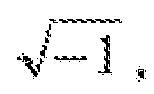
coaxial cable 10, I2 is a distance between the feeding point 9 and the right end of thecoaxial cable 10, k is a complex propagation constant or a wave number which is a reciprocal number of wavelength, α is an attenuation constant of thecoaxial cable 10, and β is a phase constant of thecoaxial cable 10. Theequation 3 is written on the assumption that when (αl)=1(one), tan(αl)≈(αl). - The left end of the
coaxial cable 10 connects to theconnection conductor 2, so a load impedance Z1, of the first impedance Z1 is 0 (zero), The right end of thecoaxial cable 10 opens, so the load impedance is ∞ (infinite). The attenuation constant α of thecoaxial cable 10, and the phase constant β of thecoaxial cable 10 are constants which are automatically determined by the electric characteristics of thecoaxial cable 10, So, the input impedance ZIN i.e., the input impedance ZIN of the resonator is determined by I1 and I2. - When the length of the
coaxial cable 10 is less than 1/4 (one-quarter) of the wavelength of the microwave, adjustment of I1 means adjustment of inductance of the resonator, and adjustment of I2 means adjustment of capacitance of the resonator. So, the resonator corresponds to what consists of the resistor, the inductor, and the capacitor which connect in parallel to each other. Thus, the position of the feeding point 9 is determined by adjusting any one of I1 and I2. When the input impedance ZIN is set to 50Ω(Ohm), the separate impedance matching device does not need to be installed. - This is about the
coaxial cable 10 of which the length is 1/4 (one-quarter) or 3/4 (three-quarters) of the wavelength of the microwave. This may be applied to thecoaxial cable 10 of which the length is any one of multiples of 1/4 (one-quarter) and multiples of 3/4 (three-quarters) of the wavelength of the microwave. - As shown in
FIG.6 , the length of thecoaxial cable 10 in the portable microwave plasma generator is 1/4 (one-quarter) of wavelength of the microwave. A SMA (Sub Miniature version A) connector is used as the connection member 1. -
FIG.7 is a front view of the right end F of the portable microwave plasma generator capable of generating plasma with low electric power, as shown inFIG.6 . - As shown in
FIG.7 , there is a given gap between thedischarge tip 5 and the firstinner conductor 7 at the right end of the portable microwave plasma generator. If the portable microwave plasma generator makes resonance using the microwave with a frequency of 900 MHz and the length of thecoaxial cable 10 is 1/4 (one-quarter) of the wavelength of the microwave, then the gap is 40 µm. If the portable microwave plasma generator makes resonance using the microwave with a frequency of 2.45 GHz and the length of thecoaxial cable 10 is 3/4 (three-quarters) of the wavelength of the microwave, then the gap is 100 µm. - As shown in
FIG.8 , the inert gas is introduced into thegas inlet tube 3. - As above described, the coaxial cable 100 designed for the specific purpose is employed in the portable microwave plasma generator according to the present invention. However, a general type of the semi rigid coaxial cable in wide use may be instead employed. The voltage and the electromagnetic field become at a maximum at the end of the resonator, i.e, at the end of the portable microwave plasma generator. As a result, the portable microwave plasma generator effectively generates plasma, using electric power at a minimum, compared with the conventional microwave plasma generator. Furthermore, the length of the portable microwave plasma generator is made to be 10 cm or so that corresponds to one-quarter of the wavelength of the microwave. This makes portable the portable microwave plasma generator. The portable microwave plasma generator does not require the installation of separate impedance matching device, if the impedance of the resonator is adjusted to 50 Ω, the output impedance of the microwave oscillator.
- The invention is not restricted to the described embodiments.
Claims (11)
- A microwave plasma generator comprising:a coaxial cable comprising:a first inner conductor; anda dielectric material encircling the first inner conductor;an outer conductor encircling the coaxial cable;a connection conductor, comprising at least one gas inlet tube, electrically connecting between the first inner conductor and the outer conductor at one end of the coaxial cable; anda connection member comprising a second inner conductor passing through the outer conductor and then connecting to the first inner conductor.
- A plasma generator according to claim 1, wherein the dielectric material is air, an empty space into which to introduce an inert gas, and a microwave is applied through the second inner conductor.
- A microwave plasma generator according to claim 2, wherein the inert gas is selected from a group consisting of helium and argon.
- A microwave plasma generator according to claim 2, wherein the microwave has a frequency of 900MHz or 2.45GHz.
- A microwave plasma generator, according to claim 2, wherein a length of the coaxial cable is 1/4 (one-quarter), or 3/4 (three-quarters) of the wavelength of the microwave.
- A microwave plasma generator, according to claim 2, wherein a length of the coaxial cable is any one of multiples of 1/4 (one-quarter) and multiples of 3/4 (three-quarters) of the wavelength of the microwave.
- A microwave plasma generator according to claim 1, wherein the coaxial cable comprises at least two parts which are attachable to and detachable from each other or are slidable into each other in a manner that adjust the length of the coaxial cable.
- A microwave plasma generator according to claim 4, further comprising a discharge tip, provided on the other end of the coaxial cable, for discharging plasma in the coaxial cable.
- A microwave plasma generator according to claim 8, wherein a gap between the discharge tip and the first inner conductor is 40 µm when the microwave has a frequency of 900MHz.
- A microwave plasma generator according to claim 8, wherein a gap between the discharge tip and the first inner conductor is 100 µm when the microwave has a frequency of 2.45GHz.
- A microwave plasma generator according to any preceding claim, wherein the generator is portable.
Applications Claiming Priority (1)
| Application Number | Priority Date | Filing Date | Title |
|---|---|---|---|
| KR1020080083364A KR101012345B1 (en) | 2008-08-26 | 2008-08-26 | Low Power Portable Microwave Plasma Generator |
Publications (3)
| Publication Number | Publication Date |
|---|---|
| EP2159819A2 true EP2159819A2 (en) | 2010-03-03 |
| EP2159819A3 EP2159819A3 (en) | 2011-12-21 |
| EP2159819B1 EP2159819B1 (en) | 2018-08-01 |
Family
ID=40873514
Family Applications (1)
| Application Number | Title | Priority Date | Filing Date |
|---|---|---|---|
| EP09151534.6A Not-in-force EP2159819B1 (en) | 2008-08-26 | 2009-01-28 | Plasma generator |
Country Status (5)
| Country | Link |
|---|---|
| US (1) | US8154206B2 (en) |
| EP (1) | EP2159819B1 (en) |
| JP (1) | JP5280251B2 (en) |
| KR (1) | KR101012345B1 (en) |
| CN (1) | CN101662880B (en) |
Cited By (1)
| Publication number | Priority date | Publication date | Assignee | Title |
|---|---|---|---|---|
| WO2018224097A1 (en) * | 2017-06-06 | 2018-12-13 | Fricke Und Mallah Microwave Technology Gmbh | Device for producing a plasma beam in the mhz and ghz range with tem and waveguide modes |
Families Citing this family (34)
| Publication number | Priority date | Publication date | Assignee | Title |
|---|---|---|---|---|
| JP4852653B2 (en) * | 2010-03-15 | 2012-01-11 | シャープ株式会社 | Plasma processing apparatus, plasma processing method, and semiconductor device manufacturing method |
| KR101161113B1 (en) * | 2011-09-16 | 2012-06-28 | 주식회사 메디플 | Microwave plasma generator having large treatment area and medical instrument using the same |
| KR101458592B1 (en) * | 2013-05-21 | 2014-11-07 | 주식회사 메디플 | Pocket Size Microwave Plasma Generator with Improved Manufacture Convenience And Structural Stability |
| KR101532351B1 (en) * | 2013-11-04 | 2015-06-30 | 대전대학교 산학협력단 | Atmospheric pressure plasma generator to generate plasma of controlled potential |
| CN104470182A (en) * | 2014-10-28 | 2015-03-25 | 大连理工大学 | A Microwave Plasma Atmospheric Pressure Jet Device Based on Surface Plasmons |
| KR101770183B1 (en) * | 2014-12-11 | 2017-09-05 | 김형석 | Coaxial cable type plasma lamp device |
| CN104675582B (en) * | 2015-02-05 | 2017-01-18 | 吉林大学 | Combustible mixed gas heating device for vehicle-mounted microwave reformer |
| KR101653738B1 (en) | 2015-02-17 | 2016-09-09 | 서재화 | Roll-type plasma generator |
| KR101830007B1 (en) * | 2016-11-11 | 2018-02-19 | 한국기초과학지원연구원 | COAXIAL CABLE COUPLED and WATER-COOLED TYPE SURFACE WAVE PLASMA GENERATING APPARATUS |
| KR101894516B1 (en) | 2017-01-04 | 2018-09-05 | 주식회사 메디플 | Portable microwave plasma genertor |
| FR3062770B1 (en) * | 2017-02-06 | 2019-03-29 | Polygon Physics | SOURCE OF PLASMA |
| KR101930726B1 (en) * | 2017-09-27 | 2018-12-19 | 포항공과대학교 산학협력단 | Microwave Plasma Generator with Enhanced Power Transmission Efficiency |
| KR102722787B1 (en) | 2017-12-04 | 2024-10-25 | 포항공과대학교 산학협력단 | Expansion method for sheath and bulk of microwave plasma induced by Radio Frequency bias |
| KR20190090611A (en) * | 2018-01-25 | 2019-08-02 | 김형석 | Coaxial cable type plasma lamp device |
| CN108449858A (en) * | 2018-05-18 | 2018-08-24 | 四川大学 | Plasma Jet Generator Based on Coaxial Structure and Terminal Compression |
| KR102170299B1 (en) * | 2018-11-26 | 2020-10-26 | 주식회사 메디플 | Low power large treatment area atmospheric pressure plasma generator |
| KR102587829B1 (en) * | 2019-03-01 | 2023-10-11 | 마크 타라소프 | Microwave oscillator and matrix-type microwave oscillator based on it |
| CN109761304B (en) * | 2019-03-05 | 2024-07-02 | 成都科衡环保技术有限公司 | Microwave plasma generation module for water treatment, reactor and application thereof |
| KR102763163B1 (en) | 2019-04-29 | 2025-02-07 | 삼성전자주식회사 | Apparatus for monitoring RF(Radio Frequency) power, and PE(Plasma Enhanced) system comprising the same apparatus |
| CN110267425B (en) * | 2019-06-21 | 2020-08-25 | 电子科技大学 | A composite twin-coaxial atmospheric pressure low temperature microwave plasma jet source |
| KR102216854B1 (en) * | 2019-09-30 | 2021-02-17 | 포항공과대학교 산학협력단 | Apparatus and method for arc discharge using the microwave plasma |
| FI129609B (en) | 2020-01-10 | 2022-05-31 | Picosun Oy | SUBSTRATE PROCESSING EQUIPMENT |
| KR102231371B1 (en) * | 2020-01-29 | 2021-03-25 | 주식회사 피에스엠 | Cold plasma generating apparatus and multi-cold plasma generator comprising the same |
| CN112996209B (en) * | 2021-05-07 | 2021-08-10 | 四川大学 | Structure and array structure for microwave excitation of atmospheric pressure plasma jet |
| CN113923847B (en) * | 2021-10-22 | 2024-08-16 | 西南大学 | Coaxial plasma torch and low-power microwave microplasma excitation device |
| KR102667166B1 (en) | 2021-11-08 | 2024-05-17 | 포항공과대학교 산학협력단 | in-situ tunable resonator with high quality factor |
| US20250183007A1 (en) * | 2021-12-07 | 2025-06-05 | The University Of Toledo | Power-efficient microwave plasma jet based on evanescent-mode cavity technology |
| US12224474B2 (en) * | 2021-12-07 | 2025-02-11 | The University Of Toledo | Power-efficient microwave plasma jet based on evanescent-mode cavity technology |
| US11621587B1 (en) | 2022-07-18 | 2023-04-04 | Caps Medical Ltd. | Configurable plasma generating system |
| JP2025525575A (en) * | 2022-07-18 | 2025-08-05 | キャプス メディカル リミテッド | Plasma Generation System |
| US12389521B2 (en) | 2022-07-18 | 2025-08-12 | Caps Medical Ltd. | Plasma generating system |
| CN115665958A (en) * | 2022-11-01 | 2023-01-31 | 四川大学 | Portable microwave atmospheric pressure air plasma generating device |
| KR20250055074A (en) | 2023-10-17 | 2025-04-24 | 정혁 | Portable power system for plasma generator |
| CN119155875A (en) * | 2024-11-19 | 2024-12-17 | 安徽立诺威智能科技有限公司 | Normal pressure microwave plasma jet device |
Family Cites Families (19)
| Publication number | Priority date | Publication date | Assignee | Title |
|---|---|---|---|---|
| FR2616614B1 (en) * | 1987-06-10 | 1989-10-20 | Air Liquide | MICROWAVE PLASMA TORCH, DEVICE COMPRISING SUCH A TORCH AND METHOD FOR MANUFACTURING POWDER USING THE SAME |
| JPH01169843A (en) * | 1987-12-25 | 1989-07-05 | Toshiba Corp | Attenuator structure of microwave electron tube |
| JP3149002B2 (en) * | 1992-12-18 | 2001-03-26 | 和夫 杉山 | Coaxial microwave plasma generator |
| JP2000133494A (en) * | 1998-10-23 | 2000-05-12 | Mitsubishi Heavy Ind Ltd | Microwave plasma generator and method |
| US20020022836A1 (en) * | 1999-03-05 | 2002-02-21 | Gyrus Medical Limited | Electrosurgery system |
| US6629974B2 (en) * | 2000-02-22 | 2003-10-07 | Gyrus Medical Limited | Tissue treatment method |
| US7335199B2 (en) * | 2000-02-22 | 2008-02-26 | Rhytec Limited | Tissue resurfacing |
| US7102345B2 (en) * | 2002-02-28 | 2006-09-05 | Tokyo Electron Limited | Portable VI probe |
| KR100756112B1 (en) | 2003-12-26 | 2007-09-05 | 위순임 | Atmospheric Plasma Generator with Induction Antenna |
| JP4694130B2 (en) * | 2004-01-19 | 2011-06-08 | 東京エレクトロン株式会社 | Plasma processing equipment |
| JP4109213B2 (en) * | 2004-03-31 | 2008-07-02 | 株式会社アドテック プラズマ テクノロジー | Coaxial microwave plasma torch |
| WO2005098083A2 (en) * | 2004-04-07 | 2005-10-20 | Michigan State University | Miniature microwave plasma torch application and method of use thereof |
| US7189939B2 (en) * | 2004-09-01 | 2007-03-13 | Noritsu Koki Co., Ltd. | Portable microwave plasma discharge unit |
| JP4682356B2 (en) * | 2004-10-07 | 2011-05-11 | 独立行政法人産業技術総合研究所 | Microplasma reactor |
| JP4577684B2 (en) * | 2005-01-24 | 2010-11-10 | 国立大学法人名古屋大学 | Plasma generator and method for optimizing its power supply efficiency |
| KR100682507B1 (en) | 2005-05-12 | 2007-02-15 | 주식회사 배운산업 | Leakage Source Power Processing Unit of Radio Frequency Plasma Reactor |
| JP4489680B2 (en) * | 2005-10-03 | 2010-06-23 | 株式会社アドテック プラズマ テクノロジー | Microwave plasma generation method and apparatus |
| US20100327155A1 (en) * | 2007-10-31 | 2010-12-30 | Agilent Technologies, Inc. | Micro-plasma Illumination Device and Method |
| US20100074808A1 (en) * | 2008-09-23 | 2010-03-25 | Sang Hun Lee | Plasma generating system |
-
2008
- 2008-08-26 KR KR1020080083364A patent/KR101012345B1/en active Active
-
2009
- 2009-01-28 EP EP09151534.6A patent/EP2159819B1/en not_active Not-in-force
- 2009-02-04 US US12/365,534 patent/US8154206B2/en not_active Expired - Fee Related
- 2009-03-06 JP JP2009053662A patent/JP5280251B2/en not_active Expired - Fee Related
- 2009-03-11 CN CN2009101271118A patent/CN101662880B/en not_active Expired - Fee Related
Cited By (1)
| Publication number | Priority date | Publication date | Assignee | Title |
|---|---|---|---|---|
| WO2018224097A1 (en) * | 2017-06-06 | 2018-12-13 | Fricke Und Mallah Microwave Technology Gmbh | Device for producing a plasma beam in the mhz and ghz range with tem and waveguide modes |
Also Published As
| Publication number | Publication date |
|---|---|
| JP2010056063A (en) | 2010-03-11 |
| CN101662880B (en) | 2012-10-10 |
| JP5280251B2 (en) | 2013-09-04 |
| CN101662880A (en) | 2010-03-03 |
| EP2159819B1 (en) | 2018-08-01 |
| US8154206B2 (en) | 2012-04-10 |
| KR20100024685A (en) | 2010-03-08 |
| US20100052539A1 (en) | 2010-03-04 |
| KR101012345B1 (en) | 2011-02-09 |
| EP2159819A3 (en) | 2011-12-21 |
Similar Documents
| Publication | Publication Date | Title |
|---|---|---|
| EP2159819B1 (en) | Plasma generator | |
| US8187265B2 (en) | Coagulation apparatus using cold plasma | |
| US6917165B2 (en) | Low power plasma generator | |
| Choi et al. | Microwave-excited atmospheric-pressure microplasmas based on a coaxial transmission line resonator | |
| US6204606B1 (en) | Slotted waveguide structure for generating plasma discharges | |
| US11264211B2 (en) | Cold plasma generating apparatus and multi-cold plasma array apparatus comprising the same | |
| Dextre et al. | Effect of the split-ring resonator width on the microwave microplasma properties | |
| US20100201272A1 (en) | Plasma generating system having nozzle with electrical biasing | |
| WO2006033278A1 (en) | Magnetron oscillation device | |
| US20100074808A1 (en) | Plasma generating system | |
| JPH11260593A (en) | Plasma generator | |
| JPH06502959A (en) | Gas/plasma generator | |
| KR101968530B1 (en) | Plasma sterilizable container for microwave oven | |
| US20100140509A1 (en) | Plasma generating nozzle having impedance control mechanism | |
| JP3856154B1 (en) | Magnetron oscillator | |
| Bonde et al. | A study of plasma antenna parameters with different gases | |
| JP5275092B2 (en) | Plasma processing equipment | |
| KR101930726B1 (en) | Microwave Plasma Generator with Enhanced Power Transmission Efficiency | |
| KR101832468B1 (en) | Producer for atmospheric pressure plasma using resonator | |
| KR101762937B1 (en) | Producer for atmospheric pressure plasma using two parallel wires resonator | |
| WO2016108283A1 (en) | Ignition system, and internal combustion engine | |
| KR101894516B1 (en) | Portable microwave plasma genertor | |
| KR20200061746A (en) | Low power large treatment area atmospheric pressure plasma generator | |
| KR20100015978A (en) | Electrode for a plasma generator | |
| KR20230066699A (en) | in-situ tunable resonator with high quality factor |
Legal Events
| Date | Code | Title | Description |
|---|---|---|---|
| PUAI | Public reference made under article 153(3) epc to a published international application that has entered the european phase |
Free format text: ORIGINAL CODE: 0009012 |
|
| AK | Designated contracting states |
Kind code of ref document: A2 Designated state(s): AT BE BG CH CY CZ DE DK EE ES FI FR GB GR HR HU IE IS IT LI LT LU LV MC MK MT NL NO PL PT RO SE SI SK TR |
|
| AX | Request for extension of the european patent |
Extension state: AL BA RS |
|
| PUAL | Search report despatched |
Free format text: ORIGINAL CODE: 0009013 |
|
| AK | Designated contracting states |
Kind code of ref document: A3 Designated state(s): AT BE BG CH CY CZ DE DK EE ES FI FR GB GR HR HU IE IS IT LI LT LU LV MC MK MT NL NO PL PT RO SE SI SK TR |
|
| AX | Request for extension of the european patent |
Extension state: AL BA RS |
|
| RIC1 | Information provided on ipc code assigned before grant |
Ipc: A61B 18/00 20060101ALI20111118BHEP Ipc: H01J 37/32 20060101AFI20111118BHEP |
|
| 17P | Request for examination filed |
Effective date: 20120607 |
|
| AKX | Designation fees paid |
Designated state(s): AT BE BG CH CY CZ DE DK EE ES FI FR GB GR HR HU IE IS IT LI LT LU LV MC MK MT NL NO PL PT RO SE SI SK TR |
|
| STAA | Information on the status of an ep patent application or granted ep patent |
Free format text: STATUS: EXAMINATION IS IN PROGRESS |
|
| 17Q | First examination report despatched |
Effective date: 20170321 |
|
| GRAP | Despatch of communication of intention to grant a patent |
Free format text: ORIGINAL CODE: EPIDOSNIGR1 |
|
| STAA | Information on the status of an ep patent application or granted ep patent |
Free format text: STATUS: GRANT OF PATENT IS INTENDED |
|
| RIC1 | Information provided on ipc code assigned before grant |
Ipc: H01J 37/32 20060101AFI20180130BHEP Ipc: A61B 18/00 20060101ALI20180130BHEP Ipc: H05H 1/46 20060101ALI20180130BHEP |
|
| INTG | Intention to grant announced |
Effective date: 20180214 |
|
| GRAS | Grant fee paid |
Free format text: ORIGINAL CODE: EPIDOSNIGR3 |
|
| GRAA | (expected) grant |
Free format text: ORIGINAL CODE: 0009210 |
|
| STAA | Information on the status of an ep patent application or granted ep patent |
Free format text: STATUS: THE PATENT HAS BEEN GRANTED |
|
| AK | Designated contracting states |
Kind code of ref document: B1 Designated state(s): AT BE BG CH CY CZ DE DK EE ES FI FR GB GR HR HU IE IS IT LI LT LU LV MC MK MT NL NO PL PT RO SE SI SK TR |
|
| REG | Reference to a national code |
Ref country code: GB Ref legal event code: FG4D |
|
| REG | Reference to a national code |
Ref country code: CH Ref legal event code: EP Ref country code: AT Ref legal event code: REF Ref document number: 1025305 Country of ref document: AT Kind code of ref document: T Effective date: 20180815 |
|
| REG | Reference to a national code |
Ref country code: IE Ref legal event code: FG4D |
|
| REG | Reference to a national code |
Ref country code: DE Ref legal event code: R096 Ref document number: 602009053537 Country of ref document: DE |
|
| REG | Reference to a national code |
Ref country code: NL Ref legal event code: MP Effective date: 20180801 |
|
| REG | Reference to a national code |
Ref country code: LT Ref legal event code: MG4D |
|
| REG | Reference to a national code |
Ref country code: AT Ref legal event code: MK05 Ref document number: 1025305 Country of ref document: AT Kind code of ref document: T Effective date: 20180801 |
|
| PG25 | Lapsed in a contracting state [announced via postgrant information from national office to epo] |
Ref country code: IS Free format text: LAPSE BECAUSE OF FAILURE TO SUBMIT A TRANSLATION OF THE DESCRIPTION OR TO PAY THE FEE WITHIN THE PRESCRIBED TIME-LIMIT Effective date: 20181201 Ref country code: PL Free format text: LAPSE BECAUSE OF FAILURE TO SUBMIT A TRANSLATION OF THE DESCRIPTION OR TO PAY THE FEE WITHIN THE PRESCRIBED TIME-LIMIT Effective date: 20180801 Ref country code: AT Free format text: LAPSE BECAUSE OF FAILURE TO SUBMIT A TRANSLATION OF THE DESCRIPTION OR TO PAY THE FEE WITHIN THE PRESCRIBED TIME-LIMIT Effective date: 20180801 Ref country code: LT Free format text: LAPSE BECAUSE OF FAILURE TO SUBMIT A TRANSLATION OF THE DESCRIPTION OR TO PAY THE FEE WITHIN THE PRESCRIBED TIME-LIMIT Effective date: 20180801 Ref country code: BG Free format text: LAPSE BECAUSE OF FAILURE TO SUBMIT A TRANSLATION OF THE DESCRIPTION OR TO PAY THE FEE WITHIN THE PRESCRIBED TIME-LIMIT Effective date: 20181101 Ref country code: NL Free format text: LAPSE BECAUSE OF FAILURE TO SUBMIT A TRANSLATION OF THE DESCRIPTION OR TO PAY THE FEE WITHIN THE PRESCRIBED TIME-LIMIT Effective date: 20180801 Ref country code: NO Free format text: LAPSE BECAUSE OF FAILURE TO SUBMIT A TRANSLATION OF THE DESCRIPTION OR TO PAY THE FEE WITHIN THE PRESCRIBED TIME-LIMIT Effective date: 20181101 Ref country code: GR Free format text: LAPSE BECAUSE OF FAILURE TO SUBMIT A TRANSLATION OF THE DESCRIPTION OR TO PAY THE FEE WITHIN THE PRESCRIBED TIME-LIMIT Effective date: 20181102 Ref country code: SE Free format text: LAPSE BECAUSE OF FAILURE TO SUBMIT A TRANSLATION OF THE DESCRIPTION OR TO PAY THE FEE WITHIN THE PRESCRIBED TIME-LIMIT Effective date: 20180801 Ref country code: FI Free format text: LAPSE BECAUSE OF FAILURE TO SUBMIT A TRANSLATION OF THE DESCRIPTION OR TO PAY THE FEE WITHIN THE PRESCRIBED TIME-LIMIT Effective date: 20180801 |
|
| PG25 | Lapsed in a contracting state [announced via postgrant information from national office to epo] |
Ref country code: ES Free format text: LAPSE BECAUSE OF FAILURE TO SUBMIT A TRANSLATION OF THE DESCRIPTION OR TO PAY THE FEE WITHIN THE PRESCRIBED TIME-LIMIT Effective date: 20180801 Ref country code: LV Free format text: LAPSE BECAUSE OF FAILURE TO SUBMIT A TRANSLATION OF THE DESCRIPTION OR TO PAY THE FEE WITHIN THE PRESCRIBED TIME-LIMIT Effective date: 20180801 Ref country code: HR Free format text: LAPSE BECAUSE OF FAILURE TO SUBMIT A TRANSLATION OF THE DESCRIPTION OR TO PAY THE FEE WITHIN THE PRESCRIBED TIME-LIMIT Effective date: 20180801 |
|
| PG25 | Lapsed in a contracting state [announced via postgrant information from national office to epo] |
Ref country code: IT Free format text: LAPSE BECAUSE OF FAILURE TO SUBMIT A TRANSLATION OF THE DESCRIPTION OR TO PAY THE FEE WITHIN THE PRESCRIBED TIME-LIMIT Effective date: 20180801 Ref country code: EE Free format text: LAPSE BECAUSE OF FAILURE TO SUBMIT A TRANSLATION OF THE DESCRIPTION OR TO PAY THE FEE WITHIN THE PRESCRIBED TIME-LIMIT Effective date: 20180801 Ref country code: RO Free format text: LAPSE BECAUSE OF FAILURE TO SUBMIT A TRANSLATION OF THE DESCRIPTION OR TO PAY THE FEE WITHIN THE PRESCRIBED TIME-LIMIT Effective date: 20180801 Ref country code: CZ Free format text: LAPSE BECAUSE OF FAILURE TO SUBMIT A TRANSLATION OF THE DESCRIPTION OR TO PAY THE FEE WITHIN THE PRESCRIBED TIME-LIMIT Effective date: 20180801 |
|
| PGFP | Annual fee paid to national office [announced via postgrant information from national office to epo] |
Ref country code: DE Payment date: 20190122 Year of fee payment: 11 |
|
| REG | Reference to a national code |
Ref country code: DE Ref legal event code: R097 Ref document number: 602009053537 Country of ref document: DE |
|
| PG25 | Lapsed in a contracting state [announced via postgrant information from national office to epo] |
Ref country code: SK Free format text: LAPSE BECAUSE OF FAILURE TO SUBMIT A TRANSLATION OF THE DESCRIPTION OR TO PAY THE FEE WITHIN THE PRESCRIBED TIME-LIMIT Effective date: 20180801 Ref country code: DK Free format text: LAPSE BECAUSE OF FAILURE TO SUBMIT A TRANSLATION OF THE DESCRIPTION OR TO PAY THE FEE WITHIN THE PRESCRIBED TIME-LIMIT Effective date: 20180801 |
|
| PLBE | No opposition filed within time limit |
Free format text: ORIGINAL CODE: 0009261 |
|
| STAA | Information on the status of an ep patent application or granted ep patent |
Free format text: STATUS: NO OPPOSITION FILED WITHIN TIME LIMIT |
|
| 26N | No opposition filed |
Effective date: 20190503 |
|
| PG25 | Lapsed in a contracting state [announced via postgrant information from national office to epo] |
Ref country code: MC Free format text: LAPSE BECAUSE OF FAILURE TO SUBMIT A TRANSLATION OF THE DESCRIPTION OR TO PAY THE FEE WITHIN THE PRESCRIBED TIME-LIMIT Effective date: 20180801 Ref country code: SI Free format text: LAPSE BECAUSE OF FAILURE TO SUBMIT A TRANSLATION OF THE DESCRIPTION OR TO PAY THE FEE WITHIN THE PRESCRIBED TIME-LIMIT Effective date: 20180801 |
|
| REG | Reference to a national code |
Ref country code: CH Ref legal event code: PL |
|
| GBPC | Gb: european patent ceased through non-payment of renewal fee |
Effective date: 20190128 |
|
| PG25 | Lapsed in a contracting state [announced via postgrant information from national office to epo] |
Ref country code: LU Free format text: LAPSE BECAUSE OF NON-PAYMENT OF DUE FEES Effective date: 20190128 |
|
| REG | Reference to a national code |
Ref country code: BE Ref legal event code: MM Effective date: 20190131 |
|
| REG | Reference to a national code |
Ref country code: IE Ref legal event code: MM4A |
|
| PG25 | Lapsed in a contracting state [announced via postgrant information from national office to epo] |
Ref country code: FR Free format text: LAPSE BECAUSE OF NON-PAYMENT OF DUE FEES Effective date: 20190131 |
|
| PG25 | Lapsed in a contracting state [announced via postgrant information from national office to epo] |
Ref country code: BE Free format text: LAPSE BECAUSE OF NON-PAYMENT OF DUE FEES Effective date: 20190131 |
|
| PG25 | Lapsed in a contracting state [announced via postgrant information from national office to epo] |
Ref country code: GB Free format text: LAPSE BECAUSE OF NON-PAYMENT OF DUE FEES Effective date: 20190128 Ref country code: LI Free format text: LAPSE BECAUSE OF NON-PAYMENT OF DUE FEES Effective date: 20190131 Ref country code: CH Free format text: LAPSE BECAUSE OF NON-PAYMENT OF DUE FEES Effective date: 20190131 |
|
| PG25 | Lapsed in a contracting state [announced via postgrant information from national office to epo] |
Ref country code: IE Free format text: LAPSE BECAUSE OF NON-PAYMENT OF DUE FEES Effective date: 20190128 |
|
| PG25 | Lapsed in a contracting state [announced via postgrant information from national office to epo] |
Ref country code: TR Free format text: LAPSE BECAUSE OF FAILURE TO SUBMIT A TRANSLATION OF THE DESCRIPTION OR TO PAY THE FEE WITHIN THE PRESCRIBED TIME-LIMIT Effective date: 20180801 |
|
| PG25 | Lapsed in a contracting state [announced via postgrant information from national office to epo] |
Ref country code: MT Free format text: LAPSE BECAUSE OF NON-PAYMENT OF DUE FEES Effective date: 20190128 Ref country code: PT Free format text: LAPSE BECAUSE OF FAILURE TO SUBMIT A TRANSLATION OF THE DESCRIPTION OR TO PAY THE FEE WITHIN THE PRESCRIBED TIME-LIMIT Effective date: 20181201 |
|
| REG | Reference to a national code |
Ref country code: DE Ref legal event code: R119 Ref document number: 602009053537 Country of ref document: DE |
|
| PG25 | Lapsed in a contracting state [announced via postgrant information from national office to epo] |
Ref country code: DE Free format text: LAPSE BECAUSE OF NON-PAYMENT OF DUE FEES Effective date: 20200801 |
|
| PG25 | Lapsed in a contracting state [announced via postgrant information from national office to epo] |
Ref country code: CY Free format text: LAPSE BECAUSE OF FAILURE TO SUBMIT A TRANSLATION OF THE DESCRIPTION OR TO PAY THE FEE WITHIN THE PRESCRIBED TIME-LIMIT Effective date: 20180801 |
|
| PG25 | Lapsed in a contracting state [announced via postgrant information from national office to epo] |
Ref country code: HU Free format text: LAPSE BECAUSE OF FAILURE TO SUBMIT A TRANSLATION OF THE DESCRIPTION OR TO PAY THE FEE WITHIN THE PRESCRIBED TIME-LIMIT; INVALID AB INITIO Effective date: 20090128 |
|
| PG25 | Lapsed in a contracting state [announced via postgrant information from national office to epo] |
Ref country code: MK Free format text: LAPSE BECAUSE OF FAILURE TO SUBMIT A TRANSLATION OF THE DESCRIPTION OR TO PAY THE FEE WITHIN THE PRESCRIBED TIME-LIMIT Effective date: 20180801 |