EP2159660A1 - Machine control device - Google Patents
Machine control device Download PDFInfo
- Publication number
- EP2159660A1 EP2159660A1 EP09167932A EP09167932A EP2159660A1 EP 2159660 A1 EP2159660 A1 EP 2159660A1 EP 09167932 A EP09167932 A EP 09167932A EP 09167932 A EP09167932 A EP 09167932A EP 2159660 A1 EP2159660 A1 EP 2159660A1
- Authority
- EP
- European Patent Office
- Prior art keywords
- control device
- machine
- proportional gain
- machine control
- correction
- Prior art date
- Legal status (The legal status is an assumption and is not a legal conclusion. Google has not performed a legal analysis and makes no representation as to the accuracy of the status listed.)
- Granted
Links
Images





Classifications
-
- G—PHYSICS
- G05—CONTROLLING; REGULATING
- G05B—CONTROL OR REGULATING SYSTEMS IN GENERAL; FUNCTIONAL ELEMENTS OF SUCH SYSTEMS; MONITORING OR TESTING ARRANGEMENTS FOR SUCH SYSTEMS OR ELEMENTS
- G05B19/00—Program-control systems
- G05B19/02—Program-control systems electric
- G05B19/18—Numerical control [NC], i.e. automatically operating machines, in particular machine tools, e.g. in a manufacturing environment, so as to execute positioning, movement or co-ordinated operations by means of program data in numerical form
- G05B19/19—Numerical control [NC], i.e. automatically operating machines, in particular machine tools, e.g. in a manufacturing environment, so as to execute positioning, movement or co-ordinated operations by means of program data in numerical form characterised by positioning or contouring control systems, e.g. to control position from one programmed point to another or to control movement along a programmed continuous path
-
- G—PHYSICS
- G05—CONTROLLING; REGULATING
- G05D—SYSTEMS FOR CONTROLLING OR REGULATING NON-ELECTRIC VARIABLES
- G05D3/00—Control of position or direction
-
- B—PERFORMING OPERATIONS; TRANSPORTING
- B66—HOISTING; LIFTING; HAULING
- B66C—CRANES; LOAD-ENGAGING ELEMENTS OR DEVICES FOR CRANES, CAPSTANS, WINCHES, OR TACKLES
- B66C13/00—Other constructional features or details
- B66C13/04—Auxiliary devices for controlling movements of suspended loads, or preventing cable slack
- B66C13/06—Auxiliary devices for controlling movements of suspended loads, or preventing cable slack for minimising or preventing longitudinal or transverse swinging of loads
- B66C13/063—Auxiliary devices for controlling movements of suspended loads, or preventing cable slack for minimising or preventing longitudinal or transverse swinging of loads electrical
-
- G—PHYSICS
- G05—CONTROLLING; REGULATING
- G05D—SYSTEMS FOR CONTROLLING OR REGULATING NON-ELECTRIC VARIABLES
- G05D3/00—Control of position or direction
- G05D3/12—Control of position or direction using feedback
-
- G—PHYSICS
- G05—CONTROLLING; REGULATING
- G05B—CONTROL OR REGULATING SYSTEMS IN GENERAL; FUNCTIONAL ELEMENTS OF SUCH SYSTEMS; MONITORING OR TESTING ARRANGEMENTS FOR SUCH SYSTEMS OR ELEMENTS
- G05B2219/00—Program-control systems
- G05B2219/30—Nc systems
- G05B2219/41—Servomotor, servo controller till figures
- G05B2219/41163—Adapt gain to friction, weight, inertia
Definitions
- the present invention relates to a machine control device for moving a control object machine to a target position and halting the machine, and to a machine control device which is capable of suppressing vibration of the control object machine due to inertial forces at the time of halting.
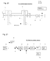
- Fig. 20 is a schematic conceptual diagram of a control object machine of this type.
- the machine 10 comprises a heavy article 11 , arm 12, sliding movement portion 13, slide rail portion 14, feed screw 15, coupling 16, motor 17, and any one of the machine control devices 20, 40, 43 to 48, and 50 to 54.
- the control object machine comprises the heavy article 11, arm 12, sliding movement portion 13, slide rail portion 14, feed screw 15, and coupling 16.
- the slide rail portion 14 constrains the sliding movement portion 13 to move only in the right-left movement directions in the figure. And, the contact portions of the slide rail portion 14 and the sliding movement portion 13 have low friction, so that the sliding movement portion 13 can move smoothly over the slide rail portion 14.
- the output shaft of the motor 17 is connected to the feed screw 15 via the coupling 16, and this feed screw 15 is screwed into a screw interior, not shown, mounted on the sliding movement portion 13. That is, through rotational driving of the feed screw 15 by the motor 17, the sliding movement portion 13 moves in the right and left directions in the figure according to position control operation by the machine control device.
- a long arm 12 is mounted on the sliding movement portion 13 which is positioned-controlled in this way, and a heavy article 11 is mounted on the end of this arm 12. Hence through position control of the sliding movement portion 13, the position of the heavy article 11 at the end of the arm 12 is also controlled.
- Fig. 21 shows the circuit configuration of a conventional machine control device 20 comprising functions to suppress the above-described vibration phenomenon; this circuit configuration is disclosed in Japanese Patent Application Laid-open No. 2003-76426 .
- This machine control device 20 comprises a position regulator 21, velocity regulator 22, torque regulator 23, position instruction block 24, correction block 25, and adder 26.
- a regulation operation is performed such that the position detection value from a motor encoder 17a mounted on the motor 17 matches the position instruction value of an instruction; the output is sent as a velocity instruction value to the velocity regulator 22.
- a regulation operation is performed such that the velocity detection value from the motor encoder 17a matches the velocity instruction value; the output is sent as a torque instruction value to the torque regulator 23.
- control is executed to drive the motor 17 according to the torque instruction value, via an inverter incorporated within the torque regulator 23, to move the sliding movement portion 13 of the machine 10 to a prescribed position, and to halt the machine.
- a position instruction value is output to move the sliding movement portion 13 to the target position; in the correction block 25, the second derivative value of the position instruction value (the acceleration instruction value) is multiplied by a prescribed gain to determine a correction amount, and this correction amount is added to the position instruction value by the adder 26; the addition value is sent to the position regulator 21 as the new position instruction value.
- a transfer function based on the above-described correction block 25 and adder 26 acts so as to cancel the vibration element component of the transfer function derived from the spring constant of the arm 12 and the mass of the heavy article 1 1 , so as to suppress the above-described vibration phenomenon in the control object machine.
- the proportional gain in order to quicken the response to a position instruction value, the proportional gain must be further increased in regulating operation of the position regulator 21 ; but when an abrupt disturbing torque occurs in the control object machine or at other times, if the proportional gain is made too great, there is the problem that vibration phenomena of the control object machine cannot be adequately suppressed.
- An object of this invention is to provide a machine control device for solving the above-mentioned problems.
- a machine control device according to claim 1 is proposed.
- the dependent claims relate to preferred embodiments of the present invention.
- a machine control device comprises correction means for determining a correction amount, based on an instruction value for any one of position, velocity and/or torque, from the nth derivative value (where n is a natural number equal to or greater than 2) of the instruction value; addition means for adding the correction amount to an instruction value for any one of position, velocity and/or torque; and control means for driving and controlling the control object machine according to output of the addition means.
- a correction amount is preferably determined for at least two of position, velocity and torque, and more preferably for any one of position, velocity and torque.
- the machine control device further comprises proportional gain setting means for setting a proportional gain, upon position regulation operation.
- the proportional gain setting means when a movement velocity based on the position instruction value decreases the proportional gain is preferably set high. Further when a movement velocity based on the position instruction value increases, the proportional gain is preferably set low.
- proportional gain setting means under conditions where abrupt disturbing torques occur to the control object machine, proportional gain is preferably set low. Further, under conditions where abrupt disturbing torques do not occur to the control object machine the proportional gain is preferably set high.
- the machine control device further comprises filter means for performing filter processing to the position instruction value, wherein the output value from this filter is taken as a new position instruction value, and constant setting means for setting a time constant of the filter and the correction gain of the correction means.
- the constant settings means, when the weight of a heavy article mounted on the control object machine is greater than a prescribed value and/or the length of an arm supporting the heavy article is greater than a prescribed value or the heavy article is at a high position, the time constant of the filter is preferably set high. Further, when the weight of the heavy article is smaller than the prescribed value and/or the length of the arm supporting the heavy article is smaller than a prescribed value or the heavy article is at a low position, the time constant of the filter is preferably set low.
- the correction gain of the correction means when the weight of a heavy article mounted on the control object is greater than a prescribed value and/or the length of an arm supporting the heavy object is greater than a prescribed value or the heavy article is at a high position, the correction gain of the correction means is preferably set high. Further, when the weight of the heavy article is smaller than the prescribed value and/or the length of the arm supporting the heavy article is smaller than a prescribed value or the heavy article is at a low position, the correction gain of the correction means is preferably set low when the weight of the heavy article is smaller than the prescribed value and/or the length of the arm supporting the heavy article is smaller than a prescribed value or the heavy article is at a low position, the correction gain of the correction means is preferably set low.
- a configuration is employed in which the proportional gain of position regulation operations in the machine control device can be varied, so that vibration phenomena of the control object machine can be advantageously suppressed, while still ensuring rapid response. Further, by employing a configuration in which the position instruction value is subjected to filter processing, and the time constant in this processing as well as the correction gain of the correction means can be varied, vibration phenomena of the control object machine can be effectively suppressed.
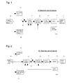
- Fig. 1 is a circuit configuration diagram of a machine control device, showing a first embodiment of the invention; portions which have the same functions as in the machine control device of the prior art shown in Fig. 21 are assigned the same symbols, and explanations thereof are omitted.
- the machine control device 40 shown in Fig. 1 differs from the conventional machine control device 20 in that, in place of a position regulator 21 with a fixed proportional gain during regulation operations, a position regulator 41 with a variable proportional gain during regulation operations is comprised; further, this machine control device 40 comprises proportional gain setting means 42, which issues an instruction to change the proportional gain of the position regulator 41 based on a position instruction value which is output from the position instruction block 24.
- this proportional gain setting means 42 when the movement velocity of the sliding movement portion 13 (see Fig. 20 ) based on the position instruction value from the position instruction block 24 is slow, that is, when the position instruction value results in a short movement distance, the proportional gain of the position regulator 41 is set high, and when the movement velocity based on the position instruction value is fast, that is, when the position instruction value results in a long movement distance, the proportional gain is set low.
- Fig. 2 is a circuit configuration diagram of a machine control device, showing a second embodiment of the invention; portions which have the same functions as in the machine control device shown in Fig. 1 are assigned the same symbols.
- the machine control device 43 shown in Fig. 2 differs from the machine control device 40 in that, in place of the correction block 25, a correction block 27 is comprised, and an adder 28 is further comprised; in addition, the adder 26 is omitted.
- the third derivative value of the position instruction value (a jerk instruction value) is multiplied by a prescribed gain to determine a correction amount, this correction amount is added to the velocity instruction value which is the output of the position regulator 41 by the adder 28, and the addition value is sent to the velocity regulator 22 as a new velocity instruction value.
- the transfer function based on the above-described correction block 27 and adder 28 acts so as to cancel the vibration element component of the transfer function derived from the spring constant of the arm 12 and the weight of the heavy article 11, so that the above-described vibration phenomena of the control object machine are suppressed.
- the proportional gain setting means 42 when the movement velocity of the sliding movement portion 13 (see Fig. 20 ) is slow based on the position instruction value from the position instruction block 24, that is, when the position instruction value is such that the movement distance is short, the proportional gain of the position regulator 41 is set high, and when the movement velocity based on the position instruction value is fast, that is, when the position instruction value is such that the movement distance is long, the proportional gain is set low.
- the position control performance can be improved while suppressing arm vibration phenomena arising from a high proportional gain.
- Fig. 3 is a circuit configuration diagram of a machine control device, showing a third embodiment of the invention; portions which have the same functions as in the machine control device shown in Fig. 1 are assigned the same symbols.
- the machine control device 44 shown in Fig. 3 is different from the machine control device 40 in that, in place of the correction block 25, a correction block 29 is comprised, and an adder 30 is comprised; in addition, the adder 26 is omitted.
- the fourth derivative value of the position instruction value is multiplied by a prescribed gain to determine a correction amount, and this correction amount is added to a torque instruction value which is the output of the velocity regulator 22 by the adder 30; this addition value is sent to the torque regulator 23 as a new torque instruction value.
- the transfer function based on the above-described correction block 29 and adder 30 acts so as to cancel the vibration element component of the transfer function derived from the spring constant of the arm 12 and the weight of the heavy article 11, so that the above-described vibration phenomena of the control object machine are suppressed.
- the proportional gain setting means 42 when the movement velocity of the sliding movement portion 13 (see Fig. 20 ) based on the position instruction value from the position instruction block 24 is slow, that is, when the position instruction value is such that the movement distance is short, the proportional gain of the position regulator 41 is set high, and when the movement velocity based on the position instruction value is fast, that is, when the position instruction value is such that the movement distance is long, the proportional gain is set low.
- the position control performance can be improved while suppressing arm vibration phenomena arising from a high proportional gain.
- Fig. 4 is a circuit configuration diagram of a machine control device, showing a fourth embodiment of the invention; portions which have the same functions as in the machine control device shown in Fig. 1 are assigned the same symbols.
- the machine control device 45 shown in Fig. 4 is different from the machine control device 40 in that, in place of the correction block 25, a correction block 31 is comprised, and in addition an adder 32 is comprised, and the adder 26 is omitted.
- the second derivative value of the velocity instruction value (an acceleration instruction value) which is the output of the position regulator 41 is multiplied by a prescribed gain to determine a correction amount, and this correction amount is added to the velocity instruction value by the adder 32; this addition value is sent to the velocity regulator 22 as a new velocity instruction value.
- the transfer function based on the above-described correction block 31 and adder 32 acts so as to cancel the vibration element component of the transfer function derived from the spring constant of the arm 12 and the weight of the heavy article 11, so that the above-described vibration phenomena of the control object machine are suppressed.
- the proportional gain setting means 42 when the movement velocity of the sliding movement portion 13 (see Fig. 20 ) based on the position instruction value from the position instruction block 24 is slow, that is, when the position instruction value is such that the movement distance is short, the proportional gain of the position regulator 41 is set high, and when the movement velocity based on the position instruction value is fast, that is, when the position instruction value is such that the movement distance is long, the proportional gain is set low.
- the position control performance can be improved while suppressing arm vibration phenomena arising from a high proportional gain.
- Fig. 5 is a circuit configuration diagram of a machine control device, showing a fifth embodiment of the invention; portions which have the same functions as in the machine control device shown in Fig. 1 are assigned the same symbols.
- the machine control device 46 shown in Fig. 5 is different from the machine control device 40 in that, in place of the correction block 25, a correction block 33 is comprised, and in addition an adder 34 is comprised, and the adder 26 is omitted.
- the third derivative value of the velocity instruction value which is the output of the position regulator 41 is multiplied by a prescribed gain to determine a correction amount, this correction amount is added to a torque instruction value which is the output of the velocity regulator 41 by the adder 34, and this addition value is sent to the torque regulator 23 as a new torque instruction value.
- the transfer function based on the above-described correction block 33 and adder 34 acts so as to cancel the vibration element component of the transfer function derived from the spring constant of the arm 12 and the weight of the heavy article 11, so that the above-described vibration phenomena of the control object machine are suppressed.
- the proportional gain setting means 42 when the movement velocity of the sliding movement portion 13 (see Fig. 20 ) based on the position instruction value from the position instruction block 24 is slow, that is, when the position instruction value is such that the movement distance is short, the proportional gain of the position regulator 41 is set high, and when the movement velocity based on the position instruction value is fast, that is, when the position instruction value is such that the movement distance is long, the proportional gain is set low.
- the position control performance can be improved while suppressing arm vibration phenomena arising from a high proportional gain.
- Fig. 6 is a circuit configuration diagram of a machine control device, showing a sixth embodiment of the invention; portions which have the same functions as in the machine control device shown in Fig. 1 are assigned the same symbols.
- the machine control device 47 shown in Fig. 6 is different from the machine control device 40 in that, in place of the correction block 25, a correction block 35 is comprised, and in addition an adder 34 is comprised, and the adder 26 is omitted.
- the second derivative value of the torque instruction value which is the output of the velocity regulator 22 is multiplied by a prescribed gain to determine a correction amount, this correction amount is added to the torque instruction value by the adder 34, and this addition value is sent to the torque regulator 23 as a new torque instruction value.
- the transfer function based on the above-described correction block 35 and adder 34 acts so as to cancel the vibration element component of the transfer function derived from the spring constant of the arm 12 and the weight of the heavy article 11, so that the above-described vibration phenomena of the control object machine are suppressed.
- the proportional gain setting means 42 when the movement velocity of the sliding movement portion 13 (see Fig. 20 ) based on the position instruction value from the position instruction block 24 is slow, that is, when the position instruction value is such that the movement distance is short, the proportional gain of the position regulator 41 is set high, and when the movement velocity based on the position instruction value is fast, that is, when the position instruction value is such that the movement distance is long, the proportional gain is set low.
- the position control performance can be improved while suppressing arm vibration phenomena arising from a high proportional gain.
- Fig. 7 is a circuit configuration diagram of a machine control device, showing a seventh embodiment of the invention; portions which have the same functions as in the machine control device shown in Fig. 1 are assigned the same symbols.
- the machine control device 48 shown in Fig. 7 is different from the machine control device 40 in that, in place of the proportional gain setting means 42, a proportional gain setting means 49 is comprised.
- the proportional gain setting means 49 when conditions are such that abrupt disturbing torques occur in the control object machine, the proportional gain of the position regulator 41 is set low, and when conditions are such that abrupt disturbing torques do not occur in the control object machine, the proportional gain is set high.
- the position control performance can be improved while suppressing arm vibration phenomena arising from abrupt disturbing torques in the control object machine.
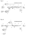
- Fig. 8 is a circuit configuration diagram of a machine control device, showing an eighth embodiment of the invention; portions which have the same functions as in the machine control device shown in Fig. 2 are assigned the same symbols.
- the machine control device 50 shown in Fig. 8 is different from the machine control device 43 in that, in place of the proportional gain setting means 42, a proportional gain setting means 49 is comprised.
- the proportional gain setting means 49 when conditions are such that abrupt disturbing torques occur in the control object machine, the proportional gain of the position regulator 41 is set low, and when conditions are such that abrupt disturbing torques do not occur in the control object machine, the proportional gain is set high.
- the position control performance can be improved while suppressing arm vibration phenomena arising from abrupt disturbing torques in the control object machine.
- Fig. 9 is a circuit configuration diagram of a machine control device, showing a ninth embodiment of the invention; portions which have the same functions as in the machine control device shown in Fig. 3 are assigned the same symbols.
- the machine control device 51 shown in Fig. 9 is different from the machine control device 44 in that, in place of the proportional gain setting means 42, a proportional gain setting means 49 is comprised.
- the proportional gain setting means 49 when conditions are such that abrupt disturbing torques occur in the control object machine, the proportional gain of the position regulator 41 is set low, and when conditions are such that abrupt disturbing torques do not occur in the control object machine, the proportional gain is set high.
- the position control performance can be improved while suppressing arm vibration phenomena arising from abrupt disturbing torques in the control object machine.
- Fig. 10 is a circuit configuration diagram of a machine control device, showing a tenth embodiment of the invention; portions which have the same functions as in the machine control device shown in Fig. 4 are assigned the same symbols.
- the machine control device 52 shown in Fig. 10 is different from the machine control device 45 in that, in place of the proportional gain setting means 42, a proportional gain setting means 49 is comprised.
- the proportional gain setting means 49 when conditions are such that abrupt disturbing torques occur in the control object machine, the proportional gain of the position regulator 41 is set low, and when conditions are such that abrupt disturbing torques do not occur in the control object machine, the proportional gain is set high.
- the position control performance can be improved while suppressing arm vibration phenomena arising from abrupt disturbing torques in the control object machine.
- Fig. 11 is a circuit configuration diagram of a machine control device, showing an eleventh embodiment of the invention; portions which have the same functions as in the machine control device shown in Fig. 5 are assigned the same symbols.
- the machine control device 53 shown in Fig. 11 is different from the machine control device 46 in that, in place of the proportional gain setting means 42, a proportional gain setting means 49 is comprised.
- the proportional gain setting means 49 when conditions are such that abrupt disturbing torques occur in the control object machine, the proportional gain of the position regulator 41 is set low, and when conditions are such that abrupt disturbing torques do not occur in the control object machine, the proportional gain is set high.
- the position control performance can be improved while suppressing arm vibration phenomena arising from abrupt disturbing torques in the control object machine.
- Fig. 12 is a circuit configuration diagram of a machine control device, showing a twelfth embodiment of the invention; portions which have the same functions as in the machine control device shown in Fig. 6 are assigned the same symbols.
- the machine control device 54 shown in Fig. 12 is different from the machine control device 47 in that, in place of the proportional gain setting means 42, a proportional gain setting means 49 is comprised.
- the proportional gain setting means 49 when conditions are such that abrupt disturbing torques occur in the control object machine, the proportional gain of the position regulator 41 is set low, and when conditions are such that abrupt disturbing torques do not occur in the control object machine, the proportional gain is set high.
- the position control performance can be improved while suppressing arm vibration phenomena arising from abrupt disturbing torques in the control object machine.
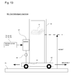
- Fig. 13 is a schematic conceptual diagram of a control object machine different from that of the above Fig. 20 .
- This machine 60 comprises a heavy article 61, gate-shaped arm 62, dolly 63, wheels 64, rail 65, coupling 66, motor 67, and any one of the machine control devices 70, 74, 76, 78, 80, and 82.
- the control object machine comprises the heavy article 61, gate-shaped arm 62, dolly 63, wheels 64, rail 65, and coupling 66.
- This control object machine is used in equipment to transport goods in a multilevel warehouse and in other applications.
- the dolly 63 is designed to be able to move smoothly on the rail 65 via the wheels 64 in the left-right directions of motion in the figure.
- the output shaft of the motor 67 is connected via the coupling 66 to wheels 64. That is, the dolly 63 moves in the left and right directions in the figure through rotational driving of wheels 64 by the motor 67 via the coupling 66, according to position control operation of the machine control device.
- the gate-shaped arm 62 is mounted on the dolly 63 the position of which is controlled in this manner; on this gate-shaped arm 62 is mounted a heavy article 61, of which the height position from the rail 65, shown in the figure, can be varied. Hence by means of position control of the dolly 63, the position of the heavy article 61 supported by the gate-shaped arm 62 can also be controlled.
- the motor 17 and machine 10 in the machine control devices shown in Fig. 1 to Fig. 12 can be taken to be the motor 67 and machine 60 in the configuration shown in Fig. 13 .
- information on the positions of joints in the rail 65 may be set in advance, and based on position information from the motor encoder 17a, the proportional gain of the position regulator 41 may be set low when the dolly 63 passes over joints in the rail 65.
- Fig. 14 is a circuit configuration diagram of a machine control device, showing a thirteenth embodiment of the invention comprising the above-described function to suppress vibration phenomena; portions which have the same functions as in the machine control device shown in Fig. 21 are assigned the same symbols.
- the machine control device 70 shown in Fig. 14 is different from the machine control device 20 of the prior art in that a filter 71 is added which performs filter processing of position instruction values output by the position instruction block 24, and in place of a correction block 25 with a fixed correction gain which takes values output from this filter 71 as new position instruction values, a correction block 72 is comprised which enables variation of the correction gain, while employing a correction amount derivation method similar to that of the correction block 25; in addition, constant setting means 73, which issues instructions for the filter time constant in the filter 71 and for the correction gain in the correction block 72, is comprised.
- this constant setting means 73 when the weight of the heavy article 61 mounted on the control object machine is greater than a prescribed value, and moreover the heavy article 61 is at a high position, the time constant of the filter 71 is set high and the correction gain of the correction block 72 is set high; and when the weight of the heavy article 61 is smaller than the prescribed value or the heavy article 61 is at a low position, the time constant of the filter 71 is set low and the correction gain of the correction block 72 is set low.
- the correction gain of the correction block 72 is proportional to the reciprocal of the square of the vibration frequency, when the arm is long or when the heavy article is at a high position, the vibration frequency is low, and so the correction gain of the correction block 72 is high.
- the filter 71 performs filter processing of a position instruction value output from the position instruction block 24, and by taking this as a new position instruction value, measures are taken to gradually increase or decrease the new position instruction value under conditions in which the above-described vibration phenomena occur, and in addition the correction gain of the correction block 72 is set high, and vibration phenomena are suppressed.
- Fig. 15 is a circuit configuration diagram of a machine control device, showing a fourteenth embodiment of the invention; portions which have the same functions as in the machine control device shown in Fig. 14 are assigned the same symbols.
- the machine control device 74 shown in Fig. 15 is different from the machine control device 70 in that, in place of the correction block 72, a correction block 75 is comprised which enables variation of the correction gain, while employing a correction amount derivation method similar to that of the correction block 27; in addition, an adder 28 is comprised, and the adder 26 is omitted.
- the time constant of the filter 71 when the weight of the heavy article 61 mounted on the control object machine is greater than a prescribed value, and moreover the heavy article 61 is at a high position, the time constant of the filter 71 is set high and the correction gain of the correction block 75 is set high; and when the weight of the heavy article 61 is smaller than the prescribed value or the heavy article 61 is at a low position, the time constant of the filter 71 is set low and the correction gain of the correction block 75 is set low.
- the filter 71 performs filter processing of a position instruction value output from the position instruction block 24, and by taking this as a new position instruction value, measures are taken to gradually increase or decrease the new position instruction value under conditions in which the above-described vibration phenomena occur, and in addition the correction gain of the correction block 75 is set high, and vibration phenomena are suppressed.
- Fig. 16 is a circuit configuration diagram of a machine control device, showing a fifteenth embodiment of the invention comprising the above-described function to suppress vibration phenomena; portions which have the same functions as in the machine control device shown in Fig. 14 are assigned the same symbols.
- the machine control device 76 shown in Fig. 16 is different from the machine control device 70 in that, in place of the correction block 72, a correction block 77 is comprised which enables variation of the correction gain, while employing a correction amount derivation method similar to that of the correction block 29; in addition, an adder 30 is comprised, and the adder 26 is omitted.
- the time constant of the filter 71 when the weight of the heavy article 61 mounted on the control object machine is greater than a prescribed value, and moreover the heavy article 61 is at a high position, the time constant of the filter 71 is set high and the correction gain of the correction block 77 is set high; and when the weight of the heavy article 61 is smaller than the prescribed value or the heavy article 61 is at a low position, the time constant of the filter 71 is set low and the correction gain of the correction block 77 is set low.
- the filter 71 performs filter processing of a position instruction value output from the position instruction block 24, and by taking this as a new position instruction value, measures are taken to gradually increase or decrease the new position instruction value under conditions in which the above-described vibration phenomena occur, and in addition the correction gain of the correction block 77 is set high, and vibration phenomena are suppressed.
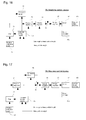
- Fig. 17 is a circuit configuration diagram of a machine control device, showing a sixteenth embodiment of the invention; portions which have the same functions as in the machine control device shown in Fig. 14 are assigned the same symbols.
- the machine control device 78 shown in Fig. 17 is different from the machine control device 70 in that, in place of the correction block 72, a correction block 79 is comprised which enables variation of the correction gain, while employing a correction amount derivation method similar to that of the correction block 31 ; in addition, an adder 32 is comprised, and the adder 26 is omitted.
- the time constant of the filter 71 when the weight of the heavy article 61 mounted on the control object machine is greater than a prescribed value, and moreover the heavy article 61 is at a high position, the time constant of the filter 71 is set high and the correction gain of the correction block 79 is set high; and when the weight of the heavy article 61 is smaller than the prescribed value or the heavy article 61 is at a low position, the time constant of the filter 71 is set low and the correction gain of the correction block 79 is set low.
- the filter 71 performs filter processing of a position instruction value output from the position instruction block 24, and by taking this as a new position instruction value, measures are taken to gradually increase or decrease the new position instruction value under conditions in which the above-described vibration phenomena occur, and in addition the correction gain of the correction block 79 is set high, and vibration phenomena are suppressed.
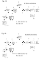
- Fig. 18 is a circuit configuration diagram of a machine control device, showing a seventeenth embodiment of the invention; portions which have the same functions as in the machine control device shown in Fig. 14 are assigned the same symbols.
- the machine control device 80 shown in Fig. 18 is different from the machine control device 70 in that, in place of the correction block 72, a correction block 81 is comprised which enables variation of the correction gain, while employing a correction amount derivation method similar to that of the correction block 33; in addition, an adder 34 is comprised, and the adder 26 is omitted.
- the time constant of the filter 71 when the weight of the heavy article 61 mounted on the control object machine is greater than a prescribed value, and moreover the heavy article 61 is at a high position, the time constant of the filter 71 is set high and the correction gain of the correction block 81 is set high; and when the weight of the heavy article 61 is smaller than the prescribed value or the heavy article 61 is at a low position, the time constant of the filter 71 is set low and the correction gain of the correction block 81 is set low.
- the filter 71 performs filter processing of a position instruction value output from the position instruction block 24, and by taking this as a new position instruction value, measures are taken to gradually increase or decrease the new position instruction value under conditions in which the above-described vibration phenomena occur, and in addition the correction gain of the correction block 81 is set high, and vibration phenomena are suppressed.
- Fig. 19 is a circuit configuration diagram of a machine control device, showing an eighteenth embodiment of the invention; portions which have the same functions as in the machine control device shown in Fig. 14 are assigned the same symbols.
- the machine control device 82 shown in Fig. 19 is different from the machine control device 70 in that, in place of the correction block 72, a correction block 83 is comprised which enables variation of the correction gain, while employing a correction amount derivation method similar to that of the correction block 35; in addition, an adder 34 is comprised, and the adder 26 is omitted.
- the time constant of the filter 71 when the weight of the heavy article 61 mounted on the control object machine is greater than a prescribed value, and moreover the heavy article 61 is at a high position, the time constant of the filter 71 is set high and the correction gain of the correction block 83 is set high; and when the weight of the heavy article 61 is smaller than the prescribed value or the heavy article 61 is at a low position, the time constant of the filter 71 is set low and the correction gain of the correction block 83 is set low.
- the filter 71 performs filter processing of a position instruction value output from the position instruction block 24, and by taking this as a new position instruction value, measures are taken to gradually increase or decrease the new position instruction value under conditions in which the above-described vibration phenomena occur, and in addition the correction gain of the correction block 83 is set high, and vibration phenomena are suppressed.
- the constant setting means 73 when the weight of the heavy article 11 mounted on the control object machine is greater than a prescribed value, and moreover the arm 12 is long, the time constant of the filter 71 is set high and the correction gain of the correction block is set high; and when the arm 12 is short, the time constant of the filter 71 is set low and the correction gain of the correction block is set low.
Landscapes
- Engineering & Computer Science (AREA)
- Physics & Mathematics (AREA)
- General Physics & Mathematics (AREA)
- Automation & Control Theory (AREA)
- Mechanical Engineering (AREA)
- Human Computer Interaction (AREA)
- Manufacturing & Machinery (AREA)
- Feedback Control In General (AREA)
- Control Of Position Or Direction (AREA)
- Operation Control Of Excavators (AREA)
Abstract
Description
- The present invention relates to a machine control device for moving a control object machine to a target position and halting the machine, and to a machine control device which is capable of suppressing vibration of the control object machine due to inertial forces at the time of halting.
-
Fig. 20 is a schematic conceptual diagram of a control object machine of this type. - The
machine 10 comprises aheavy article 11 ,arm 12,sliding movement portion 13,slide rail portion 14,feed screw 15,coupling 16,motor 17, and any one of themachine control devices heavy article 11,arm 12,sliding movement portion 13,slide rail portion 14,feed screw 15, andcoupling 16. - In
Fig. 20 , theslide rail portion 14 constrains thesliding movement portion 13 to move only in the right-left movement directions in the figure. And, the contact portions of theslide rail portion 14 and thesliding movement portion 13 have low friction, so that thesliding movement portion 13 can move smoothly over theslide rail portion 14. The output shaft of themotor 17 is connected to thefeed screw 15 via thecoupling 16, and thisfeed screw 15 is screwed into a screw interior, not shown, mounted on thesliding movement portion 13. That is, through rotational driving of thefeed screw 15 by themotor 17, thesliding movement portion 13 moves in the right and left directions in the figure according to position control operation by the machine control device. - A
long arm 12 is mounted on thesliding movement portion 13 which is positioned-controlled in this way, and aheavy article 11 is mounted on the end of thisarm 12. Hence through position control of thesliding movement portion 13, the position of theheavy article 11 at the end of thearm 12 is also controlled. - For the configuration shown in
Fig. 20 , it is known that even when thesliding movement portion 13 is halted at the target position, theheavy article 11 at the end of thearm 12 causes thearm 12 to flex due to its own inertial force, advancing further than the instructed position, so that halting may not be immediate and vibration may occur even after thesliding movement portion 13 has halted at the target position. -
Fig. 21 shows the circuit configuration of a conventionalmachine control device 20 comprising functions to suppress the above-described vibration phenomenon; this circuit configuration is disclosed in Japanese Patent Application Laid-open No.2003-76426 - This
machine control device 20 comprises aposition regulator 21,velocity regulator 22,torque regulator 23,position instruction block 24,correction block 25, andadder 26. - In
Fig. 21 , in theposition regulator 21, a regulation operation is performed such that the position detection value from amotor encoder 17a mounted on themotor 17 matches the position instruction value of an instruction; the output is sent as a velocity instruction value to thevelocity regulator 22. In thevelocity regulator 22, a regulation operation is performed such that the velocity detection value from themotor encoder 17a matches the velocity instruction value; the output is sent as a torque instruction value to thetorque regulator 23. - In the
torque regulator 23, control is executed to drive themotor 17 according to the torque instruction value, via an inverter incorporated within thetorque regulator 23, to move thesliding movement portion 13 of themachine 10 to a prescribed position, and to halt the machine. - In the
position instruction block 24, a position instruction value is output to move thesliding movement portion 13 to the target position; in thecorrection block 25, the second derivative value of the position instruction value (the acceleration instruction value) is multiplied by a prescribed gain to determine a correction amount, and this correction amount is added to the position instruction value by theadder 26; the addition value is sent to theposition regulator 21 as the new position instruction value. - That is, in the
machine control device 20 shown inFig. 21 , a transfer function based on the above-describedcorrection block 25 andadder 26 acts so as to cancel the vibration element component of the transfer function derived from the spring constant of thearm 12 and the mass of the heavy article 1 1 , so as to suppress the above-described vibration phenomenon in the control object machine. - In the conventional
machine control device 20 shown inFig. 21 , in order to quicken the response to a position instruction value, the proportional gain must be further increased in regulating operation of theposition regulator 21 ; but when an abrupt disturbing torque occurs in the control object machine or at other times, if the proportional gain is made too great, there is the problem that vibration phenomena of the control object machine cannot be adequately suppressed. - Further, when the arm of the control object machine is long and the rigidity thereof is low, or when the heavy article is heavy and the position thereof is high, there has been the problem that in the circuit configuration of the conventional
machine control device 20, vibration phenomena of the control object machine cannot adequately be suppressed. - An object of this invention is to provide a machine control device for solving the above-mentioned problems. For solving the object of the present invention, a machine control device according to claim 1 is proposed. The dependent claims relate to preferred embodiments of the present invention.
- According to the present invention, a machine control device, comprises correction means for determining a correction amount, based on an instruction value for any one of position, velocity and/or torque, from the nth derivative value (where n is a natural number equal to or greater than 2) of the instruction value; addition means for adding the correction amount to an instruction value for any one of position, velocity and/or torque; and control means for driving and controlling the control object machine according to output of the addition means. Here, a correction amount is preferably determined for at least two of position, velocity and torque, and more preferably for any one of position, velocity and torque. Preferably, the machine control device further comprises proportional gain setting means for setting a proportional gain, upon position regulation operation.
- According to an aspect of the present invention, in the proportional gain setting means, when a movement velocity based on the position instruction value decreases the proportional gain is preferably set high. Further when a movement velocity based on the position instruction value increases, the proportional gain is preferably set low.
- According to an aspect of the present invention, in the proportional gain setting means, under conditions where abrupt disturbing torques occur to the control object machine, proportional gain is preferably set low. Further, under conditions where abrupt disturbing torques do not occur to the control object machine the proportional gain is preferably set high.
- According to an aspect of the present invention, the machine control device further comprises filter means for performing filter processing to the position instruction value, wherein the output value from this filter is taken as a new position instruction value, and constant setting means for setting a time constant of the filter and the correction gain of the correction means.
- According to an aspect of the present invention, in the constant settings means, when the weight of a heavy article mounted on the control object machine is greater than a prescribed value and/or the length of an arm supporting the heavy article is greater than a prescribed value or the heavy article is at a high position, the time constant of the filter is preferably set high. Further, when the weight of the heavy article is smaller than the prescribed value and/or the length of the arm supporting the heavy article is smaller than a prescribed value or the heavy article is at a low position, the time constant of the filter is preferably set low.
- According to an aspect of the present invention, in the constant settings means, when the weight of a heavy article mounted on the control object is greater than a prescribed value and/or the length of an arm supporting the heavy object is greater than a prescribed value or the heavy article is at a high position, the correction gain of the correction means is preferably set high. Further, when the weight of the heavy article is smaller than the prescribed value and/or the length of the arm supporting the heavy article is smaller than a prescribed value or the heavy article is at a low position, the correction gain of the correction means is preferably set low.
- By means of this invention, a configuration is employed in which the proportional gain of position regulation operations in the machine control device can be varied, so that vibration phenomena of the control object machine can be advantageously suppressed, while still ensuring rapid response. Further, by employing a configuration in which the position instruction value is subjected to filter processing, and the time constant in this processing as well as the correction gain of the correction means can be varied, vibration phenomena of the control object machine can be effectively suppressed.
-
- Fig. 1
- shows a circuit configuration diagram of a machine control device according to a first embodiment of the invention;
- Fig. 2
- shows a circuit configuration diagram of a machine control device, according to a second embodiment of the invention;
- Fig. 3
- shows a circuit configuration diagram of a machine control device according to a third embodiment of the invention;
- Fig. 4
- shows a circuit configuration diagram of a machine control device according to a fourth embodiment of the invention;
- Fig. 5
- shows a circuit configuration diagram of a machine control device according to a fifth embodiment of the invention;
- Fig. 6
- shows a circuit configuration diagram of a machine control device according to a sixth embodiment of the invention;
- Fig. 7
- shows a circuit configuration diagram of a machine control device according to a seventh embodiment of the invention;
- Fig. 8
- shows a circuit configuration diagram of a machine control device according to an eighth embodiment of the invention;
- Fig. 9
- shows a circuit configuration diagram of a machine control device according to a ninth embodiment of the invention;
- Fig. 10
- shows a circuit configuration diagram of a machine control device according to a tenth embodiment of the invention;
- Fig. 11
- shows a circuit configuration diagram of a machine control device according to an eleventh embodiment of the invention;
- Fig. 12
- shows a circuit configuration diagram of a machine control device according to a twelfth embodiment of the invention;
- Fig. 13
- shows a schematic conceptual diagram of a control object machine;
- Fig. 14
- shows a circuit configuration diagram of a machine control device according to a thirteenth embodiment of the invention;
- Fig. 15
- shows a circuit configuration diagram of a machine control device according to a fourteenth embodiment of the invention;
- Fig. 16
- shows a circuit configuration diagram of a machine control device according to a fifteenth embodiment of the invention;
- Fig. 17
- shows a circuit configuration diagram of a machine control device according to a sixteenth embodiment of the invention;
- Fig. 18
- shows a circuit configuration diagram of a machine control device according to a seventeenth embodiment of the invention;
- Fig. 19
- shows a circuit configuration diagram of a machine control device according to an eighteenth embodiment of the invention;
- Fig. 20
- shows a schematic conceptual diagram of a control object machine; and,
- Fig. 21
- shows a circuit configuration diagram of a machine control device according to an example of the prior art.
-
Fig. 1 is a circuit configuration diagram of a machine control device, showing a first embodiment of the invention; portions which have the same functions as in the machine control device of the prior art shown inFig. 21 are assigned the same symbols, and explanations thereof are omitted. - That is, the
machine control device 40 shown inFig. 1 differs from the conventionalmachine control device 20 in that, in place of aposition regulator 21 with a fixed proportional gain during regulation operations, aposition regulator 41 with a variable proportional gain during regulation operations is comprised; further, thismachine control device 40 comprises proportional gain setting means 42, which issues an instruction to change the proportional gain of theposition regulator 41 based on a position instruction value which is output from theposition instruction block 24. - In this proportional gain setting means 42, when the movement velocity of the sliding movement portion 13 (see
Fig. 20 ) based on the position instruction value from theposition instruction block 24 is slow, that is, when the position instruction value results in a short movement distance, the proportional gain of theposition regulator 41 is set high, and when the movement velocity based on the position instruction value is fast, that is, when the position instruction value results in a long movement distance, the proportional gain is set low. - As a result, in a control object machine using this
machine control device 40, the performance of position control can be improved while suppressing arm vibration phenomena arising from a high proportional gain. -
Fig. 2 is a circuit configuration diagram of a machine control device, showing a second embodiment of the invention; portions which have the same functions as in the machine control device shown inFig. 1 are assigned the same symbols. - That is, the
machine control device 43 shown inFig. 2 differs from themachine control device 40 in that, in place of thecorrection block 25, acorrection block 27 is comprised, and anadder 28 is further comprised; in addition, theadder 26 is omitted. - In this
correction block 27, the third derivative value of the position instruction value (a jerk instruction value) is multiplied by a prescribed gain to determine a correction amount, this correction amount is added to the velocity instruction value which is the output of theposition regulator 41 by theadder 28, and the addition value is sent to thevelocity regulator 22 as a new velocity instruction value. - That is, in the
machine control device 43 shown inFig. 2 , the transfer function based on the above-describedcorrection block 27 andadder 28 acts so as to cancel the vibration element component of the transfer function derived from the spring constant of thearm 12 and the weight of theheavy article 11, so that the above-described vibration phenomena of the control object machine are suppressed. - Further, in the proportional gain setting means 42, when the movement velocity of the sliding movement portion 13 (see
Fig. 20 ) is slow based on the position instruction value from theposition instruction block 24, that is, when the position instruction value is such that the movement distance is short, the proportional gain of theposition regulator 41 is set high, and when the movement velocity based on the position instruction value is fast, that is, when the position instruction value is such that the movement distance is long, the proportional gain is set low. - As a result, in the control object machine using this
machine control device 43, the position control performance can be improved while suppressing arm vibration phenomena arising from a high proportional gain. -
Fig. 3 is a circuit configuration diagram of a machine control device, showing a third embodiment of the invention; portions which have the same functions as in the machine control device shown inFig. 1 are assigned the same symbols. - That is, the
machine control device 44 shown inFig. 3 is different from themachine control device 40 in that, in place of thecorrection block 25, acorrection block 29 is comprised, and anadder 30 is comprised; in addition, theadder 26 is omitted. - In this
correction block 29, the fourth derivative value of the position instruction value is multiplied by a prescribed gain to determine a correction amount, and this correction amount is added to a torque instruction value which is the output of thevelocity regulator 22 by theadder 30; this addition value is sent to thetorque regulator 23 as a new torque instruction value. - That is, in the
machine control device 44 shown inFig. 3 , the transfer function based on the above-describedcorrection block 29 andadder 30 acts so as to cancel the vibration element component of the transfer function derived from the spring constant of thearm 12 and the weight of theheavy article 11, so that the above-described vibration phenomena of the control object machine are suppressed. - Further, in the proportional gain setting means 42, when the movement velocity of the sliding movement portion 13 (see
Fig. 20 ) based on the position instruction value from theposition instruction block 24 is slow, that is, when the position instruction value is such that the movement distance is short, the proportional gain of theposition regulator 41 is set high, and when the movement velocity based on the position instruction value is fast, that is, when the position instruction value is such that the movement distance is long, the proportional gain is set low. - As a result, in the control object machine using this
machine control device 44, the position control performance can be improved while suppressing arm vibration phenomena arising from a high proportional gain. -
Fig. 4 is a circuit configuration diagram of a machine control device, showing a fourth embodiment of the invention; portions which have the same functions as in the machine control device shown inFig. 1 are assigned the same symbols. - That is, the
machine control device 45 shown inFig. 4 is different from themachine control device 40 in that, in place of thecorrection block 25, acorrection block 31 is comprised, and in addition anadder 32 is comprised, and theadder 26 is omitted. - In this
correction block 31, the second derivative value of the velocity instruction value (an acceleration instruction value) which is the output of theposition regulator 41 is multiplied by a prescribed gain to determine a correction amount, and this correction amount is added to the velocity instruction value by theadder 32; this addition value is sent to thevelocity regulator 22 as a new velocity instruction value. - That is, in the
machine control device 45 shown inFig. 2 , the transfer function based on the above-describedcorrection block 31 andadder 32 acts so as to cancel the vibration element component of the transfer function derived from the spring constant of thearm 12 and the weight of theheavy article 11, so that the above-described vibration phenomena of the control object machine are suppressed. - Further, in the proportional gain setting means 42, when the movement velocity of the sliding movement portion 13 (see
Fig. 20 ) based on the position instruction value from theposition instruction block 24 is slow, that is, when the position instruction value is such that the movement distance is short, the proportional gain of theposition regulator 41 is set high, and when the movement velocity based on the position instruction value is fast, that is, when the position instruction value is such that the movement distance is long, the proportional gain is set low. - As a result, in the control object machine using this
machine control device 45, the position control performance can be improved while suppressing arm vibration phenomena arising from a high proportional gain. -
Fig. 5 is a circuit configuration diagram of a machine control device, showing a fifth embodiment of the invention; portions which have the same functions as in the machine control device shown inFig. 1 are assigned the same symbols. - That is, the machine control device 46 shown in
Fig. 5 is different from themachine control device 40 in that, in place of thecorrection block 25, a correction block 33 is comprised, and in addition anadder 34 is comprised, and theadder 26 is omitted. - In the correction block 33, the third derivative value of the velocity instruction value which is the output of the
position regulator 41 is multiplied by a prescribed gain to determine a correction amount, this correction amount is added to a torque instruction value which is the output of thevelocity regulator 41 by theadder 34, and this addition value is sent to thetorque regulator 23 as a new torque instruction value. - That is, in the machine control device 46 shown in
Fig. 5 , the transfer function based on the above-described correction block 33 andadder 34 acts so as to cancel the vibration element component of the transfer function derived from the spring constant of thearm 12 and the weight of theheavy article 11, so that the above-described vibration phenomena of the control object machine are suppressed. - Further, in the proportional gain setting means 42, when the movement velocity of the sliding movement portion 13 (see
Fig. 20 ) based on the position instruction value from theposition instruction block 24 is slow, that is, when the position instruction value is such that the movement distance is short, the proportional gain of theposition regulator 41 is set high, and when the movement velocity based on the position instruction value is fast, that is, when the position instruction value is such that the movement distance is long, the proportional gain is set low. - As a result, in the control object machine using this machine control device 46, the position control performance can be improved while suppressing arm vibration phenomena arising from a high proportional gain.
-
Fig. 6 is a circuit configuration diagram of a machine control device, showing a sixth embodiment of the invention; portions which have the same functions as in the machine control device shown inFig. 1 are assigned the same symbols. - That is, the
machine control device 47 shown inFig. 6 is different from themachine control device 40 in that, in place of thecorrection block 25, acorrection block 35 is comprised, and in addition anadder 34 is comprised, and theadder 26 is omitted. - In the
correction block 35, the second derivative value of the torque instruction value which is the output of thevelocity regulator 22 is multiplied by a prescribed gain to determine a correction amount, this correction amount is added to the torque instruction value by theadder 34, and this addition value is sent to thetorque regulator 23 as a new torque instruction value. - That is, in the
machine control device 47 shown inFig. 6 , the transfer function based on the above-describedcorrection block 35 andadder 34 acts so as to cancel the vibration element component of the transfer function derived from the spring constant of thearm 12 and the weight of theheavy article 11, so that the above-described vibration phenomena of the control object machine are suppressed. - Further, in the proportional gain setting means 42, when the movement velocity of the sliding movement portion 13 (see
Fig. 20 ) based on the position instruction value from theposition instruction block 24 is slow, that is, when the position instruction value is such that the movement distance is short, the proportional gain of theposition regulator 41 is set high, and when the movement velocity based on the position instruction value is fast, that is, when the position instruction value is such that the movement distance is long, the proportional gain is set low. - As a result, in the control object machine using this
machine control device 47, the position control performance can be improved while suppressing arm vibration phenomena arising from a high proportional gain. -
Fig. 7 is a circuit configuration diagram of a machine control device, showing a seventh embodiment of the invention; portions which have the same functions as in the machine control device shown inFig. 1 are assigned the same symbols. - That is, the
machine control device 48 shown inFig. 7 is different from themachine control device 40 in that, in place of the proportional gain setting means 42, a proportional gain setting means 49 is comprised. - In the proportional gain setting means 49, when conditions are such that abrupt disturbing torques occur in the control object machine, the proportional gain of the
position regulator 41 is set low, and when conditions are such that abrupt disturbing torques do not occur in the control object machine, the proportional gain is set high. - For example, in cases in which abrupt disturbing torques occur in the control object machine, "1" is input to the proportional gain setting means 49 from outside as the machine conditions, and the proportional gain of the
position regulator 41 is set low; conversely, in cases in which abrupt disturbing torques do not occur in the control object machine, "0" is input to the proportional gain setting means 49 from outside as the machine conditions, and the proportional gain of theposition regulator 41 is set high. - As a result, in the control object machine using this
machine control device 48, the position control performance can be improved while suppressing arm vibration phenomena arising from abrupt disturbing torques in the control object machine. -
Fig. 8 is a circuit configuration diagram of a machine control device, showing an eighth embodiment of the invention; portions which have the same functions as in the machine control device shown inFig. 2 are assigned the same symbols. - That is, the
machine control device 50 shown inFig. 8 is different from themachine control device 43 in that, in place of the proportional gain setting means 42, a proportional gain setting means 49 is comprised. - In the proportional gain setting means 49, when conditions are such that abrupt disturbing torques occur in the control object machine, the proportional gain of the
position regulator 41 is set low, and when conditions are such that abrupt disturbing torques do not occur in the control object machine, the proportional gain is set high. - As a result, in the control object machine using this
machine control device 50, the position control performance can be improved while suppressing arm vibration phenomena arising from abrupt disturbing torques in the control object machine. -
Fig. 9 is a circuit configuration diagram of a machine control device, showing a ninth embodiment of the invention; portions which have the same functions as in the machine control device shown inFig. 3 are assigned the same symbols. - That is, the
machine control device 51 shown inFig. 9 is different from themachine control device 44 in that, in place of the proportional gain setting means 42, a proportional gain setting means 49 is comprised. - In the proportional gain setting means 49, when conditions are such that abrupt disturbing torques occur in the control object machine, the proportional gain of the
position regulator 41 is set low, and when conditions are such that abrupt disturbing torques do not occur in the control object machine, the proportional gain is set high. - As a result, in the control object machine using this
machine control device 51, the position control performance can be improved while suppressing arm vibration phenomena arising from abrupt disturbing torques in the control object machine. -
Fig. 10 is a circuit configuration diagram of a machine control device, showing a tenth embodiment of the invention; portions which have the same functions as in the machine control device shown inFig. 4 are assigned the same symbols. - That is, the
machine control device 52 shown inFig. 10 is different from themachine control device 45 in that, in place of the proportional gain setting means 42, a proportional gain setting means 49 is comprised. - In the proportional gain setting means 49, when conditions are such that abrupt disturbing torques occur in the control object machine, the proportional gain of the
position regulator 41 is set low, and when conditions are such that abrupt disturbing torques do not occur in the control object machine, the proportional gain is set high. - As a result, in the control object machine using this
machine control device 52, the position control performance can be improved while suppressing arm vibration phenomena arising from abrupt disturbing torques in the control object machine. -
Fig. 11 is a circuit configuration diagram of a machine control device, showing an eleventh embodiment of the invention; portions which have the same functions as in the machine control device shown inFig. 5 are assigned the same symbols. - That is, the
machine control device 53 shown inFig. 11 is different from the machine control device 46 in that, in place of the proportional gain setting means 42, a proportional gain setting means 49 is comprised. - In the proportional gain setting means 49, when conditions are such that abrupt disturbing torques occur in the control object machine, the proportional gain of the
position regulator 41 is set low, and when conditions are such that abrupt disturbing torques do not occur in the control object machine, the proportional gain is set high. - As a result, in the control object machine using this
machine control device 53, the position control performance can be improved while suppressing arm vibration phenomena arising from abrupt disturbing torques in the control object machine. -
Fig. 12 is a circuit configuration diagram of a machine control device, showing a twelfth embodiment of the invention; portions which have the same functions as in the machine control device shown inFig. 6 are assigned the same symbols. - That is, the
machine control device 54 shown inFig. 12 is different from themachine control device 47 in that, in place of the proportional gain setting means 42, a proportional gain setting means 49 is comprised. - In the proportional gain setting means 49, when conditions are such that abrupt disturbing torques occur in the control object machine, the proportional gain of the
position regulator 41 is set low, and when conditions are such that abrupt disturbing torques do not occur in the control object machine, the proportional gain is set high. - As a result, in the control object machine using this
machine control device 54, the position control performance can be improved while suppressing arm vibration phenomena arising from abrupt disturbing torques in the control object machine. -
Fig. 13 is a schematic conceptual diagram of a control object machine different from that of the aboveFig. 20 . - This
machine 60 comprises aheavy article 61, gate-shapedarm 62,dolly 63,wheels 64,rail 65,coupling 66,motor 67, and any one of themachine control devices heavy article 61, gate-shapedarm 62,dolly 63,wheels 64,rail 65, andcoupling 66. This control object machine is used in equipment to transport goods in a multilevel warehouse and in other applications. - In
Fig. 13 , thedolly 63 is designed to be able to move smoothly on therail 65 via thewheels 64 in the left-right directions of motion in the figure. The output shaft of themotor 67 is connected via thecoupling 66 towheels 64. That is, thedolly 63 moves in the left and right directions in the figure through rotational driving ofwheels 64 by themotor 67 via thecoupling 66, according to position control operation of the machine control device. - The gate-shaped
arm 62 is mounted on thedolly 63 the position of which is controlled in this manner; on this gate-shapedarm 62 is mounted aheavy article 61, of which the height position from therail 65, shown in the figure, can be varied. Hence by means of position control of thedolly 63, the position of theheavy article 61 supported by the gate-shapedarm 62 can also be controlled. - For the configuration shown in
Fig. 13 , it is known that even when thedolly 63 has halted at a target position, theheavy article 61 mounted on the gate-shapedarm 62 causes the gate-shapedarm 62 to flex due to its own inertial force, advancing past the instruction position, so that even after thedolly 63 has halted at the target position, there are cases in which halting is not immediate and vibration may occur. - The
motor 17 andmachine 10 in the machine control devices shown inFig. 1 to Fig. 12 can be taken to be themotor 67 andmachine 60 in the configuration shown inFig. 13 . - When the embodiments shown in the above
Fig. 7 to Fig. 12 are applied to the control object machine shown inFig. 13 , as conditions in which abrupt disturbing torques may occur in the control object machine, for example when thedolly 63 travels on therail 65 having joints, the shock occurring when thedolly 63 passes over a joint in therail 65 may cause abrupt disturbing torques on the control object machine. - In such a case, when for example there are joints in the
rail 65, "1" is input to the proportional gain setting means 49 from outside as the conditions of the machine, and the proportional gain of theposition regulator 41 is set low; conversely, when for example there are no joints in therail 65, "0" is input to the proportional gain setting means 49 from outside as the conditions of this machine, and the proportional gain of theposition regulator 41 is set high. - Or, information on the positions of joints in the
rail 65 may be set in advance, and based on position information from themotor encoder 17a, the proportional gain of theposition regulator 41 may be set low when thedolly 63 passes over joints in therail 65. -
Fig. 14 is a circuit configuration diagram of a machine control device, showing a thirteenth embodiment of the invention comprising the above-described function to suppress vibration phenomena; portions which have the same functions as in the machine control device shown inFig. 21 are assigned the same symbols. - That is, the
machine control device 70 shown inFig. 14 is different from themachine control device 20 of the prior art in that afilter 71 is added which performs filter processing of position instruction values output by theposition instruction block 24, and in place of acorrection block 25 with a fixed correction gain which takes values output from thisfilter 71 as new position instruction values, acorrection block 72 is comprised which enables variation of the correction gain, while employing a correction amount derivation method similar to that of thecorrection block 25; in addition, constant setting means 73, which issues instructions for the filter time constant in thefilter 71 and for the correction gain in thecorrection block 72, is comprised. - In this constant setting means 73, when the weight of the
heavy article 61 mounted on the control object machine is greater than a prescribed value, and moreover theheavy article 61 is at a high position, the time constant of thefilter 71 is set high and the correction gain of thecorrection block 72 is set high; and when the weight of theheavy article 61 is smaller than the prescribed value or theheavy article 61 is at a low position, the time constant of thefilter 71 is set low and the correction gain of thecorrection block 72 is set low. - Because the correction gain of the
correction block 72 is proportional to the reciprocal of the square of the vibration frequency, when the arm is long or when the heavy article is at a high position, the vibration frequency is low, and so the correction gain of thecorrection block 72 is high. - As a result, in a control object machine using this
machine control device 70, thefilter 71 performs filter processing of a position instruction value output from theposition instruction block 24, and by taking this as a new position instruction value, measures are taken to gradually increase or decrease the new position instruction value under conditions in which the above-described vibration phenomena occur, and in addition the correction gain of thecorrection block 72 is set high, and vibration phenomena are suppressed. - Conversely, under conditions in which the vibration phenomena do not readily occur, measures are taken to rapidly increase or decrease the new position instruction value, and in addition the correction gain of the
correction block 72 is set low, and vibration phenomena are suppressed. -
Fig. 15 is a circuit configuration diagram of a machine control device, showing a fourteenth embodiment of the invention; portions which have the same functions as in the machine control device shown inFig. 14 are assigned the same symbols. - That is, the
machine control device 74 shown inFig. 15 is different from themachine control device 70 in that, in place of thecorrection block 72, acorrection block 75 is comprised which enables variation of the correction gain, while employing a correction amount derivation method similar to that of thecorrection block 27; in addition, anadder 28 is comprised, and theadder 26 is omitted. - In the constant setting means 73a shown in
Fig. 15 , when the weight of theheavy article 61 mounted on the control object machine is greater than a prescribed value, and moreover theheavy article 61 is at a high position, the time constant of thefilter 71 is set high and the correction gain of thecorrection block 75 is set high; and when the weight of theheavy article 61 is smaller than the prescribed value or theheavy article 61 is at a low position, the time constant of thefilter 71 is set low and the correction gain of thecorrection block 75 is set low. - As a result, in a control object machine using this
machine control device 74, thefilter 71 performs filter processing of a position instruction value output from theposition instruction block 24, and by taking this as a new position instruction value, measures are taken to gradually increase or decrease the new position instruction value under conditions in which the above-described vibration phenomena occur, and in addition the correction gain of thecorrection block 75 is set high, and vibration phenomena are suppressed. - Conversely, under conditions in which vibration phenomena do not readily occur, measures are taken to rapidly increase or decrease the new position instruction value, and in addition the correction gain of the
correction block 75 is set low, and vibration phenomena are suppressed. -
Fig. 16 is a circuit configuration diagram of a machine control device, showing a fifteenth embodiment of the invention comprising the above-described function to suppress vibration phenomena; portions which have the same functions as in the machine control device shown inFig. 14 are assigned the same symbols. - That is, the
machine control device 76 shown inFig. 16 is different from themachine control device 70 in that, in place of thecorrection block 72, acorrection block 77 is comprised which enables variation of the correction gain, while employing a correction amount derivation method similar to that of thecorrection block 29; in addition, anadder 30 is comprised, and theadder 26 is omitted. - In the constant setting means 73b shown in
Fig. 16 , when the weight of theheavy article 61 mounted on the control object machine is greater than a prescribed value, and moreover theheavy article 61 is at a high position, the time constant of thefilter 71 is set high and the correction gain of thecorrection block 77 is set high; and when the weight of theheavy article 61 is smaller than the prescribed value or theheavy article 61 is at a low position, the time constant of thefilter 71 is set low and the correction gain of thecorrection block 77 is set low. - As a result, in a control object machine using this
machine control device 76, thefilter 71 performs filter processing of a position instruction value output from theposition instruction block 24, and by taking this as a new position instruction value, measures are taken to gradually increase or decrease the new position instruction value under conditions in which the above-described vibration phenomena occur, and in addition the correction gain of thecorrection block 77 is set high, and vibration phenomena are suppressed. - Conversely, under conditions in which vibration phenomena do not readily occur, measures are taken to rapidly increase or decrease the new position instruction value, and in addition the correction gain of the
correction block 77 is set low, and vibration phenomena are suppressed. -
Fig. 17 is a circuit configuration diagram of a machine control device, showing a sixteenth embodiment of the invention; portions which have the same functions as in the machine control device shown inFig. 14 are assigned the same symbols. - That is, the
machine control device 78 shown inFig. 17 is different from themachine control device 70 in that, in place of thecorrection block 72, acorrection block 79 is comprised which enables variation of the correction gain, while employing a correction amount derivation method similar to that of thecorrection block 31 ; in addition, anadder 32 is comprised, and theadder 26 is omitted. - In the constant setting means 73c shown in
Fig. 17 , when the weight of theheavy article 61 mounted on the control object machine is greater than a prescribed value, and moreover theheavy article 61 is at a high position, the time constant of thefilter 71 is set high and the correction gain of thecorrection block 79 is set high; and when the weight of theheavy article 61 is smaller than the prescribed value or theheavy article 61 is at a low position, the time constant of thefilter 71 is set low and the correction gain of thecorrection block 79 is set low. - As a result, in a control object machine using this
machine control device 78, thefilter 71 performs filter processing of a position instruction value output from theposition instruction block 24, and by taking this as a new position instruction value, measures are taken to gradually increase or decrease the new position instruction value under conditions in which the above-described vibration phenomena occur, and in addition the correction gain of thecorrection block 79 is set high, and vibration phenomena are suppressed. - Conversely, under conditions in which vibration phenomena do not readily occur, measures are taken to rapidly increase or decrease the new position instruction value, and in addition the correction gain of the
correction block 79 is set low, and vibration phenomena are suppressed. -
Fig. 18 is a circuit configuration diagram of a machine control device, showing a seventeenth embodiment of the invention; portions which have the same functions as in the machine control device shown inFig. 14 are assigned the same symbols. - That is, the
machine control device 80 shown inFig. 18 is different from themachine control device 70 in that, in place of thecorrection block 72, acorrection block 81 is comprised which enables variation of the correction gain, while employing a correction amount derivation method similar to that of the correction block 33; in addition, anadder 34 is comprised, and theadder 26 is omitted. - In the constant setting means 73d shown in
Fig. 18 , when the weight of theheavy article 61 mounted on the control object machine is greater than a prescribed value, and moreover theheavy article 61 is at a high position, the time constant of thefilter 71 is set high and the correction gain of thecorrection block 81 is set high; and when the weight of theheavy article 61 is smaller than the prescribed value or theheavy article 61 is at a low position, the time constant of thefilter 71 is set low and the correction gain of thecorrection block 81 is set low. - As a result, in a control object machine using this
machine control device 80, thefilter 71 performs filter processing of a position instruction value output from theposition instruction block 24, and by taking this as a new position instruction value, measures are taken to gradually increase or decrease the new position instruction value under conditions in which the above-described vibration phenomena occur, and in addition the correction gain of thecorrection block 81 is set high, and vibration phenomena are suppressed. - Conversely, under conditions in which vibration phenomena do not readily occur, measures are taken to rapidly increase or decrease the new position instruction value, and in addition the correction gain of the
correction block 81 is set low, and vibration phenomena are suppressed. -
Fig. 19 is a circuit configuration diagram of a machine control device, showing an eighteenth embodiment of the invention; portions which have the same functions as in the machine control device shown inFig. 14 are assigned the same symbols. - That is, the
machine control device 82 shown inFig. 19 is different from themachine control device 70 in that, in place of thecorrection block 72, acorrection block 83 is comprised which enables variation of the correction gain, while employing a correction amount derivation method similar to that of thecorrection block 35; in addition, anadder 34 is comprised, and theadder 26 is omitted. - In the constant setting means 73d shown in
Fig. 19 , when the weight of theheavy article 61 mounted on the control object machine is greater than a prescribed value, and moreover theheavy article 61 is at a high position, the time constant of thefilter 71 is set high and the correction gain of thecorrection block 83 is set high; and when the weight of theheavy article 61 is smaller than the prescribed value or theheavy article 61 is at a low position, the time constant of thefilter 71 is set low and the correction gain of thecorrection block 83 is set low. - As a result, in a control object machine using this
machine control device 82, thefilter 71 performs filter processing of a position instruction value output from theposition instruction block 24, and by taking this as a new position instruction value, measures are taken to gradually increase or decrease the new position instruction value under conditions in which the above-described vibration phenomena occur, and in addition the correction gain of thecorrection block 83 is set high, and vibration phenomena are suppressed. - Conversely, under conditions in which vibration phenomena do not readily occur, measures are taken to rapidly increase or decrease the new position instruction value, and in addition the correction gain of the
correction block 83 is set low, and vibration phenomena are suppressed. - In the machine control devices shown in
Fig. 14 to Fig. 19 , explanations were given for themotor 67 andcontrol object machine 60 in the configuration shown inFig. 13 ; however, themotor 67 andcontrol object machine 60 in the explanations of machine control devices inFig. 14 to Fig. 19 may be replaced with themotor 17 andcontrol object machine 10 in the configuration shown inFig. 20 . - In this case, in the constant setting means 73, when the weight of the
heavy article 11 mounted on the control object machine is greater than a prescribed value, and moreover thearm 12 is long, the time constant of thefilter 71 is set high and the correction gain of the correction block is set high; and when thearm 12 is short, the time constant of thefilter 71 is set low and the correction gain of the correction block is set low. - Features, components and specific details of the structures of the above-described embodiments may be exchanged or combined to form further embodiments optimized for the respective application. As far as those modifications are readily apparent for an expert skilled in the art they shall be disclosed implicitly by the above description without specifying explicitly every possible combination, for the sake of conciseness of the present description.
Claims (7)
- A machine control device for moving a control object machine (10) to a target position and halting the control object machine (10), comprising:- correction means for determining a correction amount, based on an instruction value for any one of position, velocity and torque, from the nth derivative value (where n is a natural number equal to or greater than 2) of the instruction value;- addition means for add the correction amount to an instruction value for any one of position, velocity and torque; and- control means for driving and controlling the control object machine according to output of the addition means.
- The machine control device according to Claim 1, further comprising proportional gain setting means (42; 49) for setting a proportional gain, upon position regulation operation.
- The machine control device according to Claim 2, wherein, in the proportional gain setting means (42), when a movement velocity based on the position instruction value decreases, the proportional gain is set high, and, when a movement velocity based on the position instruction value increases, the proportional gain is set low.
- The machine control device according to Claim 2 or 3, wherein, in the proportional gain setting means (49), under conditions where abrupt disturbing torques occur to the control object machine (10), the proportional gain is set low, and under conditions where abrupt disturbing torques do not occur to the control object machine (10), the proportional gain is set high.
- The machine control device according to at least one of Claims 1 to 4, further comprising:filter means (71) for performing filter processing to the position instruction value, wherein the output value from said filter means (71) is taken as a new position instruction value, andconstant setting means (73; 73a; 73b) for setting time constant of the filter means (71) and the correction gain of the correction means.
- The machine control device according to Claim 5, wherein, in the constant settings means (73; 73b), when the weight of a heavy article (61) mounted on the control object machine (10) is greater than a prescribed value and the length of an arm supporting the heavy article (61) is greater than a prescribed value or the heavy article (61) is at a high position, the time constant of the filter means (71) is set high, and, when the weight of the heavy article (61) is smaller than the prescribed value and the length of the arm supporting the heavy article (61) is smaller than a prescribed value or the heavy article is at a low position, the time constant of the filter means (71) is set low.
- The machine control device according to Claim 5 or 6, wherein, in the constant settings means (73a; 73b), when the weight of a heavy article (61) mounted on the control object machine (10) is greater than a prescribed value and the length of an arm supporting the heavy object (61) is greater than a prescribed value or the heavy article (61) is at a high position, the correction gain of the correction means is set high, and, when the weight of the heavy article (61) is smaller than the prescribed value and the length of the arm supporting the heavy article (61) is smaller than a prescribed value or the heavy article (61) is at a low position, the correction gain of the correction means is set low.
Applications Claiming Priority (1)
| Application Number | Priority Date | Filing Date | Title |
|---|---|---|---|
| JP2008221281A JP2010055470A (en) | 2008-08-29 | 2008-08-29 | Machine controller |
Publications (2)
| Publication Number | Publication Date |
|---|---|
| EP2159660A1 true EP2159660A1 (en) | 2010-03-03 |
| EP2159660B1 EP2159660B1 (en) | 2013-04-17 |
Family
ID=41429451
Family Applications (1)
| Application Number | Title | Priority Date | Filing Date |
|---|---|---|---|
| EP09167932.4A Active EP2159660B1 (en) | 2008-08-29 | 2009-08-14 | Machine control device |
Country Status (5)
| Country | Link |
|---|---|
| US (1) | US8222851B2 (en) |
| EP (1) | EP2159660B1 (en) |
| JP (1) | JP2010055470A (en) |
| KR (1) | KR101355948B1 (en) |
| CN (1) | CN101661293B (en) |
Families Citing this family (2)
| Publication number | Priority date | Publication date | Assignee | Title |
|---|---|---|---|---|
| JP2011042643A (en) | 2009-07-24 | 2011-03-03 | Bayer Cropscience Ag | Insecticidal carboxamides |
| US8878479B2 (en) * | 2010-05-18 | 2014-11-04 | Mitsubishi Electric Corporation | Motor control device |
Citations (7)
| Publication number | Priority date | Publication date | Assignee | Title |
|---|---|---|---|---|
| GB483635A (en) * | 1936-07-20 | 1938-04-20 | Harvard Leslie Hull | Improvements in or relating to electric systems for controlling the position of a controlled object |
| JPS61139808A (en) * | 1984-12-11 | 1986-06-27 | Sumitomo Electric Ind Ltd | Positioning speed gain adjustment device |
| JPH04283807A (en) * | 1991-03-13 | 1992-10-08 | Hitachi Seiko Ltd | Servo controller |
| JPH1097323A (en) * | 1996-09-25 | 1998-04-14 | Matsushita Electric Ind Co Ltd | AC servo device |
| JP2002150732A (en) * | 2000-11-13 | 2002-05-24 | Hitachi Ltd | Magnetic disk drive |
| JP2003076426A (en) | 2001-06-22 | 2003-03-14 | Fuji Electric Co Ltd | Machine control device |
| EP1847892A2 (en) * | 1998-09-28 | 2007-10-24 | Kabushiki Kaisha Yaskawa Denki | Position controller |
Family Cites Families (7)
| Publication number | Priority date | Publication date | Assignee | Title |
|---|---|---|---|---|
| JP3545006B2 (en) * | 1992-04-06 | 2004-07-21 | 三菱電機株式会社 | Two-degree-of-freedom controller and servo controller for electric motor |
| US5475291A (en) * | 1992-12-10 | 1995-12-12 | Matsushita Electric Industrial Co., Ltd. | Adjustment device for adjusting control parameters of a servo motor and an adjustment method therefor |
| JPH0888990A (en) * | 1994-09-14 | 1996-04-02 | Nec Corp | Position controller for motor |
| JP3297643B2 (en) * | 1997-10-14 | 2002-07-02 | 東芝機械株式会社 | Servo control method and servo control device for feed drive system |
| JP3900219B2 (en) * | 1997-10-24 | 2007-04-04 | 株式会社安川電機 | Electric motor speed control device and gain setting method for the same |
| US6936990B2 (en) * | 2002-03-29 | 2005-08-30 | Matsushita Electric Industrial Co., Ltd. | Method for controlling electric motor and apparatus for controlling the same |
| JP4391218B2 (en) * | 2003-02-20 | 2009-12-24 | 三菱電機株式会社 | Servo control device |
-
2008
- 2008-08-29 JP JP2008221281A patent/JP2010055470A/en active Pending
-
2009
- 2009-08-14 EP EP09167932.4A patent/EP2159660B1/en active Active
- 2009-08-18 KR KR1020090076121A patent/KR101355948B1/en active Active
- 2009-08-27 CN CN2009101713378A patent/CN101661293B/en active Active
- 2009-08-31 US US12/550,836 patent/US8222851B2/en not_active Expired - Fee Related
Patent Citations (7)
| Publication number | Priority date | Publication date | Assignee | Title |
|---|---|---|---|---|
| GB483635A (en) * | 1936-07-20 | 1938-04-20 | Harvard Leslie Hull | Improvements in or relating to electric systems for controlling the position of a controlled object |
| JPS61139808A (en) * | 1984-12-11 | 1986-06-27 | Sumitomo Electric Ind Ltd | Positioning speed gain adjustment device |
| JPH04283807A (en) * | 1991-03-13 | 1992-10-08 | Hitachi Seiko Ltd | Servo controller |
| JPH1097323A (en) * | 1996-09-25 | 1998-04-14 | Matsushita Electric Ind Co Ltd | AC servo device |
| EP1847892A2 (en) * | 1998-09-28 | 2007-10-24 | Kabushiki Kaisha Yaskawa Denki | Position controller |
| JP2002150732A (en) * | 2000-11-13 | 2002-05-24 | Hitachi Ltd | Magnetic disk drive |
| JP2003076426A (en) | 2001-06-22 | 2003-03-14 | Fuji Electric Co Ltd | Machine control device |
Also Published As
| Publication number | Publication date |
|---|---|
| KR20100026991A (en) | 2010-03-10 |
| JP2010055470A (en) | 2010-03-11 |
| CN101661293A (en) | 2010-03-03 |
| KR101355948B1 (en) | 2014-01-28 |
| CN101661293B (en) | 2013-05-08 |
| US20100052594A1 (en) | 2010-03-04 |
| US8222851B2 (en) | 2012-07-17 |
| EP2159660B1 (en) | 2013-04-17 |
Similar Documents
| Publication | Publication Date | Title |
|---|---|---|
| CN103034165B (en) | There is machining tool and the operation method thereof of the vibration compensation device of the frame for movement that can move | |
| JP6474460B2 (en) | Motor control device | |
| JP2004272883A (en) | Servo control device | |
| KR102198760B1 (en) | Positioning control device for actuator with wave gear device by state observer combination type full closed control | |
| KR101799665B1 (en) | Servo press, control method and recording medium storing a program | |
| CN103167737A (en) | Motor controller | |
| EP2096507A1 (en) | Servo control apparatus and control method thereof | |
| EP2159660B1 (en) | Machine control device | |
| JP5052987B2 (en) | Position or speed control device | |
| US20220216813A1 (en) | Motor control system, motor control method, and program | |
| JP5499865B2 (en) | Generation method of speed command profile for articulated robot | |
| KR102228592B1 (en) | Positioning control device of actuator with wave gear device by H∞ control | |
| US20210199175A1 (en) | Damping device | |
| US12064843B2 (en) | Motor control device and industrial machine for suppressing vibration | |
| JP4367041B2 (en) | Machine control device | |
| JP3750633B2 (en) | Machine control device | |
| JP2007043884A (en) | Vibration suppression control method and apparatus for multi-inertia resonance system | |
| CN109286352A (en) | Servo motor control unit | |
| US11559867B2 (en) | Motor control device and industrial machine for suppressing vibration | |
| US5692736A (en) | Method for vibration damping of workpiece transport device driven elements | |
| JP4471921B2 (en) | Machine control device | |
| JP2026066022A (en) | Robot and robot control method | |
| CN119658672A (en) | Robot control method and robot system | |
| JP5129966B2 (en) | XY axis motor control method and apparatus for XY automatic feed stitching machine | |
| JPH06274226A (en) | Controlled variable control device |
Legal Events
| Date | Code | Title | Description |
|---|---|---|---|
| PUAI | Public reference made under article 153(3) epc to a published international application that has entered the european phase |
Free format text: ORIGINAL CODE: 0009012 |
|
| AK | Designated contracting states |
Kind code of ref document: A1 Designated state(s): AT BE BG CH CY CZ DE DK EE ES FI FR GB GR HR HU IE IS IT LI LT LU LV MC MK MT NL NO PL PT RO SE SI SK SM TR |
|
| AX | Request for extension of the european patent |
Extension state: AL BA RS |
|
| 17P | Request for examination filed |
Effective date: 20100818 |
|
| RAP1 | Party data changed (applicant data changed or rights of an application transferred) |
Owner name: FUJI ELECTRIC CO., LTD. |
|
| REG | Reference to a national code |
Ref country code: DE Ref legal event code: R079 Ref document number: 602009014987 Country of ref document: DE Free format text: PREVIOUS MAIN CLASS: G05D0003120000 Ipc: G05B0019190000 |
|
| GRAP | Despatch of communication of intention to grant a patent |
Free format text: ORIGINAL CODE: EPIDOSNIGR1 |
|
| RIC1 | Information provided on ipc code assigned before grant |
Ipc: B66C 13/06 20060101ALI20121031BHEP Ipc: G05B 19/19 20060101AFI20121031BHEP |
|
| GRAS | Grant fee paid |
Free format text: ORIGINAL CODE: EPIDOSNIGR3 |
|
| GRAA | (expected) grant |
Free format text: ORIGINAL CODE: 0009210 |
|
| AK | Designated contracting states |
Kind code of ref document: B1 Designated state(s): AT BE BG CH CY CZ DE DK EE ES FI FR GB GR HR HU IE IS IT LI LT LU LV MC MK MT NL NO PL PT RO SE SI SK SM TR |
|
| REG | Reference to a national code |
Ref country code: GB Ref legal event code: FG4D |
|
| REG | Reference to a national code |
Ref country code: CH Ref legal event code: EP |
|
| REG | Reference to a national code |
Ref country code: IE Ref legal event code: FG4D |
|
| REG | Reference to a national code |
Ref country code: AT Ref legal event code: REF Ref document number: 607659 Country of ref document: AT Kind code of ref document: T Effective date: 20130515 |
|
| REG | Reference to a national code |
Ref country code: GB Ref legal event code: 746 Effective date: 20130520 |
|
| REG | Reference to a national code |
Ref country code: DE Ref legal event code: R084 Ref document number: 602009014987 Country of ref document: DE Effective date: 20130325 |
|
| REG | Reference to a national code |
Ref country code: AT Ref legal event code: MK05 Ref document number: 607659 Country of ref document: AT Kind code of ref document: T Effective date: 20130417 |
|
| REG | Reference to a national code |
Ref country code: LT Ref legal event code: MG4D |
|
| REG | Reference to a national code |
Ref country code: NL Ref legal event code: VDEP Effective date: 20130417 |
|
| PG25 | Lapsed in a contracting state [announced via postgrant information from national office to epo] |
Ref country code: PT Free format text: LAPSE BECAUSE OF FAILURE TO SUBMIT A TRANSLATION OF THE DESCRIPTION OR TO PAY THE FEE WITHIN THE PRESCRIBED TIME-LIMIT Effective date: 20130819 Ref country code: SE Free format text: LAPSE BECAUSE OF FAILURE TO SUBMIT A TRANSLATION OF THE DESCRIPTION OR TO PAY THE FEE WITHIN THE PRESCRIBED TIME-LIMIT Effective date: 20130417 Ref country code: BE Free format text: LAPSE BECAUSE OF FAILURE TO SUBMIT A TRANSLATION OF THE DESCRIPTION OR TO PAY THE FEE WITHIN THE PRESCRIBED TIME-LIMIT Effective date: 20130417 Ref country code: IS Free format text: LAPSE BECAUSE OF FAILURE TO SUBMIT A TRANSLATION OF THE DESCRIPTION OR TO PAY THE FEE WITHIN THE PRESCRIBED TIME-LIMIT Effective date: 20130817 Ref country code: ES Free format text: LAPSE BECAUSE OF FAILURE TO SUBMIT A TRANSLATION OF THE DESCRIPTION OR TO PAY THE FEE WITHIN THE PRESCRIBED TIME-LIMIT Effective date: 20130728 Ref country code: FI Free format text: LAPSE BECAUSE OF FAILURE TO SUBMIT A TRANSLATION OF THE DESCRIPTION OR TO PAY THE FEE WITHIN THE PRESCRIBED TIME-LIMIT Effective date: 20130417 Ref country code: AT Free format text: LAPSE BECAUSE OF FAILURE TO SUBMIT A TRANSLATION OF THE DESCRIPTION OR TO PAY THE FEE WITHIN THE PRESCRIBED TIME-LIMIT Effective date: 20130417 Ref country code: GR Free format text: LAPSE BECAUSE OF FAILURE TO SUBMIT A TRANSLATION OF THE DESCRIPTION OR TO PAY THE FEE WITHIN THE PRESCRIBED TIME-LIMIT Effective date: 20130718 Ref country code: SI Free format text: LAPSE BECAUSE OF FAILURE TO SUBMIT A TRANSLATION OF THE DESCRIPTION OR TO PAY THE FEE WITHIN THE PRESCRIBED TIME-LIMIT Effective date: 20130417 Ref country code: NO Free format text: LAPSE BECAUSE OF FAILURE TO SUBMIT A TRANSLATION OF THE DESCRIPTION OR TO PAY THE FEE WITHIN THE PRESCRIBED TIME-LIMIT Effective date: 20130717 Ref country code: LT Free format text: LAPSE BECAUSE OF FAILURE TO SUBMIT A TRANSLATION OF THE DESCRIPTION OR TO PAY THE FEE WITHIN THE PRESCRIBED TIME-LIMIT Effective date: 20130417 |
|
| PG25 | Lapsed in a contracting state [announced via postgrant information from national office to epo] |
Ref country code: LV Free format text: LAPSE BECAUSE OF FAILURE TO SUBMIT A TRANSLATION OF THE DESCRIPTION OR TO PAY THE FEE WITHIN THE PRESCRIBED TIME-LIMIT Effective date: 20130417 Ref country code: CY Free format text: LAPSE BECAUSE OF FAILURE TO SUBMIT A TRANSLATION OF THE DESCRIPTION OR TO PAY THE FEE WITHIN THE PRESCRIBED TIME-LIMIT Effective date: 20130417 Ref country code: BG Free format text: LAPSE BECAUSE OF FAILURE TO SUBMIT A TRANSLATION OF THE DESCRIPTION OR TO PAY THE FEE WITHIN THE PRESCRIBED TIME-LIMIT Effective date: 20130717 Ref country code: HR Free format text: LAPSE BECAUSE OF FAILURE TO SUBMIT A TRANSLATION OF THE DESCRIPTION OR TO PAY THE FEE WITHIN THE PRESCRIBED TIME-LIMIT Effective date: 20130417 Ref country code: PL Free format text: LAPSE BECAUSE OF FAILURE TO SUBMIT A TRANSLATION OF THE DESCRIPTION OR TO PAY THE FEE WITHIN THE PRESCRIBED TIME-LIMIT Effective date: 20130417 |
|
| PG25 | Lapsed in a contracting state [announced via postgrant information from national office to epo] |
Ref country code: EE Free format text: LAPSE BECAUSE OF FAILURE TO SUBMIT A TRANSLATION OF THE DESCRIPTION OR TO PAY THE FEE WITHIN THE PRESCRIBED TIME-LIMIT Effective date: 20130417 Ref country code: SK Free format text: LAPSE BECAUSE OF FAILURE TO SUBMIT A TRANSLATION OF THE DESCRIPTION OR TO PAY THE FEE WITHIN THE PRESCRIBED TIME-LIMIT Effective date: 20130417 Ref country code: DK Free format text: LAPSE BECAUSE OF FAILURE TO SUBMIT A TRANSLATION OF THE DESCRIPTION OR TO PAY THE FEE WITHIN THE PRESCRIBED TIME-LIMIT Effective date: 20130417 Ref country code: CZ Free format text: LAPSE BECAUSE OF FAILURE TO SUBMIT A TRANSLATION OF THE DESCRIPTION OR TO PAY THE FEE WITHIN THE PRESCRIBED TIME-LIMIT Effective date: 20130417 |
|
| PLBE | No opposition filed within time limit |
Free format text: ORIGINAL CODE: 0009261 |
|
| STAA | Information on the status of an ep patent application or granted ep patent |
Free format text: STATUS: NO OPPOSITION FILED WITHIN TIME LIMIT |
|
| PG25 | Lapsed in a contracting state [announced via postgrant information from national office to epo] |
Ref country code: IT Free format text: LAPSE BECAUSE OF FAILURE TO SUBMIT A TRANSLATION OF THE DESCRIPTION OR TO PAY THE FEE WITHIN THE PRESCRIBED TIME-LIMIT Effective date: 20130417 Ref country code: NL Free format text: LAPSE BECAUSE OF FAILURE TO SUBMIT A TRANSLATION OF THE DESCRIPTION OR TO PAY THE FEE WITHIN THE PRESCRIBED TIME-LIMIT Effective date: 20130417 Ref country code: RO Free format text: LAPSE BECAUSE OF FAILURE TO SUBMIT A TRANSLATION OF THE DESCRIPTION OR TO PAY THE FEE WITHIN THE PRESCRIBED TIME-LIMIT Effective date: 20130417 |
|
| 26N | No opposition filed |
Effective date: 20140120 |
|
| REG | Reference to a national code |
Ref country code: CH Ref legal event code: PL |
|
| PG25 | Lapsed in a contracting state [announced via postgrant information from national office to epo] |
Ref country code: MC Free format text: LAPSE BECAUSE OF FAILURE TO SUBMIT A TRANSLATION OF THE DESCRIPTION OR TO PAY THE FEE WITHIN THE PRESCRIBED TIME-LIMIT Effective date: 20130417 Ref country code: LI Free format text: LAPSE BECAUSE OF NON-PAYMENT OF DUE FEES Effective date: 20130831 Ref country code: CH Free format text: LAPSE BECAUSE OF NON-PAYMENT OF DUE FEES Effective date: 20130831 |
|
| REG | Reference to a national code |
Ref country code: DE Ref legal event code: R097 Ref document number: 602009014987 Country of ref document: DE Effective date: 20140120 |
|
| REG | Reference to a national code |
Ref country code: IE Ref legal event code: MM4A |
|
| PG25 | Lapsed in a contracting state [announced via postgrant information from national office to epo] |
Ref country code: IE Free format text: LAPSE BECAUSE OF NON-PAYMENT OF DUE FEES Effective date: 20130814 |
|
| PG25 | Lapsed in a contracting state [announced via postgrant information from national office to epo] |
Ref country code: SM Free format text: LAPSE BECAUSE OF FAILURE TO SUBMIT A TRANSLATION OF THE DESCRIPTION OR TO PAY THE FEE WITHIN THE PRESCRIBED TIME-LIMIT Effective date: 20130417 |
|
| PG25 | Lapsed in a contracting state [announced via postgrant information from national office to epo] |
Ref country code: MT Free format text: LAPSE BECAUSE OF FAILURE TO SUBMIT A TRANSLATION OF THE DESCRIPTION OR TO PAY THE FEE WITHIN THE PRESCRIBED TIME-LIMIT Effective date: 20130417 Ref country code: TR Free format text: LAPSE BECAUSE OF FAILURE TO SUBMIT A TRANSLATION OF THE DESCRIPTION OR TO PAY THE FEE WITHIN THE PRESCRIBED TIME-LIMIT Effective date: 20130417 |
|
| PG25 | Lapsed in a contracting state [announced via postgrant information from national office to epo] |
Ref country code: MK Free format text: LAPSE BECAUSE OF FAILURE TO SUBMIT A TRANSLATION OF THE DESCRIPTION OR TO PAY THE FEE WITHIN THE PRESCRIBED TIME-LIMIT Effective date: 20130417 Ref country code: HU Free format text: LAPSE BECAUSE OF FAILURE TO SUBMIT A TRANSLATION OF THE DESCRIPTION OR TO PAY THE FEE WITHIN THE PRESCRIBED TIME-LIMIT; INVALID AB INITIO Effective date: 20090814 Ref country code: LU Free format text: LAPSE BECAUSE OF NON-PAYMENT OF DUE FEES Effective date: 20130814 |
|
| REG | Reference to a national code |
Ref country code: FR Ref legal event code: PLFP Year of fee payment: 8 |
|
| REG | Reference to a national code |
Ref country code: FR Ref legal event code: PLFP Year of fee payment: 9 |
|
| REG | Reference to a national code |
Ref country code: FR Ref legal event code: PLFP Year of fee payment: 10 |
|
| PGFP | Annual fee paid to national office [announced via postgrant information from national office to epo] |
Ref country code: DE Payment date: 20250702 Year of fee payment: 17 |
|
| PGFP | Annual fee paid to national office [announced via postgrant information from national office to epo] |
Ref country code: GB Payment date: 20250703 Year of fee payment: 17 |
|
| PGFP | Annual fee paid to national office [announced via postgrant information from national office to epo] |
Ref country code: FR Payment date: 20250703 Year of fee payment: 17 |