EP2159434A1 - Bearing metal - Google Patents
Bearing metal Download PDFInfo
- Publication number
- EP2159434A1 EP2159434A1 EP08751656A EP08751656A EP2159434A1 EP 2159434 A1 EP2159434 A1 EP 2159434A1 EP 08751656 A EP08751656 A EP 08751656A EP 08751656 A EP08751656 A EP 08751656A EP 2159434 A1 EP2159434 A1 EP 2159434A1
- Authority
- EP
- European Patent Office
- Prior art keywords
- shaft body
- metal
- rotating shaft
- mating plane
- vicinity
- Prior art date
- Legal status (The legal status is an assumption and is not a legal conclusion. Google has not performed a legal analysis and makes no representation as to the accuracy of the status listed.)
- Withdrawn
Links
- 229910000897 Babbitt (metal) Inorganic materials 0.000 title claims abstract description 57
- 239000002184 metal Substances 0.000 claims abstract description 69
- 229910052751 metal Inorganic materials 0.000 claims abstract description 69
- 238000005461 lubrication Methods 0.000 claims abstract description 60
- 230000013011 mating Effects 0.000 claims abstract description 58
- 238000006073 displacement reaction Methods 0.000 claims abstract description 55
- 150000002739 metals Chemical class 0.000 claims abstract description 15
- 238000004458 analytical method Methods 0.000 description 10
- 239000010687 lubricating oil Substances 0.000 description 10
- 238000000034 method Methods 0.000 description 9
- 230000005540 biological transmission Effects 0.000 description 3
- 239000011159 matrix material Substances 0.000 description 3
- 238000005259 measurement Methods 0.000 description 3
- 230000015572 biosynthetic process Effects 0.000 description 2
- 238000001816 cooling Methods 0.000 description 2
- 238000000691 measurement method Methods 0.000 description 2
- 239000003921 oil Substances 0.000 description 2
- 238000010438 heat treatment Methods 0.000 description 1
- 230000001050 lubricating effect Effects 0.000 description 1
Images



Classifications
-
- F—MECHANICAL ENGINEERING; LIGHTING; HEATING; WEAPONS; BLASTING
- F16—ENGINEERING ELEMENTS AND UNITS; GENERAL MEASURES FOR PRODUCING AND MAINTAINING EFFECTIVE FUNCTIONING OF MACHINES OR INSTALLATIONS; THERMAL INSULATION IN GENERAL
- F16C—SHAFTS; FLEXIBLE SHAFTS; ELEMENTS OR CRANKSHAFT MECHANISMS; ROTARY BODIES OTHER THAN GEARING ELEMENTS; BEARINGS
- F16C9/00—Bearings for crankshafts or connecting-rods; Attachment of connecting-rods
- F16C9/02—Crankshaft bearings
-
- F—MECHANICAL ENGINEERING; LIGHTING; HEATING; WEAPONS; BLASTING
- F16—ENGINEERING ELEMENTS AND UNITS; GENERAL MEASURES FOR PRODUCING AND MAINTAINING EFFECTIVE FUNCTIONING OF MACHINES OR INSTALLATIONS; THERMAL INSULATION IN GENERAL
- F16C—SHAFTS; FLEXIBLE SHAFTS; ELEMENTS OR CRANKSHAFT MECHANISMS; ROTARY BODIES OTHER THAN GEARING ELEMENTS; BEARINGS
- F16C17/00—Sliding-contact bearings for exclusively rotary movement
- F16C17/02—Sliding-contact bearings for exclusively rotary movement for radial load only
-
- F—MECHANICAL ENGINEERING; LIGHTING; HEATING; WEAPONS; BLASTING
- F16—ENGINEERING ELEMENTS AND UNITS; GENERAL MEASURES FOR PRODUCING AND MAINTAINING EFFECTIVE FUNCTIONING OF MACHINES OR INSTALLATIONS; THERMAL INSULATION IN GENERAL
- F16C—SHAFTS; FLEXIBLE SHAFTS; ELEMENTS OR CRANKSHAFT MECHANISMS; ROTARY BODIES OTHER THAN GEARING ELEMENTS; BEARINGS
- F16C33/00—Parts of bearings; Special methods for making bearings or parts thereof
- F16C33/02—Parts of sliding-contact bearings
- F16C33/04—Brasses; Bushes; Linings
- F16C33/06—Sliding surface mainly made of metal
- F16C33/10—Construction relative to lubrication
-
- F—MECHANICAL ENGINEERING; LIGHTING; HEATING; WEAPONS; BLASTING
- F16—ENGINEERING ELEMENTS AND UNITS; GENERAL MEASURES FOR PRODUCING AND MAINTAINING EFFECTIVE FUNCTIONING OF MACHINES OR INSTALLATIONS; THERMAL INSULATION IN GENERAL
- F16C—SHAFTS; FLEXIBLE SHAFTS; ELEMENTS OR CRANKSHAFT MECHANISMS; ROTARY BODIES OTHER THAN GEARING ELEMENTS; BEARINGS
- F16C33/00—Parts of bearings; Special methods for making bearings or parts thereof
- F16C33/02—Parts of sliding-contact bearings
- F16C33/04—Brasses; Bushes; Linings
- F16C33/06—Sliding surface mainly made of metal
- F16C33/10—Construction relative to lubrication
- F16C33/1025—Construction relative to lubrication with liquid, e.g. oil, as lubricant
- F16C33/106—Details of distribution or circulation inside the bearings, e.g. details of the bearing surfaces to affect flow or pressure of the liquid
- F16C33/107—Grooves for generating pressure
Definitions
- the present invention relates to a bearing metal provided in the bearing of a crankshaft, for example, in the main engine of a ship.
- a sliding bearing is usually used as a bearing that supports a journal (referred to hereinbelow as "a shaft body") of a crankshaft of a large diesel engine that is the main engine of a ship.
- a bearing metal having a vertically split structure composed of an upper split metal and a lower split metal is provided on the inside of the sliding bearing, and a lubrication groove is obviously formed in the bearing metal.
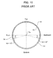
- an upper lubrication groove 53 is formed in the entirely of an upper split metal 51 (the entire length of the half circumference), and lower lubrication grooves 54 are formed in a predetermined range [at about 10 to 15° (circular arc angle with respect to a shaft body center O M ) from a mating plane S] at both ends of a lower split metal 52.
- the above-described lubrication grooves 53, 54 formed in the inner circumferential surface of the bearing metal of the sliding bearing in the diesel engine are formed in the entirety of the upper split metal 51 and in the proximity of both ends of the lower split metal 52, but the problem is that peeling occurs in the vicinity of the mating plane s of the upper and lower split metals 51, 52.
- a bearing metal is a bearing metal that has a vertically split structure composed of an upper split metal and a lower split metal, supports a rotating shaft body, and has a lubrication groove formed in an inner circumferential surface, wherein in a case where the direction of maximum displacement of the rotating shaft body in a plane perpendicular to the rotation axis of the rotating shaft body during the rotation of the rotating shaft body is in the vicinity of the mating plane of the upper and lower split metals, the lubrication groove formed in the circumferential direction on the upper split metal side is not disposed at least in the vicinity of the mating plane, and the lubrication groove formed in the circumferential direction on the lower split metal side is disposed in the vicinity of the mating plane on the opposite side to the direction of maximum displacement.
- a bearing metal according to a second aspect is a bearing metal that has a vertically split structure composed of an upper split metal and a lower split metal, supports a rotating shaft body, and has a lubrication groove formed in an inner circumferential surface, wherein in a case where the direction of maximum displacement of the rotating shaft body in a plane perpendicular to the rotation axis of the rotating shaft body during the rotation of the rotating shaft body is above the mating plane of the upper and lower split metals, the lubrication qroove formed in the circumferential direction on the upper split metal side is not disposed at least from the mating plane in the direction of maximum displacement to an upper portion that is above the vicinity of the mating plane.
- a bearing metal according to a third aspect is a bearing metal that has a vertically split structure composed of an upper split metal and a lower split metal, supports a rotating shaft body, and has a lubrication groove formed in an inner circumferential surface, wherein in a case where the direction of maximum displacement of the rotating shaft body in a plane perpendicular to the rotation axis of the rotating shaft body during the rotation of the rotating shaft body is above the mating plane of the upper and lower split metals, the lubrication groove formed in the circumferential direction on the upper split metal side is not disposed at least from the mating plane in the direction of maximum displacement to an upper portion above the vicinity of the mating plane, and the lubrication groove formed in the circumferential direction on the lower split metal side is disposed in the vicinity of the mating plane on the opposite side to the direction of maximum displacement.
- a bearing metal according to a fourth aspect is the bearing metal according to any one of the first to third aspects, wherein the direction of maximum displacement is within the range in which an eccentricity of the rotating shaft body with respect to the bearing metal is equal to or more than 0.9.
- a bearing metal according to a fifth aspect is the bearing metal according to any one of the first to three aspects, wherein the vicinity of the mating plane is within a range of substantially ⁇ 10° with respect to the mating plane.
- a bearing metal according to a sixth aspect is the bearing metal according to the second or third aspect, wherein the upper portion is within a range that is further substantially 10° from the vicinity of the mating plane.
- the lubrication groove formed in the circumferential direction on the upper split metal side is not disposed at least in the vicinity of the mating plane. Therefore, even when friction heat is generated on the maximum displacement direction side, a lubricating oil is not directly supplied. As a result, thermal strains can be reduced, thereby preventing the occurrence of damage such as peeling in the bearing metal.
- the lubrication groove formed in the circumferential direction on the upper split metal side is not disposed in the upper portion. Therefore, even when friction heat is generated in the direction of maximum displacement, a lubricating oil is not directly supplied. As a result, thermal strains can be reduced in the upper portion, thereby preventing the occurrence of damage such as peeling in the bearing metal.
- a bearing metal according to the preferred embodiment of the present invention will be explained below based on FIGS. 1 to 7 .
- the bearing metal of the present embodiment will be explained which is disposed, for example, on the inner surface of a bearing supporting a crankshaft (also referred to as a main bearing) of a large diesel engine for a ship (so-called the main engine) that is installed in a ship.
- a bearing supporting a crankshaft also referred to as a main bearing
- the main engine a large diesel engine for a ship
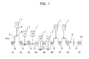
- the engine has, for example, seven pistons 1.
- a crankshaft 2 of the engine is supported by eight (#1 to #8) bearings 3, and the rear end portion thereof on the stern side is supported by a bearing 3 (#9) provided on. a. bulkhead.
- #1 shows the bearing on the bow side (Fore)
- #8 shows the bearing on the stern side (Aft).
- a crank pin 5 is provided by using crank arms 4 in a position corresponding to each piston 1 of the crankshaft 2, and the crank pin 5 and the piston 1 are linked by a connecting rod 6.
- the bearing 3 provided with a bearing metal will be explained below.
- a bearing metal 11 that rotatably supports the journal (an example of a rotating shaft body; it will be referred to hereinbelow as a shaft body and will be denoted by reference numeral 2 the same as that of the crankshaft) of the crankshaft 2 is provided inside the bearing 3.
- the bearing metal 11 has a vertically split structure and is composed of an upper split metal 12 as an upper-half circumferential portion and a lower split metal 13 as a lower-half circumferential portion.
- Upper and lower lubrication grooves 14, 15 of a predetermined width are formed along the circumferential direction in the inner circumferential surfaces of these split metals 12 and 13.
- peeled part does not necessarily coincide with the direction of a force (load) acting upon the shaft body 2 and that the peeling is caused by thermal strains generated as heating induced by friction of the shaft body 2 and bearing metal 11 (so-called friction heat) and cooling induced by the supply of a lubricating oil are repeated.
- the friction heat is considered to be generated by a comparatively large displacement (movement) of the shaft body 2 inside the bearing metal 11 at positions where the oil film is easily ruptured, for example, where the lubricating oil is hardly dragged in, such as a horizontal plane in the proximity of the bearing center and a region above this horizontal plane.
- the position with a large displacement of the shaft body 2 is a position in which the lubricating oil is dragged in and displaced slightly upward in the rotation direction of the shaft body when the shaft body is rotated, and not always a position where the largest load is applied. Taking these factors into account, the position where friction heat is generated is in the vicinity of the so-called mating plane of the bearing 3 and a portion thereabove.
- the lubricating oil may not be supplied directly to the position where the oil film can be easily ruptured, that is, to a mating plane vicinity M that is close to the horizontal plane and a portion N thereabove.
- the methods include a method of actually conducting measurements (referred to hereinbelow as actual measurements) and a method based on the theoretic analysis.
- FIG. 5A shows the results obtained by actually measuring the displacement of the shaft body 2 in #1, #2, #4, and #8 bearings 3
- FIG. 5B shows the results obtained by finding the displacement of the shaft body 2 by the theoretic analysis.
- the displacements shown in FIGS. 5A and 5B indicate the eccentricity.
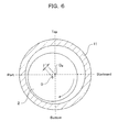
- the eccentricity represents, using a rotation angle ⁇ of the shaft body 2 as a parameter, the displacement direction of the shaft body 2 and a ratio ( ⁇ /c) of a displacement, amount ⁇ of a center O of the shaft body 2 to a radial clearance c of the shaft body 2 with respect to the shaft body 2 and the bearing metal 11 (a radial clearance in a state in which the center O of the shaft body 2 coincides a center O M of the bearing metal 11).
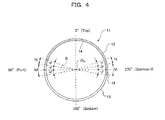
- 0° is represented by "Top", 90° by "Port”, 180° by "Bottom”, and 270° by "starboard”.
- a mating plane (corresponding to the horizontal plane when considered according to the usual disposition state) S of the two split metals 12, 13 represents a plane (in a case where the bearing is disposed correctly, this plane is the horizontal plane) including a left side portion (90°) and a right side portion (270°),
- the mating plane vicinity M represents a range of substantially ⁇ 10° (in other words, a range of 20°; can be also referred to as "a predetermined range”) with respect to the left side portion (90°) or the right side portion (270°), that is, the horizontal plane
- the portion N above the mating plane vicinity M represents a range of substantially 10° (can be also referred to as "a predetermined range") (see FIG. 4 ).
- the range of “substantially” hereinabove is about ⁇ 20%, preferably about ⁇ 10%.
- the angle hereinabove represents a circular arc angle about the center O M of the bearing metal 11 (hereinafter the same).
- the maximum displacement portion position with a large displacement
- friction heat is generated due to contact with the bearing metal
- the lubricating groove is formed in the matting plane vicinity M or the portion N
- thermal strains are induced by the cooling function of the lubricating oil and a peeling phenomenon is observed. Therefore, the peeling phenomenon can be prevented by disposing the lubrication groove so that the lubricating oil is not directly supplied to the maximum displacement portion.
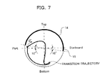
- the upper lubrication groove 14 formed in the circumferential direction on the upper split metal 12 side is not formed at least in the vicinity (at up to about 10°) M of the mating plane
- the lower lubrication groove 15 on the lower split metal 13 side is formed in the vicinity (at down around -10°) M of the mating plane on the opposite side to the direction of maximum displacement.
- the lubrication groove 15 is provided to the vicinity M of the mating plane on the opposite side particularly because it is not necessary to take thermal strains into account.
- the upper lubrication groove 14 formed in the circumferential direction on the upper split metal 12 side is not formed at least to the portion N above the vicinity M of the mating plane in the direction of maximum displacement, or in other words, to an angle of 0° to 20°.
- the lower lubrication groove 15 formed in the circumferential direction on the lower split metal 13 side is formed in the vicinity M of the mating plane on the opposite side to the direction of maximum displacement.
- the displacement trajectory is within a range of substantially 80° to substantially 265°.
- the upper lubrication groove 14 may be formed only on the upper split metal 12 side. Thus, it is not necessary to provided the lubrication groove that is conventionally provided in the lower split metal 13.
- the displacement trajectory is within a range of substantially 100° to substantially 230°.
- the conventional lubrication grooves may be used.
- the displacement trajectory is within a range of substantially 80° to substantially 260°.
- the lubrication grooves 14, 15 may be formed, for example, on the upper split metal 12 side and the right side of the lower split metal 13.
- the displacement trajectory is substantially along the entire circumference, but where only the trajectory with a large eccentricity is considered, the range is from 40° to substantially 180°.
- the upper lubrication groove 14 is not formed, for example, in a portion (in the vicinity of the mating plane) close to the left side portion (90°) of the upper split metal 12, and the lower lubrication groove 15 may be formed in the right side portion of the lower split metal 13.
- the lubrication groove may be provided in the right side portion (270°) of the lower split metal 13, without providing the lubrication groove in the portion close to the left side portion (90°) of the upper split metal 12.
- the lubrication groove is not provided in the range of the vicinity M of the mating plane and the portion N thereabove, wherein the eccentricity of the shaft body 2 is 0.9 or more.
- a measurement method and an analytical method (theoretic analysis) using calculations can be used to find the disposition range of the lubrication groove, that is, the axis behavior range.
- the measurement method requires no explanation, but the analytical method will be briefly explained below.
- a crankshaft system is replaced with a small number of beam elements, while maintaining the configuration of the journal, crank arm, and crank pin, the mobility method of a short bearing solution is used for the lubrication analysis of the bering, and a transmission matrix method is applied to the coupled analysis of shaft system behavior and lubrication analysis This procedure will be explained below in a simple manner.
- the shaft body 2 is displaced in a plane perpendicular to the rotation axis of the shaft body 2 during the rotation of the shaft body 2 and a direction in which the displacement is large, that is, the direction of maximum displacement, is in the vicinity M of the mating plane of the upper and lower split metals 12, 13, the lubrication groove 14 formed in the circumferential direction on the upper split metal 12 side of the bearing metal 11, is not disposed in the vicinity M of the mating plane. Therefore, even when friction heat is generated in the direction of maximum displacement, a lubricating oil is not directly supplied. As a result, thermal strains are reduced and, therefore, the occurrence of damage such as peeling in the bearing metal can be prevented.
- the lower lubrication groove 15 provided in the lower split metal. 13, is formed in the vicinity M of the mating plane on the opposite side to the direction of maximum displacement, for example, within a range of substantially 10°, a lubricating oil is supplied to a portion where friction heat is not generated, and the lubrication function is maintained.
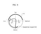
- the upper lubrication groove 14 is not disposed at least in the vicinity M of the mating plane of the upper split metal 12 in the direction of maximum displacement or in the portion N thereabove, but the upper lubrication groove may not also be disposed in the same range on the opposite side, as shown in FIG. 9 . Therefore, in this case, the lubrication groove is not formed in the lower split metal 13.
Landscapes
- Engineering & Computer Science (AREA)
- General Engineering & Computer Science (AREA)
- Mechanical Engineering (AREA)
- Chemical & Material Sciences (AREA)
- Oil, Petroleum & Natural Gas (AREA)
- Sliding-Contact Bearings (AREA)
- Shafts, Cranks, Connecting Bars, And Related Bearings (AREA)
Abstract
Description
- The present invention relates to a bearing metal provided in the bearing of a crankshaft, for example, in the main engine of a ship.
- A sliding bearing is usually used as a bearing that supports a journal (referred to hereinbelow as "a shaft body") of a crankshaft of a large diesel engine that is the main engine of a ship. A bearing metal having a vertically split structure composed of an upper split metal and a lower split metal is provided on the inside of the sliding bearing, and a lubrication groove is obviously formed in the bearing metal.
- The formation range of the lubrication groove of this type is as follows. As shown in
FIG. 10 , anupper lubrication groove 53 is formed in the entirely of an upper split metal 51 (the entire length of the half circumference), andlower lubrication grooves 54 are formed in a predetermined range [at about 10 to 15° (circular arc angle with respect to a shaft body center OM) from a mating plane S] at both ends of alower split metal 52. - The above-described
lubrication grooves upper split metal 51 and in the proximity of both ends of thelower split metal 52, but the problem is that peeling occurs in the vicinity of the mating plane s of the upper andlower split metals - Accordingly, it is an object of the present invention to provide a bearing metal that can prevent the occurrence of peeling.
- In order to resolve the above-described problem, a bearing metal according to a first aspect of the present invention is a bearing metal that has a vertically split structure composed of an upper split metal and a lower split metal, supports a rotating shaft body, and has a lubrication groove formed in an inner circumferential surface, wherein
in a case where the direction of maximum displacement of the rotating shaft body in a plane perpendicular to the rotation axis of the rotating shaft body during the rotation of the rotating shaft body is in the vicinity of the mating plane of the upper and lower split metals, the lubrication groove formed in the circumferential direction on the upper split metal side is not disposed at least in the vicinity of the mating plane, and
the lubrication groove formed in the circumferential direction on the lower split metal side is disposed in the vicinity of the mating plane on the opposite side to the direction of maximum displacement. - A bearing metal according to a second aspect is a bearing metal that has a vertically split structure composed of an upper split metal and a lower split metal, supports a rotating shaft body, and has a lubrication groove formed in an inner circumferential surface, wherein
in a case where the direction of maximum displacement of the rotating shaft body in a plane perpendicular to the rotation axis of the rotating shaft body during the rotation of the rotating shaft body is above the mating plane of the upper and lower split metals, the lubrication qroove formed in the circumferential direction on the upper split metal side is not disposed at least from the mating plane in the direction of maximum displacement to an upper portion that is above the vicinity of the mating plane. - A bearing metal according to a third aspect is a bearing metal that has a vertically split structure composed of an upper split metal and a lower split metal, supports a rotating shaft body, and has a lubrication groove formed in an inner circumferential surface, wherein
in a case where the direction of maximum displacement of the rotating shaft body in a plane perpendicular to the rotation axis of the rotating shaft body during the rotation of the rotating shaft body is above the mating plane of the upper and lower split metals, the lubrication groove formed in the circumferential direction on the upper split metal side is not disposed at least from the mating plane in the direction of maximum displacement to an upper portion above the vicinity of the mating plane, and
the lubrication groove formed in the circumferential direction on the lower split metal side is disposed in the vicinity of the mating plane on the opposite side to the direction of maximum displacement. - A bearing metal according to a fourth aspect is the bearing metal according to any one of the first to third aspects, wherein the direction of maximum displacement is within the range in which an eccentricity of the rotating shaft body with respect to the bearing metal is equal to or more than 0.9.
- A bearing metal according to a fifth aspect is the bearing metal according to any one of the first to three aspects, wherein the vicinity of the mating plane is within a range of substantially ±10° with respect to the mating plane.
- A bearing metal according to a sixth aspect is the bearing metal according to the second or third aspect, wherein the upper portion is within a range that is further substantially 10° from the vicinity of the mating plane.
- With the configuration of the bearing metal according to the first aspect, in the case where the rotating shaft body is displaced in the plane perpendicular to the rotation axis of the rotating shaft body during the rotation of the rotating shaft body and the direction of maximum displacement is in the vicinity of the mating plane of the upper a.nd lower split metals, the lubrication groove formed in the circumferential direction on the upper split metal side is not disposed at least in the vicinity of the mating plane. Therefore, even when friction heat is generated on the maximum displacement direction side, a lubricating oil is not directly supplied. As a result, thermal strains can be reduced, thereby preventing the occurrence of damage such as peeling in the bearing metal.
- With the configuration of the bearing metal according to the second and third aspects, in the case where the rotating shaft body is displaced in the plane perpendicular to the rotation axis of the rotating shaft body during the rotation of the rotating shaft body and the direction of maximum displacement is above the vicinity of the mating plane of the upper and lower split metals, the lubrication groove formed in the circumferential direction on the upper split metal side is not disposed in the upper portion. Therefore, even when friction heat is generated in the direction of maximum displacement, a lubricating oil is not directly supplied. As a result, thermal strains can be reduced in the upper portion, thereby preventing the occurrence of damage such as peeling in the bearing metal.
-
-
FIG. 1 is a schematic view of an engine provided with a bearing having a bearing metal according to an embodiment of the present invention. -
FIG. 2 is a perspective view of the bearing metal according to the embodiment. -
FIG. 3 is an exploded perspective view according to the embodiment. -
FIG. 4 is a side view illustrating the disposition range of a lubrication groove in the bearing metal according to the embodiment. -
FIG. 5A shows actually measured values relating to the displacement state of a rotating shaft body with respect to the bearing metal according to the embodiment. -
FIG. 5B shows theoretical analysis values relating to the displacement state of the rotating shaft body with respect to the bearing metal according to the embodiment. -
FIG. 6 is a cross-sectional view illustrating the eccentricity of the rotating shaft body with respect to the bearing metal according to the embodiment. -
FIG. 7 is a schematic side view illustrating the disposition state of the lubrication groove of the bearing metal according to the embodiment. -
FIG. 8 is a schematic side view illustrating the disposition state of a lubrication groove of a bearing metal of another embodiment of the present invention. -
FIG. 9 is a schematic side view illustrating the disposition state of a lubrication groove of a bearing metal of another embodiment of the present invention. -
FIG. 10 is a cross-sectional view of a bearing metal of the conventional example. - A bearing metal according to the preferred embodiment of the present invention will be explained below based on
FIGS. 1 to 7 . - The bearing metal of the present embodiment will be explained which is disposed, for example, on the inner surface of a bearing supporting a crankshaft (also referred to as a main bearing) of a large diesel engine for a ship (so-called the main engine) that is installed in a ship.
- The configuration of the engine will be schematically explained below. As shown in
FIG. 1 , the engine has, for example, sevenpistons 1. Acrankshaft 2 of the engine is supported by eight (#1 to #8)bearings 3, and the rear end portion thereof on the stern side is supported by a bearing 3 (#9) provided on. a. bulkhead. Here, #1 shows the bearing on the bow side (Fore) and #8 shows the bearing on the stern side (Aft). It goes without saying that acrank pin 5 is provided by usingcrank arms 4 in a position corresponding to eachpiston 1 of thecrankshaft 2, and thecrank pin 5 and thepiston 1 are linked by aconnecting rod 6. - The
bearing 3 provided with a bearing metal will be explained below. - As shown in
FIG. 2 and FIG. 3 , a bearingmetal 11 that rotatably supports the journal (an example of a rotating shaft body; it will be referred to hereinbelow as a shaft body and will be denoted byreference numeral 2 the same as that of the crankshaft) of thecrankshaft 2 is provided inside thebearing 3. - The
bearing metal 11 has a vertically split structure and is composed of anupper split metal 12 as an upper-half circumferential portion and alower split metal 13 as a lower-half circumferential portion. - Upper and
lower lubrication grooves split metals - Basic considerations taken into account when the lubrication grooves of the bearing metal are formed (disposed) will be explained below.
- The results obtained by examining the peeling state of the bearing
metal 11 demonstrates that the peeled part (peeled region) does not necessarily coincide with the direction of a force (load) acting upon theshaft body 2 and that the peeling is caused by thermal strains generated as heating induced by friction of theshaft body 2 and bearing metal 11 (so-called friction heat) and cooling induced by the supply of a lubricating oil are repeated. - The friction heat is considered to be generated by a comparatively large displacement (movement) of the
shaft body 2 inside the bearingmetal 11 at positions where the oil film is easily ruptured, for example, where the lubricating oil is hardly dragged in, such as a horizontal plane in the proximity of the bearing center and a region above this horizontal plane. Further, as mentioned hereinabove, the position with a large displacement of theshaft body 2 is a position in which the lubricating oil is dragged in and displaced slightly upward in the rotation direction of the shaft body when the shaft body is rotated, and not always a position where the largest load is applied. Taking these factors into account, the position where friction heat is generated is in the vicinity of the so-called mating plane of thebearing 3 and a portion thereabove. - Therefore, in order to prevent peeling, as shown in
FIG. 4 , the lubricating oil may not be supplied directly to the position where the oil film can be easily ruptured, that is, to a mating plane vicinity M that is close to the horizontal plane and a portion N thereabove. - Thus, by measuring the displacement of the
shaft body 2 or conducting a theoretic analysis of the behavior of theshaft body 2 during the rotation of theshaft body 2, it is possible to discover the position with a large displacement (referred to hereinbelow as a direction of maximum displacement) of theshaft body 2 in the mating plane vicinity M and the portion N thereabove, and the methods include a method of actually conducting measurements (referred to hereinbelow as actual measurements) and a method based on the theoretic analysis. - For example,
FIG. 5A shows the results obtained by actually measuring the displacement of theshaft body 2 in #1, #2, #4, and #8bearings 3, andFIG. 5B shows the results obtained by finding the displacement of theshaft body 2 by the theoretic analysis. The displacements shown inFIGS. 5A and 5B indicate the eccentricity. - As shown in
FIG. 6 , the eccentricity represents, using a rotation angle θ of theshaft body 2 as a parameter, the displacement direction of theshaft body 2 and a ratio (δ/c) of a displacement, amount δ of a center O of theshaft body 2 to a radial clearance c of theshaft body 2 with respect to theshaft body 2 and the bearing metal 11 (a radial clearance in a state in which the center O of theshaft body 2 coincides a center OM of the bearing metal 11). InFIG. 5A and FIG. 5B , 0° is represented by "Top", 90° by "Port", 180° by "Bottom", and 270° by "starboard". - In the explanation below, a mating plane (corresponding to the horizontal plane when considered according to the usual disposition state) S of the two split
metals FIG. 4 ). The range of "substantially" hereinabove is about ±20%, preferably about ±10%. The angle hereinabove represents a circular arc angle about the center OM of the bearing metal 11 (hereinafter the same). - Both the actual measurement results and the analytical results shown in
FIG. 5A and FIG. 5B indicate that the maximum displacement portion (more specifically, a portion with an eccentricity of 0.9 or more) appears in the vicinity M of the mating plane of theupper split metal 14 andlower split metal 15 and that in the #8bearing 3, this portion appears in the mating plane vicinity M and the portion N thereabove. These results clearly correspond to the peeled part in the conventional bearing metal - Thus, when the maximum displacement portion (position with a large displacement) is situated in the mating plane vicinity M or the portion N thereabove, friction heat is generated due to contact with the bearing metal, and when the lubricating groove is formed in the matting plane vicinity M or the portion N, thermal strains are induced by the cooling function of the lubricating oil and a peeling phenomenon is observed. Therefore, the peeling phenomenon can be prevented by disposing the lubrication groove so that the lubricating oil is not directly supplied to the maximum displacement portion.
- In summary, in a case where the
shaft body 2 is displaced in a plane perpendicular to a rotation axis during the rotation of theshaft body 2, as shown inFIG. 7 , and the direction of maximum displacement of the rotating shaft body is in the vicinity M of the mating plane of the upper andlower split metals upper lubrication groove 14 formed in the circumferential direction on theupper split metal 12 side is not formed at least in the vicinity (at up to about 10°) M of the mating plane, and thelower lubrication groove 15 on thelower split metal 13 side is formed in the vicinity (at down around -10°) M of the mating plane on the opposite side to the direction of maximum displacement. Thelubrication groove 15 is provided to the vicinity M of the mating plane on the opposite side particularly because it is not necessary to take thermal strains into account. - Further, in a case where the
shaft body 2 is displaced in the plane perpendicular to the rotation axis during the rotation of theshaft body 2 and the direction of maximum displacement of the rotating shaft body is above the mating plane S of the upper andlower split metals upper lubrication groove 14 formed in the circumferential direction on theupper split metal 12 side is not formed at least to the portion N above the vicinity M of the mating plane in the direction of maximum displacement, or in other words, to an angle of 0° to 20°. Thelower lubrication groove 15 formed in the circumferential direction on thelower split metal 13 side is formed in the vicinity M of the mating plane on the opposite side to the direction of maximum displacement. - The disposition ranges of the lubrication grooves will be described below more specifically with reference to
FIG. 5A and FIG. 5B . - In the #1
bearing 3, the displacement trajectory is within a range of substantially 80° to substantially 265°. In this case, theupper lubrication groove 14 may be formed only on theupper split metal 12 side. Thus, it is not necessary to provided the lubrication groove that is conventionally provided in thelower split metal 13. - In the #2
bearing 3, the displacement trajectory is within a range of substantially 100° to substantially 230°. In this case, the conventional lubrication grooves may be used. - In the #4
bearing 3, the displacement trajectory is within a range of substantially 80° to substantially 260°. In this case, thelubrication grooves upper split metal 12 side and the right side of thelower split metal 13. - In the #8
bearing 3, the displacement trajectory is substantially along the entire circumference, but where only the trajectory with a large eccentricity is considered, the range is from 40° to substantially 180°. In this case, theupper lubrication groove 14 is not formed, for example, in a portion (in the vicinity of the mating plane) close to the left side portion (90°) of theupper split metal 12, and thelower lubrication groove 15 may be formed in the right side portion of thelower split metal 13. - Therefore, the lubrication groove may be provided in the right side portion (270°) of the
lower split metal 13, without providing the lubrication groove in the portion close to the left side portion (90°) of theupper split metal 12. - Thus, to explain the disposition ra.nge (formation range) of the lubrication groove, the lubrication groove is not provided in the range of the vicinity M of the mating plane and the portion N thereabove, wherein the eccentricity of the
shaft body 2 is 0.9 or more. - A measurement method and an analytical method (theoretic analysis) using calculations can be used to find the disposition range of the lubrication groove, that is, the axis behavior range. The measurement method requires no explanation, but the analytical method will be briefly explained below. A crankshaft system is replaced with a small number of beam elements, while maintaining the configuration of the journal, crank arm, and crank pin, the mobility method of a short bearing solution is used for the lubrication analysis of the bering, and a transmission matrix method is applied to the coupled analysis of shaft system behavior and lubrication analysis This procedure will be explained below in a simple manner.
-
- (1) First, the inclination of the journal and a bearing load applied to the bearing at a crank angle of 0° are found by a transmission matrix method.
-
- (2) Then, a bearing load is calculated from the displacement amount of the bearing and the eccentricity of the journal is found by a mobility method.
-
- (3) Then, the obtained eccentricity is used in transmission matrix calculations, and the inclination of the journal and a bearing load at the next crank angle step are found.
-
- (4) Finally, the operations (1) to (3) described above are repeated over one cycle, and the repetition may continue till the difference between the eccentricity amount at a crank angle of 0° and the eccentricity amount at a crank angle of 360° becomes no more than a certain set value. Usually a sufficient convergence is achieved in three to four repetitions.
- By the above-described procedure, shaft inclinations or eccentricities of the shaft bodies (journals) in all the bearings within one cycle are found.
- Thus, in the case where the
shaft body 2 is displaced in a plane perpendicular to the rotation axis of theshaft body 2 during the rotation of theshaft body 2 and a direction in which the displacement is large, that is, the direction of maximum displacement, is in the vicinity M of the mating plane of the upper andlower split metals lubrication groove 14 formed in the circumferential direction on theupper split metal 12 side of the bearingmetal 11, is not disposed in the vicinity M of the mating plane. Therefore, even when friction heat is generated in the direction of maximum displacement, a lubricating oil is not directly supplied. As a result, thermal strains are reduced and, therefore, the occurrence of damage such as peeling in the bearing metal can be prevented. In this case, thelower lubrication groove 15 provided in the lower split metal. 13, is formed in the vicinity M of the mating plane on the opposite side to the direction of maximum displacement, for example, within a range of substantially 10°, a lubricating oil is supplied to a portion where friction heat is not generated, and the lubrication function is maintained. - In the above-described embodiment, in the case where the direction of maximum displacement of the rotating shaft body is in the vicinity M of the mating plane or the portion N thereabove, the
upper lubrication groove 14 is not disposed at least in the vicinity M of the mating plane of theupper split metal 12 in the direction of maximum displacement or in the portion N thereabove, but the upper lubrication groove may not also be disposed in the same range on the opposite side, as shown inFIG. 9 . Therefore, in this case, the lubrication groove is not formed in thelower split metal 13.
Claims (6)
- A bearing metal that has a vertically split structure composed of an upper split metal and a lower split metal, supports a rotating shaft body, and has a lubrication groove formed in an inner circumferential surface, wherein
in a case where a direction of maximum displacement of the rotating shaft body in a plane perpendicular to a rotation axis of the rotating shaft body during rotation of the rotating shaft body is in a vicinity of a mating plane of the upper and lower split metals, the lubrication groove formed in a circumferential direction on the upper split metal side is not disposed at least in the vicinity of the mating plane, and
the lubrication groove formed in the circumferential direction on the lower split metal side is disposed in the vicinity of the mating plane on an opposite side to the direction of maximum displacement. - A bearing metal that has a vertically split structure composed of an upper split metal and a lower split metal, supports a rotating shaft body, and has a lubrication groove formed in an inner circumferential surface, wherein
in a case where a direction of maximum displacement of the rotating shaft body in a plane perpendicular to a rotation axis of the rotating shaft body duping rotation of the rotating shaft body is above a mating plane of the upper and lower split metals, the lubrication groove formed in a circumferential direction on an upper split metal side is not disposed at least from the mating plane in the direction of maximum displacement to an upper portion above a vicinity of the mating plane. - A bearing metal that has a vertically split structure composed of an upper split metal and a lower split metal, supports a rotating shaft body, and has a lubrication groove formed in an inner circumferential surface, wherein
in a case where a direction of maximum displacement of the rotating shaft body in a plane perpendicular to a rotation axis of the rotating shaft body during rotation of the rotating shaft body is above a mating plane of the upper and lower split metals, the lubrication groove formed in a circumferential direction on an upper split metal side is not disposed at least from the mating plane in the direction of maximum displacement to an upper portion above a vicinity of the mating plane, and
the lubrication groove formed in the circumferential direction on a lower split metal side is disposed in the vicinity of the mating plane on an opposite side to the direction of maximum displacement. - The bearing metal according to any one of claims 1 to 3, wherein the direction of maximum displacement is within a range in which an eccentricity of the rotating shaft body with respect to the bearing metal is equal to or more than 0.9.
- The bearing metal according to any one of claims 1 to 3, wherein the vicinity of the mating plane is within a range of substantially ±10° with respect to the mating plane.
- The bearing metal according to claim 2 or 3, wherein the upper portion is within a range that is further substantially 10° from the vicinity of the mating plane.
Applications Claiming Priority (2)
| Application Number | Priority Date | Filing Date | Title |
|---|---|---|---|
| JP2007131102A JP5084346B2 (en) | 2007-05-17 | 2007-05-17 | Bearing metal |
| PCT/JP2008/001131 WO2008142830A1 (en) | 2007-05-17 | 2008-05-01 | Bearing metal |
Publications (2)
| Publication Number | Publication Date |
|---|---|
| EP2159434A1 true EP2159434A1 (en) | 2010-03-03 |
| EP2159434A4 EP2159434A4 (en) | 2012-09-26 |
Family
ID=40031550
Family Applications (1)
| Application Number | Title | Priority Date | Filing Date |
|---|---|---|---|
| EP08751656A Withdrawn EP2159434A4 (en) | 2007-05-17 | 2008-05-01 | CARRYING METAL |
Country Status (6)
| Country | Link |
|---|---|
| US (1) | US20100119182A1 (en) |
| EP (1) | EP2159434A4 (en) |
| JP (1) | JP5084346B2 (en) |
| KR (1) | KR20100014376A (en) |
| CN (1) | CN101636596B (en) |
| WO (1) | WO2008142830A1 (en) |
Cited By (1)
| Publication number | Priority date | Publication date | Assignee | Title |
|---|---|---|---|---|
| EP4130500B1 (en) * | 2021-08-02 | 2024-06-19 | Kabushiki Kaisha Kobe Seiko Sho (Kobe Steel, Ltd.) | Bearing device and method for driving bearing device |
Families Citing this family (3)
| Publication number | Priority date | Publication date | Assignee | Title |
|---|---|---|---|---|
| JP5837896B2 (en) * | 2013-03-21 | 2015-12-24 | 大豊工業株式会社 | Plain bearing |
| NL2013448B1 (en) * | 2014-09-10 | 2016-09-05 | Daf Trucks Nv | Crankshaft and main bearing assembly for a reciprocating piston internal combustion engine. |
| JP6533049B2 (en) * | 2014-11-04 | 2019-06-19 | 大豊工業株式会社 | Half bearing |
Family Cites Families (10)
| Publication number | Priority date | Publication date | Assignee | Title |
|---|---|---|---|---|
| US2030232A (en) * | 1933-08-21 | 1936-02-11 | Gen Motors Corp | Bearing lubrication |
| DE1576354A1 (en) * | 1967-03-11 | 1970-04-16 | Daimler Benz Ag | Base bearing of an internal combustion engine |
| US4235481A (en) * | 1977-11-16 | 1980-11-25 | Taiho Kogyo Co., Ltd. | Bearing device for internal combustion engine |
| JPS5962721A (en) * | 1982-09-30 | 1984-04-10 | Taiho Kogyo Co Ltd | Internal combustion engine bearing device |
| JPH07139539A (en) * | 1993-11-17 | 1995-05-30 | Ndc Co Ltd | Main shaft supporting structure |
| JPH1030419A (en) * | 1996-07-17 | 1998-02-03 | Nippon Soken Inc | Bearing device for internal combustion engine |
| DE10105542A1 (en) * | 2001-02-07 | 2002-08-29 | Porsche Ag | Lube oil supply for the connecting rod bearings of a crankshaft of a multi-cylinder internal combustion engine |
| DE60322933D1 (en) * | 2002-10-24 | 2008-09-25 | Taiho Kogyo Co Ltd | OIL FEEDING DEVICE FOR MOTOR CRANKSHAFT |
| JP2005249024A (en) * | 2004-03-03 | 2005-09-15 | Daido Metal Co Ltd | Slide bearing |
| JP4725480B2 (en) * | 2006-10-12 | 2011-07-13 | トヨタ自動車株式会社 | Slide bearing, and torque transmission device and engine having the same |
-
2007
- 2007-05-17 JP JP2007131102A patent/JP5084346B2/en not_active Expired - Fee Related
-
2008
- 2008-05-01 WO PCT/JP2008/001131 patent/WO2008142830A1/en not_active Ceased
- 2008-05-01 KR KR1020097016298A patent/KR20100014376A/en not_active Ceased
- 2008-05-01 US US12/451,030 patent/US20100119182A1/en not_active Abandoned
- 2008-05-01 EP EP08751656A patent/EP2159434A4/en not_active Withdrawn
- 2008-05-01 CN CN200880007799XA patent/CN101636596B/en not_active Expired - Fee Related
Cited By (1)
| Publication number | Priority date | Publication date | Assignee | Title |
|---|---|---|---|---|
| EP4130500B1 (en) * | 2021-08-02 | 2024-06-19 | Kabushiki Kaisha Kobe Seiko Sho (Kobe Steel, Ltd.) | Bearing device and method for driving bearing device |
Also Published As
| Publication number | Publication date |
|---|---|
| US20100119182A1 (en) | 2010-05-13 |
| JP5084346B2 (en) | 2012-11-28 |
| KR20100014376A (en) | 2010-02-10 |
| JP2008286291A (en) | 2008-11-27 |
| CN101636596A (en) | 2010-01-27 |
| EP2159434A4 (en) | 2012-09-26 |
| WO2008142830A1 (en) | 2008-11-27 |
| CN101636596B (en) | 2012-02-01 |
Similar Documents
| Publication | Publication Date | Title |
|---|---|---|
| US8393792B2 (en) | Bearing device | |
| JP5340697B2 (en) | Sliding bearing for internal combustion engine and sliding bearing device | |
| EP2290250A2 (en) | Bearing cartridge | |
| AU2002216738A1 (en) | Flange bearing | |
| US20100119182A1 (en) | Bearing metal | |
| US20050201647A1 (en) | Half plain bearing | |
| WO2009142172A1 (en) | Halved outer ring, halved rolling bearing using the same, and structure and method of mounting rolling bearing | |
| EP1908971A2 (en) | Thrust bearing device | |
| JPH1030419A (en) | Bearing device for internal combustion engine | |
| KR20170077310A (en) | Radial air bearing | |
| CN106164508B (en) | Friction-minimized sliding bearing arrangement | |
| EP0997656A2 (en) | Bearings | |
| JP2007225079A (en) | Sliding bearing for diagonal split type connecting rod | |
| JP2011208691A (en) | Sliding bearing | |
| FI122894B (en) | Piston bearing arrangement | |
| WO2008075567A1 (en) | Slide bearing for engine | |
| Singh et al. | Performance characteristics of an ungrooved big-end bearing with misalignment | |
| US20120160207A1 (en) | Bearing shell with improved side load capability | |
| JP4366590B2 (en) | Engine oil passage structure | |
| US20160153396A1 (en) | Cylinder block having different amount of oil supply for each journal | |
| WO2003098044A1 (en) | Crankshaft, in particular for compressor | |
| JP7520784B2 (en) | SLIDE MEMBER AND METHOD FOR MANUFACTURING SLIDE MEMBER | |
| WO2015140735A1 (en) | Friction minimized crank-drive | |
| JP5603616B2 (en) | Engine and engine lower metal shortage inspection method | |
| US20150252838A1 (en) | Outboard motor |
Legal Events
| Date | Code | Title | Description |
|---|---|---|---|
| PUAI | Public reference made under article 153(3) epc to a published international application that has entered the european phase |
Free format text: ORIGINAL CODE: 0009012 |
|
| 17P | Request for examination filed |
Effective date: 20091217 |
|
| AK | Designated contracting states |
Kind code of ref document: A1 Designated state(s): AT BE BG CH CY CZ DE DK EE ES FI FR GB GR HR HU IE IS IT LI LT LU LV MC MT NL NO PL PT RO SE SI SK TR |
|
| AX | Request for extension of the european patent |
Extension state: AL BA MK RS |
|
| DAX | Request for extension of the european patent (deleted) | ||
| A4 | Supplementary search report drawn up and despatched |
Effective date: 20120827 |
|
| RIC1 | Information provided on ipc code assigned before grant |
Ipc: F16C 17/02 20060101ALI20120821BHEP Ipc: F16C 33/10 20060101ALI20120821BHEP Ipc: F16C 9/02 20060101AFI20120821BHEP |
|
| STAA | Information on the status of an ep patent application or granted ep patent |
Free format text: STATUS: THE APPLICATION IS DEEMED TO BE WITHDRAWN |
|
| 18D | Application deemed to be withdrawn |
Effective date: 20130326 |