EP2159398B1 - Conduite d'entrée résistante à la séparation pour cadres moyennes de turbines - Google Patents
Conduite d'entrée résistante à la séparation pour cadres moyennes de turbines Download PDFInfo
- Publication number
- EP2159398B1 EP2159398B1 EP09252017.0A EP09252017A EP2159398B1 EP 2159398 B1 EP2159398 B1 EP 2159398B1 EP 09252017 A EP09252017 A EP 09252017A EP 2159398 B1 EP2159398 B1 EP 2159398B1
- Authority
- EP
- European Patent Office
- Prior art keywords
- duct
- mid
- turbine
- assembly
- downstream
- Prior art date
- Legal status (The legal status is an assumption and is not a legal conclusion. Google has not performed a legal analysis and makes no representation as to the accuracy of the status listed.)
- Active
Links
- 238000000926 separation method Methods 0.000 title description 5
- 230000007423 decrease Effects 0.000 claims description 2
- 239000007789 gas Substances 0.000 description 13
- 239000000567 combustion gas Substances 0.000 description 4
- 238000009792 diffusion process Methods 0.000 description 2
- 239000012530 fluid Substances 0.000 description 2
- 230000015572 biosynthetic process Effects 0.000 description 1
- 238000010276 construction Methods 0.000 description 1
- 239000007769 metal material Substances 0.000 description 1
- 229910000601 superalloy Inorganic materials 0.000 description 1
Images
Classifications
-
- F—MECHANICAL ENGINEERING; LIGHTING; HEATING; WEAPONS; BLASTING
- F02—COMBUSTION ENGINES; HOT-GAS OR COMBUSTION-PRODUCT ENGINE PLANTS
- F02C—GAS-TURBINE PLANTS; AIR INTAKES FOR JET-PROPULSION PLANTS; CONTROLLING FUEL SUPPLY IN AIR-BREATHING JET-PROPULSION PLANTS
- F02C7/00—Features, components parts, details or accessories, not provided for in, or of interest apart form groups F02C1/00 - F02C6/00; Air intakes for jet-propulsion plants
- F02C7/20—Mounting or supporting of plant; Accommodating heat expansion or creep
-
- F—MECHANICAL ENGINEERING; LIGHTING; HEATING; WEAPONS; BLASTING
- F01—MACHINES OR ENGINES IN GENERAL; ENGINE PLANTS IN GENERAL; STEAM ENGINES
- F01D—NON-POSITIVE DISPLACEMENT MACHINES OR ENGINES, e.g. STEAM TURBINES
- F01D25/00—Component parts, details, or accessories, not provided for in, or of interest apart from, other groups
- F01D25/30—Exhaust heads, chambers, or the like
-
- F—MECHANICAL ENGINEERING; LIGHTING; HEATING; WEAPONS; BLASTING
- F01—MACHINES OR ENGINES IN GENERAL; ENGINE PLANTS IN GENERAL; STEAM ENGINES
- F01D—NON-POSITIVE DISPLACEMENT MACHINES OR ENGINES, e.g. STEAM TURBINES
- F01D5/00—Blades; Blade-carrying members; Heating, heat-insulating, cooling or antivibration means on the blades or the members
- F01D5/12—Blades
- F01D5/14—Form or construction
- F01D5/141—Shape, i.e. outer, aerodynamic form
- F01D5/142—Shape, i.e. outer, aerodynamic form of the blades of successive rotor or stator blade-rows
- F01D5/143—Contour of the outer or inner working fluid flow path wall, i.e. shroud or hub contour
-
- F—MECHANICAL ENGINEERING; LIGHTING; HEATING; WEAPONS; BLASTING
- F01—MACHINES OR ENGINES IN GENERAL; ENGINE PLANTS IN GENERAL; STEAM ENGINES
- F01D—NON-POSITIVE DISPLACEMENT MACHINES OR ENGINES, e.g. STEAM TURBINES
- F01D5/00—Blades; Blade-carrying members; Heating, heat-insulating, cooling or antivibration means on the blades or the members
- F01D5/12—Blades
- F01D5/14—Form or construction
- F01D5/141—Shape, i.e. outer, aerodynamic form
- F01D5/145—Means for influencing boundary layers or secondary circulations
-
- F—MECHANICAL ENGINEERING; LIGHTING; HEATING; WEAPONS; BLASTING
- F01—MACHINES OR ENGINES IN GENERAL; ENGINE PLANTS IN GENERAL; STEAM ENGINES
- F01D—NON-POSITIVE DISPLACEMENT MACHINES OR ENGINES, e.g. STEAM TURBINES
- F01D9/00—Stators
- F01D9/02—Nozzles; Nozzle boxes; Stator blades; Guide conduits, e.g. individual nozzles
- F01D9/023—Transition ducts between combustor cans and first stage of the turbine in gas-turbine engines; their cooling or sealings
-
- F—MECHANICAL ENGINEERING; LIGHTING; HEATING; WEAPONS; BLASTING
- F01—MACHINES OR ENGINES IN GENERAL; ENGINE PLANTS IN GENERAL; STEAM ENGINES
- F01D—NON-POSITIVE DISPLACEMENT MACHINES OR ENGINES, e.g. STEAM TURBINES
- F01D9/00—Stators
- F01D9/02—Nozzles; Nozzle boxes; Stator blades; Guide conduits, e.g. individual nozzles
- F01D9/04—Nozzles; Nozzle boxes; Stator blades; Guide conduits, e.g. individual nozzles forming ring or sector
- F01D9/041—Nozzles; Nozzle boxes; Stator blades; Guide conduits, e.g. individual nozzles forming ring or sector using blades
-
- Y—GENERAL TAGGING OF NEW TECHNOLOGICAL DEVELOPMENTS; GENERAL TAGGING OF CROSS-SECTIONAL TECHNOLOGIES SPANNING OVER SEVERAL SECTIONS OF THE IPC; TECHNICAL SUBJECTS COVERED BY FORMER USPC CROSS-REFERENCE ART COLLECTIONS [XRACs] AND DIGESTS
- Y02—TECHNOLOGIES OR APPLICATIONS FOR MITIGATION OR ADAPTATION AGAINST CLIMATE CHANGE
- Y02T—CLIMATE CHANGE MITIGATION TECHNOLOGIES RELATED TO TRANSPORTATION
- Y02T50/00—Aeronautics or air transport
- Y02T50/60—Efficient propulsion technologies, e.g. for aircraft
Definitions
- the present invention relates to ducts for gas turbine engines, and more particularly to configurations of mid-turbine frame ducts for gas turbine engines.
- a mid-turbine frame is utilized between turbine stages, such as between a high-pressure turbine (HPT) stage and a low-pressure turbine (LPT) stage.
- the mid-turbine frame includes a vane that guides combustion gases as they pass through the duct.
- the vane can comprise or envelop a strut that provides engine structural support that can be used, for instance, to connect the gas turbine engine to an aircraft.
- a flowpath radial offset is desired, with the radial offset initiated as close as possible downstream of the HPT blades.
- an annular duct formed at the mid-turbine frame induces a radial offset of combustion gases passing between the HPT and LPT stages, that is, an increase in radius in the downstream direction.
- a problem encountered with mid-turbine frames is the tendency for the radial offset of the duct to cause flow diffusion.
- Flow diffusion can cause combustion gas flow in the duct to separate from boundary wall surfaces of the duct, causing fluid mixing and relatively high aerodynamic losses. It is desirable to reduce such flow separation and reduce aerodynamic losses.
- US 3704075 discloses a turbine engine having a bearing frame and a turbine nozzle being integrally formed to provide a continuous annular passage.
- EP 1340902 discloses an aircraft engine with an inter-turbine frame including radially spaced apart radially outer first and inner second structural rings disposed co-axially about a centerline.
- the present invention provides a mid-turbine duct assembly for a gas turbine engine, the assembly comprising: a duct defining a generally annular flowpath, the duct comprising a forward duct region that defines an increasing annular flowpath radius in a downstream direction; and characterised in that: the duct comprises a downstream duct region located adjacent to and rearward of the forward duct region, wherein the downstream duct region defines a bulge extending into the generally annular flowpath; and the assembly comprises a mid-turbine frame vane positioned at the downstream duct region, wherein a leading edge of the mid-turbine frame vane is positioned at the bulge in the downstream duct region.
- the present invention provides a mid-turbine frame assembly for a gas turbine engine that includes a generally annular duct configured to reduce flow separation along a surface of the duct.
- flow separation is reduced by providing a radially-outwardly extending bulge along a radially inner flowpath surface of the duct at or near a leading edge of an airfoil portion of a mid-turbine frame vane.
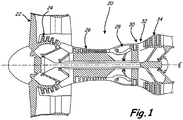
- FIG. 1 is a schematic cross-sectional view of an exemplary two-spool gas turbine engine 20.
- the engine 20 includes a fan 22, a low-pressure compressor (LPC) section 24, a high-pressure compressor (HPC) section 26, a combustor assembly 28, a high-pressure turbine (HPT) section 30, a mid-turbine frame 32, and a low-pressure turbine (LPT) section 34 all arranged about an engine centerline C L .
- LPC low-pressure compressor
- HPC high-pressure compressor
- HPT high-pressure turbine
- LPT low-pressure turbine
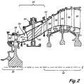
- FIG. 2 is a cross-sectional view of a portion of the gas turbine engine 20 near the mid-turbine frame 32.
- the HPT section 30 includes a number of rotating blades 40 and a number of non-rotating vanes 42
- the LPT section 34 includes a number of rotating, shrouded blades 44 and a number of non-rotating vanes 46.
- the mid-turbine frame assembly 32 includes a duct 50, a number of non-rotating vanes 52 (only one vane 52, shown in partial cross-section is visible in FIG. 2 ), and a strut 54.
- the components of the mid-turbine frame assembly can be formed of a metallic material, such as a nickel- or cobalt-base superalloy.
- the duct 50 includes an inner diameter wall surface 56 and an outer diameter wall surface 58.
- a generally annular combustion gas flowpath is defined between the inner and outer diameter wall surfaces 56 and 58 of the duct 50 about the engine centerline C L .
- the inner and outer diameter wall surfaces 56 and 58 of the duct 50 define a radial offset in the flowpath, whereby the flowpath moves radially outward in the downstream direction. It is generally desired to provide a maximum radial offset in the shortest axial distance.
- rolloff which is a limiting factor on the radial offset of the duct 50.
- the duct 50 can be formed from a plurality of discrete sections positioned adjacent one another (e.g., circumferentially, axially, etc.) to form the generally annular flowpath.
- the vanes 52 of the mid-turbine are airfoil-shaped and arranged as a cascade in order to guide airflow passing through the duct 50, though only one vane 52 is visible in the cross-section of FIG. 2 .
- Each vane 52 has a leading edge 60 and an opposite trailing edge 62.
- the particular aerodynamic shape of the vanes 52 can vary as desired for particular applications.
- the inner diameter surface 56 of the duct 50 defines a bulge 64 extending into the generally annular flowpath in a radially outward direction (i.e., a protuberance or convex formation on the inner diameter surface 56 when viewed in cross-section).
- the bulge 64 is located at or near the leading edges 60 of the vanes 52.
- the bulge 64 causes the rate of flow area change of the duct 50 and its substantially annular flowpath to decrease adjacent to the leading edges 60 of the vanes 52, and the rate of flow area change of the duct 50 and its substantially annular flowpath increases at a second location downstream from the bulge 64.
- the term flow area refers to the mean section determined on the basis of the average radial distance between the inner diameter surface 56 and the outer diameter surface 58 of the duct 50.
- the bulge 64 at the inner diameter surface 56 helps to improve flow quality through the duct, and can reduce flow separation along the outer diameter surface 58.
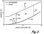
- FIG. 3 is a graph illustrating a cross-sectional profile of an exemplary optimized mid-turbine frame assembly 32 according to the present invention compared to another mid-turbine frame cross-sectional profile.
- a percentage of illustrated radial distance i.e., radial location %) is shown along the vertical axis, and a percentage of illustrated axial distance (i.e., axial location %) is shown along the horizontal axis.
- a base profile is shown with dashed lines representing inner diameter surface 56'.
- An exemplary optimized duct profile according to the present invention is shown with solid lines representing the inner and outer diameter surfaces 56 and 58, respectively.
- the cross-sectional profile can vary from that illustrated in FIG. 3 depending upon factors such as the shape and arrangement of the vanes 52, the shape of the HPT blades 40, and other engine design and operational factors.
Landscapes
- Engineering & Computer Science (AREA)
- Mechanical Engineering (AREA)
- General Engineering & Computer Science (AREA)
- Physics & Mathematics (AREA)
- Fluid Mechanics (AREA)
- Chemical & Material Sciences (AREA)
- Combustion & Propulsion (AREA)
- Turbine Rotor Nozzle Sealing (AREA)
- Structures Of Non-Positive Displacement Pumps (AREA)
Claims (5)
- Ensemble de conduit pour turbine moyenne pour un moteur à turbine à gaz, l'ensemble comprenant :un conduit (50) définissant une voie d'écoulement généralement annulaire, le conduit comprenant une région de conduit avant qui définit un rayon de voie d'écoulement annulaire croissant dans une direction en aval ;et caractérisé en ce que :le conduit comprend une région de conduit en aval située de manière adjacente à et vers l'arrière de la région de conduit avant, dans lequel la région de conduit en aval définit un renflement (64) s'étendant dans la voie d'écoulement généralement annulaire ; etl'ensemble comprend une vanne de cadre de turbine moyenne (52) positionnée sur la région de conduit en aval,dans lequel une arête avant (60) de la vanne de cadre de turbine moyenne est positionnée sur le renflement dans la région de conduit en aval.
- Ensemble selon la revendication 1, dans lequel le renflement comprend une surface de diamètre intérieur (56) renflée radialement vers l'extérieur.
- Ensemble selon la revendication 1 ou 2, dans lequel l'arête avant de la vanne de cadre de turbine moyenne est positionnée sur la région qui est radialement concave vers l'intérieur dans la région de conduit en aval.
- Ensemble selon la revendication 1, 2 ou 3, dans lequel une vitesse de changement d'une zone de voie d'écoulement dans le conduit diminue sur le renflement de la surface de diamètre intérieur.
- Ensemble de moteur à turbine à gaz (20) comprenant :une première section de turbine (30) ;une seconde section de turbine (34) située en aval de la première section de turbine ; etun ensemble de cadre de turbine moyenne (32) situé entre les première et seconde sections de turbine, l'ensemble de cadre de turbine moyenne comprenant un ensemble de conduit de turbine moyenne selon une quelconque revendication précédente.
Applications Claiming Priority (1)
| Application Number | Priority Date | Filing Date | Title |
|---|---|---|---|
| US12/228,947 US8061980B2 (en) | 2008-08-18 | 2008-08-18 | Separation-resistant inlet duct for mid-turbine frames |
Publications (3)
| Publication Number | Publication Date |
|---|---|
| EP2159398A2 EP2159398A2 (fr) | 2010-03-03 |
| EP2159398A3 EP2159398A3 (fr) | 2013-08-28 |
| EP2159398B1 true EP2159398B1 (fr) | 2017-04-26 |
Family
ID=41480069
Family Applications (1)
| Application Number | Title | Priority Date | Filing Date |
|---|---|---|---|
| EP09252017.0A Active EP2159398B1 (fr) | 2008-08-18 | 2009-08-18 | Conduite d'entrée résistante à la séparation pour cadres moyennes de turbines |
Country Status (2)
| Country | Link |
|---|---|
| US (1) | US8061980B2 (fr) |
| EP (1) | EP2159398B1 (fr) |
Cited By (1)
| Publication number | Priority date | Publication date | Assignee | Title |
|---|---|---|---|---|
| DE102021130997A1 (de) | 2021-11-25 | 2023-05-25 | MTU Aero Engines AG | Verdichtungssystem für eine Gasturbine, Hochdruckverdichter, Verdichtungssystem umfassend einen Hochdruckverdichter Niederdruckverdichter, Verdichtungssystem umfassend einen Niederdruckverdichter und Gasturbine |
Families Citing this family (27)
| Publication number | Priority date | Publication date | Assignee | Title |
|---|---|---|---|---|
| DE102008060847B4 (de) * | 2008-12-06 | 2020-03-19 | MTU Aero Engines AG | Strömungsmaschine |
| US20120275922A1 (en) * | 2011-04-26 | 2012-11-01 | Praisner Thomas J | High area ratio turbine vane |
| JP2012233406A (ja) * | 2011-04-28 | 2012-11-29 | Hitachi Ltd | ガスタービン静翼 |
| US8845286B2 (en) * | 2011-08-05 | 2014-09-30 | Honeywell International Inc. | Inter-turbine ducts with guide vanes |
| US20130219907A1 (en) * | 2012-02-29 | 2013-08-29 | Frederick M. Schwarz | Geared turbofan architecture for improved thrust density |
| EP2644846A1 (fr) * | 2012-03-30 | 2013-10-02 | Alstom Technology Ltd | Diffuseur d'échappement d'une turbine à gaz |
| US9074485B2 (en) * | 2012-04-25 | 2015-07-07 | United Technologies Corporation | Geared turbofan with three turbines all counter-rotating |
| US9534497B2 (en) * | 2012-05-02 | 2017-01-03 | Honeywell International Inc. | Inter-turbine ducts with variable area ratios |
| EP2669474B1 (fr) | 2012-06-01 | 2019-08-07 | MTU Aero Engines AG | Canal de passage pour une turbomachine et turbomachine |
| US9267386B2 (en) | 2012-06-29 | 2016-02-23 | United Technologies Corporation | Fairing assembly |
| US9587514B2 (en) * | 2012-07-13 | 2017-03-07 | United Technologies Corporation | Vane insertable tie rods with keyed connections |
| US9222413B2 (en) | 2012-07-13 | 2015-12-29 | United Technologies Corporation | Mid-turbine frame with threaded spokes |
| EP2885506B8 (fr) | 2012-08-17 | 2021-03-31 | Raytheon Technologies Corporation | Surface profilée de chemin d'écoulement |
| US9222437B2 (en) | 2012-09-21 | 2015-12-29 | General Electric Company | Transition duct for use in a turbine engine and method of assembly |
| US9617870B2 (en) | 2013-02-05 | 2017-04-11 | United Technologies Corporation | Bracket for mounting a stator guide vane arrangement to a strut in a turbine engine |
| EP2971521B1 (fr) | 2013-03-11 | 2022-06-22 | Rolls-Royce Corporation | Géométrie de voie d'écoulement de turbine à gaz |
| US9879540B2 (en) | 2013-03-12 | 2018-01-30 | Pratt & Whitney Canada Corp. | Compressor stator with contoured endwall |
| US9598981B2 (en) * | 2013-11-22 | 2017-03-21 | Siemens Energy, Inc. | Industrial gas turbine exhaust system diffuser inlet lip |
| WO2015105654A1 (fr) | 2014-01-08 | 2015-07-16 | United Technologies Corporation | Joint de serrage pour cadre de turbine intermédiaire de turboréacteur |
| WO2015156889A2 (fr) * | 2014-01-28 | 2015-10-15 | United Technologies Corporation | Aube fixe pour cadre dans partie intermédiaire de turbine d'un moteur à réaction |
| US20150240712A1 (en) * | 2014-02-24 | 2015-08-27 | United Technologies Corporation | Mid-turbine duct for geared gas turbine engine |
| US10344602B2 (en) * | 2016-04-18 | 2019-07-09 | General Electric Company | Gas turbine engine transition duct and turbine center frame |
| JP6449218B2 (ja) * | 2016-12-15 | 2019-01-09 | 三菱重工航空エンジン株式会社 | トランジションダクト、タービン、及びガスタービンエンジン |
| GB2558917B (en) * | 2017-01-19 | 2021-02-10 | Gkn Aerospace Sweden Ab | Transition duct of a multi-stage compressor with areas of different surface roughness |
| US10502076B2 (en) | 2017-11-09 | 2019-12-10 | Honeywell International Inc. | Inter-turbine ducts with flow control mechanisms |
| DE102018208151A1 (de) | 2018-05-24 | 2019-11-28 | MTU Aero Engines AG | Turbinenzwischengehäuse mit spezifisch ausgebildeter Ringraumkontur |
| US11242770B2 (en) | 2020-04-02 | 2022-02-08 | General Electric Company | Turbine center frame and method |
Family Cites Families (25)
| Publication number | Priority date | Publication date | Assignee | Title |
|---|---|---|---|---|
| US2735612A (en) * | 1956-02-21 | hausmann | ||
| US2594042A (en) * | 1947-05-21 | 1952-04-22 | United Aircraft Corp | Boundary layer energizing means for annular diffusers |
| US3704075A (en) * | 1970-12-14 | 1972-11-28 | Caterpillar Tractor Co | Combined turbine nozzle and bearing frame |
| BE791058A (fr) | 1971-11-08 | 1973-03-01 | Boeing Co | Moteurs a taux de derivation accru ou variable |
| US5758488A (en) * | 1993-05-11 | 1998-06-02 | Roderick Thomson | Core flow expansion chamber device system for reduction of jet turbine engine noise |
| DE19650656C1 (de) * | 1996-12-06 | 1998-06-10 | Mtu Muenchen Gmbh | Turbomaschine mit transsonischer Verdichterstufe |
| GB9823840D0 (en) * | 1998-10-30 | 1998-12-23 | Rolls Royce Plc | Bladed ducting for turbomachinery |
| US6488470B1 (en) * | 1999-08-03 | 2002-12-03 | Jerzy A. Owczarek | Annular flow diffusers for gas turbines |
| US6338609B1 (en) * | 2000-02-18 | 2002-01-15 | General Electric Company | Convex compressor casing |
| US6708482B2 (en) * | 2001-11-29 | 2004-03-23 | General Electric Company | Aircraft engine with inter-turbine engine frame |
| FR2835019B1 (fr) * | 2002-01-22 | 2004-12-31 | Snecma Moteurs | Diffuseur pour moteur a turbine a gaz terrestre ou aeronautique |
| US6732502B2 (en) * | 2002-03-01 | 2004-05-11 | General Electric Company | Counter rotating aircraft gas turbine engine with high overall pressure ratio compressor |
| US6619030B1 (en) * | 2002-03-01 | 2003-09-16 | General Electric Company | Aircraft engine with inter-turbine engine frame supported counter rotating low pressure turbine rotors |
| US6851264B2 (en) * | 2002-10-24 | 2005-02-08 | General Electric Company | Self-aspirating high-area-ratio inter-turbine duct assembly for use in a gas turbine engine |
| US6896475B2 (en) * | 2002-11-13 | 2005-05-24 | General Electric Company | Fluidic actuation for improved diffuser performance |
| US7137245B2 (en) * | 2004-06-18 | 2006-11-21 | General Electric Company | High area-ratio inter-turbine duct with inlet blowing |
| US7610179B2 (en) * | 2004-09-24 | 2009-10-27 | United Technologies Corporation | Coupled parametric design of flow control and duct shape |
| US7306436B2 (en) * | 2006-03-02 | 2007-12-11 | Pratt & Whitney Canada Corp. | HP turbine blade airfoil profile |
| US7677047B2 (en) * | 2006-03-29 | 2010-03-16 | United Technologies Corporation | Inverted stiffened shell panel torque transmission for loaded struts and mid-turbine frames |
| US7775049B2 (en) * | 2006-04-04 | 2010-08-17 | United Technologies Corporation | Integrated strut design for mid-turbine frames with U-base |
| US7610763B2 (en) * | 2006-05-09 | 2009-11-03 | United Technologies Corporation | Tailorable design configuration topologies for aircraft engine mid-turbine frames |
| US7594404B2 (en) * | 2006-07-27 | 2009-09-29 | United Technologies Corporation | Embedded mount for mid-turbine frame |
| US7870719B2 (en) * | 2006-10-13 | 2011-01-18 | General Electric Company | Plasma enhanced rapidly expanded gas turbine engine transition duct |
| US7762087B2 (en) * | 2006-12-06 | 2010-07-27 | United Technologies Corporation | Rotatable integrated segmented mid-turbine frames |
| US7762509B2 (en) * | 2007-10-18 | 2010-07-27 | United Technologies Corp. | Gas turbine engine systems involving rotatable annular supports |
-
2008
- 2008-08-18 US US12/228,947 patent/US8061980B2/en active Active
-
2009
- 2009-08-18 EP EP09252017.0A patent/EP2159398B1/fr active Active
Non-Patent Citations (1)
| Title |
|---|
| None * |
Cited By (1)
| Publication number | Priority date | Publication date | Assignee | Title |
|---|---|---|---|---|
| DE102021130997A1 (de) | 2021-11-25 | 2023-05-25 | MTU Aero Engines AG | Verdichtungssystem für eine Gasturbine, Hochdruckverdichter, Verdichtungssystem umfassend einen Hochdruckverdichter Niederdruckverdichter, Verdichtungssystem umfassend einen Niederdruckverdichter und Gasturbine |
Also Published As
| Publication number | Publication date |
|---|---|
| EP2159398A2 (fr) | 2010-03-03 |
| US8061980B2 (en) | 2011-11-22 |
| US20100040462A1 (en) | 2010-02-18 |
| EP2159398A3 (fr) | 2013-08-28 |
Similar Documents
| Publication | Publication Date | Title |
|---|---|---|
| EP2159398B1 (fr) | Conduite d'entrée résistante à la séparation pour cadres moyennes de turbines | |
| EP2935789B1 (fr) | Ensemble de surfaces portantes avec profilage de parois d'extrémité appariées | |
| EP2256299B1 (fr) | Déflecteur pour ensemble d'anneau d'aube de moteur de turbine à gaz | |
| US8007229B2 (en) | Variable area turbine vane arrangement | |
| US10458427B2 (en) | Compressor aerofoil | |
| EP3032033B1 (fr) | Ensemble de vanne pour moteur de turbine à gaz | |
| US9359900B2 (en) | Exhaust diffuser | |
| US20150204201A1 (en) | Contoured flowpath surface | |
| US20150147179A1 (en) | Blade with 3d platform comprising an inter-blade bulb | |
| US20170102004A1 (en) | Compressor aerofoil and corresponding compressor rotor assembly | |
| EP3701127B1 (fr) | Surface portante de compresseur | |
| US20140086739A1 (en) | Transition duct for use in a turbine engine and method of assembly | |
| EP3098383B1 (fr) | Aubage compresseur présentant un profil de bord d'attaque composé | |
| US20190264568A1 (en) | Guide vane airfoil for the hot gas flow path of a turbomachine | |
| WO2010002294A1 (fr) | Aube pour composant de turbine à gaz, composant de turbine à gaz et turbine à gaz | |
| US11933193B2 (en) | Turbine engine with an airfoil having a set of dimples | |
| US9140136B2 (en) | Stress-relieved wire seal assembly for gas turbine engines | |
| US11608746B2 (en) | Airfoils for gas turbine engines | |
| US9500084B2 (en) | Impeller | |
| US11280204B2 (en) | Air flow straightening assembly and turbomachine including such an assembly | |
| US10738638B2 (en) | Rotor blade with wheel space swirlers and method for forming a rotor blade with wheel space swirlers | |
| US10570743B2 (en) | Turbomachine having an annulus enlargment and airfoil | |
| US11939880B1 (en) | Airfoil assembly with flow surface | |
| JP7273363B2 (ja) | 軸流圧縮機 |
Legal Events
| Date | Code | Title | Description |
|---|---|---|---|
| PUAI | Public reference made under article 153(3) epc to a published international application that has entered the european phase |
Free format text: ORIGINAL CODE: 0009012 |
|
| AK | Designated contracting states |
Kind code of ref document: A2 Designated state(s): AT BE BG CH CY CZ DE DK EE ES FI FR GB GR HR HU IE IS IT LI LT LU LV MC MK MT NL NO PL PT RO SE SI SK SM TR |
|
| AX | Request for extension of the european patent |
Extension state: AL BA RS |
|
| PUAL | Search report despatched |
Free format text: ORIGINAL CODE: 0009013 |
|
| AK | Designated contracting states |
Kind code of ref document: A3 Designated state(s): AT BE BG CH CY CZ DE DK EE ES FI FR GB GR HR HU IE IS IT LI LT LU LV MC MK MT NL NO PL PT RO SE SI SK SM TR |
|
| AX | Request for extension of the european patent |
Extension state: AL BA RS |
|
| RIC1 | Information provided on ipc code assigned before grant |
Ipc: F01D 9/04 20060101ALI20130719BHEP Ipc: F01D 9/02 20060101ALI20130719BHEP Ipc: F01D 5/14 20060101ALI20130719BHEP Ipc: F02C 7/20 20060101AFI20130719BHEP Ipc: F01D 25/30 20060101ALI20130719BHEP |
|
| 17P | Request for examination filed |
Effective date: 20140228 |
|
| RBV | Designated contracting states (corrected) |
Designated state(s): AT BE BG CH CY CZ DE DK EE ES FI FR GB GR HR HU IE IS IT LI LT LU LV MC MK MT NL NO PL PT RO SE SI SK SM TR |
|
| RAP1 | Party data changed (applicant data changed or rights of an application transferred) |
Owner name: UNITED TECHNOLOGIES CORPORATION |
|
| GRAP | Despatch of communication of intention to grant a patent |
Free format text: ORIGINAL CODE: EPIDOSNIGR1 |
|
| INTG | Intention to grant announced |
Effective date: 20161221 |
|
| GRAS | Grant fee paid |
Free format text: ORIGINAL CODE: EPIDOSNIGR3 |
|
| GRAA | (expected) grant |
Free format text: ORIGINAL CODE: 0009210 |
|
| AK | Designated contracting states |
Kind code of ref document: B1 Designated state(s): AT BE BG CH CY CZ DE DK EE ES FI FR GB GR HR HU IE IS IT LI LT LU LV MC MK MT NL NO PL PT RO SE SI SK SM TR |
|
| REG | Reference to a national code |
Ref country code: GB Ref legal event code: FG4D |
|
| REG | Reference to a national code |
Ref country code: CH Ref legal event code: EP |
|
| REG | Reference to a national code |
Ref country code: AT Ref legal event code: REF Ref document number: 888106 Country of ref document: AT Kind code of ref document: T Effective date: 20170515 |
|
| REG | Reference to a national code |
Ref country code: IE Ref legal event code: FG4D |
|
| REG | Reference to a national code |
Ref country code: DE Ref legal event code: R096 Ref document number: 602009045668 Country of ref document: DE |
|
| REG | Reference to a national code |
Ref country code: DE Ref legal event code: R082 Ref document number: 602009045668 Country of ref document: DE Representative=s name: SCHMITT-NILSON SCHRAUD WAIBEL WOHLFROM PATENTA, DE |
|
| REG | Reference to a national code |
Ref country code: FR Ref legal event code: PLFP Year of fee payment: 9 |
|
| REG | Reference to a national code |
Ref country code: NL Ref legal event code: MP Effective date: 20170426 |
|
| REG | Reference to a national code |
Ref country code: LT Ref legal event code: MG4D |
|
| REG | Reference to a national code |
Ref country code: AT Ref legal event code: MK05 Ref document number: 888106 Country of ref document: AT Kind code of ref document: T Effective date: 20170426 |
|
| PG25 | Lapsed in a contracting state [announced via postgrant information from national office to epo] |
Ref country code: NL Free format text: LAPSE BECAUSE OF FAILURE TO SUBMIT A TRANSLATION OF THE DESCRIPTION OR TO PAY THE FEE WITHIN THE PRESCRIBED TIME-LIMIT Effective date: 20170426 |
|
| PG25 | Lapsed in a contracting state [announced via postgrant information from national office to epo] |
Ref country code: HR Free format text: LAPSE BECAUSE OF FAILURE TO SUBMIT A TRANSLATION OF THE DESCRIPTION OR TO PAY THE FEE WITHIN THE PRESCRIBED TIME-LIMIT Effective date: 20170426 Ref country code: FI Free format text: LAPSE BECAUSE OF FAILURE TO SUBMIT A TRANSLATION OF THE DESCRIPTION OR TO PAY THE FEE WITHIN THE PRESCRIBED TIME-LIMIT Effective date: 20170426 Ref country code: AT Free format text: LAPSE BECAUSE OF FAILURE TO SUBMIT A TRANSLATION OF THE DESCRIPTION OR TO PAY THE FEE WITHIN THE PRESCRIBED TIME-LIMIT Effective date: 20170426 Ref country code: LT Free format text: LAPSE BECAUSE OF FAILURE TO SUBMIT A TRANSLATION OF THE DESCRIPTION OR TO PAY THE FEE WITHIN THE PRESCRIBED TIME-LIMIT Effective date: 20170426 Ref country code: ES Free format text: LAPSE BECAUSE OF FAILURE TO SUBMIT A TRANSLATION OF THE DESCRIPTION OR TO PAY THE FEE WITHIN THE PRESCRIBED TIME-LIMIT Effective date: 20170426 Ref country code: GR Free format text: LAPSE BECAUSE OF FAILURE TO SUBMIT A TRANSLATION OF THE DESCRIPTION OR TO PAY THE FEE WITHIN THE PRESCRIBED TIME-LIMIT Effective date: 20170727 Ref country code: NO Free format text: LAPSE BECAUSE OF FAILURE TO SUBMIT A TRANSLATION OF THE DESCRIPTION OR TO PAY THE FEE WITHIN THE PRESCRIBED TIME-LIMIT Effective date: 20170726 |
|
| PG25 | Lapsed in a contracting state [announced via postgrant information from national office to epo] |
Ref country code: PL Free format text: LAPSE BECAUSE OF FAILURE TO SUBMIT A TRANSLATION OF THE DESCRIPTION OR TO PAY THE FEE WITHIN THE PRESCRIBED TIME-LIMIT Effective date: 20170426 Ref country code: BG Free format text: LAPSE BECAUSE OF FAILURE TO SUBMIT A TRANSLATION OF THE DESCRIPTION OR TO PAY THE FEE WITHIN THE PRESCRIBED TIME-LIMIT Effective date: 20170726 Ref country code: IS Free format text: LAPSE BECAUSE OF FAILURE TO SUBMIT A TRANSLATION OF THE DESCRIPTION OR TO PAY THE FEE WITHIN THE PRESCRIBED TIME-LIMIT Effective date: 20170826 Ref country code: SE Free format text: LAPSE BECAUSE OF FAILURE TO SUBMIT A TRANSLATION OF THE DESCRIPTION OR TO PAY THE FEE WITHIN THE PRESCRIBED TIME-LIMIT Effective date: 20170426 Ref country code: LV Free format text: LAPSE BECAUSE OF FAILURE TO SUBMIT A TRANSLATION OF THE DESCRIPTION OR TO PAY THE FEE WITHIN THE PRESCRIBED TIME-LIMIT Effective date: 20170426 |
|
| REG | Reference to a national code |
Ref country code: DE Ref legal event code: R097 Ref document number: 602009045668 Country of ref document: DE |
|
| PG25 | Lapsed in a contracting state [announced via postgrant information from national office to epo] |
Ref country code: SK Free format text: LAPSE BECAUSE OF FAILURE TO SUBMIT A TRANSLATION OF THE DESCRIPTION OR TO PAY THE FEE WITHIN THE PRESCRIBED TIME-LIMIT Effective date: 20170426 Ref country code: CZ Free format text: LAPSE BECAUSE OF FAILURE TO SUBMIT A TRANSLATION OF THE DESCRIPTION OR TO PAY THE FEE WITHIN THE PRESCRIBED TIME-LIMIT Effective date: 20170426 Ref country code: RO Free format text: LAPSE BECAUSE OF FAILURE TO SUBMIT A TRANSLATION OF THE DESCRIPTION OR TO PAY THE FEE WITHIN THE PRESCRIBED TIME-LIMIT Effective date: 20170426 Ref country code: EE Free format text: LAPSE BECAUSE OF FAILURE TO SUBMIT A TRANSLATION OF THE DESCRIPTION OR TO PAY THE FEE WITHIN THE PRESCRIBED TIME-LIMIT Effective date: 20170426 Ref country code: DK Free format text: LAPSE BECAUSE OF FAILURE TO SUBMIT A TRANSLATION OF THE DESCRIPTION OR TO PAY THE FEE WITHIN THE PRESCRIBED TIME-LIMIT Effective date: 20170426 |
|
| PG25 | Lapsed in a contracting state [announced via postgrant information from national office to epo] |
Ref country code: IT Free format text: LAPSE BECAUSE OF FAILURE TO SUBMIT A TRANSLATION OF THE DESCRIPTION OR TO PAY THE FEE WITHIN THE PRESCRIBED TIME-LIMIT Effective date: 20170426 Ref country code: SM Free format text: LAPSE BECAUSE OF FAILURE TO SUBMIT A TRANSLATION OF THE DESCRIPTION OR TO PAY THE FEE WITHIN THE PRESCRIBED TIME-LIMIT Effective date: 20170426 |
|
| PLBE | No opposition filed within time limit |
Free format text: ORIGINAL CODE: 0009261 |
|
| STAA | Information on the status of an ep patent application or granted ep patent |
Free format text: STATUS: NO OPPOSITION FILED WITHIN TIME LIMIT |
|
| REG | Reference to a national code |
Ref country code: CH Ref legal event code: PL |
|
| PG25 | Lapsed in a contracting state [announced via postgrant information from national office to epo] |
Ref country code: MC Free format text: LAPSE BECAUSE OF FAILURE TO SUBMIT A TRANSLATION OF THE DESCRIPTION OR TO PAY THE FEE WITHIN THE PRESCRIBED TIME-LIMIT Effective date: 20170426 |
|
| 26N | No opposition filed |
Effective date: 20180129 |
|
| PG25 | Lapsed in a contracting state [announced via postgrant information from national office to epo] |
Ref country code: CH Free format text: LAPSE BECAUSE OF NON-PAYMENT OF DUE FEES Effective date: 20170831 Ref country code: LI Free format text: LAPSE BECAUSE OF NON-PAYMENT OF DUE FEES Effective date: 20170831 |
|
| REG | Reference to a national code |
Ref country code: BE Ref legal event code: MM Effective date: 20170831 |
|
| REG | Reference to a national code |
Ref country code: IE Ref legal event code: MM4A |
|
| PG25 | Lapsed in a contracting state [announced via postgrant information from national office to epo] |
Ref country code: SI Free format text: LAPSE BECAUSE OF FAILURE TO SUBMIT A TRANSLATION OF THE DESCRIPTION OR TO PAY THE FEE WITHIN THE PRESCRIBED TIME-LIMIT Effective date: 20170426 |
|
| PG25 | Lapsed in a contracting state [announced via postgrant information from national office to epo] |
Ref country code: LU Free format text: LAPSE BECAUSE OF NON-PAYMENT OF DUE FEES Effective date: 20170818 |
|
| REG | Reference to a national code |
Ref country code: FR Ref legal event code: PLFP Year of fee payment: 10 |
|
| PG25 | Lapsed in a contracting state [announced via postgrant information from national office to epo] |
Ref country code: IE Free format text: LAPSE BECAUSE OF NON-PAYMENT OF DUE FEES Effective date: 20170818 |
|
| PG25 | Lapsed in a contracting state [announced via postgrant information from national office to epo] |
Ref country code: BE Free format text: LAPSE BECAUSE OF NON-PAYMENT OF DUE FEES Effective date: 20170831 |
|
| PG25 | Lapsed in a contracting state [announced via postgrant information from national office to epo] |
Ref country code: MT Free format text: LAPSE BECAUSE OF NON-PAYMENT OF DUE FEES Effective date: 20170818 |
|
| PG25 | Lapsed in a contracting state [announced via postgrant information from national office to epo] |
Ref country code: HU Free format text: LAPSE BECAUSE OF FAILURE TO SUBMIT A TRANSLATION OF THE DESCRIPTION OR TO PAY THE FEE WITHIN THE PRESCRIBED TIME-LIMIT; INVALID AB INITIO Effective date: 20090818 |
|
| PG25 | Lapsed in a contracting state [announced via postgrant information from national office to epo] |
Ref country code: CY Free format text: LAPSE BECAUSE OF NON-PAYMENT OF DUE FEES Effective date: 20170426 |
|
| PG25 | Lapsed in a contracting state [announced via postgrant information from national office to epo] |
Ref country code: MK Free format text: LAPSE BECAUSE OF FAILURE TO SUBMIT A TRANSLATION OF THE DESCRIPTION OR TO PAY THE FEE WITHIN THE PRESCRIBED TIME-LIMIT Effective date: 20170426 |
|
| PG25 | Lapsed in a contracting state [announced via postgrant information from national office to epo] |
Ref country code: TR Free format text: LAPSE BECAUSE OF FAILURE TO SUBMIT A TRANSLATION OF THE DESCRIPTION OR TO PAY THE FEE WITHIN THE PRESCRIBED TIME-LIMIT Effective date: 20170426 |
|
| PG25 | Lapsed in a contracting state [announced via postgrant information from national office to epo] |
Ref country code: PT Free format text: LAPSE BECAUSE OF FAILURE TO SUBMIT A TRANSLATION OF THE DESCRIPTION OR TO PAY THE FEE WITHIN THE PRESCRIBED TIME-LIMIT Effective date: 20170426 |
|
| REG | Reference to a national code |
Ref country code: DE Ref legal event code: R081 Ref document number: 602009045668 Country of ref document: DE Owner name: RAYTHEON TECHNOLOGIES CORPORATION (N.D.GES.D.S, US Free format text: FORMER OWNER: UNITED TECHNOLOGIES CORPORATION, FARMINGTON, CONN., US |
|
| P01 | Opt-out of the competence of the unified patent court (upc) registered |
Effective date: 20230519 |
|
| PGFP | Annual fee paid to national office [announced via postgrant information from national office to epo] |
Ref country code: GB Payment date: 20230720 Year of fee payment: 15 |
|
| PGFP | Annual fee paid to national office [announced via postgrant information from national office to epo] |
Ref country code: FR Payment date: 20230720 Year of fee payment: 15 Ref country code: DE Payment date: 20230720 Year of fee payment: 15 |