EP2159372B1 - Fixture for compressor stator chord restoration repair - Google Patents
Fixture for compressor stator chord restoration repair Download PDFInfo
- Publication number
- EP2159372B1 EP2159372B1 EP09251500.6A EP09251500A EP2159372B1 EP 2159372 B1 EP2159372 B1 EP 2159372B1 EP 09251500 A EP09251500 A EP 09251500A EP 2159372 B1 EP2159372 B1 EP 2159372B1
- Authority
- EP
- European Patent Office
- Prior art keywords
- workpiece
- feet
- airfoil
- engagement
- mounting block
- Prior art date
- Legal status (The legal status is an assumption and is not a legal conclusion. Google has not performed a legal analysis and makes no representation as to the accuracy of the status listed.)
- Active
Links
- 230000008439 repair process Effects 0.000 title description 11
- 238000000034 method Methods 0.000 claims description 15
- 230000014759 maintenance of location Effects 0.000 claims description 4
- 230000000881 depressing effect Effects 0.000 claims 1
- 239000000463 material Substances 0.000 description 19
- 239000000945 filler Substances 0.000 description 13
- 238000000429 assembly Methods 0.000 description 4
- 230000000712 assembly Effects 0.000 description 4
- 238000005242 forging Methods 0.000 description 2
- 238000005219 brazing Methods 0.000 description 1
- 230000002401 inhibitory effect Effects 0.000 description 1
- 238000002955 isolation Methods 0.000 description 1
- 238000005304 joining Methods 0.000 description 1
- 238000003466 welding Methods 0.000 description 1
Images


Classifications
-
- F—MECHANICAL ENGINEERING; LIGHTING; HEATING; WEAPONS; BLASTING
- F01—MACHINES OR ENGINES IN GENERAL; ENGINE PLANTS IN GENERAL; STEAM ENGINES
- F01D—NON-POSITIVE DISPLACEMENT MACHINES OR ENGINES, e.g. STEAM TURBINES
- F01D5/00—Blades; Blade-carrying members; Heating, heat-insulating, cooling or antivibration means on the blades or the members
- F01D5/005—Repairing methods or devices
-
- B—PERFORMING OPERATIONS; TRANSPORTING
- B23—MACHINE TOOLS; METAL-WORKING NOT OTHERWISE PROVIDED FOR
- B23P—METAL-WORKING NOT OTHERWISE PROVIDED FOR; COMBINED OPERATIONS; UNIVERSAL MACHINE TOOLS
- B23P6/00—Restoring or reconditioning objects
- B23P6/002—Repairing turbine components, e.g. moving or stationary blades, rotors
-
- B—PERFORMING OPERATIONS; TRANSPORTING
- B23—MACHINE TOOLS; METAL-WORKING NOT OTHERWISE PROVIDED FOR
- B23Q—DETAILS, COMPONENTS, OR ACCESSORIES FOR MACHINE TOOLS, e.g. ARRANGEMENTS FOR COPYING OR CONTROLLING; MACHINE TOOLS IN GENERAL CHARACTERISED BY THE CONSTRUCTION OF PARTICULAR DETAILS OR COMPONENTS; COMBINATIONS OR ASSOCIATIONS OF METAL-WORKING MACHINES, NOT DIRECTED TO A PARTICULAR RESULT
- B23Q3/00—Devices holding, supporting, or positioning work or tools, of a kind normally removable from the machine
- B23Q3/02—Devices holding, supporting, or positioning work or tools, of a kind normally removable from the machine for mounting on a work-table, tool-slide, or analogous part
- B23Q3/06—Work-clamping means
- B23Q3/062—Work-clamping means adapted for holding workpieces having a special form or being made from a special material
- B23Q3/063—Work-clamping means adapted for holding workpieces having a special form or being made from a special material for holding turbine blades
-
- B—PERFORMING OPERATIONS; TRANSPORTING
- B25—HAND TOOLS; PORTABLE POWER-DRIVEN TOOLS; MANIPULATORS
- B25B—TOOLS OR BENCH DEVICES NOT OTHERWISE PROVIDED FOR, FOR FASTENING, CONNECTING, DISENGAGING OR HOLDING
- B25B5/00—Clamps
- B25B5/14—Clamps for work of special profile
-
- F—MECHANICAL ENGINEERING; LIGHTING; HEATING; WEAPONS; BLASTING
- F01—MACHINES OR ENGINES IN GENERAL; ENGINE PLANTS IN GENERAL; STEAM ENGINES
- F01D—NON-POSITIVE DISPLACEMENT MACHINES OR ENGINES, e.g. STEAM TURBINES
- F01D25/00—Component parts, details, or accessories, not provided for in, or of interest apart from, other groups
- F01D25/28—Supporting or mounting arrangements, e.g. for turbine casing
- F01D25/285—Temporary support structures, e.g. for testing, assembling, installing, repairing; Assembly methods using such structures
-
- F—MECHANICAL ENGINEERING; LIGHTING; HEATING; WEAPONS; BLASTING
- F05—INDEXING SCHEMES RELATING TO ENGINES OR PUMPS IN VARIOUS SUBCLASSES OF CLASSES F01-F04
- F05D—INDEXING SCHEME FOR ASPECTS RELATING TO NON-POSITIVE-DISPLACEMENT MACHINES OR ENGINES, GAS-TURBINES OR JET-PROPULSION PLANTS
- F05D2230/00—Manufacture
- F05D2230/80—Repairing, retrofitting or upgrading methods
-
- Y—GENERAL TAGGING OF NEW TECHNOLOGICAL DEVELOPMENTS; GENERAL TAGGING OF CROSS-SECTIONAL TECHNOLOGIES SPANNING OVER SEVERAL SECTIONS OF THE IPC; TECHNICAL SUBJECTS COVERED BY FORMER USPC CROSS-REFERENCE ART COLLECTIONS [XRACs] AND DIGESTS
- Y10—TECHNICAL SUBJECTS COVERED BY FORMER USPC
- Y10T—TECHNICAL SUBJECTS COVERED BY FORMER US CLASSIFICATION
- Y10T29/00—Metal working
- Y10T29/49—Method of mechanical manufacture
- Y10T29/49998—Work holding
-
- Y—GENERAL TAGGING OF NEW TECHNOLOGICAL DEVELOPMENTS; GENERAL TAGGING OF CROSS-SECTIONAL TECHNOLOGIES SPANNING OVER SEVERAL SECTIONS OF THE IPC; TECHNICAL SUBJECTS COVERED BY FORMER USPC CROSS-REFERENCE ART COLLECTIONS [XRACs] AND DIGESTS
- Y10—TECHNICAL SUBJECTS COVERED BY FORMER USPC
- Y10T—TECHNICAL SUBJECTS COVERED BY FORMER US CLASSIFICATION
- Y10T29/00—Metal working
- Y10T29/53—Means to assemble or disassemble
- Y10T29/53961—Means to assemble or disassemble with work-holder for assembly
Definitions
- the present invention relates to fixtures and methods for holding workpieces, and more particularly to fixtures and methods for holding airfoil workpieces during coining operations of a repair process.
- Airfoils for gas turbine engines can become worn or damaged during use, particularly at leading and/or trailing edges.
- Replacement parts can be used to replace the damaged or worn airfoils to keep an engine in service, but replacement parts are often expensive. Repairing damaged or worn airfoils can be a more cost-effective approach.
- US 2005/0191177 A1 discloses a mounting block for an airfoil workpiece which secures the workpiece during repair.
- a fixture assembly for retaining a workpiece during a coining process includes a mounting block.
- the workpiece includes an airfoil portion, a platform, and feet extending from the platform opposite the airfoil portion and configured to engage a retention slot in a gas turbine engine, each foot defining a substantially arcuate engagement surface.
- the mounting block includes a first portion having a slot defined therein between opposite first and second lateral edges and having an exposed front face, first and second retaining structures positioned adjacent to the first and second lateral edges, respectively. Each of the first and second retaining structures overhangs the slot and defines an engagement surface facing the slot, such that during engagement of the workpiece the substantially arcuate engagement surfaces of the feet contact the engagement surfaces of the first and second retaining structures to provide a pivotable engagement.
- the exemplary embodiments provide fixture assemblies and methods for securing an airfoil workpiece during a coining (or forging or stamping) operation.
- the coining operation can be a part of a repair process performed on a worn or damaged airfoil.
- the fixture assembly and method are particularly suited to securing airfoils, such as compressor stators (or vanes), that include an airfoil portion, a platform adjacent to the airfoil portion, and feet located adjacent to the platform opposite the airfoil portion, where each of the feet defines an arcuate engagement surface.
- the exemplary fixture assembly provides means for retaining the airfoil workpiece during coining repair.
- the fixture assembly can include a biasing member, such as a spring-loaded pin, for biasing the airfoil workpiece to maintain engagement with the fixture assembly during coining, with movement or deflection of the biasing member allowing easy engagement and disengagement. This helps reduce the time and effort required to both engage and disengage the airfoil workpiece from the fixture assembly.
- the fixture assembly can secure the airfoil workpiece relative to a number of workpiece datums while still permitting pivotal movement of the airfoil workpiece during coining. Pivotal movement of the airfoil workpiece in the coining die can help alleviate undesired stress and deformation during the coining operation.
- FIG. 1 is a side view of an exemplary airfoil 20, and FIG. 2 is a front view of the airfoil 20.
- the airfoil 20 is a compressor stator for a gas turbine engine.
- the airfoil 20 includes an aerodynamically shaped airfoil portion 22, a platform 24 located adjacent to and joined with the airfoil portion 22, and first and second feet 26 and 28, respectively, extending from the platform 24 opposite the airfoil portion 22.
- the airfoil portion 22 defines a leading edge 30 and a trailing edge 32. As shown in FIGS.
- parent material of the airfoil portion 22 of the airfoil 20 has been removed along both the leading and trailing edges 30 and 32 and replaced with a filler material 34.
- the filler material 34 can be utilized to replace worn or damaged regions of the airfoil 20, and can be joined to the remaining parent material through known welding or brazing techniques.
- the filler material 34 can have substantially the same composition as the parent material.
- the filler material 34 is typically applied beyond an operational condition edge location of the airfoil 20, that is, the filler material 34 is applied to a thickness greater than that of the parent material removed, thereby providing excess filler material beyond the original blueprint specifications.
- the excess of the filler material 34 can be provided for a subsequent coining operation, which typically reduces the amount of excess filler material beyond the original blueprint specifications.
- the feet 26 and 28 are configured to engage the airfoil 20 within a gas turbine engine.
- the feet 26 and 28 are configured to secure the airfoil 20 to a circumferential slot in the engine, with the airfoil portion 22 positioned radially inward of the feet 26 and 28.
- the feet 26 and 28 and the platform 24 are arcuate in shape (only foot 28 is visible in FIG. 2 ).
- the airfoil 20 in the illustrated embodiment defines at least three datums A, B and C.
- Datum A is defined at a radially outer surface of the feet 26 and 28, tangent to a midpoint of that arcuate surface.
- Datum B is defined at a lateral surface of the platform 24 and the feet 26 and 28.
- Datum C is located at a forward edge of the platform 24 and an adjacent, radially-extending portion of the foot 28.
- the illustrated datums are provided by way of example and not limitation, and in alternative embodiments the datums A, B and C can be defined in other locations on the airfoil 20.
- airfoil 20 is merely an exemplary embodiment, and a variety of other airfoil configurations are possible. Also, the exemplary fixture assemblies and methods discussed below are not limited to use with airfoils having the particular configuration of the airfoil 20 as illustrated.
- FIG. 3 is a perspective view of a first embodiment of a fixture assembly 40 that includes a base 42, a mounting block 44 attached to the base 42, and a portion of a coining (or forging) die 46 attached to the base 42 adjacent to the mounting block 44.
- FIG. 4 is a side view of the airfoil 20 engaged to the mounting block 44 of the fixture assembly 40.
- the mounting block 44 is shown in isolation, separate from the rest of the fixture assembly 40.
- the mounting block 44 includes a base portion 48 having openings 50 therein for accepting fasteners (e.g., bolts) for securing the mounting block 44 to the base 42 (see FIG. 1 ).
- First and second lateral portions 52 and 54 extend outward from the base portion 48, with a slot S defined in the mounting block 44 between the first and second lateral portions 52 and 54.
- the base portion 48 and the first and second lateral portions 52 and 54 of the mounting block 44 define edges of the slot S.
- the slot S is substantially open at three faces.
- First and second retaining structures 56 and 58 extend from the first and second lateral portions 52 and 54, respectively.
- the first and second retaining structures 56 and 58 each overhang the slot S and define an engagement surface facing the slot S.
- the engagement surfaces of the first and second retaining structures 56 and 58 are each substantially planar.
- the engagement surfaces of the first and second retaining structures 56 and 58 can be arranged substantially parallel to each other.
- a retaining pin 60 is provided that extends from the base portion 48 of the mounting block 44 into the slot S, opposite the engagement surfaces of the first and second retaining structures 56 and 58.
- the retaining pin 60 is substantially cylindrical in shape in the illustrated embodiment, but can have other shapes in alternative embodiments, for instance, having a rounded or pointed distal end for contacting workpieces.
- the retaining pin 60 can be spring-loaded, or biased with other suitable means, to provide a biasing force in a direction toward the engagement surfaces of the first and second retaining structures 56 and 58.
- the retaining pin 60 can contact the platform 24 to bias the airfoil 20 against the engagement surfaces of the first and second retaining structures 56 and 58, for instance, in order to maintain engagement with the fixture assembly during coining.
- the retaining pin 60 allows the airfoil 20 to be engaged and disengaged from the fixture assembly 40 relatively quickly, and typically much more quickly compared to known fixture assemblies that include threaded fasteners or clamping structures for holding the airfoil 20 to the fixture assembly 40. Depression of the retaining pin 60 saves time compared to torquing retaining fasteners or operating many types of clamping structures such that the fixture assembly 20 facilitates reducing the overall time and expense associated with airfoil coining repairs.
- the airfoil 20 is engaged with the mounting block 44 in such a way that substantially arcuate engagement surfaces of the first and second feet 26 and 28, which face the platform 24, contact the engagement surfaces of the first and second retaining structures 56 and 58, respectively, to provide a pivotable engagement.
- This pivotable engagement helps keep the fixture assembly 40 closely aligned relative to the datums A and C of the airfoil 20.
- FIG. 5 is a perspective view of the airfoil 20 engaged with the fixture assembly 40.
- the airfoil portion 22 is arranged in a substantially horizontal orientation and is positioned against the portion of the coining die 46.
- the feet 26 and 28 are engaged to the mounting block 44, which is positioned at a non-horizontal angle with respect to the base 42. Positioning the mounting block 44 at an angle allows the airfoil portion 22 of the engaged airfoil 20 to lie substantially horizontally along the die 46.
- a pivot axis 62 is defined about which the airfoil 20 can pivot during a coining operation, where another die portion (not shown) comes together with the die 46 to apply force to the airfoil portion 22 located therebetween.
- the pivot axis 62 is defined between points located generally at opposite corners of the substantially arcuate engagement surfaces of the first and second feet 26 and 28, where those first and second feet 26 and 28 contact the engagement surfaces of the first and second retaining structures 56 and 58. In this embodiment, the pivot axis 62 is arranged substantially horizontally.
- coining dies can exert many tons of force on airfoils that often include relatively thin regions
- coining operations can produce stress and potentially deform the airfoil 20 in an undesired manner (e.g., twisting the airfoil portion 22 out of conformity with an original blueprint configuration or beyond engine manual serviceable limits).
- Configuration of the fixture assembly 40 to allow pivotal movement of the airfoil 20 about the pivot axis 62 during coining operations can help alleviate such undesired stress and deformation, while still focusing force of the coining dies in a desired manner.
- the slot S in the mounting block 44 provides enough space for the first and second feet 26 and 28 to move freely as the airfoil 20 pivots about the pivot axis 62.
- Datums of the airfoil 20 can thereby remain closely aligned relative to the fixture assembly 40 to provide relatively precise and accurate coining, while still allowing pivotal movement.
- the biased retaining pin 60 helps the airfoil 20 remain engaged with the fixture assembly 40 during coining, but without inhibiting pivotal movement of the airfoil 20 about the pivot axis 62.
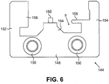
- FIG. 6 is a top view of a second embodiment of a mounting block 144 for the fixture assembly 40.
- the configuration of the mounting block 144, with a base portion 148, openings 150 and first and second lateral portions 152 and 154, is generally similar to those described above with respect to the mounting block 44, with similar subcomponents designated in FIG. 6 by similar reference numbers with numerical values increased by one hundred.
- the mounting block 144 further includes a protrusion 164 extending from the base portion 148 in which the biased retaining pin 160 extends.
- the first and second retaining structures 156 and 158 are also positioned relatively close to the base portion 148.
- engagement surfaces of the first and second retaining structures 156 and 158 can be planar or arcuate.
- the second retaining structure 158 can have a cylindrical shape, with a pivot axis arranged coaxially with the cylindrical second retaining structure 158. Furthermore, the second lateral portion 154 can extend past the second retaining structure 158, such that second retaining structure 158 is positioned within the slot S.
- FIG. 7 is a side view of the airfoil 20 (having first and second feet 26 and 28) engaged with a third embodiment of a mounting block 244, and FIG. 8 is a front view of the airfoil 20 engaged with the mounting block 244.
- the configuration of the mounting block 244, having a base portion 248 with first and second lateral portions 252 and 254 extending therefrom, is generally similar to those described above with respect to the mounting block 144, with similar subcomponents designated in FIGS. 7 and 8 by similar reference numbers with numerical values increased by one hundred.
- the mounting block 244 omits the retaining pin, and the first and second retaining structures 256 and 258 are both formed as cylinders. As shown in FIG.
- a distal end of the second retaining structure 258 abuts the datum C of the airfoil 20.
- the second retaining structure 258 contacts a middle portion of the second foot 28 of the airfoil 20.
- the base portion 248 forms an additional mounting surface that is substantially planar and contacts both the first and second feet 26 and 28.
- fixture assembly can vary to accommodate particular airfoil workpieces desired to be engaged thereto.
Description
- The present invention relates to fixtures and methods for holding workpieces, and more particularly to fixtures and methods for holding airfoil workpieces during coining operations of a repair process.
- Airfoils for gas turbine engines, such as compressor stators (or vanes), can become worn or damaged during use, particularly at leading and/or trailing edges. Replacement parts can be used to replace the damaged or worn airfoils to keep an engine in service, but replacement parts are often expensive. Repairing damaged or worn airfoils can be a more cost-effective approach.
- Known repairs of airfoil edges can involve removing material at the location of wear or damage, then joining a filler material that is then machined to original blueprint dimensions. With repairs that include coining operations, filler material added to the airfoil workpiece during repair can cause coining dies to exert relatively uneven force patterns, which can produce stress and potentially deform the airfoil workpiece in an undesired manner (e.g., twisting the airfoil portion out of conformity with an original blueprint configuration or beyond engine manual serviceable limits).
-
US 2005/0191177 A1 discloses a mounting block for an airfoil workpiece which secures the workpiece during repair. - A fixture assembly for retaining a workpiece during a coining process includes a mounting block. The workpiece includes an airfoil portion, a platform, and feet extending from the platform opposite the airfoil portion and configured to engage a retention slot in a gas turbine engine, each foot defining a substantially arcuate engagement surface. The mounting block includes a first portion having a slot defined therein between opposite first and second lateral edges and having an exposed front face, first and second retaining structures positioned adjacent to the first and second lateral edges, respectively. Each of the first and second retaining structures overhangs the slot and defines an engagement surface facing the slot, such that during engagement of the workpiece the substantially arcuate engagement surfaces of the feet contact the engagement surfaces of the first and second retaining structures to provide a pivotable engagement.
-
-
FIG. 1 is a side view of an exemplary airfoil. -
FIG. 2 is a front view of the airfoil ofFIG. 1 . -
FIG. 3 is a perspective view of a first embodiment of a fixture assembly according to the present invention. -
FIG. 4 is a side view of the airfoil engaged to a mounting block of the first embodiment of the fixture assembly. -
FIG. 5 is a perspective view of the airfoil engaged with the first embodiment of the fixture assembly. -
FIG. 6 is a top view of a mounting block of a second embodiment of the fixture assembly. -
FIG. 7 is a side view of an airfoil engaged with a third embodiment of the fixture assembly according the present invention. -
FIG. 8 is a front view of the airfoil engaged with the third embodiment of the fixture assembly. - In general, the exemplary embodiments provide fixture assemblies and methods for securing an airfoil workpiece during a coining (or forging or stamping) operation. The coining operation can be a part of a repair process performed on a worn or damaged airfoil. The fixture assembly and method are particularly suited to securing airfoils, such as compressor stators (or vanes), that include an airfoil portion, a platform adjacent to the airfoil portion, and feet located adjacent to the platform opposite the airfoil portion, where each of the feet defines an arcuate engagement surface. The exemplary fixture assembly provides means for retaining the airfoil workpiece during coining repair. The fixture assembly can include a biasing member, such as a spring-loaded pin, for biasing the airfoil workpiece to maintain engagement with the fixture assembly during coining, with movement or deflection of the biasing member allowing easy engagement and disengagement. This helps reduce the time and effort required to both engage and disengage the airfoil workpiece from the fixture assembly. In addition, the fixture assembly can secure the airfoil workpiece relative to a number of workpiece datums while still permitting pivotal movement of the airfoil workpiece during coining. Pivotal movement of the airfoil workpiece in the coining die can help alleviate undesired stress and deformation during the coining operation.
-
FIG. 1 is a side view of anexemplary airfoil 20, andFIG. 2 is a front view of theairfoil 20. In one embodiment, theairfoil 20 is a compressor stator for a gas turbine engine. As illustrated, theairfoil 20 includes an aerodynamicallyshaped airfoil portion 22, aplatform 24 located adjacent to and joined with theairfoil portion 22, and first andsecond feet platform 24 opposite theairfoil portion 22. Theairfoil portion 22 defines a leadingedge 30 and atrailing edge 32. As shown inFIGS. 1 and 2 , parent material of theairfoil portion 22 of theairfoil 20 has been removed along both the leading andtrailing edges filler material 34. Thefiller material 34 can be utilized to replace worn or damaged regions of theairfoil 20, and can be joined to the remaining parent material through known welding or brazing techniques. Thefiller material 34 can have substantially the same composition as the parent material. Thefiller material 34 is typically applied beyond an operational condition edge location of theairfoil 20, that is, thefiller material 34 is applied to a thickness greater than that of the parent material removed, thereby providing excess filler material beyond the original blueprint specifications. The excess of thefiller material 34 can be provided for a subsequent coining operation, which typically reduces the amount of excess filler material beyond the original blueprint specifications. - The
feet airfoil 20 within a gas turbine engine. In the illustrated embodiment, thefeet airfoil 20 to a circumferential slot in the engine, with theairfoil portion 22 positioned radially inward of thefeet FIG. 2 , thefeet platform 24 are arcuate in shape (onlyfoot 28 is visible inFIG. 2 ). - The
airfoil 20 in the illustrated embodiment defines at least three datums A, B and C. Datum A is defined at a radially outer surface of thefeet platform 24 and thefeet platform 24 and an adjacent, radially-extending portion of thefoot 28. The illustrated datums are provided by way of example and not limitation, and in alternative embodiments the datums A, B and C can be defined in other locations on theairfoil 20. - It should be understood that the
airfoil 20 is merely an exemplary embodiment, and a variety of other airfoil configurations are possible. Also, the exemplary fixture assemblies and methods discussed below are not limited to use with airfoils having the particular configuration of theairfoil 20 as illustrated. - The exemplary fixture assemblies shown in
FIGS. 3-8 can be used to retain theairfoil 20 during a coining repair process.FIG. 3 is a perspective view of a first embodiment of afixture assembly 40 that includes abase 42, amounting block 44 attached to thebase 42, and a portion of a coining (or forging)die 46 attached to thebase 42 adjacent to themounting block 44. -
FIG. 4 is a side view of theairfoil 20 engaged to themounting block 44 of thefixture assembly 40. InFIG. 4 themounting block 44 is shown in isolation, separate from the rest of thefixture assembly 40. Themounting block 44 includes abase portion 48 havingopenings 50 therein for accepting fasteners (e.g., bolts) for securing themounting block 44 to the base 42 (seeFIG. 1 ). First and secondlateral portions base portion 48, with a slot S defined in themounting block 44 between the first and secondlateral portions base portion 48 and the first and secondlateral portions mounting block 44 define edges of the slot S. In the illustrated embodiment, the slot S is substantially open at three faces. First andsecond retaining structures lateral portions second retaining structures FIG. 4 , the engagement surfaces of the first andsecond retaining structures second retaining structures - A
retaining pin 60 is provided that extends from thebase portion 48 of themounting block 44 into the slot S, opposite the engagement surfaces of the first andsecond retaining structures retaining pin 60 is substantially cylindrical in shape in the illustrated embodiment, but can have other shapes in alternative embodiments, for instance, having a rounded or pointed distal end for contacting workpieces. The retainingpin 60 can be spring-loaded, or biased with other suitable means, to provide a biasing force in a direction toward the engagement surfaces of the first andsecond retaining structures pin 60 can contact theplatform 24 to bias theairfoil 20 against the engagement surfaces of the first andsecond retaining structures pin 60 at least partially into thebase portion 48 of themounting block 44 against the bias force with an application of a relatively light force, allowing easy engagement and disengagement of theairfoil 20 from themounting block 44. The retainingpin 60 allows theairfoil 20 to be engaged and disengaged from thefixture assembly 40 relatively quickly, and typically much more quickly compared to known fixture assemblies that include threaded fasteners or clamping structures for holding theairfoil 20 to thefixture assembly 40. Depression of the retainingpin 60 saves time compared to torquing retaining fasteners or operating many types of clamping structures such that thefixture assembly 20 facilitates reducing the overall time and expense associated with airfoil coining repairs. - As shown in
FIG. 4 , theairfoil 20 is engaged with the mountingblock 44 in such a way that substantially arcuate engagement surfaces of the first andsecond feet platform 24, contact the engagement surfaces of the first andsecond retaining structures fixture assembly 40 closely aligned relative to the datums A and C of theairfoil 20. -
FIG. 5 is a perspective view of theairfoil 20 engaged with thefixture assembly 40. In the illustrated embodiment, theairfoil portion 22 is arranged in a substantially horizontal orientation and is positioned against the portion of the coining die 46. Thefeet block 44, which is positioned at a non-horizontal angle with respect to thebase 42. Positioning themounting block 44 at an angle allows theairfoil portion 22 of the engagedairfoil 20 to lie substantially horizontally along thedie 46. Apivot axis 62 is defined about which theairfoil 20 can pivot during a coining operation, where another die portion (not shown) comes together with the die 46 to apply force to theairfoil portion 22 located therebetween. In the illustrated embodiment, thepivot axis 62 is defined between points located generally at opposite corners of the substantially arcuate engagement surfaces of the first andsecond feet second feet second retaining structures pivot axis 62 is arranged substantially horizontally. - With repair processes, worn or damaged areas of the
airfoil portion 22 can be removed and thefiller material 34 joined to theairfoil portion 22 to replace the parent material removed. Coining operations can then be performed after thefiller material 34 has been added. As discussed previously in the background, coining dies can exert relatively uneven force patterns on theairfoil 20 due to the presence of thefiller material 34, as well as due to bends and twists that may have undesirably developed in theairfoil 20 during use in an engine. Because coining dies can exert many tons of force on airfoils that often include relatively thin regions, coining operations can produce stress and potentially deform theairfoil 20 in an undesired manner (e.g., twisting theairfoil portion 22 out of conformity with an original blueprint configuration or beyond engine manual serviceable limits). Configuration of thefixture assembly 40 to allow pivotal movement of theairfoil 20 about thepivot axis 62 during coining operations can help alleviate such undesired stress and deformation, while still focusing force of the coining dies in a desired manner. The slot S in the mountingblock 44 provides enough space for the first andsecond feet airfoil 20 pivots about thepivot axis 62. Datums of theairfoil 20 can thereby remain closely aligned relative to thefixture assembly 40 to provide relatively precise and accurate coining, while still allowing pivotal movement. Thebiased retaining pin 60 helps theairfoil 20 remain engaged with thefixture assembly 40 during coining, but without inhibiting pivotal movement of theairfoil 20 about thepivot axis 62. -
FIG. 6 is a top view of a second embodiment of amounting block 144 for thefixture assembly 40. The configuration of the mountingblock 144, with abase portion 148,openings 150 and first and secondlateral portions block 44, with similar subcomponents designated inFIG. 6 by similar reference numbers with numerical values increased by one hundred. However, the mountingblock 144 further includes aprotrusion 164 extending from thebase portion 148 in which thebiased retaining pin 160 extends. The first and second retainingstructures base portion 148. In the illustrated embodiment, engagement surfaces of the first and second retainingstructures second retaining structure 158 can have a cylindrical shape, with a pivot axis arranged coaxially with the cylindricalsecond retaining structure 158. Furthermore, the secondlateral portion 154 can extend past thesecond retaining structure 158, such thatsecond retaining structure 158 is positioned within the slot S. -
FIG. 7 is a side view of the airfoil 20 (having first andsecond feet 26 and 28) engaged with a third embodiment of amounting block 244, andFIG. 8 is a front view of theairfoil 20 engaged with the mountingblock 244. The configuration of the mountingblock 244, having abase portion 248 with first and secondlateral portions mounting block 144, with similar subcomponents designated inFIGS. 7 and 8 by similar reference numbers with numerical values increased by one hundred. However, the mountingblock 244 omits the retaining pin, and the first and second retainingstructures FIG. 7 , a distal end of thesecond retaining structure 258 abuts the datum C of theairfoil 20. As shown inFIG. 8 , thesecond retaining structure 258 contacts a middle portion of thesecond foot 28 of theairfoil 20. Thebase portion 248 forms an additional mounting surface that is substantially planar and contacts both the first andsecond feet - Although the exemplary embodiments have been described, workers skilled in the art will recognize that changes may be made in form and detail without departing from the scope of the invention, which is defined by the claims. For instance, the particular configuration of the fixture assembly can vary to accommodate particular airfoil workpieces desired to be engaged thereto.
Claims (14)
- A fixture assembly (40) for retaining during a coining process a workpiece (20) of the kind including an airfoil portion (22), a platform (24), and feet (26,28) extending from the platform opposite the airfoil portion, the feet being configured to engage a retention slot in a gas turbine engine, the assembly comprising:a mounting block (44;144;244) for releasably engaging the feet, wherein the mounting block comprises:a first portion (48;148;248) defining opposite first and second lateral portions (52,54;152,154;252,254);a slot (S) defined in the first portion between the first and second lateral portions and having an exposed front face to provide access to the slot; andfirst and second retaining structures (56,58;156,158;256,258) positioned adjacent to the first and second lateral portions, respectively, of the first portion, wherein each of the first and second retaining structures overhangs the slot and defines an engagement surface facing the slot,characterised in that each one of the feet defines a substantially arcuate engagement surface such that during engagement of the workpiece the substantially arcuate engagement surfaces of the feet contact the engagement surfaces of the first and second retaining structures to provide a pivotable engagement.
- The assembly of claim 1 and further comprising:a first portion (46) of a coining die fixed adjacent to the mounting block (44) to engage the airfoil portion (22) of the workpiece (20) during the coining process, wherein the engagement of the mounting block to the workpiece permits pivotal movement of the workpiece relative to the first portion of the coining die between pre-coining and post-coining positions;and preferably wherein the first portion of the coining die is positioned substantially horizontally, and wherein the mounting block (44) has a non-horizontal orientation.
- The assembly of claim 1 or 2, wherein the engagement surfaces of the first and second retaining structures (56,58;156,158) are each substantially planar.
- The assembly of claim 1, 2 or 3 the mounting block (44) further comprising:
attachment structures (50;150) for removably securing the mounting block to a base (42), wherein the attachment structures comprise fasteners secured to the first portion (48;148) of the mounting block. - The assembly of claim 1, 2, 3 or 4 and further comprising:
a biased retaining pin (60;160) extending from the first portion (48; 148) of the mounting block through at least a portion of the slot (S) for biasing the workpiece relative to the first and second retaining structures (56,58;156,158). - The assembly of claim 5, wherein the biased retaining pin (60;160) is oriented substantially perpendicular to the planar surface of the first retaining structure (56;156), and is configured to contact the workpiece at a face of the platform opposite the airfoil portion.
- The assembly of any preceding claim, wherein the feet (26,28) of the workpiece are configured to engage a circumferentially-extending radial retention slot in the gas turbine engine.
- The assembly as claimed in claim 1 comprising a third engagement surface (248) positioned in opposed relation to both the engagement surfaces of the first and second retaining structures (56,58) and being substantially planar and configured to contact both the first and second feet (26,28) of the workpiece, wherein the third engagement surface and the engagement surface of the first retaining structure can maintain engagement with respect to two datum surfaces at the feet of the workpiece while allowing pivoting movement of the workpiece.
- The assembly of claim 8, wherein the first and second retaining structures (56,58) or mounting surfaces (256,258) are each cylindrical.
- A method for securing a workpiece (20) for a coining operation, wherein the workpiece includes an airfoil portion (22), a platform (24), and feet (26,28) extending from the platform opposite the airfoil configured to engage a retention slot in a gas turbine engine, wherein each one of the feet defines a substantially arcuate engagement surface, the method characterised by:positioning the substantially arcuate engagement surfaces of the feet of the workpiece against one or more substantially planar surfaces of a fixture (44) in a pivotable engagement;biasing the workpiece against the one or more substantially planar surfaces of the fixture; andpositioning the airfoil portion adjacent to a first portion (46) of a coining die.
- The method of claim 10 and further comprising:
bringing opposing portions of the coining die together, wherein force exerted by the coining die pivots the workpiece about the pivotable engagement. - The method of claim 10 or 11 and further comprising:
prior to positioning the substantially arcuate engagement surfaces of the feet of the workpiece against one or more substantially planar surfaces of a fixture in a pivotable engagement, depressing a biased retaining pin (60). - The method of claim 10, 11 or 12 and further comprising:fixing the first portion of the coining die relative to a base (42); andattaching in a removable manner the fixture (44) to the base.
- The method of claim 10, 11, 12 or 13, wherein the step of biasing the workpiece against the one or more substantially planar surfaces of the fixture does not require torquing a threaded member.
Applications Claiming Priority (1)
| Application Number | Priority Date | Filing Date | Title |
|---|---|---|---|
| SG200806292-9A SG159412A1 (en) | 2008-08-25 | 2008-08-25 | Fixture for compressor stator chord restoration repair |
Publications (3)
| Publication Number | Publication Date |
|---|---|
| EP2159372A2 EP2159372A2 (en) | 2010-03-03 |
| EP2159372A3 EP2159372A3 (en) | 2013-11-13 |
| EP2159372B1 true EP2159372B1 (en) | 2019-12-04 |
Family
ID=41279223
Family Applications (1)
| Application Number | Title | Priority Date | Filing Date |
|---|---|---|---|
| EP09251500.6A Active EP2159372B1 (en) | 2008-08-25 | 2009-06-05 | Fixture for compressor stator chord restoration repair |
Country Status (3)
| Country | Link |
|---|---|
| US (1) | US8490956B2 (en) |
| EP (1) | EP2159372B1 (en) |
| SG (1) | SG159412A1 (en) |
Families Citing this family (15)
| Publication number | Priority date | Publication date | Assignee | Title |
|---|---|---|---|---|
| US20120195746A1 (en) * | 2011-01-27 | 2012-08-02 | General Electric Company | Turbomachine service assembly |
| US10711611B2 (en) | 2018-03-22 | 2020-07-14 | Raytheon Technologies Corporation | Fan blade repair fixture and method of repair |
| FR3090030B1 (en) * | 2018-12-12 | 2020-11-20 | Safran Aircraft Engines | Retaining device for removing a turbine engine impeller and method using it |
| US11458681B2 (en) | 2019-01-30 | 2022-10-04 | General Electric Company | Recoating assembly for an additive manufacturing machine |
| US11426799B2 (en) | 2019-01-30 | 2022-08-30 | General Electric Company | Powder seal assembly for decreasing powder usage in a powder bed additive manufacturing process |
| US11465245B2 (en) | 2019-01-30 | 2022-10-11 | General Electric Company | Tooling assembly for magnetically aligning components in an additive manufacturing machine |
| US11144034B2 (en) | 2019-01-30 | 2021-10-12 | General Electric Company | Additive manufacturing systems and methods of generating CAD models for additively printing on workpieces |
| US11498132B2 (en) | 2019-01-30 | 2022-11-15 | General Electric Company | Additive manufacturing systems and methods of calibrating for additively printing on workpieces |
| US11285538B2 (en) | 2019-01-30 | 2022-03-29 | General Electric Company | Tooling assembly and method for aligning components for a powder bed additive manufacturing repair process |
| US11407035B2 (en) | 2019-01-30 | 2022-08-09 | General Electric Company | Powder seal assembly for decreasing powder usage in a powder bed additive manufacturing process |
| US11173574B2 (en) * | 2019-01-30 | 2021-11-16 | General Electric Company | Workpiece-assembly and additive manufacturing systems and methods of additively printing on workpieces |
| US11198182B2 (en) | 2019-01-30 | 2021-12-14 | General Electric Company | Additive manufacturing systems and methods of additively printing on workpieces |
| US11298884B2 (en) | 2019-06-07 | 2022-04-12 | General Electric Company | Additive manufacturing systems and methods of pretreating and additively printing on workpieces |
| CN111702408B (en) * | 2020-05-31 | 2021-11-19 | 西安交通大学 | Blunt circle device and blade repair system of local pit damage of aeroengine blade |
| CN115319456B (en) * | 2022-07-06 | 2023-12-05 | 中国船舶重工集团公司第七0三研究所 | Assembling method for cylindrical gas turbine compressor casing |
Family Cites Families (26)
| Publication number | Priority date | Publication date | Assignee | Title |
|---|---|---|---|---|
| US2503630A (en) | 1945-10-29 | 1950-04-11 | Thompson Prod Inc | Method of making impeller bucket dies |
| US2680286A (en) | 1949-09-24 | 1954-06-08 | Hartford Nat Bank & Trust Co | Coining blade forging |
| US2823727A (en) | 1955-04-07 | 1958-02-18 | Shakespeare O Goldsmith | Airfoil warping fixture |
| US5063662A (en) | 1990-03-22 | 1991-11-12 | United Technologies Corporation | Method of forming a hollow blade |
| US5055752A (en) | 1990-04-20 | 1991-10-08 | United Technologies Corporation | Method for machining airfoils |
| US5191711A (en) | 1991-12-23 | 1993-03-09 | Allied-Signal Inc. | Compressor or turbine blade manufacture |
| US6139412A (en) | 1996-04-30 | 2000-10-31 | United Technologies Corporation | Fixture for manufacturing precisely shaped parts |
| US6106204A (en) | 1997-09-05 | 2000-08-22 | United Technologies Corporation | Apparatus for forming the edge of an airfoil |
| US6662071B1 (en) | 2000-04-25 | 2003-12-09 | General Electric Company | Method of manufacturing precision parts with non-precision fixtures |
| GB2365805B (en) | 2000-08-16 | 2004-06-02 | Rolls Royce Plc | A clamp for clamping a workpiece |
| US6490791B1 (en) | 2001-06-22 | 2002-12-10 | United Technologies Corporation | Method for repairing cracks in a turbine blade root trailing edge |
| US6537022B1 (en) | 2001-10-05 | 2003-03-25 | General Electric Company | Nozzle lock for gas turbine engines |
| US6844515B2 (en) | 2001-10-10 | 2005-01-18 | Brett Wayne Byrnes | Method and apparatus for turbine blade machining |
| US6792655B2 (en) | 2001-11-09 | 2004-09-21 | General Electric Company | Apparatus for correcting airfoil twist |
| US6855033B2 (en) | 2001-12-13 | 2005-02-15 | General Electric Company | Fixture for clamping a gas turbine component blank and its use in shaping the gas turbine component blank |
| US6627833B2 (en) | 2002-01-30 | 2003-09-30 | United Technologies Corporation | Fixture for securing a workpiece |
| US6984108B2 (en) * | 2002-02-22 | 2006-01-10 | Drs Power Technology Inc. | Compressor stator vane |
| US7651319B2 (en) * | 2002-02-22 | 2010-01-26 | Drs Power Technology Inc. | Compressor stator vane |
| US6842995B2 (en) | 2002-10-09 | 2005-01-18 | General Electric Company | Methods and apparatus for aligning components for inspection |
| US7032279B2 (en) | 2002-10-18 | 2006-04-25 | General Electric Company | Apparatus and methods for repairing compressor airfoils in situ |
| US7080434B2 (en) | 2003-06-06 | 2006-07-25 | General Electric Company | Fixture having integrated datum locators |
| US6791054B1 (en) | 2003-07-31 | 2004-09-14 | General Electric Company | Electrode holding and dispensing assembly for electrical discharge machining apparatus |
| DE10337866B4 (en) | 2003-08-18 | 2014-07-24 | MTU Aero Engines AG | Process for the production of components for gas turbines |
| US20050091847A1 (en) | 2003-10-31 | 2005-05-05 | Beneteau Douglas P. | Method for repairing gas turbine compressor rotor blades |
| DE102004006206A1 (en) | 2004-02-09 | 2005-09-01 | Hilti Ag | connecting device |
| US20070157447A1 (en) | 2006-01-09 | 2007-07-12 | Prevey Paul S | Method of improving the properties of a repaired component and a component improved thereby |
-
2008
- 2008-08-25 SG SG200806292-9A patent/SG159412A1/en unknown
-
2009
- 2009-06-05 EP EP09251500.6A patent/EP2159372B1/en active Active
- 2009-08-25 US US12/547,087 patent/US8490956B2/en not_active Expired - Fee Related
Non-Patent Citations (1)
| Title |
|---|
| None * |
Also Published As
| Publication number | Publication date |
|---|---|
| EP2159372A2 (en) | 2010-03-03 |
| US8490956B2 (en) | 2013-07-23 |
| SG159412A1 (en) | 2010-03-30 |
| EP2159372A3 (en) | 2013-11-13 |
| US20100044944A1 (en) | 2010-02-25 |
Similar Documents
| Publication | Publication Date | Title |
|---|---|---|
| EP2159372B1 (en) | Fixture for compressor stator chord restoration repair | |
| US7328496B2 (en) | Apparatus for rebuilding gas turbine engine blades | |
| EP0924032B1 (en) | A fixture for manufacturing precisely shaped parts | |
| US6109877A (en) | Turbine blade-to-disk retention device | |
| EP1408198B1 (en) | Assembly type nozzle diaphragm and method of assembling the same | |
| EP1672256B1 (en) | Clamp lock and brush seal assembly | |
| US8096776B2 (en) | Turbine blade assembly | |
| US8220150B2 (en) | Split vane cluster repair method | |
| US8516676B2 (en) | Method of manufacture of aerofoil assemblies having datum features located in complementary fixtures | |
| CA2481588C (en) | Process for manufacturing or repairing a monobloc bladed disc | |
| US6968608B2 (en) | Method and apparatus to decrease combustor emissions | |
| US7178255B1 (en) | Methods and apparatus for manufacturing components | |
| US20070119040A1 (en) | Methods and apparatus for securing components for manufacture | |
| US4141124A (en) | Method and apparatus for removing one or more vanes from a gas turbine compressor stator | |
| EP2208569B1 (en) | Repair of case flange with bolt holes | |
| EP2998060B1 (en) | Method of replacing damaged blade | |
| US20100135779A1 (en) | Semi-finished product for producing a repaired blade for a gas turbine and repair method for repairing a blade for a gas turbine | |
| SG178813A1 (en) | Fixture for compressor stator chord restoration repair | |
| JP4287933B2 (en) | Blank member holding fixture and method of attaching blank member | |
| EP0718069B1 (en) | Friction welding tooling | |
| US20160369657A1 (en) | Insert for turbocharger support housing |
Legal Events
| Date | Code | Title | Description |
|---|---|---|---|
| PUAI | Public reference made under article 153(3) epc to a published international application that has entered the european phase |
Free format text: ORIGINAL CODE: 0009012 |
|
| AK | Designated contracting states |
Kind code of ref document: A2 Designated state(s): AT BE BG CH CY CZ DE DK EE ES FI FR GB GR HR HU IE IS IT LI LT LU LV MC MK MT NL NO PL PT RO SE SI SK TR |
|
| AX | Request for extension of the european patent |
Extension state: AL BA RS |
|
| PUAL | Search report despatched |
Free format text: ORIGINAL CODE: 0009013 |
|
| AK | Designated contracting states |
Kind code of ref document: A3 Designated state(s): AT BE BG CH CY CZ DE DK EE ES FI FR GB GR HR HU IE IS IT LI LT LU LV MC MK MT NL NO PL PT RO SE SI SK TR |
|
| AX | Request for extension of the european patent |
Extension state: AL BA RS |
|
| RIC1 | Information provided on ipc code assigned before grant |
Ipc: B23P 6/00 20060101AFI20131007BHEP Ipc: F01D 25/28 20060101ALI20131007BHEP Ipc: B23Q 3/06 20060101ALI20131007BHEP Ipc: B25B 5/14 20060101ALI20131007BHEP Ipc: F01D 5/00 20060101ALI20131007BHEP |
|
| 17P | Request for examination filed |
Effective date: 20140513 |
|
| RBV | Designated contracting states (corrected) |
Designated state(s): AT BE BG CH CY CZ DE DK EE ES FI FR GB GR HR HU IE IS IT LI LT LU LV MC MK MT NL NO PL PT RO SE SI SK TR |
|
| RAP1 | Party data changed (applicant data changed or rights of an application transferred) |
Owner name: UNITED TECHNOLOGIES CORPORATION |
|
| STAA | Information on the status of an ep patent application or granted ep patent |
Free format text: STATUS: EXAMINATION IS IN PROGRESS |
|
| 17Q | First examination report despatched |
Effective date: 20180405 |
|
| GRAP | Despatch of communication of intention to grant a patent |
Free format text: ORIGINAL CODE: EPIDOSNIGR1 |
|
| STAA | Information on the status of an ep patent application or granted ep patent |
Free format text: STATUS: GRANT OF PATENT IS INTENDED |
|
| INTG | Intention to grant announced |
Effective date: 20190625 |
|
| GRAS | Grant fee paid |
Free format text: ORIGINAL CODE: EPIDOSNIGR3 |
|
| GRAA | (expected) grant |
Free format text: ORIGINAL CODE: 0009210 |
|
| STAA | Information on the status of an ep patent application or granted ep patent |
Free format text: STATUS: THE PATENT HAS BEEN GRANTED |
|
| AK | Designated contracting states |
Kind code of ref document: B1 Designated state(s): AT BE BG CH CY CZ DE DK EE ES FI FR GB GR HR HU IE IS IT LI LT LU LV MC MK MT NL NO PL PT RO SE SI SK TR |
|
| REG | Reference to a national code |
Ref country code: GB Ref legal event code: FG4D |
|
| REG | Reference to a national code |
Ref country code: CH Ref legal event code: EP |
|
| REG | Reference to a national code |
Ref country code: AT Ref legal event code: REF Ref document number: 1208787 Country of ref document: AT Kind code of ref document: T Effective date: 20191215 |
|
| REG | Reference to a national code |
Ref country code: DE Ref legal event code: R096 Ref document number: 602009060607 Country of ref document: DE |
|
| REG | Reference to a national code |
Ref country code: IE Ref legal event code: FG4D |
|
| REG | Reference to a national code |
Ref country code: NL Ref legal event code: MP Effective date: 20191204 |
|
| REG | Reference to a national code |
Ref country code: LT Ref legal event code: MG4D |
|
| PG25 | Lapsed in a contracting state [announced via postgrant information from national office to epo] |
Ref country code: LT Free format text: LAPSE BECAUSE OF FAILURE TO SUBMIT A TRANSLATION OF THE DESCRIPTION OR TO PAY THE FEE WITHIN THE PRESCRIBED TIME-LIMIT Effective date: 20191204 Ref country code: NO Free format text: LAPSE BECAUSE OF FAILURE TO SUBMIT A TRANSLATION OF THE DESCRIPTION OR TO PAY THE FEE WITHIN THE PRESCRIBED TIME-LIMIT Effective date: 20200304 Ref country code: SE Free format text: LAPSE BECAUSE OF FAILURE TO SUBMIT A TRANSLATION OF THE DESCRIPTION OR TO PAY THE FEE WITHIN THE PRESCRIBED TIME-LIMIT Effective date: 20191204 Ref country code: LV Free format text: LAPSE BECAUSE OF FAILURE TO SUBMIT A TRANSLATION OF THE DESCRIPTION OR TO PAY THE FEE WITHIN THE PRESCRIBED TIME-LIMIT Effective date: 20191204 Ref country code: GR Free format text: LAPSE BECAUSE OF FAILURE TO SUBMIT A TRANSLATION OF THE DESCRIPTION OR TO PAY THE FEE WITHIN THE PRESCRIBED TIME-LIMIT Effective date: 20200305 Ref country code: ES Free format text: LAPSE BECAUSE OF FAILURE TO SUBMIT A TRANSLATION OF THE DESCRIPTION OR TO PAY THE FEE WITHIN THE PRESCRIBED TIME-LIMIT Effective date: 20191204 Ref country code: FI Free format text: LAPSE BECAUSE OF FAILURE TO SUBMIT A TRANSLATION OF THE DESCRIPTION OR TO PAY THE FEE WITHIN THE PRESCRIBED TIME-LIMIT Effective date: 20191204 Ref country code: BG Free format text: LAPSE BECAUSE OF FAILURE TO SUBMIT A TRANSLATION OF THE DESCRIPTION OR TO PAY THE FEE WITHIN THE PRESCRIBED TIME-LIMIT Effective date: 20200304 |
|
| PG25 | Lapsed in a contracting state [announced via postgrant information from national office to epo] |
Ref country code: HR Free format text: LAPSE BECAUSE OF FAILURE TO SUBMIT A TRANSLATION OF THE DESCRIPTION OR TO PAY THE FEE WITHIN THE PRESCRIBED TIME-LIMIT Effective date: 20191204 |
|
| PG25 | Lapsed in a contracting state [announced via postgrant information from national office to epo] |
Ref country code: PT Free format text: LAPSE BECAUSE OF FAILURE TO SUBMIT A TRANSLATION OF THE DESCRIPTION OR TO PAY THE FEE WITHIN THE PRESCRIBED TIME-LIMIT Effective date: 20200429 Ref country code: EE Free format text: LAPSE BECAUSE OF FAILURE TO SUBMIT A TRANSLATION OF THE DESCRIPTION OR TO PAY THE FEE WITHIN THE PRESCRIBED TIME-LIMIT Effective date: 20191204 Ref country code: RO Free format text: LAPSE BECAUSE OF FAILURE TO SUBMIT A TRANSLATION OF THE DESCRIPTION OR TO PAY THE FEE WITHIN THE PRESCRIBED TIME-LIMIT Effective date: 20191204 Ref country code: NL Free format text: LAPSE BECAUSE OF FAILURE TO SUBMIT A TRANSLATION OF THE DESCRIPTION OR TO PAY THE FEE WITHIN THE PRESCRIBED TIME-LIMIT Effective date: 20191204 Ref country code: CZ Free format text: LAPSE BECAUSE OF FAILURE TO SUBMIT A TRANSLATION OF THE DESCRIPTION OR TO PAY THE FEE WITHIN THE PRESCRIBED TIME-LIMIT Effective date: 20191204 |
|
| PG25 | Lapsed in a contracting state [announced via postgrant information from national office to epo] |
Ref country code: IS Free format text: LAPSE BECAUSE OF FAILURE TO SUBMIT A TRANSLATION OF THE DESCRIPTION OR TO PAY THE FEE WITHIN THE PRESCRIBED TIME-LIMIT Effective date: 20200404 Ref country code: SK Free format text: LAPSE BECAUSE OF FAILURE TO SUBMIT A TRANSLATION OF THE DESCRIPTION OR TO PAY THE FEE WITHIN THE PRESCRIBED TIME-LIMIT Effective date: 20191204 |
|
| REG | Reference to a national code |
Ref country code: DE Ref legal event code: R097 Ref document number: 602009060607 Country of ref document: DE |
|
| REG | Reference to a national code |
Ref country code: AT Ref legal event code: MK05 Ref document number: 1208787 Country of ref document: AT Kind code of ref document: T Effective date: 20191204 |
|
| PLBE | No opposition filed within time limit |
Free format text: ORIGINAL CODE: 0009261 |
|
| STAA | Information on the status of an ep patent application or granted ep patent |
Free format text: STATUS: NO OPPOSITION FILED WITHIN TIME LIMIT |
|
| PG25 | Lapsed in a contracting state [announced via postgrant information from national office to epo] |
Ref country code: DK Free format text: LAPSE BECAUSE OF FAILURE TO SUBMIT A TRANSLATION OF THE DESCRIPTION OR TO PAY THE FEE WITHIN THE PRESCRIBED TIME-LIMIT Effective date: 20191204 |
|
| 26N | No opposition filed |
Effective date: 20200907 |
|
| PG25 | Lapsed in a contracting state [announced via postgrant information from national office to epo] |
Ref country code: PL Free format text: LAPSE BECAUSE OF FAILURE TO SUBMIT A TRANSLATION OF THE DESCRIPTION OR TO PAY THE FEE WITHIN THE PRESCRIBED TIME-LIMIT Effective date: 20191204 Ref country code: SI Free format text: LAPSE BECAUSE OF FAILURE TO SUBMIT A TRANSLATION OF THE DESCRIPTION OR TO PAY THE FEE WITHIN THE PRESCRIBED TIME-LIMIT Effective date: 20191204 Ref country code: AT Free format text: LAPSE BECAUSE OF FAILURE TO SUBMIT A TRANSLATION OF THE DESCRIPTION OR TO PAY THE FEE WITHIN THE PRESCRIBED TIME-LIMIT Effective date: 20191204 |
|
| REG | Reference to a national code |
Ref country code: DE Ref legal event code: R119 Ref document number: 602009060607 Country of ref document: DE |
|
| PG25 | Lapsed in a contracting state [announced via postgrant information from national office to epo] |
Ref country code: IT Free format text: LAPSE BECAUSE OF FAILURE TO SUBMIT A TRANSLATION OF THE DESCRIPTION OR TO PAY THE FEE WITHIN THE PRESCRIBED TIME-LIMIT Effective date: 20191204 Ref country code: MC Free format text: LAPSE BECAUSE OF FAILURE TO SUBMIT A TRANSLATION OF THE DESCRIPTION OR TO PAY THE FEE WITHIN THE PRESCRIBED TIME-LIMIT Effective date: 20191204 |
|
| REG | Reference to a national code |
Ref country code: CH Ref legal event code: PL |
|
| GBPC | Gb: european patent ceased through non-payment of renewal fee |
Effective date: 20200605 |
|
| PG25 | Lapsed in a contracting state [announced via postgrant information from national office to epo] |
Ref country code: LU Free format text: LAPSE BECAUSE OF NON-PAYMENT OF DUE FEES Effective date: 20200605 |
|
| REG | Reference to a national code |
Ref country code: BE Ref legal event code: MM Effective date: 20200630 |
|
| PG25 | Lapsed in a contracting state [announced via postgrant information from national office to epo] |
Ref country code: GB Free format text: LAPSE BECAUSE OF NON-PAYMENT OF DUE FEES Effective date: 20200605 Ref country code: FR Free format text: LAPSE BECAUSE OF NON-PAYMENT OF DUE FEES Effective date: 20200630 Ref country code: CH Free format text: LAPSE BECAUSE OF NON-PAYMENT OF DUE FEES Effective date: 20200630 Ref country code: LI Free format text: LAPSE BECAUSE OF NON-PAYMENT OF DUE FEES Effective date: 20200630 Ref country code: IE Free format text: LAPSE BECAUSE OF NON-PAYMENT OF DUE FEES Effective date: 20200605 |
|
| PG25 | Lapsed in a contracting state [announced via postgrant information from national office to epo] |
Ref country code: DE Free format text: LAPSE BECAUSE OF NON-PAYMENT OF DUE FEES Effective date: 20210101 Ref country code: BE Free format text: LAPSE BECAUSE OF NON-PAYMENT OF DUE FEES Effective date: 20200630 |
|
| PG25 | Lapsed in a contracting state [announced via postgrant information from national office to epo] |
Ref country code: TR Free format text: LAPSE BECAUSE OF FAILURE TO SUBMIT A TRANSLATION OF THE DESCRIPTION OR TO PAY THE FEE WITHIN THE PRESCRIBED TIME-LIMIT Effective date: 20191204 Ref country code: MT Free format text: LAPSE BECAUSE OF FAILURE TO SUBMIT A TRANSLATION OF THE DESCRIPTION OR TO PAY THE FEE WITHIN THE PRESCRIBED TIME-LIMIT Effective date: 20191204 Ref country code: CY Free format text: LAPSE BECAUSE OF FAILURE TO SUBMIT A TRANSLATION OF THE DESCRIPTION OR TO PAY THE FEE WITHIN THE PRESCRIBED TIME-LIMIT Effective date: 20191204 |
|
| PG25 | Lapsed in a contracting state [announced via postgrant information from national office to epo] |
Ref country code: MK Free format text: LAPSE BECAUSE OF FAILURE TO SUBMIT A TRANSLATION OF THE DESCRIPTION OR TO PAY THE FEE WITHIN THE PRESCRIBED TIME-LIMIT Effective date: 20191204 |