EP2158932A2 - Guidewire catheter - Google Patents
Guidewire catheter Download PDFInfo
- Publication number
- EP2158932A2 EP2158932A2 EP09010880A EP09010880A EP2158932A2 EP 2158932 A2 EP2158932 A2 EP 2158932A2 EP 09010880 A EP09010880 A EP 09010880A EP 09010880 A EP09010880 A EP 09010880A EP 2158932 A2 EP2158932 A2 EP 2158932A2
- Authority
- EP
- European Patent Office
- Prior art keywords
- guidewire
- section
- adapter
- hole
- catheter
- Prior art date
- Legal status (The legal status is an assumption and is not a legal conclusion. Google has not performed a legal analysis and makes no representation as to the accuracy of the status listed.)
- Granted
Links
- 230000007246 mechanism Effects 0.000 claims description 31
- 238000013459 approach Methods 0.000 claims description 2
- 238000007789 sealing Methods 0.000 claims description 2
- 210000000013 bile duct Anatomy 0.000 description 15
- 238000003780 insertion Methods 0.000 description 14
- 230000037431 insertion Effects 0.000 description 13
- 210000002445 nipple Anatomy 0.000 description 13
- 239000002872 contrast media Substances 0.000 description 12
- 238000007459 endoscopic retrograde cholangiopancreatography Methods 0.000 description 8
- 238000005452 bending Methods 0.000 description 4
- 210000001198 duodenum Anatomy 0.000 description 3
- 230000005489 elastic deformation Effects 0.000 description 3
- 238000000034 method Methods 0.000 description 3
- 230000000694 effects Effects 0.000 description 2
- 239000007788 liquid Substances 0.000 description 2
- 210000004877 mucosa Anatomy 0.000 description 2
- 210000000277 pancreatic duct Anatomy 0.000 description 2
- 206010033645 Pancreatitis Diseases 0.000 description 1
- 230000005856 abnormality Effects 0.000 description 1
- 230000000903 blocking effect Effects 0.000 description 1
- 238000007796 conventional method Methods 0.000 description 1
- 238000002405 diagnostic procedure Methods 0.000 description 1
- 239000013013 elastic material Substances 0.000 description 1
- 239000012530 fluid Substances 0.000 description 1
- -1 for example Substances 0.000 description 1
- 238000012986 modification Methods 0.000 description 1
- 230000004048 modification Effects 0.000 description 1
- 210000000056 organ Anatomy 0.000 description 1
- 210000000496 pancreas Anatomy 0.000 description 1
- 239000002504 physiological saline solution Substances 0.000 description 1
- 238000009877 rendering Methods 0.000 description 1
- 238000006467 substitution reaction Methods 0.000 description 1
- 210000001519 tissue Anatomy 0.000 description 1
- 230000000007 visual effect Effects 0.000 description 1
Images


Classifications
-
- A—HUMAN NECESSITIES
- A61—MEDICAL OR VETERINARY SCIENCE; HYGIENE
- A61M—DEVICES FOR INTRODUCING MEDIA INTO, OR ONTO, THE BODY; DEVICES FOR TRANSDUCING BODY MEDIA OR FOR TAKING MEDIA FROM THE BODY; DEVICES FOR PRODUCING OR ENDING SLEEP OR STUPOR
- A61M25/00—Catheters; Hollow probes
- A61M25/01—Introducing, guiding, advancing, emplacing or holding catheters
- A61M25/09—Guide wires
- A61M25/09041—Mechanisms for insertion of guide wires
-
- A—HUMAN NECESSITIES
- A61—MEDICAL OR VETERINARY SCIENCE; HYGIENE
- A61B—DIAGNOSIS; SURGERY; IDENTIFICATION
- A61B1/00—Instruments for performing medical examinations of the interior of cavities or tubes of the body by visual or photographical inspection, e.g. endoscopes; Illuminating arrangements therefor
- A61B1/012—Instruments for performing medical examinations of the interior of cavities or tubes of the body by visual or photographical inspection, e.g. endoscopes; Illuminating arrangements therefor characterised by internal passages or accessories therefor
- A61B1/018—Instruments for performing medical examinations of the interior of cavities or tubes of the body by visual or photographical inspection, e.g. endoscopes; Illuminating arrangements therefor characterised by internal passages or accessories therefor for receiving instruments
-
- A—HUMAN NECESSITIES
- A61—MEDICAL OR VETERINARY SCIENCE; HYGIENE
- A61M—DEVICES FOR INTRODUCING MEDIA INTO, OR ONTO, THE BODY; DEVICES FOR TRANSDUCING BODY MEDIA OR FOR TAKING MEDIA FROM THE BODY; DEVICES FOR PRODUCING OR ENDING SLEEP OR STUPOR
- A61M25/00—Catheters; Hollow probes
- A61M25/01—Introducing, guiding, advancing, emplacing or holding catheters
- A61M25/09—Guide wires
- A61M2025/09116—Design of handles or shafts or gripping surfaces thereof for manipulating guide wires
-
- A—HUMAN NECESSITIES
- A61—MEDICAL OR VETERINARY SCIENCE; HYGIENE
- A61M—DEVICES FOR INTRODUCING MEDIA INTO, OR ONTO, THE BODY; DEVICES FOR TRANSDUCING BODY MEDIA OR FOR TAKING MEDIA FROM THE BODY; DEVICES FOR PRODUCING OR ENDING SLEEP OR STUPOR
- A61M25/00—Catheters; Hollow probes
- A61M25/01—Introducing, guiding, advancing, emplacing or holding catheters
- A61M25/0105—Steering means as part of the catheter or advancing means; Markers for positioning
- A61M25/0113—Mechanical advancing means, e.g. catheter dispensers
Definitions
- the present invention relates to a guidewire catheter for use with a guidewire for guiding a catheter. More specifically, the present invention relates to a guidewire catheter for use with an adapter for assisting the insertion or the rotation of a guidewire for guiding a catheter endoscopically inserted into a body cavity and used for regressively injecting liquid into a bile duct or a pancreatic duct.
- Endoscopic retrograde cholangiopancreatography is a conventionally-known diagnostic method for finding an abnormality in a pancreas, a cholecyst, or a bile duct.
- the ERCP provides X-ray photography by inserting a catheter into the nipple of a duodenum and subsequently injecting a contrast agent directly into a pancreatic duct or a bile duct.
- the insertion of the catheter into the bile duct is difficult when the entrance of the nipple is narrow, or when the bile duct is bending. Pushing the catheter into the entrance of the nipple with an excessive force in this case may cause endema on the mucosa thereof, thereby resulting in a further narrowing the entrance.
- a contrast agent injected from the catheter upon being entered deeper relative to the mucosa and blocking a port of the pancreatic quiz may prevents the drainage of pancreatic fluid, thereby increasing the possibility of developing pancreatitis therein.
- a conventional method for finding a bile duct uses a guidewire having a relatively bendable flexible distal end while being projected from the distal end of the catheter by 2 to 3 millimeters.
- Some known apparatuses for guiding a catheter in such operations use a guidewire having a diameter smaller than a catheter.
- Japanese Unexamined Patent Application, First Publication No. H8-257134 discloses an operation assistant instrument for a medical-use guidewire which assists the insertion of a guidewire into a hollow organ.
- the operation assistant instrument for the medical-use guidewire having a groove capable of approaching to or separating from each other in the axial direction is designed to allow a guidewire to be inserted into the groove and to fix the medical-use guidewire in the operation assistant instrument.
- the operation assistant instrument for use with the medical guidewire is capable of attaching the operation assistant instrument to the guidewire, changing the position of the operation assistant instrument, and easily detaching of the guidewire from the operation assistant instrument.
- the operation assistant instrument is capable of inserting the guidewire into the lumen of an object tissue by extending or retracting the guidewire, or by rotating the guidewire around the axial line.
- a first aspect of the present invention is a guidewire catheter which includes: a sheath for passing a guidewire therethrough; an operation section connected to an end of the sheath and having a through-hole for passing the guidewire therethrough; a guidewire adapter connected to the operation section and capable of freely extending or retracting relative to the operation section along an axial line of the through-hole, the guidewire adapter grasping the outer periphery surface of the guidewire projecting from the through-hole, and the guidewire adapter being capable of guiding and moving the guidewire relative to the operation section in an axial direction and a circumferential direction of the through-hole; a bar-shaped slide section formed on one of the operation section and the guidewire adapter in the exterior of the through-hole, the slide section being disposed along a line which is parallel with the axial line of the through-hole; a receiver formed on the other one of the operation section and the guidewire adapter and being capable of moving and supporting the freely extendable or retractable slide section; a connection section having a second
- a second aspect of the present invention is a guidewire catheter which includes: a sheath for passing a guidewire therethrough; an operation section connected to an end of the sheath and having a through-hole for passing the guidewire therethrough; and a guidewire adapter connected to the operation section and capable of freely extending or retracting relative to the operation section along the axial line of the through-hole, the guidewire adapter grasping the outer periphery surface of the guidewire projecting from the through-hole, and the guidewire adapter being capable of guiding and moving the guidewire relative to the operation section in an axial direction and a circumferential direction of the through-hole, wherein the guidewire adapter includes: a cylindrical main unit passing the guidewire adapter therethrough and being capable of communicating with the inside of the sheath; a seal mechanism, connected to a proximal end section of the main unit and passing the guidewire therethrough, for sealing a proximal opening formed on the main unit; a sideport communicating with a space in the sheath and the seal
- a third aspect of the present invention is a guidewire catheter which includes: a sheath for passing a guidewire therethrough; an operation section connected to an end of the sheath and having a through-hole for passing the guidewire therethrough; a guidewire adapter connected to the operation section and capable of freely extending or retracting relative to the operation section along the axial line of the through-hole, the guidewire adapter grasping the outer periphery surface of the guidewire projecting from the through-hole, and the guidewire adapter being capable of guiding and moving the guidewire relative to the operation section in an axial direction and a circumferential direction of the through-hole; a bar-shaped slide section formed on one of the operation section and the guidewire adapter in the exterior of the through-hole, the slide section being disposed along a line which is parallel with the axial line of the through-hole; a receiver formed on the other one of the operation section and the guidewire adapter and being capable of moving and supporting the freely extendable or retractable slide section; a connection section having a second
- FIGS. 1 to 9 A guidewire catheter according to a first embodiment of the present invention will be explained with reference to FIGS. 1 to 9 as follows.
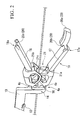
- FIG. 1 shows a guidewire catheter 1 according to the present embodiment.
- the guidewire catheter 1 is provided with: an insertion section 2 which will be inserted into a body via an endoscope; an operation section 3 connected to the insertion section 2; and a guidewire adapter 4 connected to the operation section 3.
- the insertion section 2 is a tubular sheath 6 allowing the guidewire 5 to be inserted therethrough and to extend or retract freely therethrough.
- a guidewire has various outer diameters, the most commonly used outer diameter of the guidewire is, for example, 0.035 inch (0.89 mm); and the appropriate range of the inner diameter of sheath 6 in this case is 0.9 mm to 1.2 mm.
- the guidewire may have more reduced outer diameters such as 0.025 inch (0.64 mm) or 0.018 inch (0.46 mm); and the appropriate ranges of inner diameter of sheaths in these cases may be 0.7 mm to 0.8 mm and 0.5 mm to 0.6 mm respectively.
- the space in the sheath 6 is designed to not only allow the guidewire 5 to be inserted therethrough but also supply various kinds of liquid including contrast agent or physiological saline.
- the operation section 3 is provided with a cylinder section 7 which allows the guidewire 5 to be inserted therethrough and to extend or retract freely therethrough.
- a connection port 7a is formed around the outer periphery of one end of the cylinder section 7.
- the sheath 6 connected to the connection port 7a is further inserted through the connection port 7a.
- An end of a bend-proof pipe 8 can be fixed to the connection port 7a.
- a port 7b which is a part of a commonly-known leur lock mechanism, is formed around the outer periphery of the other end of the cylinder section 7.
- the port 7b is designed to allow an end of a liquid-supply instrument including a syringe or the like that is adaptable to the leur lock mechanism to be connected thereto directly or via an appropriate adapter.
- a through-hole 7c is formed in the cylinder section 7 along the axial line (see FIG. 3 ).
- the inner wall section therein has an inner diameter which increases from the connection port 7a to the port 7b.
- a coupler section 3a which is connectible with an endoscope or the like is formed on the operation section 3.
- connection section 3 and the guidewire adapter 4 connected by the connection section 4b are freely extendable or retractable.
- the connection mechanism 9 is provided with a bar-shaped slide section 10 and a receiver section 11. An end of the slide section 10 is connected to the guidewire adapter 4.
- the receiver section 11 provided in the exterior of the through-hole 7c of the operation section 3 engages with the outer periphery of the slide section 10 and allows the slide section 10 to extend or retract freely.
- the slide section 10 is designed so that a distal end section 10a is inserted toward the receiver section 11.
- a stopper 12 formed on the side wall section of the distal end section 10a engages with the receiver section 11.
- the stopper 12 is designed to deform elastically and move inward with respect to the radial direction of the slide section 10 upon inserting the distal end section 10a of the slide section 10 into the receiver section 11 or detaching the stopper 12 from the distal end section 10a of the slide section 10.
- the stopper 12 prevents the slide section 10 from falling off from the receiver section 11 by limiting the movement of the slide section 10 relative to the receiver section 11 when the slide section 10 is inserted into the receiver section 11 and moves regressively (i.e., proximally relative to a user).
- a click section 13 formed on a part of the side surface of the slide section 10 is capable of engaging with the receiver section 11.
- the click section 13 projecting outward with respect to the radial direction of the slide section 10 is capable of making elastic deformation inward with respect to the radial direction of the slide section 10.
- the slide section 10 has a proximal end section 10b having a connection section 14 projecting outward with respective to the radial direction of the slide section 10.
- the cross-sectional shape of a second through-hole 15 formed on the connection section 14 is circular, and the diameter thereof is greater than the diameter of the cylinder section 7.
- the axial line of the second through-hole 15 is disposed along the axial line of the slide section 10. In this configuration, the axial line of the second through-hole 15 is adjustable to be coaxially with the axial line of the cylinder section 7 when the slide section 10 is connected to the receiver section 11.
- a distal end section 4a of the guidewire adapter 4 inserted into and supported by the connection section 14 is freely rotatable around the axial line.
- An opening section 16 having a diameter greater than the diameter of the cylinder section 7 is formed on the distal end section 4a of the guidewire adapter 4.
- a grip section 19 grasped by an operator includes a pair of proximally extending arms 17 and 18 provided on the distal end section 4a of the guidewire adapter 4.
- the arm 17 and the arm 18 each are formed unitarily with the distal end section 4a.
- the connection sections 4b that connect the arm 17 to the distal end section 4a and a connection section 4c that connects the arm 18 to the distal end section 4a are formed thinner to have resiliency and flexibility.
- a proximal end section 17a of the arm 17 and a proximal end section 18a of the arm 18 are formed to be separable from each other.
- the arm 17 and the arm 18 are designed so that the proximal end section 17a and the proximal end section 18a upon being compressed into close proximity provides elastic deformation to the connection section 4b, thereby causing the arm 17 to sway around the connection section 4b and the arm 18 to sway around the connection section 4c.
- hooks 20 for fixing the proximate state of the arm 17 and the arm 18 are formed on the proximal end section 17a and the proximal end section 18a.
- the hooks 20 includes: a projection section 20a further projecting from the proximal end of the proximal end section 17a of the arm 17; an engagement section 20b having a projection; and a mating-engagement section 20c, formed on the proximal end section 18a of the arm 18, that engages with the engagement section 20b.
- a pair of clasping sections 21 are formed on a part of the surface of the arm 17 and on a part of the surface of the arm 18 opposing the arm 17.
- the clasping sections 21 are capable of making contact with the guidewire 5 inserted into the opening section 16.
- the clasping sections 21 include: a wall section 21a projecting from the arm 17 toward the arm 18 substantially orthogonal with respect to the axis of the arm 17; a wall section 21b projecting from the arm 18 toward the arm 17 substantially orthogonal with respect to the axis of the arm 18; and a recessed section 21c formed on the wall section 21b opposed to the center section of the wall section 21a.
- the wall section 21a has a V-letter shape having the projection height lowering inward with respect to the radial direction of the arm 17.
- the size of the recessed section 21c is substantially the same as the diameter of the guidewire 5.
- the guidewire catheter 1 is prepared while an end of the guidewire 5 inserted in orders, into the opening section 16, the cylinder section 7, and the sheath 6 is projected from the distal end of the sheath 6.
- the length of the guidewire 5 projecting from the sheath 6 is adjusted appropriately.
- an endoscope 31 inserted from a natural orifice of a patent (i.e. a mouth) into the body of the patient is moved to the descending part of duodenum.
- a side-view endoscope 31 having an observation apparatus on its lateral side can be used in the present embodiment.
- the insertion section 2 of the guidewire catheter 1 inserted into a forceps-insertion port of the endoscope 31 disposed proximally in the vicinity of a user passes in an instrument channel to reach a distal end 32 of the endoscope 31. It is preferable that the distal end of the guidewire 5 in this state project from the distal end of the sheath 6 by 2 to 3 millimeters.
- the user grasps the grip section 19 disposed proximally relative to the guidewire adapter 4. Subsequently, the pair of arms 17 and 18 opposing each other are compressed to move in proximity with each other.
- the guidewire 5 is pinched between the wall section 2 1 a and the wall section 21b of the clasping section 21 in this state. Subsequently, the guidewire 5 upon being compressed by the wall section 21a having the V-letter-shape of inclinations as shown in FIG. 2 moves and shifts along the inclination to a central part of the wall section 21a.
- the guidewire 5 having moved and shifted toward the central part of the recessed section 21c engages with the recessed section 21c of the wall section 21b that opposes the wall section 21a.
- the guidewire 5 upon being fixed by the hook 20 using the clasping section 21 can be extended, retracted, or rotated with respect to the operation section 3 by extending, retracting, or rotating the grip section 19 with respect to the operation section 3.
- Moving the grip section 19 distally relative to the operation section 3 causes the connection mechanism 9 to guide the grip section 19, thereby moving the grip section 19 along the axial line of the cylinder section 7 of the operation section 3.
- This state of guidewire 5 while being fixed to the clasping section 21 and compressed along the axial line of the cylinder section 7 is allowed to make extending movement in the sheath 6 relative to the sheath 6.
- the user extends or retracts the guidewire 5 by extending or retracting the grip section 19 relative to the operation section 3. Subsequently, the user inserts the distal end of the guidewire 5 into the opening section of a nipple DN.
- a position that enables the insertion of the distal end of the guidewire 5 may be located by extending or retracting the grip section 19 and searching for the opening section of the nipple DN so that the distal end of the guidewire 5 makes contact with the vicinity of the nipple DN.
- the sheath 6 together with the guidewire 5 are extended from the distal end 32 of the endoscope 31 by moving the operation section 3 distally. Accordingly, the sheath 6 is inserted through the opening section of the nipple DN into the bile duct BD.
- FIG. 9 shows the guidewire catheter 1 from which the guidewire 5 has been removed.
- elastic deformation is applied to the projection section 20a to release the engagement between the engagement section 20b and the mating-engagement section 20c.
- the elasticity of the connection section 4b connected to the arm 17 and the elasticity of the connection section 4c connected to the arm 18 cause the arm 17 and the arm 18 to move in directions that separate them from each other. This releases the fixed state of the guidewire 5 by the wall section 21a and the wall section 21b, thereby rendering the guidewire 5 freely extendable or retractable.
- the guidewire 5 projecting from the opening section 16 is retracted proximally by the user.
- the guidewire 5 can be so removed from the guidewire catheter 1.
- the distal end of the sheath 6 in this state remains immovable and resides in the bile duct BD.
- the grip section 19 upon removing the guidewire 5 is further extended relative to the operation section 3.
- the slide section 10 in this state is allowed to be inserted farther into the receiver section 11 relative to the position as shown in FIG 7 .
- the click section 13 elastically deformable in this state is allowed to make extending or retracting movement while compressing the inner wall of the receiver section 11. Friction produced between the click section 13 and the receiver section 11 limits the extension or retraction of this state of the operation section 3 and the guidewire adapter 4.
- the cylinder section 7 of the operation section 3 is allowed to pass through the opening section 16.
- the user can connect a syringe 30, filled with a contrast agent, to this state of the port 7b projecting proximally toward the grip section 19.
- the distal end of the syringe 30 is brought into close contact with the port 7b by compressing the syringe 30 to the port 7b and rotating the syringe 30 around the axial line of the port 7b since the distal end of the syringe 30 has a leur lock structure that conforms to the port 7b.
- the contrast agent supplied from the syringe 30 through the port 7b passes in order, through the cylinder section 7, the sheath 6, and the distal end of the sheath 6, and is injected into the bile duct BD.
- the user captures roentgenologic contrast radiographic images of the bile duct BD filled with the contrast agent thereinside.
- the guidewire catheter 1 is removed to finish the treatment.
- a conventional guidewire catheter has used an apparatus commonly called a torque device that is an operation assistant instrument for assisting operation including the extension or the retraction of a guidewire inserted through a sheath by fixing the outer periphery surface of the guidewire.
- a torque device that is an operation assistant instrument for assisting operation including the extension or the retraction of a guidewire inserted through a sheath by fixing the outer periphery surface of the guidewire.
- the important point to note is that the insertion of guidewire into the sheath with the torque device necessitates the guidewire to be inserted straight into a proximal opening of the sheath in order to prevent the guidewire from bending.
- Another problem was that, leaving a hand from the torque device during a process of treatment might sometimes cause the guidewire to hang over by the self weight thereof, thereby hindering the maneuver.
- Japanese Unexamined Patent Application, First Publication No. 2003-79741 discloses another guidewire adapter that uses a freely slidable elongated tubular guide member inserted through a lumen of a through-hole of a tubular member that allows a guidewire to pass therethrough.
- a stroke length e.g. 7 cm
- the lumen of the tubular member to have a length that accommodates the full stroke length of the slidable member. Therefore, adding up the lengths of the receiver and the slide section obtains at least a doubled stroke length which will be problematic because it is too long in view of operability.
- a stroke length of 7 cm the sum of lengths of the receiver and the slide section is at least 14 cm.
- the present application has an advantageous operability because the sum of the lengths of the receiver and the slide section can be substantially the same as the stroke length, and the guidewire adapter can be compact when it is attached to the operation section since the slide member is disposed in line with and in the exterior of a through-hole which allows a guidewire to pass therethrough.
- the guidewire catheter 1 is designed so that the connection mechanism 9 connects the operation section 3 to the guidewire adapter 4, and so that the guidewire adapter 4 extends or retracts along the axial line of the cylinder section 7. This allows the guidewire 5 gripped by the guidewire adapter 4 to be inserted into the sheath 6 to be free from bending.
- a second embodiment of the present invention will be explained next with reference to FIGS. 10 to 17 .
- a guidewire catheter of the present embodiment is different from the aforementioned guidewire catheter 1 based on the configuration of the guidewire adapter.
- a guidewire catheter 100 according to the second embodiment is configured to include a guidewire adapter 40 in place of the guidewire adapter 4 according to the first embodiment.
- the configuration of the guidewire adapter 40 is different from that of the guidewire adapter 4 according to the first embodiment because the guidewire adapter 40 is provided with: a cylindrical main unit 41 that allows the guidewire 5 to pass therethrough and is capable of communicating with the lumen of the sheath 6; a seal mechanism 42, connected to the proximal end section of the main unit 41, that allows the guidewire 5 to pass therethrough and seals the proximal opening of the main unit 41; a sideport 43 that communicates with the lumen between the sheath 6 and the seal mechanism 42; and a pair of arms 47 and 48, connected to the seal mechanism 42 and opposed in the radial direction in the exterior of the of the guidewire, that grasp the guidewire 5
- the distal end of the main unit 41 is inserted into the second through-hole 15 of the connection section 14, and the main unit 41 is locked in this state.
- the main unit 41 is freely rotatable around the axial line of the second through-hole 15 relative to the connection section 14.
- the axial line of the cylinder section 7 is configured to be substantially coaxial with the axial line of the main unit 41 when the main unit 41, the connection mechanism 9, and the operation section 3 are assembled together.
- a leur lock section 45 formed on the distal end section of the main unit 41, is connected with the port 7b of the cylinder section 7. In this configuration, the leur lock mechanism provides waterproof connection by connecting the cylinder section 7 and the main unit 41 seamlessly.
- the seal mechanism 42 is provided with a seal member 46 and a pusher 51.
- the seal member 46 is made from an elastic member provided to the proximal end of the main unit 41.
- the pusher 51 has link mechanisms 49 and 50, disposed proximal relative to the seal member 46, that are connected to the pair of arms 47 and 48 respectively.
- the distal end of the cylindrical seal member 46 made of an elastic material, for example, rubber is inserted into the main unit 41.
- the inner wall of the seal member 46 has a substantial conical surface that inclines outward from the proximal end to the distal end thereof with respect to the radial direction.
- the guidewire 5 inserted through the seal member 46 is freely extendable or retractable in this configuration.
- the pusher 51 is disposed coaxially with the proximal end of the seal member 46.
- the pusher 51 includes: a pusher plate 52, formed in the proximal end of the seal member 46, that is capable of making contact with the proximal end of the seal member 46; a pusher main unit section 53 having a cylindrical shape in the vicinity of the proximal end of the pusher plate 52; and link mechanisms 49 and 50 that connect the arms 47 and 48 respectively to the outer periphery surface of the pusher main unit section 53.
- a through-hole 54 formed through the pusher plate 52 and the pusher main unit section 53 coaxially with the axial line of the main unit 41 allows the guidewire 5 to freely extend or retract therethrough.
- the through-hole 54 formed in the pusher main unit section 53 has a substantial conical shape that increases the radial direction outwardly toward the proximal end thereof. That is, the diameter of the opening formed on the proximal end section of the pusher main unit section 53 is greater than the diameter of the opening formed on the distal end section of the pusher main unit section 53. Therefore, in this configuration, an end of the guidewire 5 inserted into the proximal end section of the pusher main unit section 53 is guided through the through-hole 54 and inserted into the seal member 46 via a pusher plate 52.
- link mechanisms 49 and 50 are sheet plates that are formed with the arms 47 and 48 and the pusher main unit section 53 unitarily so that sections that connect the arms 47 and 48 to the pusher main unit section 53 are swayable respectively.
- a through-hole 55 formed in the sideport 43 reduces its inner diameter toward the distal end of the main unit 41 and communicates with the inner space in the main unit.
- a commonly known leur lock mechanism is applicable to an outer periphery section 58 formed on the proximal opening of the sideport 43.
- the sideport 43 is designed to allow a section of a liquid-supply instrument including a syringe or the like that is adaptable to the leur lock mechanism to be connected thereto directly or via an appropriate adapter.
- the arm 47 and the arm 48 of the present embodiment having the hooks 20 are similar to the first embodiment.
- a lock section 20d that locks the guidewire 5 is formed on the projection section 20a in the present embodiment (see FIG. 10 ).
- the clasping section 21 has a pair of opposing corrugated surfaces 56 and 57 in place of the wall sections 21a and 21b. In this configuration, the corrugated surfaces 56 and 57 prevent the guidewire 5 from slipping.
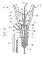
- FIG. 12 shows the guidewire catheter 100 prepared by inserting the guidewire 5 into the proximal end of the pusher main unit section 53 and through the seal member 46 and the main unit 41, and further through the cylinder section 7 and the sheath 6 as shown in FIG 13 .
- the user extends the endoscope 31 to the descending part of duodenum and adjusts the visual field to include the nipple DN. Subsequently, when the user grips the arms 47 and 48 of the guidewire adapter 40, the opposing arms 47 and 48 are compressed to come close to each other
- the outer periphery surface of the guidewire 5 is grasped by the corrugated surfaces 56 and 57 of the clasping section 21.
- the hooks 20 fix the proximate state of arms 47 and 48.
- the guidewire 5 in this state is fixed by the clasping section 21.
- the link mechanisms 49 and 50 connected to the arms 47 and 48 respectively are compressed by swayable movement around connecting sections 40b and 40c.
- the connecting section 40b connects the arm 47 to the guidewire adapter 40
- the connecting section 40c connects the arm 48 to the guidewire adapter 40.
- the distal end section of the seal member 46 makes close contact with a rim section 41a formed on the proximal opening of the main unit, and the through-hole formed along the axial line of the seal member 46 contracts to make close contact with the outer periphery section of the guidewire 5. Accordingly, the proximate and fixed state of arms 47 and 48 causes the main unit 41, the guidewire 5, and the seal member 46 to make close contact with each other, thereby providing waterproof state therebetween.
- the user grasping the grip section 19 inserts the distal end of the guidewire 5 into the opening section of the nipple DN by extending, retracting, or rotating the guidewire 5.
- the distal end of the sheath 6 is inserted into the bile duct BD along the guidewire 5 via the opening section of the nipple DN.
- connection mechanism 9 is configured to move the guidewire adapter 40 linearly along the axial line of the cylinder section 7 when the grip section 19 is extended or retracted.
- inadvertent connection between the port 7b the leur lock section 45 is prevented when the grip section 19 is moved or rotated since the port 7b of the operation section 3 is configured not to make contact with the leur lock section 45 of the guidewire adapter 40 at a position where the click section 13 formed on the slide section 10 makes contact with the receiver section 11.
- the user fastens the leur lock section 45 of the guidewire adapter 40 into the port 7b of the cylinder section 7 of the operation section 3 while further compressing the slide section 10 toward the operation section 3.
- This provides waterproof connection between the port 7b and the leur lock section 45.
- the user attaches the syringe 30 filled with the contrast agent to the sideport 43.
- the contrast agent is supplied from the syringe 30 into the main unit 41 via the through-hole 55 of the sideport 43.
- the contrast agent moves toward the distal end of the main unit since the proximal end of the main unit 41 maintains the waterproof condition while the arms 47 and 48 are fixed by the hooks 20.
- the contrast agent passing through a gap between the guidewire 5, the cylinder section 7, and the sheath 6 and supplied to the distal end of the sheath 6 is ejected from the distal end of the sheath 6 into the bile duct BD.
- the user captures roentgenologic contrast radiographic images of the bile duct BD filled with the contrast agent thereinside.
- the guidewire 5 and the guidewire catheter 100 are removed to finish the treatment.
- a gripping movement conducted to the arms 47 and 48 of the guidewire adapter 40 simultaneously causes an operation for fixing the guidewire 5 and an operation for maintaining the waterproof state between the guidewire 5 and the main unit 41 in the vicinity of the user's hand, thereby facilitating the operations.
- FIGS. 18 to 20 A third embodiment of the present invention will be explained next with reference to FIGS. 18 to 20 .
- a guidewire catheter 300 has a configuration different from that of the first embodiment because incised sections 60 and 61 are formed on the connection section 14 of the connection mechanism 9 and the distal end section 4a of the guidewire adapter 4 respectively.
- connection section 14 engages with the distal end section 4a so that the two components are freely rotatable with each other. Therefore, in this configuration, the positions of the incised sections 60 and 61 are variable between a connecting state or a disconnecting state of the connection section 14 relative to the distal end section 4a.
- the guidewire adapter 4 is rotated around the axial line in the circumferential direction relative to the connection section 14 to coincide the incised sections 60 and 61. Subsequently, the guidewire 5 is inserted into the opening section 16 via the incised sections 60 and 61.
- the insertion of the guidewire catheter 300 into the guidewire 5 can be facilitated since the guidewire 5 can be inserted into the lateral side of the opening section 16.
- the guidewire 5 is maintained in the opening section 16 unless the position of the incised section 60 coincides with the position of the incised section 61 in the circumferential direction.
- a fourth embodiment of the present invention will be explained next with reference to FIG. 21 .
- a guidewire catheter 400 according to the present embodiment is supposed to be used with various endoscopically usable instruments. As shown in FIG. 21 , the guidewire catheter 400 has a configuration different from that of the first embodiment because the guidewire catheter 400 is provided with a holder section 70 for fixing and holding an instrument X.
- a conceivable example for the instrument X may be a high-frequency knife or the like for incising the nipple DN.
- This case of the sheath 6 can be used with one of lumens of the high-frequency knife into which the sheath 6 is inserted, of the sheath 6 can be disposed along the tube of the high-frequency knife.
- This configuration reduces complexity in operations using the guidewire catheter together with the instrument X since the guidewire catheter 400 and the instrument X can be used as a single component.
- the proximal end section of the pusher 51 can be extended to form a cam structure that makes contact with the arm 47 and the arm 48 and compresses the pusher main unit section 53 by means of the arm 47 and the arm 48.
- connection mechanism 9 including the receiver section 11 provided on the operation section 3 and the slide section 10 having the connection section 14.
- a configuration including a bar-shaped slide section provided to the operation section 3 and a receiver having the connection section 14 can achieve the same effect as that of the present invention.
- FIGS. 22 and 23 show a configuration using a catheter 500 having a lumen 501 used for taking contrast radiographic images and a guidewire lumen 502 having an opening provided in the middle of the catheter 500 in which the receiver section 11 is fixed in the vicinity of the exterior of an insertion port 505a of an instrument channel 505 which allows the insertion of the catheter 500 into the endoscope 504.
- Moving the guidewire adapter 4, which is extendable or retractable relative to the endoscope 504, while maintaining the catheter 500 immovable relative to the endoscoope 504 allows the guidewire 5 to extend or retract relative to the catheter 500.
- the guidewire adapter 4 does not necessitate the operation section of the endoscope 504 that is large in size since the receiver section 11 is provided in the exterior of the instrument channel 505 of the endoscope 504.
- the configuration of the present invention is not limited to the second embodiment adopting the sideport 43 communicating to the space in the main unit 41, and a configuration adopting the sideport 43 disposed to communicate with the space from the outer periphery surface of the cylinder section 7 can achieve the same effect as that of the present invention.
Abstract
Description
- The present invention relates to a guidewire catheter for use with a guidewire for guiding a catheter. More specifically, the present invention relates to a guidewire catheter for use with an adapter for assisting the insertion or the rotation of a guidewire for guiding a catheter endoscopically inserted into a body cavity and used for regressively injecting liquid into a bile duct or a pancreatic duct.
- Priority is claimed on U.S.A Patent Application No.
12/202,494 filed September 2, 2008 - Endoscopic retrograde cholangiopancreatography (ERCP) is a conventionally-known diagnostic method for finding an abnormality in a pancreas, a cholecyst, or a bile duct. The ERCP provides X-ray photography by inserting a catheter into the nipple of a duodenum and subsequently injecting a contrast agent directly into a pancreatic duct or a bile duct.
- However, in some cases, the insertion of the catheter into the bile duct is difficult when the entrance of the nipple is narrow, or when the bile duct is bending. Pushing the catheter into the entrance of the nipple with an excessive force in this case may cause endema on the mucosa thereof, thereby resulting in a further narrowing the entrance.
- A contrast agent injected from the catheter upon being entered deeper relative to the mucosa and blocking a port of the pancreatic duce may prevents the drainage of pancreatic fluid, thereby increasing the possibility of developing pancreatitis therein. To address this, a conventional method for finding a bile duct uses a guidewire having a relatively bendable flexible distal end while being projected from the distal end of the catheter by 2 to 3 millimeters.
- Some known apparatuses for guiding a catheter in such operations use a guidewire having a diameter smaller than a catheter. For example, Japanese Unexamined Patent Application, First Publication No.
H8-257134 - The operation assistant instrument for the medical-use guidewire having a groove capable of approaching to or separating from each other in the axial direction is designed to allow a guidewire to be inserted into the groove and to fix the medical-use guidewire in the operation assistant instrument. The operation assistant instrument for use with the medical guidewire is capable of attaching the operation assistant instrument to the guidewire, changing the position of the operation assistant instrument, and easily detaching of the guidewire from the operation assistant instrument. In addition, the operation assistant instrument is capable of inserting the guidewire into the lumen of an object tissue by extending or retracting the guidewire, or by rotating the guidewire around the axial line.
- A first aspect of the present invention is a guidewire catheter which includes: a sheath for passing a guidewire therethrough; an operation section connected to an end of the sheath and having a through-hole for passing the guidewire therethrough; a guidewire adapter connected to the operation section and capable of freely extending or retracting relative to the operation section along an axial line of the through-hole, the guidewire adapter grasping the outer periphery surface of the guidewire projecting from the through-hole, and the guidewire adapter being capable of guiding and moving the guidewire relative to the operation section in an axial direction and a circumferential direction of the through-hole; a bar-shaped slide section formed on one of the operation section and the guidewire adapter in the exterior of the through-hole, the slide section being disposed along a line which is parallel with the axial line of the through-hole; a receiver formed on the other one of the operation section and the guidewire adapter and being capable of moving and supporting the freely extendable or retractable slide section; a connection section having a second through-hole formed coaxially with the axial line of the through-hole; and a grip section, engaged with the second through-hole, for grasping an outer periphery surface of the guidewire, and the grip section being freely rotatable around the axial line of the second through-hole.
- A second aspect of the present invention is a guidewire catheter which includes: a sheath for passing a guidewire therethrough; an operation section connected to an end of the sheath and having a through-hole for passing the guidewire therethrough; and a guidewire adapter connected to the operation section and capable of freely extending or retracting relative to the operation section along the axial line of the through-hole, the guidewire adapter grasping the outer periphery surface of the guidewire projecting from the through-hole, and the guidewire adapter being capable of guiding and moving the guidewire relative to the operation section in an axial direction and a circumferential direction of the through-hole, wherein the guidewire adapter includes: a cylindrical main unit passing the guidewire adapter therethrough and being capable of communicating with the inside of the sheath; a seal mechanism, connected to a proximal end section of the main unit and passing the guidewire therethrough, for sealing a proximal opening formed on the main unit; a sideport communicating with a space in the sheath and the seal mechanism; a pair of arms connected to the seal mechanism and opposed in a radial direction in the exterior in a circumferential direction of the guidewire, the pair of arms each having a fixture surface for grasping the guidewire, and the pair of arms being capable of swaying so that the pair of fixture surfaces approach to or separate from each other; and a hook for fixing the pair of arms while the guidewire is compressed and fixed by the fixture surfaces, wherein the seal mechanism includes: a seal member made of an elastic member and provided to the proximal end of the main unit; and a pusher having a link mechanism disposed proximally relative to the seal member and connected to at least one of the pair of arms, and wherein the pusher linking with swayable movement of the pair of arms compresses the seal member.
- A third aspect of the present invention is a guidewire catheter which includes: a sheath for passing a guidewire therethrough; an operation section connected to an end of the sheath and having a through-hole for passing the guidewire therethrough; a guidewire adapter connected to the operation section and capable of freely extending or retracting relative to the operation section along the axial line of the through-hole, the guidewire adapter grasping the outer periphery surface of the guidewire projecting from the through-hole, and the guidewire adapter being capable of guiding and moving the guidewire relative to the operation section in an axial direction and a circumferential direction of the through-hole; a bar-shaped slide section formed on one of the operation section and the guidewire adapter in the exterior of the through-hole, the slide section being disposed along a line which is parallel with the axial line of the through-hole; a receiver formed on the other one of the operation section and the guidewire adapter and being capable of moving and supporting the freely extendable or retractable slide section; a connection section having a second through-hole formed coaxially with the axial line of the through-hole; a grip section, engaged with the second through-hole, for grasping an outer periphery surface of the guidewire, and the grip section being freely rotatable around the axial line of the second through-hole; a first incised section formed by incising an outer wall section of the connection section in the axial direction thereof; and a second incised section formed by incising an outer wall section of the grip section in the axial direction thereof, wherein rotational positions of the first incised section and the second incised section are variable between a connecting state or a disconnecting state of the connection section with respect to the grip section.
-
-
FIG 1 shows a guidewire catheter according to a first embodiment of the present invention. -
FIG 2 is an enlarged view of the guidewire adapter of the guidewire catheter. -
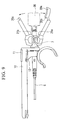
FIG 3 is a fragmentary sectional view of the guidewire catheter. -
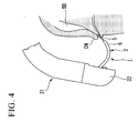
FIG 4 shows a process of maneuver in the ERCP using the guidewire catheter. -
FIG 5 shows the guidewire catheter in use. -
FIG 6 shows the guidewire catheter in use. -
FIG 7 shows a click section when the guidewire catheter is used. -
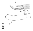
FIG 8 shows a process of maneuver in the ERCP using the guidewire catheter. -
FIG 9 shows the guidewire catheter in use. -
FIG. 10 shows a guidewire catheter according to a second embodiment of the present invention. -
FIG. 11 shows a guidewire catheter according to the second embodiment of the present invention. -
FIG 12 is an enlarged cross-sectional view of the guidewire adapter of the guidewire catheter. -
FIG 13 shows the movement of the guidewire adapter of the guidewire catheter. -
FIG 14 shows the movement of the guidewire adapter of the guidewire catheter. -
FIG 15 shows the movement of the guidewire catheter in use. -
FIG. 16 shows the movement of the guidewire catheter in use. -
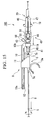
FIG 17 is a fragmentary cross-sectional view showing the movement of the guidewire adapter of the guidewire catheter in use. -
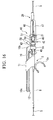
FIG. 18 shows a the guidewire catheter according to a third embodiment of the present invention. -
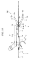
FIG 19 shows the movement of the guidewire catheter in use as shown inFIG 18 . -
FIG 20 shows the movement of the guidewire catheter in use as shown inFIG 18 . -
FIG 21 shows the guidewire catheter according to a fourth embodiment of the present invention. -
FIG 22 shows a modified example of the guidewire catheter according to the present invention. -
FIG 23 shows the movement of the guidewire catheter in use as shown inFIG 22 . - A guidewire catheter according to a first embodiment of the present invention will be explained with reference to
FIGS. 1 to 9 as follows. -
FIG. 1 shows aguidewire catheter 1 according to the present embodiment. Theguidewire catheter 1 is provided with: aninsertion section 2 which will be inserted into a body via an endoscope; anoperation section 3 connected to theinsertion section 2; and aguidewire adapter 4 connected to theoperation section 3. - The
insertion section 2 is atubular sheath 6 allowing theguidewire 5 to be inserted therethrough and to extend or retract freely therethrough. While a guidewire has various outer diameters, the most commonly used outer diameter of the guidewire is, for example, 0.035 inch (0.89 mm); and the appropriate range of the inner diameter ofsheath 6 in this case is 0.9 mm to 1.2 mm. The guidewire may have more reduced outer diameters such as 0.025 inch (0.64 mm) or 0.018 inch (0.46 mm); and the appropriate ranges of inner diameter of sheaths in these cases may be 0.7 mm to 0.8 mm and 0.5 mm to 0.6 mm respectively. - In addition, the space in the
sheath 6 is designed to not only allow theguidewire 5 to be inserted therethrough but also supply various kinds of liquid including contrast agent or physiological saline. - The
operation section 3 is provided with acylinder section 7 which allows theguidewire 5 to be inserted therethrough and to extend or retract freely therethrough. Aconnection port 7a is formed around the outer periphery of one end of thecylinder section 7. Thesheath 6 connected to theconnection port 7a is further inserted through theconnection port 7a. An end of a bend-proof pipe 8 can be fixed to theconnection port 7a. - A
port 7b, which is a part of a commonly-known leur lock mechanism, is formed around the outer periphery of the other end of thecylinder section 7. Theport 7b is designed to allow an end of a liquid-supply instrument including a syringe or the like that is adaptable to the leur lock mechanism to be connected thereto directly or via an appropriate adapter. - In addition, a through-
hole 7c is formed in thecylinder section 7 along the axial line (seeFIG. 3 ). The inner wall section therein has an inner diameter which increases from theconnection port 7a to theport 7b. - In addition, a
coupler section 3a which is connectible with an endoscope or the like is formed on theoperation section 3. - The
operation section 3 and theguidewire adapter 4 connected by theconnection section 4b are freely extendable or retractable. Theconnection mechanism 9 is provided with a bar-shaped slide section 10 and areceiver section 11. An end of theslide section 10 is connected to theguidewire adapter 4. Thereceiver section 11 provided in the exterior of the through-hole 7c of theoperation section 3 engages with the outer periphery of theslide section 10 and allows theslide section 10 to extend or retract freely. - The
slide section 10 is designed so that adistal end section 10a is inserted toward thereceiver section 11. In addition, astopper 12 formed on the side wall section of thedistal end section 10a engages with thereceiver section 11. Thestopper 12 is designed to deform elastically and move inward with respect to the radial direction of theslide section 10 upon inserting thedistal end section 10a of theslide section 10 into thereceiver section 11 or detaching thestopper 12 from thedistal end section 10a of theslide section 10. Thestopper 12 prevents theslide section 10 from falling off from thereceiver section 11 by limiting the movement of theslide section 10 relative to thereceiver section 11 when theslide section 10 is inserted into thereceiver section 11 and moves regressively (i.e., proximally relative to a user). - In addition, a
click section 13 formed on a part of the side surface of theslide section 10 is capable of engaging with thereceiver section 11. Theclick section 13 projecting outward with respect to the radial direction of theslide section 10 is capable of making elastic deformation inward with respect to the radial direction of theslide section 10. - In addition, the
slide section 10 has aproximal end section 10b having aconnection section 14 projecting outward with respective to the radial direction of theslide section 10. The cross-sectional shape of a second through-hole 15 formed on theconnection section 14 is circular, and the diameter thereof is greater than the diameter of thecylinder section 7. The axial line of the second through-hole 15 is disposed along the axial line of theslide section 10. In this configuration, the axial line of the second through-hole 15 is adjustable to be coaxially with the axial line of thecylinder section 7 when theslide section 10 is connected to thereceiver section 11. - As shown in
FIG. 2 , adistal end section 4a of theguidewire adapter 4 inserted into and supported by theconnection section 14 is freely rotatable around the axial line. Anopening section 16 having a diameter greater than the diameter of thecylinder section 7 is formed on thedistal end section 4a of theguidewire adapter 4. In addition, agrip section 19 grasped by an operator includes a pair of proximally extendingarms distal end section 4a of theguidewire adapter 4. - As shown in
FIGS. 2 and3 , thearm 17 and thearm 18 each are formed unitarily with thedistal end section 4a. Theconnection sections 4b that connect thearm 17 to thedistal end section 4a and aconnection section 4c that connects thearm 18 to thedistal end section 4a are formed thinner to have resiliency and flexibility. In addition, aproximal end section 17a of thearm 17 and aproximal end section 18a of thearm 18 are formed to be separable from each other. - The
arm 17 and thearm 18 are designed so that theproximal end section 17a and theproximal end section 18a upon being compressed into close proximity provides elastic deformation to theconnection section 4b, thereby causing thearm 17 to sway around theconnection section 4b and thearm 18 to sway around theconnection section 4c. In addition, hooks 20 for fixing the proximate state of thearm 17 and thearm 18 are formed on theproximal end section 17a and theproximal end section 18a. - As shown in
FIG. 2 , thehooks 20 includes: aprojection section 20a further projecting from the proximal end of theproximal end section 17a of thearm 17; anengagement section 20b having a projection; and a mating-engagement section 20c, formed on theproximal end section 18a of thearm 18, that engages with theengagement section 20b. - In addition, as shown in
FIG. 2 , a pair of claspingsections 21 are formed on a part of the surface of thearm 17 and on a part of the surface of thearm 18 opposing thearm 17. The claspingsections 21 are capable of making contact with theguidewire 5 inserted into theopening section 16. The claspingsections 21 include: awall section 21a projecting from thearm 17 toward thearm 18 substantially orthogonal with respect to the axis of thearm 17; awall section 21b projecting from thearm 18 toward thearm 17 substantially orthogonal with respect to the axis of thearm 18; and a recessedsection 21c formed on thewall section 21b opposed to the center section of thewall section 21a. - In addition, the
wall section 21a has a V-letter shape having the projection height lowering inward with respect to the radial direction of thearm 17. In addition, the size of the recessedsection 21c is substantially the same as the diameter of theguidewire 5. - Operation in ERCP using the
guidewire catheter 1 having the aforementioned configuration will be explained with reference toFIGS. 3 to 9 . - As shown in
FIGS. 1 and3 , theguidewire catheter 1 is prepared while an end of theguidewire 5 inserted in orders, into theopening section 16, thecylinder section 7, and thesheath 6 is projected from the distal end of thesheath 6. The length of theguidewire 5 projecting from thesheath 6 is adjusted appropriately. - In the beginning, as shown in
FIG 4 , anendoscope 31 inserted from a natural orifice of a patent (i.e. a mouth) into the body of the patient is moved to the descending part of duodenum. A side-view endoscope 31 having an observation apparatus on its lateral side can be used in the present embodiment. - The
insertion section 2 of theguidewire catheter 1 inserted into a forceps-insertion port of theendoscope 31 disposed proximally in the vicinity of a user passes in an instrument channel to reach adistal end 32 of theendoscope 31. It is preferable that the distal end of theguidewire 5 in this state project from the distal end of thesheath 6 by 2 to 3 millimeters. - As shown in
FIG 5 , the user grasps thegrip section 19 disposed proximally relative to theguidewire adapter 4. Subsequently, the pair ofarms guidewire 5 is pinched between thewall section 2 1 a and thewall section 21b of theclasping section 21 in this state. Subsequently, theguidewire 5 upon being compressed by thewall section 21a having the V-letter-shape of inclinations as shown inFIG. 2 moves and shifts along the inclination to a central part of thewall section 21a. On the other hand, theguidewire 5 having moved and shifted toward the central part of the recessedsection 21c engages with the recessedsection 21c of thewall section 21b that opposes thewall section 21a. - Further compressing and moving the
arms hook 20 to fix the proximate state of thearm 17 and thearm 18. Theguidewire 5 in this state compressed and fixed by thewall section 21a and thewall section 21b results in being fixed by thegrip section 19. This state of theguidewire 5 is designed to be disposed on the axial line of thecylinder section 7 between thecylinder section 7 and theclasping section 21. - As shown in
FIG. 6 , theguidewire 5 upon being fixed by thehook 20 using theclasping section 21 can be extended, retracted, or rotated with respect to theoperation section 3 by extending, retracting, or rotating thegrip section 19 with respect to theoperation section 3. Moving thegrip section 19 distally relative to theoperation section 3 causes theconnection mechanism 9 to guide thegrip section 19, thereby moving thegrip section 19 along the axial line of thecylinder section 7 of theoperation section 3. This state ofguidewire 5 while being fixed to theclasping section 21 and compressed along the axial line of thecylinder section 7 is allowed to make extending movement in thesheath 6 relative to thesheath 6. - Consequently, moving the
guidewire 5 distally relative to thesheath 6 results in extending theguidewire 5 relative to the distal end section of thesheath 6. - As shown in
FIG. 7 , freely extending or retracting movement of theslide section 10 relative to thereceiver section 11 is limited by theclick section 13 which makes contact with the proximal end section of thereceiver section 11. Further compressing thegrip section 19 into theoperation section 3 while thearms hook 20 causes theclasping section 21 to make contact with theport 7b. The extending or retracting movement of the inner wall section of thereceiver section 11 compressed by theclick section 13 in this state is limited. - As shown in
FIG 8 , the user extends or retracts theguidewire 5 by extending or retracting thegrip section 19 relative to theoperation section 3. Subsequently, the user inserts the distal end of theguidewire 5 into the opening section of a nipple DN. In a case of not readily identifying the opening section, a position that enables the insertion of the distal end of theguidewire 5 may be located by extending or retracting thegrip section 19 and searching for the opening section of the nipple DN so that the distal end of theguidewire 5 makes contact with the vicinity of the nipple DN. - Upon inserting and passing the distal end of the
guidewire 5 through the nipple DN into a bile duct BD, thesheath 6 together with theguidewire 5 are extended from thedistal end 32 of theendoscope 31 by moving theoperation section 3 distally. Accordingly, thesheath 6 is inserted through the opening section of the nipple DN into the bile duct BD. - Upon inserting the
sheath 6 into the bile duct BD and reaching to an object site, theguidewire 5 is removed from theguidewire catheter 1.FIG. 9 shows theguidewire catheter 1 from which theguidewire 5 has been removed. In the beginning, elastic deformation is applied to theprojection section 20a to release the engagement between theengagement section 20b and the mating-engagement section 20c. Subsequently, the elasticity of theconnection section 4b connected to thearm 17 and the elasticity of theconnection section 4c connected to thearm 18 cause thearm 17 and thearm 18 to move in directions that separate them from each other. This releases the fixed state of theguidewire 5 by thewall section 21a and thewall section 21b, thereby rendering theguidewire 5 freely extendable or retractable. Theguidewire 5 projecting from theopening section 16 is retracted proximally by the user. Theguidewire 5 can be so removed from theguidewire catheter 1. The distal end of thesheath 6 in this state remains immovable and resides in the bile duct BD. - The
grip section 19 upon removing theguidewire 5 is further extended relative to theoperation section 3. Theslide section 10 in this state is allowed to be inserted farther into thereceiver section 11 relative to the position as shown inFIG 7 . Theclick section 13 elastically deformable in this state is allowed to make extending or retracting movement while compressing the inner wall of thereceiver section 11. Friction produced between theclick section 13 and thereceiver section 11 limits the extension or retraction of this state of theoperation section 3 and theguidewire adapter 4. - On the other hand, if the
guidewire adapter 4 is compressed fully into theoperation section 3, thecylinder section 7 of theoperation section 3 is allowed to pass through theopening section 16. The user can connect asyringe 30, filled with a contrast agent, to this state of theport 7b projecting proximally toward thegrip section 19. The distal end of thesyringe 30 is brought into close contact with theport 7b by compressing thesyringe 30 to theport 7b and rotating thesyringe 30 around the axial line of theport 7b since the distal end of thesyringe 30 has a leur lock structure that conforms to theport 7b. - The contrast agent supplied from the
syringe 30 through theport 7b passes in order, through thecylinder section 7, thesheath 6, and the distal end of thesheath 6, and is injected into the bile duct BD. The user captures roentgenologic contrast radiographic images of the bile duct BD filled with the contrast agent thereinside. Upon obtaining the roentgenologic images, theguidewire catheter 1 is removed to finish the treatment. - A conventional guidewire catheter has used an apparatus commonly called a torque device that is an operation assistant instrument for assisting operation including the extension or the retraction of a guidewire inserted through a sheath by fixing the outer periphery surface of the guidewire. However, the important point to note is that the insertion of guidewire into the sheath with the torque device necessitates the guidewire to be inserted straight into a proximal opening of the sheath in order to prevent the guidewire from bending. Another problem was that, leaving a hand from the torque device during a process of treatment might sometimes cause the guidewire to hang over by the self weight thereof, thereby hindering the maneuver.
- Japanese Unexamined Patent Application, First Publication No.
2003-79741 - The present application has an advantageous operability because the sum of the lengths of the receiver and the slide section can be substantially the same as the stroke length, and the guidewire adapter can be compact when it is attached to the operation section since the slide member is disposed in line with and in the exterior of a through-hole which allows a guidewire to pass therethrough.
- The
guidewire catheter 1 according to the present embodiment is designed so that theconnection mechanism 9 connects theoperation section 3 to theguidewire adapter 4, and so that theguidewire adapter 4 extends or retracts along the axial line of thecylinder section 7. This allows theguidewire 5 gripped by theguidewire adapter 4 to be inserted into thesheath 6 to be free from bending. - A second embodiment of the present invention will be explained next with reference to
FIGS. 10 to 17 . A guidewire catheter of the present embodiment is different from theaforementioned guidewire catheter 1 based on the configuration of the guidewire adapter. - It should be noted that configurations that are similar to those of the previously explained first embodiment will be assigned the same numeric symbol and redundant explanation thereof will be omitted.
- As shown in
FIGS. 10 and11 , aguidewire catheter 100 according to the second embodiment is configured to include aguidewire adapter 40 in place of theguidewire adapter 4 according to the first embodiment. - The configuration of the
guidewire adapter 40 is different from that of theguidewire adapter 4 according to the first embodiment because theguidewire adapter 40 is provided with: a cylindricalmain unit 41 that allows theguidewire 5 to pass therethrough and is capable of communicating with the lumen of thesheath 6; aseal mechanism 42, connected to the proximal end section of themain unit 41, that allows theguidewire 5 to pass therethrough and seals the proximal opening of themain unit 41; asideport 43 that communicates with the lumen between thesheath 6 and theseal mechanism 42; and a pair ofarms seal mechanism 42 and opposed in the radial direction in the exterior of the of the guidewire, that grasp theguidewire 5 - The distal end of the
main unit 41 is inserted into the second through-hole 15 of theconnection section 14, and themain unit 41 is locked in this state. In addition, themain unit 41 is freely rotatable around the axial line of the second through-hole 15 relative to theconnection section 14. In addition, the axial line of thecylinder section 7 is configured to be substantially coaxial with the axial line of themain unit 41 when themain unit 41, theconnection mechanism 9, and theoperation section 3 are assembled together. In addition, aleur lock section 45, formed on the distal end section of themain unit 41, is connected with theport 7b of thecylinder section 7. In this configuration, the leur lock mechanism provides waterproof connection by connecting thecylinder section 7 and themain unit 41 seamlessly. - As shown in
FIG. 12 , theseal mechanism 42 is provided with aseal member 46 and apusher 51. Theseal member 46 is made from an elastic member provided to the proximal end of themain unit 41. Thepusher 51 haslink mechanisms seal member 46, that are connected to the pair ofarms - The distal end of the
cylindrical seal member 46 made of an elastic material, for example, rubber is inserted into themain unit 41. In addition, the inner wall of theseal member 46 has a substantial conical surface that inclines outward from the proximal end to the distal end thereof with respect to the radial direction. In addition, theguidewire 5 inserted through theseal member 46 is freely extendable or retractable in this configuration. - The
pusher 51 is disposed coaxially with the proximal end of theseal member 46. In addition, thepusher 51 includes: apusher plate 52, formed in the proximal end of theseal member 46, that is capable of making contact with the proximal end of theseal member 46; a pushermain unit section 53 having a cylindrical shape in the vicinity of the proximal end of thepusher plate 52; and linkmechanisms arms main unit section 53. A through-hole 54 formed through thepusher plate 52 and the pushermain unit section 53 coaxially with the axial line of themain unit 41 allows theguidewire 5 to freely extend or retract therethrough. - In addition, the through-
hole 54 formed in the pushermain unit section 53 has a substantial conical shape that increases the radial direction outwardly toward the proximal end thereof. That is, the diameter of the opening formed on the proximal end section of the pushermain unit section 53 is greater than the diameter of the opening formed on the distal end section of the pushermain unit section 53. Therefore, in this configuration, an end of theguidewire 5 inserted into the proximal end section of the pushermain unit section 53 is guided through the through-hole 54 and inserted into theseal member 46 via apusher plate 52. - In addition, the
link mechanisms arms main unit section 53 unitarily so that sections that connect thearms main unit section 53 are swayable respectively. - As shown in
FIG. 12 , a through-hole 55 formed in thesideport 43 reduces its inner diameter toward the distal end of themain unit 41 and communicates with the inner space in the main unit. In addition, a commonly known leur lock mechanism is applicable to anouter periphery section 58 formed on the proximal opening of thesideport 43. Thesideport 43 is designed to allow a section of a liquid-supply instrument including a syringe or the like that is adaptable to the leur lock mechanism to be connected thereto directly or via an appropriate adapter. - As shown in
FIG 13 , thearm 47 and thearm 48 of the present embodiment having thehooks 20 are similar to the first embodiment. Alock section 20d that locks theguidewire 5 is formed on theprojection section 20a in the present embodiment (seeFIG. 10 ). In addition, theclasping section 21 has a pair of opposingcorrugated surfaces wall sections corrugated surfaces guidewire 5 from slipping. - Operation of the
guidewire catheter 100 having the aforementioned configuration and used in the ERCP will be explained with reference toFIGS. 12 to 17 . Operation in ERCP using theguidewire catheter 100 having the aforementioned configuration will be explained with reference toFIGS. 12 to 17 . -
FIG. 12 shows theguidewire catheter 100 prepared by inserting theguidewire 5 into the proximal end of the pushermain unit section 53 and through theseal member 46 and themain unit 41, and further through thecylinder section 7 and thesheath 6 as shown inFIG 13 . - Similarly to the first embodiment, the user extends the
endoscope 31 to the descending part of duodenum and adjusts the visual field to include the nipple DN. Subsequently, when the user grips thearms guidewire adapter 40, the opposingarms - As shown in
FIG. 14 , the outer periphery surface of theguidewire 5 is grasped by thecorrugated surfaces clasping section 21. When thearms hooks 20 fix the proximate state ofarms guidewire 5 in this state is fixed by theclasping section 21. - On the other hand, when the
arm 47 and thearm 48 move in the directions that cause them to come close to each other, thelink mechanisms arms sections section 40b connects thearm 47 to theguidewire adapter 40, and the connectingsection 40c connects thearm 48 to theguidewire adapter 40. - Consequently, the compressing forces transferred from the
arm 47 and thearm 48 are converted to move the pushermain unit section 53 along the axial line thereof. This results in causing the pushermain unit section 53 to compress theseal member 46 via thepusher plate 52. Theseal member 46 upon being compressed by thepusher plate 52 is elastically deformed and compressed since theseal member 46 is inserted into themain unit 41. - Simultaneously, in this configuration, the distal end section of the
seal member 46 makes close contact with arim section 41a formed on the proximal opening of the main unit, and the through-hole formed along the axial line of theseal member 46 contracts to make close contact with the outer periphery section of theguidewire 5. Accordingly, the proximate and fixed state ofarms main unit 41, theguidewire 5, and theseal member 46 to make close contact with each other, thereby providing waterproof state therebetween. - Similarly to the first embodiment, the user grasping the
grip section 19 inserts the distal end of theguidewire 5 into the opening section of the nipple DN by extending, retracting, or rotating theguidewire 5. Upon inserting the distal end of theguidewire 5 into the nipple DN, the distal end of thesheath 6 is inserted into the bile duct BD along theguidewire 5 via the opening section of the nipple DN. - As shown in
FIG. 15 , theconnection mechanism 9 is configured to move theguidewire adapter 40 linearly along the axial line of thecylinder section 7 when thegrip section 19 is extended or retracted. In this configuration, inadvertent connection between theport 7b theleur lock section 45 is prevented when thegrip section 19 is moved or rotated since theport 7b of theoperation section 3 is configured not to make contact with theleur lock section 45 of theguidewire adapter 40 at a position where theclick section 13 formed on theslide section 10 makes contact with thereceiver section 11. - As shown in
FIG 16 , the user fastens theleur lock section 45 of theguidewire adapter 40 into theport 7b of thecylinder section 7 of theoperation section 3 while further compressing theslide section 10 toward theoperation section 3. This provides waterproof connection between theport 7b and theleur lock section 45. In addition, as shown inFIG 17 , the user attaches thesyringe 30 filled with the contrast agent to thesideport 43. The contrast agent is supplied from thesyringe 30 into themain unit 41 via the through-hole 55 of thesideport 43. - As previously explained, the contrast agent moves toward the distal end of the main unit since the proximal end of the
main unit 41 maintains the waterproof condition while thearms hooks 20. The contrast agent passing through a gap between theguidewire 5, thecylinder section 7, and thesheath 6 and supplied to the distal end of thesheath 6 is ejected from the distal end of thesheath 6 into the bile duct BD. The user captures roentgenologic contrast radiographic images of the bile duct BD filled with the contrast agent thereinside. Upon obtaining the roentgenologic images, theguidewire 5 and theguidewire catheter 100 are removed to finish the treatment. - Operations using a conventional guidewire catheter were complex because an operation for grasping a guidewire was separate from an operation for maintaining waterproof condition in a space between the guidewire and a main unit in the vicinity of a user's hand from which a contrast agent is supplied.
- In the
guidewire catheter 100 according to the present embodiment, a gripping movement conducted to thearms guidewire adapter 40 simultaneously causes an operation for fixing theguidewire 5 and an operation for maintaining the waterproof state between theguidewire 5 and themain unit 41 in the vicinity of the user's hand, thereby facilitating the operations. - A third embodiment of the present invention will be explained next with reference to
FIGS. 18 to 20 . - As shown in
FIG. 18 , aguidewire catheter 300 according to the present embodiment has a configuration different from that of the first embodiment because incisedsections connection section 14 of theconnection mechanism 9 and thedistal end section 4a of theguidewire adapter 4 respectively. - Similarly, the
connection section 14 engages with thedistal end section 4a so that the two components are freely rotatable with each other. Therefore, in this configuration, the positions of the incisedsections connection section 14 relative to thedistal end section 4a. - As shown in
FIG 19 , when the incisedsections opening section 16 is produced. On the other hand, the space communicating to theopening section 16 is not produced when the incisedsections FIG. 20 . - In this configuration of the
guidewire catheter 300, in the beginning, theguidewire adapter 4 is rotated around the axial line in the circumferential direction relative to theconnection section 14 to coincide the incisedsections guidewire 5 is inserted into theopening section 16 via the incisedsections - In the present embodiment, the insertion of the
guidewire catheter 300 into theguidewire 5 can be facilitated since theguidewire 5 can be inserted into the lateral side of theopening section 16. In addition, theguidewire 5 is maintained in theopening section 16 unless the position of the incisedsection 60 coincides with the position of the incisedsection 61 in the circumferential direction. - A fourth embodiment of the present invention will be explained next with reference to
FIG. 21 . - A
guidewire catheter 400 according to the present embodiment is supposed to be used with various endoscopically usable instruments. As shown inFIG. 21 , theguidewire catheter 400 has a configuration different from that of the first embodiment because theguidewire catheter 400 is provided with aholder section 70 for fixing and holding an instrument X. - A conceivable example for the instrument X may be a high-frequency knife or the like for incising the nipple DN. This case of the
sheath 6 can be used with one of lumens of the high-frequency knife into which thesheath 6 is inserted, of thesheath 6 can be disposed along the tube of the high-frequency knife. - This configuration reduces complexity in operations using the guidewire catheter together with the instrument X since the
guidewire catheter 400 and the instrument X can be used as a single component. - Although the present invention has been described with respect to its preferred embodiments, the present invention is not limited to the embodiments described above. The configuration of the present invention allows for addition, omission, substitution and further modification without departing from the spirit and scope of the present invention.
- For example, as shown in a chain double-dashed line in
FIG 14 , the proximal end section of thepusher 51 can be extended to form a cam structure that makes contact with thearm 47 and thearm 48 and compresses the pushermain unit section 53 by means of thearm 47 and thearm 48. - In addition, the configuration of the present invention is not limited to the embodiment using the
connection mechanism 9 including thereceiver section 11 provided on theoperation section 3 and theslide section 10 having theconnection section 14. A configuration including a bar-shaped slide section provided to theoperation section 3 and a receiver having theconnection section 14 can achieve the same effect as that of the present invention. - In addition, the configuration of the present invention is not limited to the embodiment using the
guidewire adapter 4 connected to theoperation section 3 via theconnection mechanism 9.FIGS. 22 and23 show a configuration using acatheter 500 having alumen 501 used for taking contrast radiographic images and aguidewire lumen 502 having an opening provided in the middle of thecatheter 500 in which thereceiver section 11 is fixed in the vicinity of the exterior of aninsertion port 505a of aninstrument channel 505 which allows the insertion of thecatheter 500 into theendoscope 504. Moving theguidewire adapter 4, which is extendable or retractable relative to theendoscope 504, while maintaining thecatheter 500 immovable relative to theendoscoope 504 allows theguidewire 5 to extend or retract relative to thecatheter 500. This can also prevent the section of theguidewire 5 exposed from theinsertion port 505a of theendoscope 504 from bending when theguidewire 5 is extended, retracted, or rotated. In addition, theguidewire adapter 4 does not necessitate the operation section of theendoscope 504 that is large in size since thereceiver section 11 is provided in the exterior of theinstrument channel 505 of theendoscope 504. - In addition, the configuration of the present invention is not limited to the second embodiment adopting the
sideport 43 communicating to the space in themain unit 41, and a configuration adopting thesideport 43 disposed to communicate with the space from the outer periphery surface of thecylinder section 7 can achieve the same effect as that of the present invention. - The present invention is not limited to the above descriptions but is limited only by the appended claims.
Claims (7)
- A guidewire catheter (1, 100, 300, 400, 500) comprising:a sheath (6) for passing a guidewire (5) therethrough;an operation section (3, 10, 19) connected to an end of the sheath (6) and having a through-hole (7c, 54, 55) for passing the guidewire (5) therethrough; anda guidewire adapter (4, 40) connected to the operation section (3, 10, 19) and capable of freely extending or retracting relative to the operation section (3, 10, 19) along an axial line of the through-hole (7c, 54, 55), the guidewire adapter (4, 40) grasping the outer periphery surface of the guidewire (5) projecting from the through-hole (7c, 54, 55), and the guidewire adapter (4, 40) being capable of guiding and moving the guidewire (5) relative to the operation section (3, 10, 19) in an axial direction and a circumferential direction of the through-hole (7c, 54, 55).
- A guidewire catheter (1, 100, 300, 400, 500) according to Claim 1, further comprising:a bar-shaped slide section (10) formed on one of the operation section (3, 10, 19) and the guidewire adapter (4, 40) in the exterior of the through-hole (7c, 54, 55), the slide section (10) being disposed along a line which is parallel with the axial line of the through-hole (7c, 54, 55); anda receiver (11) formed on the other one of the operation section (3, 10, 19) and the guidewire adapter (4, 40) and being capable of moving and supporting the freely extendable or retractable slide section (10).
- A guidewire catheter (1, 100, 300, 400, 500) according to Claim 1, further comprising:a connection section (4b, 4c, 14, 40b, 40c) having a second through-hole (7c, 54, 55) formed coaxially with the axial line of the through-hole (7c, 54, 55); anda grip section (19), engaged with the second through-hole (7c, 54, 55), for grasping an outer periphery surface of the guidewire (5), and the grip section (19) being freely rotatable around the axial line of the second through-hole (7c, 54, 55).
- A guidewire catheter (1, 100, 300, 400, 500) according to Claim 3, further comprising:a first incised section (60) formed by incising an outer wall section of the connection section (4b, 4c, 14, 40b, 40c) in the axial direction thereof; anda second incised section (61) formed by incising an outer wall section of the grip section (19) in the axial direction thereof, whereinrotational positions of the first incised section and the second incised section (60, 61) are variable between a connecting state or a disconnecting state of the connection section (4b, 4c, 14, 40b, 40c) with respect to the grip section (19).
- A guidewire adapter (4, 40) for use in a guidewire catheter (1, 100, 300, 400, 500) having a sheath (6) passing a guidewire (5) therethrough, the guidewire adapter (4, 40) comprising:a cylindrical main unit (41) passing the guidewire adapter (4, 40) therethrough and being capable of communicating with the inside of the sheath (6);a seal mechanism (42), connected to a proximal end section of the main unit (41) and passing the guidewire (5) therethrough, for sealing a proximal opening formed on the main unit (41);a sideport (43) communicating with a space in the sheath (6) and the seal mechanism (42);a pair of arms (47, 48) connected to the seal mechanism (42) and opposed in a radial direction in the exterior in a circumferential direction of the guidewire (5), the pair of arms (47, 48) each having a fixture surface for grasping the guidewire (5), and the pair of arms (47, 48) being capable of swaying so that the pair of fixture surfaces approach to or separate from each other; anda hook (20) for fixing the pair of arms (47, 48) while the guidewire (5) is compressed and fixed by the fixture surfaces.
- A guidewire adapter (4, 40) according to Claim 5, wherein
the seal mechanism (42) comprises:a seal member (46) made of an elastic member and provided to the proximal end of the main unit (41); anda pusher (51, 53) having a link mechanism (49, 50) disposed proximally relative to the seal member (46) and connected to at least one of the pair of arms (47, 48), whereinthe pusher (51, 53) linking with swayable movement of the pair of arms (47, 48) compresses the seal member (46). - A guidewire catheter (1, 100, 300, 400, 500) using the guidewire adapter (4, 40) according to Claim 5, comprising:a sheath (6) for passing the guidewire (5) therethrough;an operation section (3, 10, 19) connected to an end of the sheath (6) and having a through-hole (7c, 54, 55) for passing the guidewire (5) therethrough;a bar-shaped slide section (10) formed along a line connecting the operation section (3, 10, 19) and an end of the guidewire adapter (4, 40), the line being parallel with an axial line of the through-hole (7c, 54, 55); and a bar-shaped slide section (10) formed on one of the operation section (3, 10, 19) and the guidewire adapter (4, 40), the slide section (10) being disposed along a line which is parallel with the axial line of the through-hole (7c, 54, 55);a receiver (11) formed on the other one of the operation section (3, 10, 19) and the guidewire adapter (4, 40) and being capable of moving and supporting the freely extendable or retractable slide section (10).
Applications Claiming Priority (1)
| Application Number | Priority Date | Filing Date | Title |
|---|---|---|---|
| US12/202,494 US8267873B2 (en) | 2008-09-02 | 2008-09-02 | Guidewire catheter |
Publications (3)
| Publication Number | Publication Date |
|---|---|
| EP2158932A2 true EP2158932A2 (en) | 2010-03-03 |
| EP2158932A3 EP2158932A3 (en) | 2010-05-05 |
| EP2158932B1 EP2158932B1 (en) | 2012-04-18 |
Family
ID=41417200
Family Applications (1)
| Application Number | Title | Priority Date | Filing Date |
|---|---|---|---|
| EP09010880A Active EP2158932B1 (en) | 2008-09-02 | 2009-08-25 | Guidewire catheter |
Country Status (4)
| Country | Link |
|---|---|
| US (1) | US8267873B2 (en) |
| EP (1) | EP2158932B1 (en) |
| JP (1) | JP5901098B2 (en) |
| AT (1) | ATE553807T1 (en) |
Cited By (2)
| Publication number | Priority date | Publication date | Assignee | Title |
|---|---|---|---|---|
| WO2014055688A1 (en) * | 2012-10-02 | 2014-04-10 | The Queen's Medical Center | Vascular access systems having a guidewire anti-migration feature |
| EP2766082A1 (en) * | 2011-10-14 | 2014-08-20 | William F. Urmey | Catheter positioning system |
Families Citing this family (38)
| Publication number | Priority date | Publication date | Assignee | Title |
|---|---|---|---|---|
| JP5006317B2 (en) | 2005-07-06 | 2012-08-22 | バスキュラー・パスウェイズ・インコーポレイテッド | Intravenous catheter insertion device and method of using the same |
| EP2150304B1 (en) | 2007-05-07 | 2010-12-01 | Vascular Pathways Inc. | Intravenous catheter insertion and blood sample devices and method of use |
| US8932258B2 (en) | 2010-05-14 | 2015-01-13 | C. R. Bard, Inc. | Catheter placement device and method |
| US10384039B2 (en) * | 2010-05-14 | 2019-08-20 | C. R. Bard, Inc. | Catheter insertion device including top-mounted advancement components |
| US9872971B2 (en) | 2010-05-14 | 2018-01-23 | C. R. Bard, Inc. | Guidewire extension system for a catheter placement device |
| US9950139B2 (en) | 2010-05-14 | 2018-04-24 | C. R. Bard, Inc. | Catheter placement device including guidewire and catheter control elements |
| US11925779B2 (en) | 2010-05-14 | 2024-03-12 | C. R. Bard, Inc. | Catheter insertion device including top-mounted advancement components |
| US9108020B1 (en) | 2010-09-03 | 2015-08-18 | Michael Feloney | Female urethral catheterization device |
| US8998883B1 (en) * | 2010-09-03 | 2015-04-07 | Michael Feloney | Female urethral catheterization assisting device |
| US8690833B2 (en) | 2011-01-31 | 2014-04-08 | Vascular Pathways, Inc. | Intravenous catheter and insertion device with reduced blood spatter |
| ES2750035T3 (en) | 2011-02-25 | 2020-03-24 | Bard Inc C R | Medical component insertion device including a retractable needle |
| JP2012200568A (en) * | 2011-03-28 | 2012-10-22 | Terumo Corp | Device for medical treatment |
| USD903101S1 (en) | 2011-05-13 | 2020-11-24 | C. R. Bard, Inc. | Catheter |
| US8676301B2 (en) | 2011-07-14 | 2014-03-18 | Med Works Limited | Guide wire incorporating a handle |
| US9522254B2 (en) | 2013-01-30 | 2016-12-20 | Vascular Pathways, Inc. | Systems and methods for venipuncture and catheter placement |
| EP2956072B1 (en) * | 2013-02-13 | 2019-12-18 | Synthes GmbH | Pedicle screw engaging control instrument with a guidewire capturing system |
| DE102014005679A1 (en) * | 2014-04-16 | 2015-10-22 | Lohmann & Rauscher Gmbh & Co. Kg | Drainage and vacuum pump for intrauterine negative pressure therapy |
| CN106456879B (en) * | 2014-05-02 | 2020-06-30 | 巴德阿克塞斯系统股份有限公司 | Catheter placement device including guidewire and catheter control element |
| US10232146B2 (en) | 2014-09-05 | 2019-03-19 | C. R. Bard, Inc. | Catheter insertion device including retractable needle |
| USD903100S1 (en) | 2015-05-01 | 2020-11-24 | C. R. Bard, Inc. | Catheter placement device |
| WO2016187037A1 (en) | 2015-05-15 | 2016-11-24 | C.R.Bard, Inc. | Catheter placement device including an extensible needle safety component |
| CN104958823A (en) * | 2015-07-10 | 2015-10-07 | 上海庆之医疗科技有限公司 | Arresting device and exchange method of interventional equipment |
| US11147699B2 (en) * | 2015-07-24 | 2021-10-19 | Route 92 Medical, Inc. | Methods of intracerebral implant delivery |
| US10391274B2 (en) | 2016-07-07 | 2019-08-27 | Brian Giles | Medical device with distal torque control |
| US9918705B2 (en) | 2016-07-07 | 2018-03-20 | Brian Giles | Medical devices with distal control |
| US11547415B2 (en) | 2016-07-22 | 2023-01-10 | Route 92 Medical, Inc. | Endovascular interventions in neurovascular anatomy |
| CA3034478A1 (en) | 2016-09-12 | 2018-03-15 | C.R. Bard, Inc. | Blood control for a catheter insertion device |
| WO2018157339A1 (en) | 2017-03-01 | 2018-09-07 | C.R. Bard, Inc. | Catheter insertion device |
| WO2019148201A1 (en) | 2018-01-29 | 2019-08-01 | Bard Access Systems, Inc. | Connection system for establishing an electrical connection through a drape and methods thereof |
| WO2019173641A1 (en) | 2018-03-07 | 2019-09-12 | Bard Access Systems, Inc. | Guidewire advancement and blood flashback systems for a medical device insertion system |
| EP3793464A4 (en) | 2018-05-18 | 2021-07-21 | Bard Access Systems, Inc. | Connection systems and methods thereof for establishing an electrical connection through a drape |
| USD921884S1 (en) | 2018-07-27 | 2021-06-08 | Bard Access Systems, Inc. | Catheter insertion device |
| US11666206B2 (en) * | 2018-10-16 | 2023-06-06 | Olympus Corporation | Guidewire locking device |
| US20210000493A1 (en) * | 2019-07-01 | 2021-01-07 | Boston Scientific Limited | Torque accessory for support catheter |
| US11737848B2 (en) | 2019-07-29 | 2023-08-29 | Bard Access Systems, Inc. | Connection systems and methods for establishing optical and electrical connections through a drape |
| WO2021034862A1 (en) | 2019-08-19 | 2021-02-25 | Becton, Dickinson And Company | Midline catheter placement device |
| EP4072448A4 (en) * | 2020-01-13 | 2024-01-10 | Hydrocision Inc | Water jet surgical device |
| CN114612475B (en) * | 2022-05-12 | 2022-09-23 | 青岛美迪康数字工程有限公司 | Bile duct support specification selection method and device |
Citations (4)
| Publication number | Priority date | Publication date | Assignee | Title |
|---|---|---|---|---|
| US5570701A (en) * | 1992-08-12 | 1996-11-05 | Scimed Life Systems, Inc. | Shaft movement control apparatus and method |
| US6193735B1 (en) * | 1996-09-16 | 2001-02-27 | Robert C. Stevens | Combined rotary and axial reciprocating guide wire |
| US20050240120A1 (en) * | 2004-04-26 | 2005-10-27 | Modesitt D B | Vise and method of use |
| WO2007082216A1 (en) * | 2006-01-09 | 2007-07-19 | Windcrest Llc | Vascular guidewire control apparatus |
Family Cites Families (14)
| Publication number | Priority date | Publication date | Assignee | Title |
|---|---|---|---|---|
| US5395335A (en) * | 1991-05-24 | 1995-03-07 | Jang; G. David | Universal mode vascular catheter system |
| US5338311A (en) * | 1993-08-23 | 1994-08-16 | Mahurkar Sakharam D | Hypodermic needle assembly |
| US5634475A (en) * | 1994-09-01 | 1997-06-03 | Datascope Investment Corp. | Guidewire delivery assist device and system |
| JPH08257134A (en) | 1995-03-20 | 1996-10-08 | Piolax Inc | Operation holder for medical guide wire |
| US6520951B1 (en) * | 1996-09-13 | 2003-02-18 | Scimed Life Systems, Inc. | Rapid exchange catheter with detachable hood |
| JPH11178833A (en) * | 1997-12-24 | 1999-07-06 | Olympus Optical Co Ltd | Ultrasonic treatment implement |
| US6319227B1 (en) * | 1998-08-05 | 2001-11-20 | Scimed Life Systems, Inc. | Automatic/manual longitudinal position translator and rotary drive system for catheters |
| US6692482B2 (en) * | 1999-06-14 | 2004-02-17 | Scimed Life Systems, Inc. | Adjustable length conversion adapter for dilatation catheters |
| DE60136980D1 (en) * | 2000-03-28 | 2009-01-22 | Showa Ika Kogyo Co Ltd | Spine implant, drive tool and nut guide |
| JP4716594B2 (en) * | 2000-04-17 | 2011-07-06 | オリンパス株式会社 | Endoscope |
| JP2003079741A (en) | 2001-09-17 | 2003-03-18 | Olympus Optical Co Ltd | Guide wire insertion aid |
| WO2004034869A2 (en) * | 2002-10-18 | 2004-04-29 | Arieh Sher | Atherectomy system with imaging guidewire |
| JP2007530176A (en) * | 2004-03-24 | 2007-11-01 | ウィンドクレスト リミテッド ライアビリティ カンパニー | Vessel guide wire biasing device |
| US8038595B2 (en) * | 2006-01-25 | 2011-10-18 | Beth Israel Deaconess Medical Center | Devices and methods for tissue transplant and regeneration |
-
2008
- 2008-09-02 US US12/202,494 patent/US8267873B2/en active Active
-
2009
- 2009-07-16 JP JP2009168029A patent/JP5901098B2/en active Active
- 2009-08-25 AT AT09010880T patent/ATE553807T1/en active
- 2009-08-25 EP EP09010880A patent/EP2158932B1/en active Active
Patent Citations (4)
| Publication number | Priority date | Publication date | Assignee | Title |
|---|---|---|---|---|
| US5570701A (en) * | 1992-08-12 | 1996-11-05 | Scimed Life Systems, Inc. | Shaft movement control apparatus and method |
| US6193735B1 (en) * | 1996-09-16 | 2001-02-27 | Robert C. Stevens | Combined rotary and axial reciprocating guide wire |
| US20050240120A1 (en) * | 2004-04-26 | 2005-10-27 | Modesitt D B | Vise and method of use |
| WO2007082216A1 (en) * | 2006-01-09 | 2007-07-19 | Windcrest Llc | Vascular guidewire control apparatus |
Cited By (7)
| Publication number | Priority date | Publication date | Assignee | Title |
|---|---|---|---|---|
| EP2766082A1 (en) * | 2011-10-14 | 2014-08-20 | William F. Urmey | Catheter positioning system |
| EP2766082A4 (en) * | 2011-10-14 | 2015-02-25 | William F Urmey | Catheter positioning system |
| US9320872B2 (en) | 2011-10-14 | 2016-04-26 | William F. Urmey | Catheter positioning system |
| WO2014055688A1 (en) * | 2012-10-02 | 2014-04-10 | The Queen's Medical Center | Vascular access systems having a guidewire anti-migration feature |
| US8992480B2 (en) | 2012-10-02 | 2015-03-31 | The Queen's Medical Center | Vascular access systems having a guidewire anti-migration feature |
| CN105392518A (en) * | 2012-10-02 | 2016-03-09 | 女王医疗中心 | Vascular access system having a guidewire anti-migration feature |
| US9504806B2 (en) | 2012-10-02 | 2016-11-29 | The Queen's Medical Center | Vascular access systems having a guidewire anti-migration feature |
Also Published As
| Publication number | Publication date |
|---|---|
| ATE553807T1 (en) | 2012-05-15 |
| EP2158932A3 (en) | 2010-05-05 |
| US20100056910A1 (en) | 2010-03-04 |
| JP2010057900A (en) | 2010-03-18 |
| US8267873B2 (en) | 2012-09-18 |
| EP2158932B1 (en) | 2012-04-18 |
| JP5901098B2 (en) | 2016-04-06 |
Similar Documents
| Publication | Publication Date | Title |
|---|---|---|
| US8267873B2 (en) | Guidewire catheter | |
| CN109069169B (en) | Medical systems, devices, and related methods | |
| EP1477104B1 (en) | Medical apparatus for use with an endoscope | |
| US7060024B2 (en) | Apparatus for guiding an instrument used with an endoscope | |
| EP2874533B1 (en) | Endoscope overtube for natural body orifice insertion | |
| JP5301105B2 (en) | Intubation device for enteral nutrition | |
| JP5383980B2 (en) | Intubation system for use with an endoscope | |
| US20210330320A1 (en) | Endoscopic suturing system having external instrument channel | |
| EP1641402B1 (en) | Handle for medical devices, and medical device assemblies including a handle | |
| EP2055247A1 (en) | Ligation tool for endoscope and endoscopic ligation system | |
| JP5349763B2 (en) | Medical cannula and medical cannula system | |
| JPS58124456A (en) | Method and apparatus for moving and fixing cathetel | |
| US10881832B2 (en) | Medical systems, devices, and related methods | |
| US10188271B2 (en) | Assist device and endoscope system | |
| WO2022052757A1 (en) | Object removing apparatus and medical device | |
| WO2013109624A2 (en) | Probe-based confocal laser endomicroscopy | |
| US11076745B2 (en) | Bronchoscopy coupling devices | |
| CN112971900B (en) | Conveying device | |
| US20170325840A1 (en) | Percutaneous Gastrointestinal Access System and Method | |
| WO2016092980A1 (en) | Assist tool and endoscope system | |
| AU2011289600A1 (en) | Endoscopic system for resection of tissue | |
| US20220409017A1 (en) | Articulating cannula with endoscope attachment | |
| CN109620316B (en) | Lower casing cable of endoscope | |
| CN111134599A (en) | Visible balloon dilatation catheter system under endoscope | |
| MXPA06005506A (en) | Medical devices for use with endoscope |
Legal Events
| Date | Code | Title | Description |
|---|---|---|---|
| PUAI | Public reference made under article 153(3) epc to a published international application that has entered the european phase |
Free format text: ORIGINAL CODE: 0009012 |
|
| AK | Designated contracting states |
Kind code of ref document: A2 Designated state(s): AT BE BG CH CY CZ DE DK EE ES FI FR GB GR HR HU IE IS IT LI LT LU LV MC MK MT NL NO PL PT RO SE SI SK SM TR |
|
| AX | Request for extension of the european patent |
Extension state: AL BA RS |
|
| PUAL | Search report despatched |
Free format text: ORIGINAL CODE: 0009013 |
|
| AK | Designated contracting states |
Kind code of ref document: A3 Designated state(s): AT BE BG CH CY CZ DE DK EE ES FI FR GB GR HR HU IE IS IT LI LT LU LV MC MK MT NL NO PL PT RO SE SI SK SM TR |
|
| AX | Request for extension of the european patent |
Extension state: AL BA RS |
|
| 17P | Request for examination filed |
Effective date: 20101013 |
|
| 17Q | First examination report despatched |
Effective date: 20110412 |
|
| GRAP | Despatch of communication of intention to grant a patent |
Free format text: ORIGINAL CODE: EPIDOSNIGR1 |
|
| RIC1 | Information provided on ipc code assigned before grant |
Ipc: A61M 25/09 20060101AFI20110914BHEP |
|
| GRAS | Grant fee paid |
Free format text: ORIGINAL CODE: EPIDOSNIGR3 |
|
| GRAA | (expected) grant |
Free format text: ORIGINAL CODE: 0009210 |
|
| AK | Designated contracting states |
Kind code of ref document: B1 Designated state(s): AT BE BG CH CY CZ DE DK EE ES FI FR GB GR HR HU IE IS IT LI LT LU LV MC MK MT NL NO PL PT RO SE SI SK SM TR |
|
| REG | Reference to a national code |
Ref country code: GB Ref legal event code: FG4D |
|
| REG | Reference to a national code |
Ref country code: CH Ref legal event code: EP |
|
| REG | Reference to a national code |
Ref country code: IE Ref legal event code: FG4D |
|
| REG | Reference to a national code |
Ref country code: AT Ref legal event code: REF Ref document number: 553807 Country of ref document: AT Kind code of ref document: T Effective date: 20120515 |
|
| REG | Reference to a national code |
Ref country code: DE Ref legal event code: R096 Ref document number: 602009006307 Country of ref document: DE Effective date: 20120621 |
|
| REG | Reference to a national code |
Ref country code: NL Ref legal event code: VDEP Effective date: 20120418 |
|
| REG | Reference to a national code |
Ref country code: AT Ref legal event code: MK05 Ref document number: 553807 Country of ref document: AT Kind code of ref document: T Effective date: 20120418 |
|
| LTIE | Lt: invalidation of european patent or patent extension |
Effective date: 20120418 |
|
| PG25 | Lapsed in a contracting state [announced via postgrant information from national office to epo] |
Ref country code: IS Free format text: LAPSE BECAUSE OF FAILURE TO SUBMIT A TRANSLATION OF THE DESCRIPTION OR TO PAY THE FEE WITHIN THE PRESCRIBED TIME-LIMIT Effective date: 20120818 Ref country code: LT Free format text: LAPSE BECAUSE OF FAILURE TO SUBMIT A TRANSLATION OF THE DESCRIPTION OR TO PAY THE FEE WITHIN THE PRESCRIBED TIME-LIMIT Effective date: 20120418 Ref country code: SE Free format text: LAPSE BECAUSE OF FAILURE TO SUBMIT A TRANSLATION OF THE DESCRIPTION OR TO PAY THE FEE WITHIN THE PRESCRIBED TIME-LIMIT Effective date: 20120418 Ref country code: FI Free format text: LAPSE BECAUSE OF FAILURE TO SUBMIT A TRANSLATION OF THE DESCRIPTION OR TO PAY THE FEE WITHIN THE PRESCRIBED TIME-LIMIT Effective date: 20120418 Ref country code: PL Free format text: LAPSE BECAUSE OF FAILURE TO SUBMIT A TRANSLATION OF THE DESCRIPTION OR TO PAY THE FEE WITHIN THE PRESCRIBED TIME-LIMIT Effective date: 20120418 Ref country code: NO Free format text: LAPSE BECAUSE OF FAILURE TO SUBMIT A TRANSLATION OF THE DESCRIPTION OR TO PAY THE FEE WITHIN THE PRESCRIBED TIME-LIMIT Effective date: 20120718 Ref country code: CY Free format text: LAPSE BECAUSE OF FAILURE TO SUBMIT A TRANSLATION OF THE DESCRIPTION OR TO PAY THE FEE WITHIN THE PRESCRIBED TIME-LIMIT Effective date: 20120418 |
|
| PG25 | Lapsed in a contracting state [announced via postgrant information from national office to epo] |
Ref country code: GR Free format text: LAPSE BECAUSE OF FAILURE TO SUBMIT A TRANSLATION OF THE DESCRIPTION OR TO PAY THE FEE WITHIN THE PRESCRIBED TIME-LIMIT Effective date: 20120719 Ref country code: HR Free format text: LAPSE BECAUSE OF FAILURE TO SUBMIT A TRANSLATION OF THE DESCRIPTION OR TO PAY THE FEE WITHIN THE PRESCRIBED TIME-LIMIT Effective date: 20120418 Ref country code: SI Free format text: LAPSE BECAUSE OF FAILURE TO SUBMIT A TRANSLATION OF THE DESCRIPTION OR TO PAY THE FEE WITHIN THE PRESCRIBED TIME-LIMIT Effective date: 20120418 Ref country code: PT Free format text: LAPSE BECAUSE OF FAILURE TO SUBMIT A TRANSLATION OF THE DESCRIPTION OR TO PAY THE FEE WITHIN THE PRESCRIBED TIME-LIMIT Effective date: 20120820 Ref country code: LV Free format text: LAPSE BECAUSE OF FAILURE TO SUBMIT A TRANSLATION OF THE DESCRIPTION OR TO PAY THE FEE WITHIN THE PRESCRIBED TIME-LIMIT Effective date: 20120418 |
|
| PG25 | Lapsed in a contracting state [announced via postgrant information from national office to epo] |
Ref country code: BE Free format text: LAPSE BECAUSE OF FAILURE TO SUBMIT A TRANSLATION OF THE DESCRIPTION OR TO PAY THE FEE WITHIN THE PRESCRIBED TIME-LIMIT Effective date: 20120418 |
|
| PG25 | Lapsed in a contracting state [announced via postgrant information from national office to epo] |
Ref country code: NL Free format text: LAPSE BECAUSE OF FAILURE TO SUBMIT A TRANSLATION OF THE DESCRIPTION OR TO PAY THE FEE WITHIN THE PRESCRIBED TIME-LIMIT Effective date: 20120418 Ref country code: AT Free format text: LAPSE BECAUSE OF FAILURE TO SUBMIT A TRANSLATION OF THE DESCRIPTION OR TO PAY THE FEE WITHIN THE PRESCRIBED TIME-LIMIT Effective date: 20120418 Ref country code: RO Free format text: LAPSE BECAUSE OF FAILURE TO SUBMIT A TRANSLATION OF THE DESCRIPTION OR TO PAY THE FEE WITHIN THE PRESCRIBED TIME-LIMIT Effective date: 20120418 Ref country code: EE Free format text: LAPSE BECAUSE OF FAILURE TO SUBMIT A TRANSLATION OF THE DESCRIPTION OR TO PAY THE FEE WITHIN THE PRESCRIBED TIME-LIMIT Effective date: 20120418 Ref country code: SK Free format text: LAPSE BECAUSE OF FAILURE TO SUBMIT A TRANSLATION OF THE DESCRIPTION OR TO PAY THE FEE WITHIN THE PRESCRIBED TIME-LIMIT Effective date: 20120418 Ref country code: CZ Free format text: LAPSE BECAUSE OF FAILURE TO SUBMIT A TRANSLATION OF THE DESCRIPTION OR TO PAY THE FEE WITHIN THE PRESCRIBED TIME-LIMIT Effective date: 20120418 Ref country code: DK Free format text: LAPSE BECAUSE OF FAILURE TO SUBMIT A TRANSLATION OF THE DESCRIPTION OR TO PAY THE FEE WITHIN THE PRESCRIBED TIME-LIMIT Effective date: 20120418 |
|
| PLBE | No opposition filed within time limit |
Free format text: ORIGINAL CODE: 0009261 |
|
| STAA | Information on the status of an ep patent application or granted ep patent |
Free format text: STATUS: NO OPPOSITION FILED WITHIN TIME LIMIT |
|
| PG25 | Lapsed in a contracting state [announced via postgrant information from national office to epo] |
Ref country code: IT Free format text: LAPSE BECAUSE OF FAILURE TO SUBMIT A TRANSLATION OF THE DESCRIPTION OR TO PAY THE FEE WITHIN THE PRESCRIBED TIME-LIMIT Effective date: 20120418 |
|
| 26N | No opposition filed |
Effective date: 20130121 |
|
| PG25 | Lapsed in a contracting state [announced via postgrant information from national office to epo] |
Ref country code: MC Free format text: LAPSE BECAUSE OF NON-PAYMENT OF DUE FEES Effective date: 20120831 |
|
| PG25 | Lapsed in a contracting state [announced via postgrant information from national office to epo] |
Ref country code: ES Free format text: LAPSE BECAUSE OF FAILURE TO SUBMIT A TRANSLATION OF THE DESCRIPTION OR TO PAY THE FEE WITHIN THE PRESCRIBED TIME-LIMIT Effective date: 20120729 |
|
| REG | Reference to a national code |
Ref country code: DE Ref legal event code: R097 Ref document number: 602009006307 Country of ref document: DE Effective date: 20130121 |
|
| PG25 | Lapsed in a contracting state [announced via postgrant information from national office to epo] |
Ref country code: BG Free format text: LAPSE BECAUSE OF FAILURE TO SUBMIT A TRANSLATION OF THE DESCRIPTION OR TO PAY THE FEE WITHIN THE PRESCRIBED TIME-LIMIT Effective date: 20120718 |
|
| PG25 | Lapsed in a contracting state [announced via postgrant information from national office to epo] |
Ref country code: MT Free format text: LAPSE BECAUSE OF FAILURE TO SUBMIT A TRANSLATION OF THE DESCRIPTION OR TO PAY THE FEE WITHIN THE PRESCRIBED TIME-LIMIT Effective date: 20120418 |
|
| REG | Reference to a national code |
Ref country code: CH Ref legal event code: PL |
|
| PG25 | Lapsed in a contracting state [announced via postgrant information from national office to epo] |
Ref country code: CH Free format text: LAPSE BECAUSE OF NON-PAYMENT OF DUE FEES Effective date: 20130831 Ref country code: LI Free format text: LAPSE BECAUSE OF NON-PAYMENT OF DUE FEES Effective date: 20130831 Ref country code: TR Free format text: LAPSE BECAUSE OF FAILURE TO SUBMIT A TRANSLATION OF THE DESCRIPTION OR TO PAY THE FEE WITHIN THE PRESCRIBED TIME-LIMIT Effective date: 20120418 |
|
| PG25 | Lapsed in a contracting state [announced via postgrant information from national office to epo] |
Ref country code: SM Free format text: LAPSE BECAUSE OF FAILURE TO SUBMIT A TRANSLATION OF THE DESCRIPTION OR TO PAY THE FEE WITHIN THE PRESCRIBED TIME-LIMIT Effective date: 20120418 Ref country code: LU Free format text: LAPSE BECAUSE OF NON-PAYMENT OF DUE FEES Effective date: 20120825 |
|
| PG25 | Lapsed in a contracting state [announced via postgrant information from national office to epo] |
Ref country code: HU Free format text: LAPSE BECAUSE OF FAILURE TO SUBMIT A TRANSLATION OF THE DESCRIPTION OR TO PAY THE FEE WITHIN THE PRESCRIBED TIME-LIMIT Effective date: 20090825 |
|
| PGFP | Annual fee paid to national office [announced via postgrant information from national office to epo] |
Ref country code: IE Payment date: 20140812 Year of fee payment: 6 |
|
| PGFP | Annual fee paid to national office [announced via postgrant information from national office to epo] |
Ref country code: GB Payment date: 20140820 Year of fee payment: 6 Ref country code: FR Payment date: 20140808 Year of fee payment: 6 |
|
| PG25 | Lapsed in a contracting state [announced via postgrant information from national office to epo] |
Ref country code: MK Free format text: LAPSE BECAUSE OF FAILURE TO SUBMIT A TRANSLATION OF THE DESCRIPTION OR TO PAY THE FEE WITHIN THE PRESCRIBED TIME-LIMIT Effective date: 20120418 |
|
| REG | Reference to a national code |
Ref country code: DE Ref legal event code: R082 Ref document number: 602009006307 Country of ref document: DE Representative=s name: WUESTHOFF & WUESTHOFF, PATENTANWAELTE PARTG MB, DE Ref country code: DE Ref legal event code: R081 Ref document number: 602009006307 Country of ref document: DE Owner name: OLYMPUS CORPORATION, JP Free format text: FORMER OWNER: OLYMPUS MEDICAL SYSTEMS CORP., TOKYO, JP |
|
| GBPC | Gb: european patent ceased through non-payment of renewal fee |
Effective date: 20150825 |
|
| REG | Reference to a national code |
Ref country code: IE Ref legal event code: MM4A |
|
| REG | Reference to a national code |
Ref country code: FR Ref legal event code: ST Effective date: 20160429 |
|
| PG25 | Lapsed in a contracting state [announced via postgrant information from national office to epo] |
Ref country code: GB Free format text: LAPSE BECAUSE OF NON-PAYMENT OF DUE FEES Effective date: 20150825 Ref country code: IE Free format text: LAPSE BECAUSE OF NON-PAYMENT OF DUE FEES Effective date: 20150825 |
|
| PG25 | Lapsed in a contracting state [announced via postgrant information from national office to epo] |
Ref country code: FR Free format text: LAPSE BECAUSE OF NON-PAYMENT OF DUE FEES Effective date: 20150831 |
|
| P01 | Opt-out of the competence of the unified patent court (upc) registered |
Effective date: 20230528 |
|
| PGFP | Annual fee paid to national office [announced via postgrant information from national office to epo] |
Ref country code: DE Payment date: 20230821 Year of fee payment: 15 |