EP2158694B1 - Method and apparatus for feedback in closed loop transmitting - Google Patents
Method and apparatus for feedback in closed loop transmitting Download PDFInfo
- Publication number
- EP2158694B1 EP2158694B1 EP08747338A EP08747338A EP2158694B1 EP 2158694 B1 EP2158694 B1 EP 2158694B1 EP 08747338 A EP08747338 A EP 08747338A EP 08747338 A EP08747338 A EP 08747338A EP 2158694 B1 EP2158694 B1 EP 2158694B1
- Authority
- EP
- European Patent Office
- Prior art keywords
- rank
- codebook
- weightings
- receiver
- transmitter
- Prior art date
- Legal status (The legal status is an assumption and is not a legal conclusion. Google has not performed a legal analysis and makes no representation as to the accuracy of the status listed.)
- Active
Links
Images


Classifications
-
- H—ELECTRICITY
- H04—ELECTRIC COMMUNICATION TECHNIQUE
- H04B—TRANSMISSION
- H04B7/00—Radio transmission systems, i.e. using radiation field
- H04B7/02—Diversity systems; Multi-antenna system, i.e. transmission or reception using multiple antennas
- H04B7/04—Diversity systems; Multi-antenna system, i.e. transmission or reception using multiple antennas using two or more spaced independent antennas
- H04B7/0413—MIMO systems
- H04B7/0417—Feedback systems
-
- H—ELECTRICITY
- H04—ELECTRIC COMMUNICATION TECHNIQUE
- H04B—TRANSMISSION
- H04B7/00—Radio transmission systems, i.e. using radiation field
- H04B7/02—Diversity systems; Multi-antenna system, i.e. transmission or reception using multiple antennas
- H04B7/04—Diversity systems; Multi-antenna system, i.e. transmission or reception using multiple antennas using two or more spaced independent antennas
- H04B7/0413—MIMO systems
- H04B7/0456—Selection of precoding matrices or codebooks, e.g. using matrices antenna weighting
- H04B7/046—Selection of precoding matrices or codebooks, e.g. using matrices antenna weighting taking physical layer constraints into account
- H04B7/0465—Selection of precoding matrices or codebooks, e.g. using matrices antenna weighting taking physical layer constraints into account taking power constraints at power amplifier or emission constraints, e.g. constant modulus, into account
-
- H—ELECTRICITY
- H04—ELECTRIC COMMUNICATION TECHNIQUE
- H04B—TRANSMISSION
- H04B7/00—Radio transmission systems, i.e. using radiation field
- H04B7/02—Diversity systems; Multi-antenna system, i.e. transmission or reception using multiple antennas
- H04B7/04—Diversity systems; Multi-antenna system, i.e. transmission or reception using multiple antennas using two or more spaced independent antennas
- H04B7/06—Diversity systems; Multi-antenna system, i.e. transmission or reception using multiple antennas using two or more spaced independent antennas at the transmitting station
- H04B7/0613—Diversity systems; Multi-antenna system, i.e. transmission or reception using multiple antennas using two or more spaced independent antennas at the transmitting station using simultaneous transmission
- H04B7/0615—Diversity systems; Multi-antenna system, i.e. transmission or reception using multiple antennas using two or more spaced independent antennas at the transmitting station using simultaneous transmission of weighted versions of same signal
- H04B7/0619—Diversity systems; Multi-antenna system, i.e. transmission or reception using multiple antennas using two or more spaced independent antennas at the transmitting station using simultaneous transmission of weighted versions of same signal using feedback from receiving side
- H04B7/0621—Feedback content
- H04B7/063—Parameters other than those covered in groups H04B7/0623 - H04B7/0634, e.g. channel matrix rank or transmit mode selection
-
- H—ELECTRICITY
- H04—ELECTRIC COMMUNICATION TECHNIQUE
- H04B—TRANSMISSION
- H04B7/00—Radio transmission systems, i.e. using radiation field
- H04B7/02—Diversity systems; Multi-antenna system, i.e. transmission or reception using multiple antennas
- H04B7/04—Diversity systems; Multi-antenna system, i.e. transmission or reception using multiple antennas using two or more spaced independent antennas
- H04B7/06—Diversity systems; Multi-antenna system, i.e. transmission or reception using multiple antennas using two or more spaced independent antennas at the transmitting station
- H04B7/0613—Diversity systems; Multi-antenna system, i.e. transmission or reception using multiple antennas using two or more spaced independent antennas at the transmitting station using simultaneous transmission
- H04B7/0615—Diversity systems; Multi-antenna system, i.e. transmission or reception using multiple antennas using two or more spaced independent antennas at the transmitting station using simultaneous transmission of weighted versions of same signal
- H04B7/0619—Diversity systems; Multi-antenna system, i.e. transmission or reception using multiple antennas using two or more spaced independent antennas at the transmitting station using simultaneous transmission of weighted versions of same signal using feedback from receiving side
- H04B7/0621—Feedback content
- H04B7/0634—Antenna weights or vector/matrix coefficients
-
- H—ELECTRICITY
- H04—ELECTRIC COMMUNICATION TECHNIQUE
- H04B—TRANSMISSION
- H04B7/00—Radio transmission systems, i.e. using radiation field
- H04B7/02—Diversity systems; Multi-antenna system, i.e. transmission or reception using multiple antennas
- H04B7/04—Diversity systems; Multi-antenna system, i.e. transmission or reception using multiple antennas using two or more spaced independent antennas
- H04B7/06—Diversity systems; Multi-antenna system, i.e. transmission or reception using multiple antennas using two or more spaced independent antennas at the transmitting station
- H04B7/0613—Diversity systems; Multi-antenna system, i.e. transmission or reception using multiple antennas using two or more spaced independent antennas at the transmitting station using simultaneous transmission
- H04B7/0615—Diversity systems; Multi-antenna system, i.e. transmission or reception using multiple antennas using two or more spaced independent antennas at the transmitting station using simultaneous transmission of weighted versions of same signal
- H04B7/0619—Diversity systems; Multi-antenna system, i.e. transmission or reception using multiple antennas using two or more spaced independent antennas at the transmitting station using simultaneous transmission of weighted versions of same signal using feedback from receiving side
- H04B7/0636—Feedback format
- H04B7/0639—Using selective indices, e.g. of a codebook, e.g. pre-distortion matrix index [PMI] or for beam selection
-
- H—ELECTRICITY
- H04—ELECTRIC COMMUNICATION TECHNIQUE
- H04B—TRANSMISSION
- H04B7/00—Radio transmission systems, i.e. using radiation field
- H04B7/02—Diversity systems; Multi-antenna system, i.e. transmission or reception using multiple antennas
- H04B7/04—Diversity systems; Multi-antenna system, i.e. transmission or reception using multiple antennas using two or more spaced independent antennas
- H04B7/06—Diversity systems; Multi-antenna system, i.e. transmission or reception using multiple antennas using two or more spaced independent antennas at the transmitting station
- H04B7/0613—Diversity systems; Multi-antenna system, i.e. transmission or reception using multiple antennas using two or more spaced independent antennas at the transmitting station using simultaneous transmission
- H04B7/0615—Diversity systems; Multi-antenna system, i.e. transmission or reception using multiple antennas using two or more spaced independent antennas at the transmitting station using simultaneous transmission of weighted versions of same signal
- H04B7/0619—Diversity systems; Multi-antenna system, i.e. transmission or reception using multiple antennas using two or more spaced independent antennas at the transmitting station using simultaneous transmission of weighted versions of same signal using feedback from receiving side
- H04B7/0658—Feedback reduction
- H04B7/066—Combined feedback for a number of channels, e.g. over several subcarriers like in orthogonal frequency division multiplexing [OFDM]
Definitions
- the present invention relates generally to wireless communication systems, and in particular, to a method and apparatus for providing feedback in closed loop transmission systems.
- Wireless communication system transmission methods have evolved to include multiple transmit antennas and multiple receive antennas in order to greatly increase the link capacity of wireless communication systems and/or to better focus the transmitted energy at the receiver for greater efficiency and less interference.
- An antenna array is a group of spaced apart antennas that each transmit an antenna signal that has a specific gain and phase relationship with the other antenna signals. When the antennas work together transmitting the antenna signals, they produce an antenna pattern that is more focused on the receiver than a pattern produced by a single antenna.
- the process of changing the gain and phase of a signal to produce antenna signals may be referred to as "weighting" the signal using a set of “antenna array weights.”
- antenna arrays may similarly be used at a receiver to improve signal quality, use of antenna arrays at both the transmitter and receiver has been proposed.
- MIMO multiple-input, multiple-output
- TDD Time Division Duplexing
- FDD Frequency Division Duplexing
- One solution is to provide a set of pre-coded beamforming weights that can be agreed upon between a transmitter and receiver.
- the set of pre-coded weights can be identified by an index. In this way, only an index need be used in feedback to the transmitter in order for the transmitter to know the proper pre-coded weights to use.
- existing codebooks are quite complex, with weights for each index comprising a matrix of a rank of up to the number of antenna elements (the rank means the number of data streams that are to be transmitted). Given that existing matrices can contain entries with unconstrained values (i.e.
- WO 2006/029261 A1 discloses an arrangement in which feedback bandwidth may be reduced in a closed loop MIMO system by Householder transformations and vector quantization using codebooks.
- the present invention provides an efficient feedback method to provide a selection of beamforming weights for a transmitter.
- the present invention provides a codebook that reduces computational complexity.
- the present invention provides one codebook for the transmitter that can be used independent of rank.
- Multiple antenna wireless systems employ codebook-based feedback to customize the signal transmission to particular channel conditions.
- the two most important metrics for evaluating a codebook-based method are FER/throughput performance and codebook search complexity (for quantization) at the mobile.
- simple codebooks are proposed where the codebook entries are composed from powers of i where i is the square root of -1.
- the powers of i are limited to half integer powers of i. This simplifies codebook search by substituting multiplications with conjugations or negations. Simulation results, shown below, demonstrate that such codebooks provide almost no loss in throughput performance compared to the best known codebooks.
- the entries of the codebook are still from a finite alphabet which helps lower the computational complexity of the codebook search, but the entries are more than just powers of i .
- the entries could include 0 (zero) and powers and sums of i where one particular example is the set ⁇ 0, 1, -1, i, -i, (1+ i )/sqrt(2), (1- i )/sqrt(2), (-1+ i )/sqrt(2), (-1- i )/sqrt(2) ⁇ where sqrt(2) means the square root of 2.
- this example is set contains 0 and the following integer and half integer powers of i : ⁇ 0, 2, 1, 3, 1/2, 7/2, 3/2, and 5/2 ⁇ .
- Another structure in the present invention that makes implementation easier is to have one codebook matrix that is rank independent (rank meaning the number of transmitted data streams).
- the present invention also describes methods for the design of codebook matrices where rank 1 codewords are subsets of the rank 2 codewords, the rank 2 codewords are subsets of the rank 3 codewords, and so on.
- the rank-independent codebook design can be combined with limiting the codebook entries to powers of i (or other similar finite alphabets) so that computational complexity is further reduced. Simulation results, show below, demonstrate that these codebooks also provide almost no loss in throughput performance compared to the best known prior art codebooks.
- the communication system may utilize an Orthogonal Frequency Division Multiplexed (OFDM) or multicarrier based architecture including Adaptive Modulation and Coding (AMC).
- the architecture may also include the use of spreading techniques such as multi-carrier CDMA (MC-CDMA), multi-carrier direct sequence CDMA (MC-DS-CDMA), Orthogonal Frequency and Code Division Multiplexing (OFCDM) with one or two dimensional spreading, or may be based on simpler time and/or frequency division multiplexing/multiple access techniques, or a combination of these various techniques.
- alternate embodiments of the communication system may utilize other cellular communication system protocols such as, but not limited to, TDMA, direct sequence CDMA, cyclic prefix single carrier systems, interleaved frequency division multiple access systems.
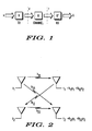
- FIG. 1 shows a high-level schematic diagram of a wireless communications channel.
- x represents user data that will be wirelessly transmitted to the receiver.
- x ⁇ represents as an estimate of the data transmitted, x.
- User data x may be split in the transmitter to produce a vector that represents multiple data streams, x 1 , x 2 ,... x N .
- User data x is processed by matrix V to produce adaptive array antenna signals z.
- Each column of matrix V is a vector containing an antenna array weight set used to transmit one of the data streams x i .
- Signals z are wirelessly transmitted from antenna elements of a transmit antenna array, and received at a receiver antenna array as received antenna signals r.
- the air interface or channel between antenna signals z and received antenna signals r includes matrix H, which describes the effects of the air ' interface or channel on signals z.
- Received antenna signals r are processed in the receiver by matrix U' to produce the estimate of data, x ⁇ .
- FIG. 2 there is depicted a two-input, two-output MIMO antenna array system, although it should be recognized that the present invention is not limited to a two antenna system, and can be applied equally well to a plurality of transmit and receive antennas.
- composite channel refers to a complete measurement or description of a channel, wherein the effects of all combinations of transmit antennas and receive antennas are considered.
- the composite channel may be thought of as the aggregation of all channels between arrays of single antennas, defined by all pair-wise combinations of transmit and receive antennas.
- h mn are complex-valued Gaussian numbers with unity average power
- E h mn ⁇ h mn * 1.
- transmitter 20 receives user data 22 and transmits the processed user data using antenna array 24, which comprises antenna elements 26.
- User data 22 enters data splitter 28, which separates the user data stream into a plurality of data streams, such as data stream 30 and data stream 32. While two data streams are shown in FIG. 3 , data splitter 28 may produce any number of data streams. Data splitter 28 splits data in proportion to control signal 34, which is produced by controller 36. For example, control signal 34 may specify a ratio of 2-to-1, wherein two bits are sent to data stream 30 and one bit is sent to data stream 32. This splitting ratio may specify an equal number of bits on both streams, or all data bits are sent to one stream.
- Data streams 30 and 32 output by data splitter 28 are input into forward error correction encoders (FEC) 38 and 40.
- FEC forward error correction encoders
- These error correction encoders may be implemented with a convolutional encoder, a turbo encoder, a block encoder, or the like.
- the type of encoding, and the rate of encoding is controlled by control signal 42, which is output by controller 36.
- control signal 42 may set error correction encoders 38 and 40 to the same error encoding schemes, or different encoding schemes.
- Modulators 44 and 46 may be implemented with linear or non-linear modulation schemes, including all varieties of modulators that modulate amplitude and phase, and combinations of amplitude and phase. Examples of modulators that may be used include Binary Phase Shift Keying modulators (BPSK), Quadrature Phase Shift Keying modulators (QPSK), M-ary phase shift keying modulators, M-ary quadrature amplitude modulators (MQAM), and the like.
- BPSK Binary Phase Shift Keying modulators
- QPSK Quadrature Phase Shift Keying modulators
- MQAM M-ary quadrature amplitude modulators
- Control signal 48 selects the type of modulation used in modulators 44 and 46. Control signal 48 is produced by controller 36. According to the present invention, the modulation schemes in the data streams may be the same, or different.
- modulators 44 and 46 are coupled to inputs of optional spreaders 49 and 50, respectively.
- Spreaders 49 and 50 spread the signal using spreading code 52, wherein the spreading code is assigned to user data 22.
- Outputs of spreaders 49 and 50 are coupled to inputs of power allocator 54.
- Power allocator 54 sets a power ratio between data streams 30 and 32 in response to control signal 56 from controller 36.
- Power allocator 54 may allocate all power to one data stream, equal powers on data streams, or other ratios of unequal power allocations.
- Power allocator 54 does not allocate power to data streams 30 and 32 relative to data streams belonging to other user data not shown in FIG. 3 . This means that power allocator 54 does not allocate an absolute level of power to a user.
- the absolute power allocated to each data stream, and each user is determined by available power in power amplifiers and other control functions not shown in FIG. 3 .
- Outputs of power allocator 54 are coupled to inputs of antenna array signal processor 58, which further processes the data streams by applying antenna array weight sets to each data stream.
- These antenna array weight sets come from controller 36 via control signal 60.
- antenna array signal processor By applying the antenna array weight sets to data streams 30 and 32, antenna array signal processor enables the transmission of each data stream with a different antenna array beamforming pattern.
- the outputs of antenna array signal processor 58 include weighted components of the input data streams.
- output 62 may include a phase-and-gain weighted portion of data stream 30 added together with a phase-and-gain weighted portion of data stream 32.
- the number of weighted outputs from antenna array signal processor 58 is equal to the number of transmit antennas. While the number of outputs of antenna array signal processor 58 may be greater than the number of data streams input, the number of data streams transmitted remains the same.
- FIG. 4 there is depicted a high-level block diagram of antenna array signal processor 58.
- data streams 30 and 32 enter antenna array signal processor 58, wherein a copy of each data stream is sent to a gain multiplier corresponding to an antenna element that will be used in an antenna array.
- a gain multiplier corresponding to an antenna element that will be used in an antenna array.
- two antennas will be used in the antenna array, therefore copies of each data stream are sent to two gain multipliers 80.
- phase shifter 82 Following each gain multiplier 80 is a phase shifter 82, which rotates the phase of the signal according to a control signal input. Outputs of phase shifters 82 are coupled to summers 84, which add the weighted data streams to produce output signals 62 and 64.
- Control signal 60 includes a plurality of antenna array weight sets, wherein one antenna array weight set is associated with each data stream.
- control signal 60 includes weight set signals 86 and 88.
- Weight set signal 86 includes gain and phase weights (i.e., complex weights) for each gain multiplier 80 and phase shifter 82 associated with data stream 30.
- the outputs of phase shifters 82 associated with data stream 30 produce antenna signals that provide a selected antenna pattern for data stream 30.
- weight set signal 88 includes phase and gain weights for each gain multiplier 80 and phase shifter 82 associated with data stream 32. In the outputs of phase shifters 82 associated with data stream 32 produce antenna signals for driving an antenna array with a selected pattern for data stream 32.
- gain multipliers 80 associated with a data stream may have different gain values and phase shifters 82 associated with a data stream may have different phase shift values, whereby producing antenna signals that work together to form a particular transmission pattern.
- output signals 62 and 64 may be up-converted, amplified, and coupled to two antenna elements 26.
- Controller 36 outputs control signals 34, 42, 48, 56, 60, and 68 based upon information received from feedback receiver 70, and data stored in memory 72.
- Feedback receiver 70 is shown coupled to antenna 74 for receiving feedback data from a remote receiver, such as the receiver shown in FIG. 5 . While antenna 74 is shown separate from antenna array 24, one of the antenna elements 26 of array 24 may be used to receive the feedback data.
- Feedback data from feedback receiver 70 may include a codebook index as described below, which may be used by controller 36 to lookup transmission parameters in the codebook 76 pre-stored within the memory 72.
- Controller 36 may also be used to calculate, or derive, additional control signals or transmission parameters based upon feedback data. Therefore, it should be understood that feedback data may include measurements upon which calculations may be based, or data that indicates parameters to be used in transmitter 20.
- receiver 98 includes antenna array 100 having elements 102 that receive radio frequency signals 104 and 106. Received RF signals 104 and 106 are most likely different signals because antenna elements 102 are spaced apart, and propagation paths taken by received RF signals 104 and 106 from antenna elements 26 of transmitter 20 are most likely different in a multi-path fading environment.
- multiple data streams are transmitted to increase the data throughput between transmitter 20 and receiver 98.
- Transmitter 20 is able to simultaneously transmit multiple data streams
- receiver 98 is able to keep the multiple streams separate by exploiting the differences in the channel characteristics between the multiple antennas at transmitter 20 and receiver 98.
- user data 22 in transmitter 20 is received by receiver 98 and output as estimated user data 108.
- Received RF signals 104 and 106 are input into radio frequency receiver front end 110, wherein the radio frequency signals are down converted and digitized.
- the output of radio frequency receiver front end 110 is a stream of complex baseband digital samples that represent received RF signals 104 and 106.
- receiver signal processor 112 which has the function of separating data streams 30 and 32 (See FIG. 3 ) in receiver 98.
- receiver signal processor 112 may be implemented by multiplying the input signals by the complex conjugate transpose of the U matrix, which is the left singular vectors of the singular value decomposition of the composite channel matrix H.
- receiver signal processor 112 may be implemented by multiplying the input signals by the pseudo-inverse of the product of the composite channel matrix H with the matrix V.
- receiver signal processor 112 may be implemented by multiplying the input signals by MMSE combining weights calculated from the product of the composite channel matrix H with the matrix V.
- Receiver signal processor 112 is controlled by control signal 115 from controller 113.
- the data streams output by receiver signal processor 112 are input to optional despreaders 114 and 116, which despread the signals using spreading code 52, which is the same spreading code used in the transmitter.
- the outputs of despreader 114 and 116 are coupled, respectively, to the inputs of demodulator and decoders 118 and 120.
- Each demodulator and decoder 118 and 120 demodulates the signal and decodes the signal using demodulation and error correction decoding techniques that complement those selected for each data stream in the transmitter.
- the type of demodulator and decoder functions used depends upon what was used in transmitter 20, as indicated by control signal 122 from controller 113.
- Demodulators and decoders 118 and 120 may be the same function, or may be different functions.
- combiner 124 The outputs from demodulator and decoder 118 and 120 are input into combiner 124, which combines the multiple streams received back into a single stream for output as estimated user data 108.
- Combiner 124 operates under the control of controller 113, as directed by control signal 126. Because the received data streams may have different data rates, and because one data stream may have a data rate equal to zero, combiner 124 must reconstruct the user data in accordance with the way data was originally split by data splitter 28 in transmitter 20 in FIG. 3 .
- receiver 98 In order to control the transmission of multiple data streams via multiple antennas at the transmitter, receiver 98 must measure the composite channel and send feedback data to the transmitter. As shown, outputs of radio frequency front end 110 are also coupled to composite channel estimator 128, which uses pilot signals transmitted from each antenna element 26 in transmitter 20 to measure the composite channel between the multiple input antennas and multiple output antennas. In practice, the receiver receives the downlink pilot data and measures the downlink channel estimates from each of the transmitter's antennas to each of its receive antennas. Although the pilots are preferably transmitted by the transmitter and used by the receiver for channel estimation, alternative channel estimation techniques, such as blind or decision-directed channel estimation methods may sometimes be used in the absence of pilots or as a supplement to the pilot-based channel estimation.
- composite channel estimator 128, which is represented by the H matrix, is input into 132 and 136.
- the SNR computer and power allocator 132 a signal-to-noise ratio is computed for each data stream hypothetically transmitted. Based upon the SNR computations, the power allocation function of block 132 allocates power to each data stream. Once power has been allocated to each data stream, final SNR calculations may be performed using the selected power allocation.
- Modulator and coder 134 receives information from SNR computer and power allocator 132 that it uses to select an encoding scheme and a modulation scheme to be used in transmitter 20. Generally, higher order modulators are selected for data streams having high signal-to-noise ratios.
- Feedback transmitter 136 receives information from 128, SNR computer and power allocator 132, and modulator and coder selector 134. This data represents calculations and selections made in receiver 98 that will be used to control the transmission modes of transmitter 20.
- feedback transmitter 136 analyzes the data and selects a codebook value (index and rank) and associated transmitter parameters that most closely match the transmitter parameters represented by the input data. Therefore, feedback transmitter 136 may include codebook 138 for producing a codebook value that is transmitted to transmitter 20 via antenna 140.
- antenna 140 is shown separate from receive antenna array 100, antenna 140 may be one of the antenna elements 102 in receive antenna array 100. Data transmitted by feedback transmitter 136 is received in transmitter 20 by feedback receiver 70.
- the present invention considers codebook-based feedback of channel information for enabling linear precoding (including beamforming) in MIMO systems, in a TDD or a FDD scenario.
- the transmitter e.g., a base station
- the receiver e.g., a mobile station
- the transmitter e.g., a base station
- the receiver has prior knowledge of a fixed, predetermined set of precoding matrices called a codebook.
- the receiver based on an estimated downlink channel, selects a particular codebook entry (a codeword) and the index of this entry is sent back to the transmitter using a low-rate feedback channel.
- the present invention provides codebooks that reduce the computational complexity necessary at the receiver for choosing a codeword.
- H ( k ) represent the M r x M t channel matrix for the k -th subcarrier in frequency.
- W represent a precoding matrix of dimension M t x M s which is an element of the codebook as defined herein (note that this W is different from the W 52 used in spreader 49and 50 and despreaders 114 and 116).
- the criteria for selecting a codeword is non-unique but usually the selection criteria involve multiplications of the form H ( k ) W .
- This present invention constructs codebooks from a restricted or finite alphabet to ease search selection complexity.
- the matrix norm is the Frobenius norm ⁇ A ⁇ F 2 means the sum of the squared magnitude of the entries of A )
- H ( k ) represents the M r x M t channel matrix for a k -th subcarrier in frequency
- K denotes the size of the cluster consisting of K adjacent subcarrier
- W is a precoding matrix of dimension M t x M s
- ⁇ ⁇ W 1 , W 2 , ...
- W N ⁇ denotes the codebook of precoding matrices
- V is the selected element from ⁇ that represents the quantized precoding matrix for the cluster.
- the present invention provides the construction of ⁇ from ⁇ and in general, from a restricted alphabet.
- d min , k min W i , W j , i ⁇ j ⁇ ⁇ W i - W j ⁇ F .
- a codebook having a larger d min, k is considered to be better than a competitor codebook.
- One embodiment of the present invention provides multi-rank (rank-independent) codebook design for arbitrary alphabets.
- the codebook has optimal distance for each rank.
- the design of codebooks with good minimum distance properties is not an exact science given the very non-linear nature of the minimum distance metric.
- a gradient-based approach can be used to iteratively design codebooks with increasing minimum distances. The first stage in this gradient-based approach is to compute rank 1 vectors with good distance properties. These rank 1 vectors will make up the first columns of the final codebook matrix design.
- the design of the rank 1 vectors is as follows:
- step 5 can be replaced by an operation that enforces the desired constraint.
- an approximate gradient for an arbitrary distance metric, d /( W 1 , W 2 ) can be calculated.
- the rank 2 through M t design can be found.
- the gradient procedure can be run multiple times from different starting points to further search for a codebook with the best minimum distance at each rank.
- different constraints can be substituted at step 7 (e.g., a constant modulus constraint or finite alphabet constraint).
- the present invention provides a multi-rank codebook designs from a reduced alphabet.
- a connection between codebook designs and the designs of mutually unbiased bases (MUBs) for quantum information theory is made.
- MUBs mutually unbiased bases
- maximal sets of MUBs are limited and can only be identified in certain dimensions which imposes restrictions on codebook sizes and dimensions. Fortunately, it appears that for most cases of practical interest it is possible to construct near-optimal codebooks from ⁇ using MUBs.
- a measure of performance for a given multi-rank codebook can be defined as follows.
- C ⁇ W 1 , W 2 , ... , W N ⁇ consisting of N elements in dimension D .
- W 1 is a D x D unitary matrix.
- W l denote by w l k the D x k sub-matrix of W l consisting of the first k columns of W l .
- the functions d 1 * , d 2 * ,.., d D * may be used to measure the performance of the codebook C for rank 1, 2,..., D respectively.
- D+1 such bases exist if D is a power of a prime.
- Specific designs for D+1 bases are known in the cases when D is a power of 2 or 3. In the particular case when D is a power of 2, it turns out that the D +1 MUBs can be constructed from the alphabet ⁇ . Details for the design of MUBs need not mentioned since codebooks can be constructed from pre-designed MUBs .
- a j represents matrix A with the columns shifted circularly to the left by j places.
- rank-1 the first columns of each of the matrices constitute a set of rank-1 codewords
- rank-2 the first two columns of each matrix constitute a set of rank-2 codewords, and so on.
- the codebook ⁇ can be extended to another codebook ⁇ of cardinality 32 (or 5-bits) by finding a set of MUBs denoted as E, F, G, H that are also composed from powers of i but differs from the set A, B, C, D by a constant rotation.
- the rotation is determined via a random search.
- codebooks can be designed from MUBs whenever the number of transmit antennas is a power of 2. Such codebooks can also be designed for other cases, but not from MUBs. Also, the codebooks mentioned here are non-unique and many such constructions are possible resulting exactly in the same performance.
- the rank-2 codebook consists of codewords which are orthogonal complements of each codeword of ⁇ . This is an example of a codebook where the rank-1 codewords are from the alphabet ⁇ while the rank-2 codewords are not. This, however, is not a constraint since the codebook search for rank-2 codewords can be equivalently formulated as a search over a codebook of rank-1 codewords (taking orthogonal complements) 1 .
- the following is a combined codebook for rank-1, rank-2 and rank-3 in the case of 3 transmit antennas and of size 8 (or 3 bits) derived from MUBs.
- the codewords are composed from a restricted alphabet ⁇ 1,x,x* ⁇ where x* denotes the conjugate of x.
- the procedure of a multi-rank codebook design from MUBs can be generalized.
- the method to design a multi-rank codebook F of size N from MUBs in a dimension D is described in the following.
- a rank r precoding matrix may be obtained from the multi-rank codebook by choosing r columns from an element of F.
- a simple codebook such as ⁇ or ⁇ are that they reduces codebook search complexity because; a) multiplications are eliminated, replaced by conjugations and negations, and b) there are only N unique columns in a codebook of size N, so the number of dot-products needed to be computed for searching over rank-1 matrices is the same as that for rank-2 or higher ranked matrices.
- a simple codebook results in equal-power transmission from all antennas, reduces storage because a single codebook is common for matrices of all ranks, and provides link performance which is near-optimal compared to the best known codebooks constructed from unconstrained alphabet.
- the present invention provides a multi-rank codebook design using householder transformation and where the entries are from a finite alphabet (e.g., powers of i ).
- codebooks are designed with good distance properties for multiple ranks using a Householder transform approach.
- the Householder transform converts a vector into a matrix and the columns of the matrix can be used to design matrix codebooks.
- an example codebook is shown with two 4x4 codewords (matrices).
- the first column of each codeword comprises the set of rank-1 codewords which have been designed with good rank-1 distances as detailed above.
- the entire matrix of each codeword comprises the set of rank-2 codewords which have been designed with good rank-2 distances as detailed above.
- the determination of good distances first includes determining the minimum distance between rank pairs, and secondly includes determining the maximum of those minimums.
- the prior art provided rank-dependent codebooks wherein the distance determined for a set of rank-1 codewords is maximized for the rank-1 codewords or the distance determined for a set of rank-2 codewords is maximized for the rank-2 codewords.
- the present invention provides a rank-independent codebook wherein the distance determined for a set of rank-1 codewords and the distance determined for a set of rank-2 codewords are maximized jointly.
- the rank-1 results are used determine the rank-2 results, then rank-1 and rank-2 results are used to determine the rank-3 results, etc.
- lower rank codewords are subsets of higher rank codewords, e.g. the rank-1 codeword vector is the first column of the rank-2 codeword matrix, as shown in FIG. 6 .
- the mobile just needs to determine which of the codebook weights to use for each stream.
- Various power, beamforming, and/or capacity criteria can be used to determine the weights such as are known in the art.
- An index of the selected pre-coded set of weights is then sent back to the base station, whereupon the base station checks that index against the codebook stored in memory to select the indicated set of weights in subsequent transmissions.
- the base station uses the first n columns of selected matrices as the beamforming weights
- FIG. 7 shows throughput results comparing the various codebooks. The results show that the low complexity rank-independent codebooks have very similar throughput performance as the other codebooks.
- FIG. 8 shows the throughput gain (as a function of SNR) of the rank-independent non-constant modulus codebook over the other methods. As expected there is no gain at high SNRs since the rank dependent codebooks were designed with optimal rank 2 distance (and the rank-independent codebooks had excellent rank 2 distance as well). However, at low SNRs, the rank-independent codebooks have a performance gain since these codebooks are designed to have a good rank 1 distance as well as a good rank 2 distance.
- the present invention also provides a method for providing feedback for closed-loop transmitting with multiple transmit antennas and multiple receive antennas.
- the method includes a first step 900 of providing a codebook containing sets of weightings for each data stream of the multiple transmit antennas with each set of weightings identified by an index known to a transmitter and a receiver.
- Each set of weightings comprises a vector or matrix codeword for each transmission rank (i.e. number of data streams).
- the same codebook is utilized for any number of data streams up to the number of transmit antennas (i.e. is rank independent), and resides in both the transmitter and receiver with agreed upon indexes for each codeword.
- a novel aspect of the present invention is providing a codebook that only includes entries that utilize a finite alphabet consisting of powers of i where i equals the square root of -1. Yet another novel aspect is providing a codebook with optimal distance for each rank.
- Another novel aspect of the present invention is having portions of lower ranked sets of weightings used as subsets of higher ranked sets of weightings in the codebook.
- portions of lower ranked sets of weightings are used as subsets of higher ranked sets of weightings in the codebook.
- a column or row of a rank 1 codeword vector is used as a subset of a rank 2 codeword matrix (for example the first column of the rank 2 codeword matrix is the rank 1 codeword vector), and wherein the number of columns or rows is equal to the transmission rank.
- This sharing of entries reduces computational complexity.
- the matrix from a second codebook is determined from a vector in the first codebook associated with the codebook index using a Householder transformation.
- a next step 902 includes measuring a composite channel between the transmitter and receiver by the receiver using a channel estimator known in the art.
- a next step 904 includes determining a performance metric for each set of weightings of the codebook by the receiver.
- the performance metric can include quality and capacity characteristics as are known in the art, including interference, SNR, data rate, and the like.
- this step includes calculating a rank 1 performance metric of a set of rank 1 weightings, and calculating a rank 2 performance metric of a set of rank 2 weightings, wherein a subset of the rank 2 weightings include the set of rank 1 weightings.
- the codebook is designed with entries that are powers of i (or scaled powers of i) as in the preferred embodiment of the present invention, then the calculation of the performance metrics for all ranks may be done with no multiplications.
- a next step 906 includes selecting a preferred set of weightings for each data stream in response to the performance metrics by the receiver.
- This step includes deciding the rank of the transmission based on the rank 1 and rank 2 performance metrics, and selecting the index of the set of weightings of the decided rank (i.e. selecting the index of the codeword of the decided rank).
- the deciding substep includes choosing the rank with the best performance metrics.
- the performance metric can be the quality and capacity characteristics as are known in the art, including interference, SNR, data rate, and the like.
- the rank 2 performance metric is a link capacity
- the rank 1 performance metric is a received signal-to-noise ratio (SNR).
- a next step 908 includes feeding back an index of the preferred set of weightings by the receiver to the transmitter for use in subsequent transmissions of each data stream from the transmitter.
- a preferred transmit beamforming codeword for a selected index of a particular transmission rank is contained in each transmit beamforming codeword of greater rank.
- the invention can be implemented in any suitable form including hardware, software, firmware or any combination of these.
- the invention may optionally be implemented partly as computer software running on one or more data processors and/or digital signal processors.
- the elements and components of an embodiment of the invention may be physically, functionally and logically implemented in any suitable way. Indeed the functionality may be implemented in a single unit, in a plurality of units or as part of other functional units. As such, the invention may be implemented in a single unit or may be physically and functionally distributed between different units and processors.
Landscapes
- Engineering & Computer Science (AREA)
- Computer Networks & Wireless Communication (AREA)
- Signal Processing (AREA)
- Physics & Mathematics (AREA)
- Mathematical Physics (AREA)
- Radio Transmission System (AREA)
- Mobile Radio Communication Systems (AREA)
Applications Claiming Priority (3)
| Application Number | Priority Date | Filing Date | Title |
|---|---|---|---|
| US93822007P | 2007-05-16 | 2007-05-16 | |
| US12/060,301 US8107544B2 (en) | 2007-05-16 | 2008-04-01 | Method and apparatus for feedback in closed loop transmitting |
| PCT/US2008/062211 WO2008144189A2 (en) | 2007-05-16 | 2008-05-01 | Method and apparatus for feedback in closed loop transmitting |
Publications (2)
| Publication Number | Publication Date |
|---|---|
| EP2158694A2 EP2158694A2 (en) | 2010-03-03 |
| EP2158694B1 true EP2158694B1 (en) | 2013-01-02 |
Family
ID=40027460
Family Applications (1)
| Application Number | Title | Priority Date | Filing Date |
|---|---|---|---|
| EP08747338A Active EP2158694B1 (en) | 2007-05-16 | 2008-05-01 | Method and apparatus for feedback in closed loop transmitting |
Country Status (6)
| Country | Link |
|---|---|
| US (2) | US8107544B2 (zh) |
| EP (1) | EP2158694B1 (zh) |
| JP (1) | JP2010527562A (zh) |
| CN (1) | CN101682379B (zh) |
| TW (1) | TWI436609B (zh) |
| WO (1) | WO2008144189A2 (zh) |
Families Citing this family (50)
| Publication number | Priority date | Publication date | Assignee | Title |
|---|---|---|---|---|
| IT1403065B1 (it) * | 2010-12-01 | 2013-10-04 | Andrew Wireless Systems Gmbh | Distributed antenna system for mimo signals. |
| KR101454027B1 (ko) * | 2007-08-10 | 2014-10-24 | 한국전자통신연구원 | 병렬 구조를 가지는 시분할 다중화 통신 시스템 및 방법 |
| KR101421592B1 (ko) * | 2007-09-05 | 2014-08-14 | 삼성전자주식회사 | 인터리버 분할 다중 접속 시스템에서 송수신 장치 및 방법 |
| KR101372736B1 (ko) * | 2007-09-28 | 2014-03-26 | 삼성전자주식회사 | 통신 시스템에서 피드백 정보 송신 장치 및 방법 |
| CN101471707B (zh) * | 2007-12-28 | 2013-09-11 | 华为技术有限公司 | 时分双工多输入多输出的下行波束形成方法、装置和系统 |
| US8165595B2 (en) * | 2008-01-25 | 2012-04-24 | Samsung Electronics Co., Ltd. | System and method for multi-stage antenna training of beamforming vectors |
| US8280445B2 (en) | 2008-02-13 | 2012-10-02 | Samsung Electronics Co., Ltd. | System and method for antenna training of beamforming vectors by selective use of beam level training |
| KR101646759B1 (ko) | 2008-02-28 | 2016-08-08 | 애플 인크. | 무선 통신 시그널링에 적용되는 코딩을 식별하는 정보를 포함하는 피드백 데이터 구조체의 통신 |
| EP2277300A4 (en) * | 2008-04-29 | 2013-05-22 | Apple Inc | IMPROVING THE PERFORMANCE OF A CELLULAR NETWORK WITH MULTI-ANTENNA BEAM FORMATION |
| KR101521883B1 (ko) * | 2008-04-30 | 2015-05-20 | 삼성전자주식회사 | 코드북 기반 폐루프 다중 안테나 시스템에서 송수신 장치및 방법 |
| US8199836B2 (en) * | 2008-05-02 | 2012-06-12 | Nec Laboratories America, Inc. | Multi-resolution precoding codebook |
| US8149946B2 (en) * | 2008-05-06 | 2012-04-03 | Industrial Technology Research Institute | Joint transceiver design for MIMO communications |
| US8958408B1 (en) * | 2008-06-05 | 2015-02-17 | The Boeing Company | Coded aperture scanning |
| US8555145B2 (en) * | 2008-09-04 | 2013-10-08 | Apple Inc. | Systems and methods of encoding using a reduced codebook with adaptive resetting |
| US8351544B2 (en) * | 2008-12-15 | 2013-01-08 | Motorola Mobility Llc | Method and apparatus for codebook-based feedback in a closed loop wireless communication system |
| KR101707680B1 (ko) * | 2008-12-21 | 2017-02-17 | 엘지전자 주식회사 | 무선 통신 시스템에서 정보 전송 장치 및 방법 |
| US8743985B2 (en) * | 2009-01-05 | 2014-06-03 | Intel Corporation | Method and apparatus using a base codebook structure for beamforming |
| US8457026B1 (en) * | 2009-02-03 | 2013-06-04 | Sibeam, Inc. | Enhanced wireless data rates using multiple beams |
| WO2010105415A1 (en) * | 2009-03-17 | 2010-09-23 | Huawei Technologies Co., Ltd. | Method for generating a codebook |
| US20100260234A1 (en) * | 2009-04-09 | 2010-10-14 | Motorola, Inc. | Closed-loop transmission feedback in wireless communication systems |
| EP3197066A1 (en) * | 2009-08-14 | 2017-07-26 | Telefonaktiebolaget LM Ericsson (publ) | Antenna device |
| CN101997654B (zh) | 2009-08-17 | 2013-08-28 | 富士通株式会社 | 生成预编码矩阵码书组的方法和装置 |
| WO2011021861A2 (en) * | 2009-08-19 | 2011-02-24 | Lg Electronics Inc. | Apparatus and method for generating codebook in wireless communication system |
| JP5701299B2 (ja) * | 2009-09-02 | 2015-04-15 | アップル インコーポレイテッド | コードワードのインデックスを送信する方法及び装置 |
| CN102088340B (zh) * | 2010-01-11 | 2013-04-17 | 电信科学技术研究院 | 一种多天线系统发送、接收信息的方法及装置 |
| US9148205B2 (en) | 2010-01-25 | 2015-09-29 | Qualcomm Incorporated | Feedback for supporting SU-MIMO and MU-MIMO operation in wireless communication |
| JP5275280B2 (ja) * | 2010-03-29 | 2013-08-28 | 株式会社エヌ・ティ・ティ・ドコモ | コードブック生成方法 |
| GB2479377B (en) | 2010-04-07 | 2013-08-14 | Toshiba Res Europ Ltd | Dual indicator scheme for channel state information feedback |
| US9571173B2 (en) * | 2010-08-16 | 2017-02-14 | Qualcomm Incorporated | Enforcing constant modulus and finite alphabet properties in adaptive and dual-stage codebooks |
| MX2013000954A (es) | 2010-12-10 | 2013-03-22 | Panasonic Corp | Metodo de generacion de señales y aparato de generacion de señales. |
| US8942147B2 (en) | 2011-01-11 | 2015-01-27 | Yibo Jiang | Closed loop transmit diversity in continuous packet connectivity |
| KR102133354B1 (ko) | 2011-02-18 | 2020-07-13 | 선 페이턴트 트러스트 | 신호생성방법 및 신호생성장치 |
| US9294165B2 (en) | 2011-04-19 | 2016-03-22 | Panasonic Intellectual Property Corporation Of America | Signal generating method and signal generating device |
| US20120328031A1 (en) * | 2011-06-24 | 2012-12-27 | Nokia Siemens Networks Oy | Codebooks for Mobile Communications |
| CN102857285B (zh) * | 2011-06-30 | 2017-11-03 | 中兴通讯股份有限公司 | 信道信息反馈方法及装置 |
| US8797966B2 (en) | 2011-09-23 | 2014-08-05 | Ofinno Technologies, Llc | Channel state information transmission |
| EP2761772A4 (en) * | 2011-09-30 | 2015-05-13 | Intel Corp | MU-MIMO RADIO CONNECTIONS WITH IMPROVED PERFORMANCE |
| US8885569B2 (en) | 2011-12-19 | 2014-11-11 | Ofinno Technologies, Llc | Beamforming signaling in a wireless network |
| CN103220080B (zh) * | 2012-01-18 | 2016-01-20 | 上海贝尔股份有限公司 | 用于量化信道状态信息的方法与装置 |
| CN103220090B (zh) * | 2012-01-19 | 2017-03-22 | 中国移动通信集团公司 | 码本反馈方法及信号接收装置、信号发送方法及装置 |
| CN103782533B (zh) * | 2012-07-02 | 2017-02-22 | 华为技术有限公司 | 确定预编码矩阵指示的方法、用户设备和基站 |
| EP4228166A1 (en) * | 2012-09-28 | 2023-08-16 | InterDigital Patent Holdings, Inc. | Method for wifi beamforming, feedback, and sounding (wibeam) |
| US9020061B2 (en) * | 2013-02-22 | 2015-04-28 | Nec Laboratories America, Inc. | Codebook construction |
| US9755716B2 (en) | 2013-03-07 | 2017-09-05 | Nec Corporation | Codebook construction |
| CN104135314B (zh) | 2013-04-30 | 2018-04-27 | 上海诺基亚贝尔股份有限公司 | Mimo系统中的多天线信道码本反馈方法及装置 |
| CN105099604B (zh) * | 2014-05-07 | 2018-11-20 | 中兴通讯股份有限公司 | 信道状态反馈信息反馈方法、终端、基站及通信系统 |
| US9874626B2 (en) * | 2014-12-15 | 2018-01-23 | The Boeing Company | Multicode transmitter |
| CN107359918A (zh) * | 2016-05-10 | 2017-11-17 | 北京信威通信技术股份有限公司 | 一种生成预编码码本的方法和系统 |
| US10707939B2 (en) * | 2017-10-03 | 2020-07-07 | Mediatek Inc. | Codebook-based uplink transmission in wireless communications |
| US10965352B1 (en) * | 2019-09-24 | 2021-03-30 | Rampart Communications, Inc. | Communication system and methods using very large multiple-in multiple-out (MIMO) antenna systems with extremely large class of fast unitary transformations |
Family Cites Families (14)
| Publication number | Priority date | Publication date | Assignee | Title |
|---|---|---|---|---|
| US6859503B2 (en) | 2001-04-07 | 2005-02-22 | Motorola, Inc. | Method and system in a transceiver for controlling a multiple-input, multiple-output communications channel |
| US6927728B2 (en) | 2003-03-13 | 2005-08-09 | Motorola, Inc. | Method and apparatus for multi-antenna transmission |
| US7362822B2 (en) | 2004-09-08 | 2008-04-22 | Intel Corporation | Recursive reduction of channel state feedback |
| US7139328B2 (en) | 2004-11-04 | 2006-11-21 | Motorola, Inc. | Method and apparatus for closed loop data transmission |
| CN100550686C (zh) * | 2005-03-24 | 2009-10-14 | 中国科学技术大学 | 一种接收机辅助的波束成型方法 |
| KR101124932B1 (ko) | 2005-05-30 | 2012-03-28 | 삼성전자주식회사 | 어레이 안테나를 이용하는 이동 통신 시스템에서의 데이터송/수신 장치 및 방법 |
| US7428269B2 (en) * | 2005-06-01 | 2008-09-23 | Qualcomm Incorporated | CQI and rank prediction for list sphere decoding and ML MIMO receivers |
| US7917176B2 (en) * | 2006-02-14 | 2011-03-29 | Nec Laboratories America, Inc. | Structured codebook and successive beamforming for multiple-antenna systems |
| EP2086140B1 (en) * | 2006-11-22 | 2016-03-09 | Fujitsu Limited | Mimo-ofdm communication system and mimo-ofdm communication method |
| US8073069B2 (en) * | 2007-01-05 | 2011-12-06 | Apple Inc. | Multi-user MIMO-SDMA for finite rate feedback systems |
| US7995671B2 (en) * | 2007-02-09 | 2011-08-09 | Qualcomm Incorporated | Multiple-input multiple-output (MIMO) transmission with rank-dependent precoding |
| US7809074B2 (en) * | 2007-03-16 | 2010-10-05 | Freescale Semiconductor, Inc. | Generalized reference signaling scheme for multi-user, multiple input, multiple output (MU-MIMO) using arbitrarily precoded reference signals |
| US8135083B2 (en) * | 2007-05-01 | 2012-03-13 | Nec Laboratories America, Inc. | Codebook method for a multiple input multiple output wireless system |
| US8184732B2 (en) * | 2007-05-01 | 2012-05-22 | Broadcom Corporation | Method and system for codebook design for pre-coding techniques |
-
2008
- 2008-04-01 US US12/060,301 patent/US8107544B2/en not_active Expired - Fee Related
- 2008-05-01 JP JP2010508488A patent/JP2010527562A/ja active Pending
- 2008-05-01 WO PCT/US2008/062211 patent/WO2008144189A2/en active Application Filing
- 2008-05-01 EP EP08747338A patent/EP2158694B1/en active Active
- 2008-05-01 CN CN200880016233.3A patent/CN101682379B/zh active Active
- 2008-05-16 TW TW097118216A patent/TWI436609B/zh not_active IP Right Cessation
-
2011
- 2011-11-22 US US13/301,953 patent/US8406328B2/en active Active
Also Published As
| Publication number | Publication date |
|---|---|
| TW200915756A (en) | 2009-04-01 |
| CN101682379A (zh) | 2010-03-24 |
| TWI436609B (zh) | 2014-05-01 |
| WO2008144189A2 (en) | 2008-11-27 |
| CN101682379B (zh) | 2012-11-07 |
| EP2158694A2 (en) | 2010-03-03 |
| WO2008144189A4 (en) | 2009-03-12 |
| US8406328B2 (en) | 2013-03-26 |
| WO2008144189A3 (en) | 2009-01-22 |
| JP2010527562A (ja) | 2010-08-12 |
| US20120069925A1 (en) | 2012-03-22 |
| US20080285667A1 (en) | 2008-11-20 |
| US8107544B2 (en) | 2012-01-31 |
Similar Documents
| Publication | Publication Date | Title |
|---|---|---|
| EP2158694B1 (en) | Method and apparatus for feedback in closed loop transmitting | |
| US8750419B2 (en) | Method and apparatus for codebook based feedback in a closed loop wireless communication system | |
| US8325843B2 (en) | MIMO codebook generation | |
| US6859503B2 (en) | Method and system in a transceiver for controlling a multiple-input, multiple-output communications channel | |
| CN101682453B (zh) | 用于开环su mimo的cdd预编码 | |
| CN101512929B (zh) | 用于在mimo无线通信系统中提供有效预编码反馈的方法和设备 | |
| CN107070512B (zh) | 使用块对角矩阵进行预编码的方法 | |
| US9054754B2 (en) | Method and apparatus for acquiring a precoding matrix indicator and a precoding matrix | |
| US8711970B2 (en) | Precoding codebooks for MIMO communication systems | |
| CN100382458C (zh) | 使用多发射多接收天线阵列的无线通信 | |
| EP2250848B1 (en) | Progressive feedback for high resolution limited feedback wireless communication | |
| US7813458B2 (en) | System and method for precoding in a multiple-input multiple-output (MIMO) system | |
| US8325839B2 (en) | Simple MIMO precoding codebook design for a MIMO wireless communications system | |
| KR101356508B1 (ko) | 무선 통신 시스템에서의 데이터 전송 방법 | |
| US20060013250A1 (en) | Unified MIMO transmission and reception | |
| CN102349243B (zh) | 在多天线系统中发射信号的方法和用户设备 | |
| US8537921B2 (en) | Apparatuses and methods for transmission and reception in a codebook based closed-loop (CL)-multiple input multiple output (MIMO) system | |
| US8494088B2 (en) | Transmitting/receiving apparatus and method thereof in codebook based multiple antenna system | |
| CN108183737B (zh) | 用于mimo下行系统中基于黄金码的传输与解码方法 | |
| KR101599532B1 (ko) | Mimo 코드북 생성 방법 및 장치 | |
| Salim et al. | Hybrid pilot/quantization based feedback in multi-antenna TDD systems |
Legal Events
| Date | Code | Title | Description |
|---|---|---|---|
| PUAI | Public reference made under article 153(3) epc to a published international application that has entered the european phase |
Free format text: ORIGINAL CODE: 0009012 |
|
| 17P | Request for examination filed |
Effective date: 20091216 |
|
| AK | Designated contracting states |
Kind code of ref document: A2 Designated state(s): AT BE BG CH CY CZ DE DK EE ES FI FR GB GR HR HU IE IS IT LI LT LU LV MC MT NL NO PL PT RO SE SI SK TR |
|
| AX | Request for extension of the european patent |
Extension state: AL BA MK RS |
|
| 17Q | First examination report despatched |
Effective date: 20100311 |
|
| RAP1 | Party data changed (applicant data changed or rights of an application transferred) |
Owner name: MOTOROLA MOBILITY, INC. |
|
| DAX | Request for extension of the european patent (deleted) | ||
| RAP1 | Party data changed (applicant data changed or rights of an application transferred) |
Owner name: MOTOROLA MOBILITY LLC |
|
| GRAP | Despatch of communication of intention to grant a patent |
Free format text: ORIGINAL CODE: EPIDOSNIGR1 |
|
| GRAS | Grant fee paid |
Free format text: ORIGINAL CODE: EPIDOSNIGR3 |
|
| GRAA | (expected) grant |
Free format text: ORIGINAL CODE: 0009210 |
|
| AK | Designated contracting states |
Kind code of ref document: B1 Designated state(s): AT BE BG CH CY CZ DE DK EE ES FI FR GB GR HR HU IE IS IT LI LT LU LV MC MT NL NO PL PT RO SE SI SK TR |
|
| REG | Reference to a national code |
Ref country code: GB Ref legal event code: FG4D |
|
| REG | Reference to a national code |
Ref country code: AT Ref legal event code: REF Ref document number: 592092 Country of ref document: AT Kind code of ref document: T Effective date: 20130115 Ref country code: CH Ref legal event code: EP |
|
| REG | Reference to a national code |
Ref country code: IE Ref legal event code: FG4D |
|
| REG | Reference to a national code |
Ref country code: NL Ref legal event code: T3 |
|
| REG | Reference to a national code |
Ref country code: DE Ref legal event code: R096 Ref document number: 602008021366 Country of ref document: DE Effective date: 20130228 |
|
| REG | Reference to a national code |
Ref country code: AT Ref legal event code: MK05 Ref document number: 592092 Country of ref document: AT Kind code of ref document: T Effective date: 20130102 |
|
| PG25 | Lapsed in a contracting state [announced via postgrant information from national office to epo] |
Ref country code: SI Free format text: LAPSE BECAUSE OF FAILURE TO SUBMIT A TRANSLATION OF THE DESCRIPTION OR TO PAY THE FEE WITHIN THE PRESCRIBED TIME-LIMIT Effective date: 20130102 |
|
| REG | Reference to a national code |
Ref country code: LT Ref legal event code: MG4D |
|
| PG25 | Lapsed in a contracting state [announced via postgrant information from national office to epo] |
Ref country code: IS Free format text: LAPSE BECAUSE OF FAILURE TO SUBMIT A TRANSLATION OF THE DESCRIPTION OR TO PAY THE FEE WITHIN THE PRESCRIBED TIME-LIMIT Effective date: 20130502 Ref country code: AT Free format text: LAPSE BECAUSE OF FAILURE TO SUBMIT A TRANSLATION OF THE DESCRIPTION OR TO PAY THE FEE WITHIN THE PRESCRIBED TIME-LIMIT Effective date: 20130102 Ref country code: BG Free format text: LAPSE BECAUSE OF FAILURE TO SUBMIT A TRANSLATION OF THE DESCRIPTION OR TO PAY THE FEE WITHIN THE PRESCRIBED TIME-LIMIT Effective date: 20130402 Ref country code: BE Free format text: LAPSE BECAUSE OF FAILURE TO SUBMIT A TRANSLATION OF THE DESCRIPTION OR TO PAY THE FEE WITHIN THE PRESCRIBED TIME-LIMIT Effective date: 20130102 Ref country code: LT Free format text: LAPSE BECAUSE OF FAILURE TO SUBMIT A TRANSLATION OF THE DESCRIPTION OR TO PAY THE FEE WITHIN THE PRESCRIBED TIME-LIMIT Effective date: 20130102 Ref country code: ES Free format text: LAPSE BECAUSE OF FAILURE TO SUBMIT A TRANSLATION OF THE DESCRIPTION OR TO PAY THE FEE WITHIN THE PRESCRIBED TIME-LIMIT Effective date: 20130413 Ref country code: NO Free format text: LAPSE BECAUSE OF FAILURE TO SUBMIT A TRANSLATION OF THE DESCRIPTION OR TO PAY THE FEE WITHIN THE PRESCRIBED TIME-LIMIT Effective date: 20130402 Ref country code: CZ Free format text: LAPSE BECAUSE OF FAILURE TO SUBMIT A TRANSLATION OF THE DESCRIPTION OR TO PAY THE FEE WITHIN THE PRESCRIBED TIME-LIMIT Effective date: 20130102 Ref country code: SE Free format text: LAPSE BECAUSE OF FAILURE TO SUBMIT A TRANSLATION OF THE DESCRIPTION OR TO PAY THE FEE WITHIN THE PRESCRIBED TIME-LIMIT Effective date: 20130102 |
|
| PG25 | Lapsed in a contracting state [announced via postgrant information from national office to epo] |
Ref country code: PT Free format text: LAPSE BECAUSE OF FAILURE TO SUBMIT A TRANSLATION OF THE DESCRIPTION OR TO PAY THE FEE WITHIN THE PRESCRIBED TIME-LIMIT Effective date: 20130502 Ref country code: LV Free format text: LAPSE BECAUSE OF FAILURE TO SUBMIT A TRANSLATION OF THE DESCRIPTION OR TO PAY THE FEE WITHIN THE PRESCRIBED TIME-LIMIT Effective date: 20130102 Ref country code: GR Free format text: LAPSE BECAUSE OF FAILURE TO SUBMIT A TRANSLATION OF THE DESCRIPTION OR TO PAY THE FEE WITHIN THE PRESCRIBED TIME-LIMIT Effective date: 20130403 Ref country code: FI Free format text: LAPSE BECAUSE OF FAILURE TO SUBMIT A TRANSLATION OF THE DESCRIPTION OR TO PAY THE FEE WITHIN THE PRESCRIBED TIME-LIMIT Effective date: 20130102 Ref country code: PL Free format text: LAPSE BECAUSE OF FAILURE TO SUBMIT A TRANSLATION OF THE DESCRIPTION OR TO PAY THE FEE WITHIN THE PRESCRIBED TIME-LIMIT Effective date: 20130102 |
|
| PG25 | Lapsed in a contracting state [announced via postgrant information from national office to epo] |
Ref country code: HR Free format text: LAPSE BECAUSE OF FAILURE TO SUBMIT A TRANSLATION OF THE DESCRIPTION OR TO PAY THE FEE WITHIN THE PRESCRIBED TIME-LIMIT Effective date: 20130102 |
|
| PG25 | Lapsed in a contracting state [announced via postgrant information from national office to epo] |
Ref country code: SK Free format text: LAPSE BECAUSE OF FAILURE TO SUBMIT A TRANSLATION OF THE DESCRIPTION OR TO PAY THE FEE WITHIN THE PRESCRIBED TIME-LIMIT Effective date: 20130102 Ref country code: RO Free format text: LAPSE BECAUSE OF FAILURE TO SUBMIT A TRANSLATION OF THE DESCRIPTION OR TO PAY THE FEE WITHIN THE PRESCRIBED TIME-LIMIT Effective date: 20130102 Ref country code: DK Free format text: LAPSE BECAUSE OF FAILURE TO SUBMIT A TRANSLATION OF THE DESCRIPTION OR TO PAY THE FEE WITHIN THE PRESCRIBED TIME-LIMIT Effective date: 20130102 Ref country code: EE Free format text: LAPSE BECAUSE OF FAILURE TO SUBMIT A TRANSLATION OF THE DESCRIPTION OR TO PAY THE FEE WITHIN THE PRESCRIBED TIME-LIMIT Effective date: 20130102 |
|
| PLBE | No opposition filed within time limit |
Free format text: ORIGINAL CODE: 0009261 |
|
| STAA | Information on the status of an ep patent application or granted ep patent |
Free format text: STATUS: NO OPPOSITION FILED WITHIN TIME LIMIT |
|
| PG25 | Lapsed in a contracting state [announced via postgrant information from national office to epo] |
Ref country code: CY Free format text: LAPSE BECAUSE OF FAILURE TO SUBMIT A TRANSLATION OF THE DESCRIPTION OR TO PAY THE FEE WITHIN THE PRESCRIBED TIME-LIMIT Effective date: 20130102 |
|
| 26N | No opposition filed |
Effective date: 20131003 |
|
| PG25 | Lapsed in a contracting state [announced via postgrant information from national office to epo] |
Ref country code: IT Free format text: LAPSE BECAUSE OF FAILURE TO SUBMIT A TRANSLATION OF THE DESCRIPTION OR TO PAY THE FEE WITHIN THE PRESCRIBED TIME-LIMIT Effective date: 20130102 Ref country code: MC Free format text: LAPSE BECAUSE OF FAILURE TO SUBMIT A TRANSLATION OF THE DESCRIPTION OR TO PAY THE FEE WITHIN THE PRESCRIBED TIME-LIMIT Effective date: 20130102 |
|
| REG | Reference to a national code |
Ref country code: CH Ref legal event code: PL |
|
| REG | Reference to a national code |
Ref country code: DE Ref legal event code: R097 Ref document number: 602008021366 Country of ref document: DE Effective date: 20131003 |
|
| PG25 | Lapsed in a contracting state [announced via postgrant information from national office to epo] |
Ref country code: CH Free format text: LAPSE BECAUSE OF NON-PAYMENT OF DUE FEES Effective date: 20130531 Ref country code: LI Free format text: LAPSE BECAUSE OF NON-PAYMENT OF DUE FEES Effective date: 20130531 |
|
| REG | Reference to a national code |
Ref country code: IE Ref legal event code: MM4A |
|
| PG25 | Lapsed in a contracting state [announced via postgrant information from national office to epo] |
Ref country code: IE Free format text: LAPSE BECAUSE OF NON-PAYMENT OF DUE FEES Effective date: 20130501 |
|
| PG25 | Lapsed in a contracting state [announced via postgrant information from national office to epo] |
Ref country code: MT Free format text: LAPSE BECAUSE OF FAILURE TO SUBMIT A TRANSLATION OF THE DESCRIPTION OR TO PAY THE FEE WITHIN THE PRESCRIBED TIME-LIMIT Effective date: 20130102 |
|
| PG25 | Lapsed in a contracting state [announced via postgrant information from national office to epo] |
Ref country code: TR Free format text: LAPSE BECAUSE OF FAILURE TO SUBMIT A TRANSLATION OF THE DESCRIPTION OR TO PAY THE FEE WITHIN THE PRESCRIBED TIME-LIMIT Effective date: 20130102 |
|
| PG25 | Lapsed in a contracting state [announced via postgrant information from national office to epo] |
Ref country code: LU Free format text: LAPSE BECAUSE OF NON-PAYMENT OF DUE FEES Effective date: 20130501 Ref country code: HU Free format text: LAPSE BECAUSE OF FAILURE TO SUBMIT A TRANSLATION OF THE DESCRIPTION OR TO PAY THE FEE WITHIN THE PRESCRIBED TIME-LIMIT; INVALID AB INITIO Effective date: 20080501 |
|
| REG | Reference to a national code |
Ref country code: DE Ref legal event code: R082 Ref document number: 602008021366 Country of ref document: DE Representative=s name: KASTEL PATENTANWAELTE, DE Ref country code: DE Ref legal event code: R082 Ref document number: 602008021366 Country of ref document: DE Representative=s name: BETTEN & RESCH PATENT- UND RECHTSANWAELTE PART, DE |
|
| REG | Reference to a national code |
Ref country code: FR Ref legal event code: PLFP Year of fee payment: 9 |
|
| REG | Reference to a national code |
Ref country code: FR Ref legal event code: PLFP Year of fee payment: 10 |
|
| REG | Reference to a national code |
Ref country code: NL Ref legal event code: PD Owner name: GOOGLE TECHNOLOGY HOLDINGS LLC; US Free format text: DETAILS ASSIGNMENT: CHANGE OF OWNER(S), ASSIGNMENT; FORMER OWNER NAME: MOTOROLA MOBILITY LLC Effective date: 20170626 |
|
| REG | Reference to a national code |
Ref country code: GB Ref legal event code: 732E Free format text: REGISTERED BETWEEN 20170831 AND 20170906 |
|
| REG | Reference to a national code |
Ref country code: FR Ref legal event code: TP Owner name: GOOGLE TECHNOLOGY HOLDINGS LLC, US Effective date: 20171214 |
|
| REG | Reference to a national code |
Ref country code: FR Ref legal event code: PLFP Year of fee payment: 11 |
|
| REG | Reference to a national code |
Ref country code: DE Ref legal event code: R082 Ref document number: 602008021366 Country of ref document: DE Representative=s name: BETTEN & RESCH PATENT- UND RECHTSANWAELTE PART, DE Ref country code: DE Ref legal event code: R081 Ref document number: 602008021366 Country of ref document: DE Owner name: GOOGLE TECHNOLOGY HOLDINGS LLC, MOUNTAIN VIEW, US Free format text: FORMER OWNER: MOTOROLA MOBILITY LLC, LIBERTYVILLE, ILL., US |
|
| PGFP | Annual fee paid to national office [announced via postgrant information from national office to epo] |
Ref country code: NL Payment date: 20200526 Year of fee payment: 13 Ref country code: FR Payment date: 20200525 Year of fee payment: 13 |
|
| REG | Reference to a national code |
Ref country code: NL Ref legal event code: MM Effective date: 20210601 |
|
| PG25 | Lapsed in a contracting state [announced via postgrant information from national office to epo] |
Ref country code: NL Free format text: LAPSE BECAUSE OF NON-PAYMENT OF DUE FEES Effective date: 20210601 Ref country code: FR Free format text: LAPSE BECAUSE OF NON-PAYMENT OF DUE FEES Effective date: 20210531 |
|
| P01 | Opt-out of the competence of the unified patent court (upc) registered |
Effective date: 20230512 |
|
| PGFP | Annual fee paid to national office [announced via postgrant information from national office to epo] |
Ref country code: DE Payment date: 20230530 Year of fee payment: 16 |
|
| PGFP | Annual fee paid to national office [announced via postgrant information from national office to epo] |
Ref country code: GB Payment date: 20230529 Year of fee payment: 16 |