EP2158431B1 - Reinforcement device, lighting device socket, lighting device assembly and vehicle - Google Patents
Reinforcement device, lighting device socket, lighting device assembly and vehicle Download PDFInfo
- Publication number
- EP2158431B1 EP2158431B1 EP20080763157 EP08763157A EP2158431B1 EP 2158431 B1 EP2158431 B1 EP 2158431B1 EP 20080763157 EP20080763157 EP 20080763157 EP 08763157 A EP08763157 A EP 08763157A EP 2158431 B1 EP2158431 B1 EP 2158431B1
- Authority
- EP
- European Patent Office
- Prior art keywords
- lighting device
- socket
- catch
- ring
- reinforcement
- Prior art date
- Legal status (The legal status is an assumption and is not a legal conclusion. Google has not performed a legal analysis and makes no representation as to the accuracy of the status listed.)
- Active
Links
Images


Classifications
-
- F—MECHANICAL ENGINEERING; LIGHTING; HEATING; WEAPONS; BLASTING
- F21—LIGHTING
- F21V—FUNCTIONAL FEATURES OR DETAILS OF LIGHTING DEVICES OR SYSTEMS THEREOF; STRUCTURAL COMBINATIONS OF LIGHTING DEVICES WITH OTHER ARTICLES, NOT OTHERWISE PROVIDED FOR
- F21V19/00—Fastening of light sources or lamp holders
-
- F—MECHANICAL ENGINEERING; LIGHTING; HEATING; WEAPONS; BLASTING
- F21—LIGHTING
- F21V—FUNCTIONAL FEATURES OR DETAILS OF LIGHTING DEVICES OR SYSTEMS THEREOF; STRUCTURAL COMBINATIONS OF LIGHTING DEVICES WITH OTHER ARTICLES, NOT OTHERWISE PROVIDED FOR
- F21V19/00—Fastening of light sources or lamp holders
- F21V19/006—Fastening of light sources or lamp holders of point-like light sources, e.g. incandescent or halogen lamps, with screw-threaded or bayonet base
-
- B—PERFORMING OPERATIONS; TRANSPORTING
- B60—VEHICLES IN GENERAL
- B60Q—ARRANGEMENT OF SIGNALLING OR LIGHTING DEVICES, THE MOUNTING OR SUPPORTING THEREOF OR CIRCUITS THEREFOR, FOR VEHICLES IN GENERAL
- B60Q1/00—Arrangement of optical signalling or lighting devices, the mounting or supporting thereof or circuits therefor
- B60Q1/26—Arrangement of optical signalling or lighting devices, the mounting or supporting thereof or circuits therefor the devices being primarily intended to indicate the vehicle, or parts thereof, or to give signals, to other traffic
- B60Q1/2696—Mounting of devices using LEDs
-
- F—MECHANICAL ENGINEERING; LIGHTING; HEATING; WEAPONS; BLASTING
- F21—LIGHTING
- F21S—NON-PORTABLE LIGHTING DEVICES; SYSTEMS THEREOF; VEHICLE LIGHTING DEVICES SPECIALLY ADAPTED FOR VEHICLE EXTERIORS
- F21S41/00—Illuminating devices specially adapted for vehicle exteriors, e.g. headlamps
- F21S41/10—Illuminating devices specially adapted for vehicle exteriors, e.g. headlamps characterised by the light source
- F21S41/19—Attachment of light sources or lamp holders
- F21S41/192—Details of lamp holders, terminals or connectors
-
- F—MECHANICAL ENGINEERING; LIGHTING; HEATING; WEAPONS; BLASTING
- F21—LIGHTING
- F21S—NON-PORTABLE LIGHTING DEVICES; SYSTEMS THEREOF; VEHICLE LIGHTING DEVICES SPECIALLY ADAPTED FOR VEHICLE EXTERIORS
- F21S43/00—Signalling devices specially adapted for vehicle exteriors, e.g. brake lamps, direction indicator lights or reversing lights
- F21S43/10—Signalling devices specially adapted for vehicle exteriors, e.g. brake lamps, direction indicator lights or reversing lights characterised by the light source
- F21S43/19—Attachment of light sources or lamp holders
- F21S43/195—Details of lamp holders, terminals or connectors
-
- F—MECHANICAL ENGINEERING; LIGHTING; HEATING; WEAPONS; BLASTING
- F21—LIGHTING
- F21V—FUNCTIONAL FEATURES OR DETAILS OF LIGHTING DEVICES OR SYSTEMS THEREOF; STRUCTURAL COMBINATIONS OF LIGHTING DEVICES WITH OTHER ARTICLES, NOT OTHERWISE PROVIDED FOR
- F21V19/00—Fastening of light sources or lamp holders
- F21V19/001—Fastening of light sources or lamp holders the light sources being semiconductors devices, e.g. LEDs
-
- F—MECHANICAL ENGINEERING; LIGHTING; HEATING; WEAPONS; BLASTING
- F21—LIGHTING
- F21Y—INDEXING SCHEME ASSOCIATED WITH SUBCLASSES F21K, F21L, F21S and F21V, RELATING TO THE FORM OR THE KIND OF THE LIGHT SOURCES OR OF THE COLOUR OF THE LIGHT EMITTED
- F21Y2115/00—Light-generating elements of semiconductor light sources
- F21Y2115/10—Light-emitting diodes [LED]
-
- Y—GENERAL TAGGING OF NEW TECHNOLOGICAL DEVELOPMENTS; GENERAL TAGGING OF CROSS-SECTIONAL TECHNOLOGIES SPANNING OVER SEVERAL SECTIONS OF THE IPC; TECHNICAL SUBJECTS COVERED BY FORMER USPC CROSS-REFERENCE ART COLLECTIONS [XRACs] AND DIGESTS
- Y10—TECHNICAL SUBJECTS COVERED BY FORMER USPC
- Y10S—TECHNICAL SUBJECTS COVERED BY FORMER USPC CROSS-REFERENCE ART COLLECTIONS [XRACs] AND DIGESTS
- Y10S362/00—Illumination
- Y10S362/80—Light emitting diode
Definitions
- the invention relates to a reinforcement device for a lighting device socket and to a lighting device assembly which comprises such a reinforcement device.
- High performance lamps such as HiPer Vision lamps by Philips, are interesting in the automotive industry for various reasons, among which because they have a useful life that is of the same order as that of a vehicle equipped with such lamps. In other words, it is seldom necessary to replace these lamps.
- a lighting device assembly 1 of the prior art comprises a lamp 2 and a lamp socket 3.
- the lamp socket contains the necessary electric connections in order to supply power to the lamp 2.
- the lamp 2 has a lamp bulb 21 and a lamp base 22 which cooperates with the lamp socket 3 for power supply and positioning, for instance with current conducting elements (not shown) lodged in corresponding housings provided on the lamp socket 3.
- the lamp socket 3 is equipped with catch element 31, which comprises a plurality of catch flanges 32.
- the catch flanges 32 extend perpendicularly to the lamp socket plane. They may be regularly arranged along a circle.
- the catch flanges comprise a flange head 33 and a leg 34.
- the flange head 33 has a bevelled guiding surface 35 which ends at a shoulder 36.
- the catch flanges 32 are pushed ouwardly along their bevelled guiding surface 33 until the shoulder 36 engages with the base 22 of the lamp 2.
- the lamp socket may be made of a heat resistant plastic material, in order to prevent damage to the lamp 2.
- the catch element 31 may suffer permanent deformation.
- Such observations have been made after a long time span, for instance from a few weeks to a few months. This may result in the lamp 2 becoming loose in the lamp socket 3. which is undesirable for various reasons such as security or obligation to remove the lamp assembly and replace it although the lamp has not reached its useful life yet.
- an embodiment of the invention proposes a reinforcement device for a catch element of a lighting device socket, said catch element comprising a plurality of catch flanges for engaging with the base of a lighting device when a lighting device is pushed in said lighting device socket, said catch flanges extending perpendicularly to the lighting device socket plane, wherein said reinforcement device comprises a ring and bracing means integral with said ring and capable of bracing at least one catch flange of said catch element against the base of a lighting device when a lighting device is positioned in said lighting device socket.
- the expression "lighting device” relates to any device capable of emitting light, such as a lamp, a LED, an OLED, and so on.
- said ring comprises positioning means for positioning rotationally said reinforcement device with respect to said catch element of said lighting device socket.
- said bracing means comprise at least one leaf spring extending from the ring.
- at least one leaf spring comprises means for positioning axially said reinforcement device with respect to said catch element of said lighting device socket.
- a lighting device socket comprising a housing for receiving current conductive elements of a lighting device, a catch element comprising a plurality of catch flanges for engaging with the base of a lighting device when said lighting device is pushed in said lighting device socket, said catch flanges extending perpendicularly to the lighting device socket plane, and further comprising a reinforcement device comprising a ring and bracing means integral with said ring and capable of bracing at least one catch flange of said catch element against the base of a lighting device when a lighting device is positioned in said lighting device socket.
- said bracing means comprise at least one leaf spring extending from the ring.
- the base of said catch flanges is provided with a housing adapted for receiving said leaf spring, such that said bracing means are inner bracing means.
- said leaf spring presses against said catch flange, such that said bracing means are outer bracing means.
- a further embodiment of the invention relates to a lighting device assembly comprising a lighting device socket as disclosed herein and a lighting device engaged in said lighting device socket.
- Embodiments of the invention also relate to a vehicle equipped with at least one lighting device socket or at least one lighting device assembly as disclosed herein.
- a lamp such as an incandescent lamp or a discharge lamp
- any kind of lighting device such as a LED or an OLED.
- FIGs 1 and 2 depict first and second embodiments of a reinforcement device 5 useful for reinforcing a catch element of a lamp socket.
- the reinforcement devices 5 comprise a ring 6 and bracing means 7 integral with the ring 6.
- the bracing means 7 comprise at least one leaf spring 71a, 71b, 71c (collectively denoted 71) extending from the ring 6.
- the leaf springs 71 have a proximal zone, close to the ring 6 and a distal extremity 72a. 72b, 72c (collectively denoted 72).
- the leaf springs 71 are slightly inclined towards the centre 62 of the ring 6 so that the distal extremity 72 of the leaf springs 71 are arranged on a virtual ring which has smaller dimensions than the ring 6.
- the inner surface 73a, 73b, 73c (collectively denoted 73) of the leaf springs 71 presses against the catch flanges 32 of the lamp socket 3 and braces said catch flanges 32 against the base 22 of lamp 2 when a lamp is positioned in said lamp socket 3.
- the bracing means 7 prevent the mechanical deformation from appearing.
- the bracing means 7 comprise as many leaf springs 71 as there are catch flanges 32 on the catch element 31 of the lamp socket 3. In such a configuration, one leaf spring 71 cooperates with one catch flange 32.
- the catch element 31 and the bracing means 7 comprise at least two diametrically opposed catch flanges 32 and leaf springs 71.
- the bracing means comprise only two diametrically opposing leaf springs 71.
- the ring 6 is a positioning ring.
- the positioning ring 6 comprises means for imparting a desired position to the reinforcement device 5 with respect of the catch element 31 of a lamp socket 3.
- the inner profile 61 of the positioning ring 6 is provided so that it matches the outer profile of the catch element 2.
- the inner profile 61 of the positioning ring 6 is provided so that it matches the outer profile of the catch element 32 are regular hexagon-shaped.
- the reinforcement device 5 can be easily fitted with respect to the catch element 31.
- the ring 6 is provided with a positioning slot 63 which may cooperate with a positioning nib of the catch element 31.
- the reinforcement device 5 may be positioned rotationally with respect to the catch element 31.
- the bracing means 7 may comprise different leaf springs 71a, 71b.
- the distal extremity 72b of a leaf spring 71b may be provided with a notch 74 extending inwardly from the leaf spring 71b towards the centre 62 of the ring 6.
- this notch 74 may prevent the reinforcement device 5 from sliding axially along the catch element 31. For instance, sliding may occur with time under the effect of vibrations from an automotive vehicle.
- the reinforcement device 5 is positioned axially with respect of the catch element 31.
- the reinforcement device 5 is made of metal or of metal alloy.
- Various metal forming processes may be implemented for manufacturing the reinforcement device 5.
- metal stamping is a process employed in manufacturing metal parts with a specific design. A metal or metal alloy sheet is used as the stock. This stock is either stamped on a press using dies and punches or drawn into shapes on hydraulic deep drawing machines. Metal stamping processes use dies (female component of the stamp) and punches (male component of the stamp) to cut the metal into the required shape. Press machine tools are used in the stamping process.
- the die made of hardened steel, has a contour that matches the shape of the finished part and is mounted on the table of the press.
- the punch usually made of hardened tool steel or carbide, also matches the contour of the part but is slightly smaller to allow clearance between the die and the punch. It is mounted in the head or the turret, which moves down and punches the metal. The thickness of the sheet metal does not change during this process. Other techniques may be used such as fine blanking, deep drawing or progressive die stamping.
- the reinforcement device 5 may act as an inner bracing means or as an outer bracing means. They may be compared to an inner skeleton or an outer skeleton.
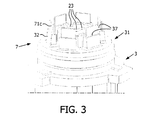
- Figures 3 depicts the case of inner bracing means.
- Figure 5 may also depict this case provided that it is taken due account of the fact that in that case, the reinforcement device is not visible because it is housed in the catch element 31 of the lamp socket 3.
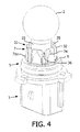
- Figure 4 depicts the case of outer bracing means.
- the heads of the catch flanges 32 have been cut out in order to show the structure of the catch element 31 equipped with an inner reinforcement device 5, such as the reinforcement device depicted on Figure 2 .
- the base of the catch flanges 32 is provided with a housing 37 adapted for receiving the leaf spring 71c.
- the housing 37 matches the shape of the leaf spring 71c so that the leaf spring 71 is not loose inside the housing 37. Moreover, this improves the bracing effect of the leaf spring 71 on the catch flanges 32.
- the lamp socket comprises housings 23 for receiving current conductive elements of a lamp 2. This is a conventional feature that does not necessitate further developments.
- Figure 4 illustrate another embodiment of the invention, wherein a catch element 31 is reinforced with an outer reinforcement device 5.
- the reinforcement device is similar to that of Figure 1 .
- a vehicle may be equipped with a lighting device assembly as disclosed herein.
- the processes for incorporating such lighting device assemblies are commonly known.
- Vehicles may be cars, motorcycles, trucks, boats...
Landscapes
- Engineering & Computer Science (AREA)
- General Engineering & Computer Science (AREA)
- Mechanical Engineering (AREA)
- Non-Portable Lighting Devices Or Systems Thereof (AREA)
- Fastening Of Light Sources Or Lamp Holders (AREA)
Description
- The invention relates to a reinforcement device for a lighting device socket and to a lighting device assembly which comprises such a reinforcement device.
- High performance lamps, such as HiPer Vision lamps by Philips, are interesting in the automotive industry for various reasons, among which because they have a useful life that is of the same order as that of a vehicle equipped with such lamps. In other words, it is seldom necessary to replace these lamps.
- To prevent deterioration of high performance lamps, they are usually assembled to the lamp socket through a clickable plastic element.
- A
lighting device assembly 1 of the prior art, as depicted onFigure 5 , comprises alamp 2 and alamp socket 3. The lamp socket contains the necessary electric connections in order to supply power to thelamp 2. Thelamp 2 has alamp bulb 21 and alamp base 22 which cooperates with thelamp socket 3 for power supply and positioning, for instance with current conducting elements (not shown) lodged in corresponding housings provided on thelamp socket 3. In order to prevent thelamp 2 from being dislodged from thelamp socket 3. thelamp socket 3 is equipped withcatch element 31, which comprises a plurality ofcatch flanges 32. Thecatch flanges 32 extend perpendicularly to the lamp socket plane. They may be regularly arranged along a circle. The catch flanges comprise aflange head 33 and aleg 34. Theflange head 33 has a bevelled guidingsurface 35 which ends at ashoulder 36. When alamp 2 is pushed in the lamp socket, thecatch flanges 32 are pushed ouwardly along their bevelled guidingsurface 33 until theshoulder 36 engages with thebase 22 of thelamp 2. Thus, thelamp 2 is assembled to thelamp socket 3 with aclickable catch element 31. The lamp socket may be made of a heat resistant plastic material, in order to prevent damage to thelamp 2. - However, in various appliances such as daytime running appliances where the
catch element 31, and more particularly thecatch flanges 32, undergoes prolonged mechanical stress under long term exposure to heat, thecatch element 31 may suffer permanent deformation. Such observations have been made after a long time span, for instance from a few weeks to a few months. This may result in thelamp 2 becoming loose in thelamp socket 3. which is undesirable for various reasons such as security or obligation to remove the lamp assembly and replace it although the lamp has not reached its useful life yet. - It is an object of embodiments of the invention to avoid the undesirable effects of permanent plastic deformation of a lighting device socket, so as, inter alia, to prevent loosening of a lighting device and to prolong the useful life of a lighting device assembly.
- To this end, an embodiment of the invention proposes a reinforcement device for a catch element of a lighting device socket, said catch element comprising a plurality of catch flanges for engaging with the base of a lighting device when a lighting device is pushed in said lighting device socket, said catch flanges extending perpendicularly to the lighting device socket plane, wherein said reinforcement device comprises a ring and bracing means integral with said ring and capable of bracing at least one catch flange of said catch element against the base of a lighting device when a lighting device is positioned in said lighting device socket.
- In the present application, the expression "lighting device" relates to any device capable of emitting light, such as a lamp, a LED, an OLED, and so on.
- In an embodiment of the invention, said ring comprises positioning means for positioning rotationally said reinforcement device with respect to said catch element of said lighting device socket. In another embodiment, said bracing means comprise at least one leaf spring extending from the ring. In yet another embodiment, at least one leaf spring comprises means for positioning axially said reinforcement device with respect to said catch element of said lighting device socket.
- Another embodiment of the invention proposes a lighting device socket comprising a housing for receiving current conductive elements of a lighting device, a catch element comprising a plurality of catch flanges for engaging with the base of a lighting device when said lighting device is pushed in said lighting device socket, said catch flanges extending perpendicularly to the lighting device socket plane, and further comprising a reinforcement device comprising a ring and bracing means integral with said ring and capable of bracing at least one catch flange of said catch element against the base of a lighting device when a lighting device is positioned in said lighting device socket.
- In an embodiment, said bracing means comprise at least one leaf spring extending from the ring. In another embodiment, the base of said catch flanges is provided with a housing adapted for receiving said leaf spring, such that said bracing means are inner bracing means. In a further embodiment, said leaf spring presses against said catch flange, such that said bracing means are outer bracing means.
- A further embodiment of the invention relates to a lighting device assembly comprising a lighting device socket as disclosed herein and a lighting device engaged in said lighting device socket.
- Embodiments of the invention also relate to a vehicle equipped with at least one lighting device socket or at least one lighting device assembly as disclosed herein.
- These and other aspects, features and advantages of the invention will become apparent to those skilled in the art upon reading the disclosure provided here in connection with the attached drawings. The detailed description, while indicating preferred embodiments of the invention, is only given by way of illustration.
- The invention will now be described in more details by way of example with reference to the accompanying drawings, in which:
-
Figures 1 and 2 show a perspective view of a reinforcement device according to first and second embodiments of the invention. -
Figure 3 shows a perspective partial view of a lamp socket comprising a reinforcement device as shown onFigure 2 . -
Figure 4 shows a perspective view of a lamp assembly comprising an outer reinforcement device such as the reinforcement device shown onFigure 1 . -
Figure 5 shows a perspective view of a prior art lamp assembly.Figure 5 may also be interpreted as showing a perspective view of a lamp assembly comprising an inner reinforcement device such as the reinforcement device shown onFigure 2 . - It must be noted that as used in this specification and the appended claims, the singular forms "a", "an"', and "the" include plural referents unless the context clearly dictates otherwise. Unless defined otherwise, all technical and scientific terms herein have the same meaning as commonly understood by one of ordinary skill in the art to which this invention belongs.
- Although the described examples relate to a lamp, such as an incandescent lamp or a discharge lamp, it may be applied to any kind of lighting device, such a LED or an OLED.
-
Figures 1 and 2 depict first and second embodiments of areinforcement device 5 useful for reinforcing a catch element of a lamp socket. For the purpose of description, reference is also made toFigure 5 . Thereinforcement devices 5 comprise aring 6 and bracing means 7 integral with thering 6. Preferably, the bracing means 7 comprise at least oneleaf spring ring 6. The leaf springs 71 have a proximal zone, close to thering 6 and adistal extremity 72a. 72b, 72c (collectively denoted 72). The leaf springs 71 are slightly inclined towards thecentre 62 of thering 6 so that the distal extremity 72 of the leaf springs 71 are arranged on a virtual ring which has smaller dimensions than thering 6. Thus, when thereinforcement device 5 is assembled to thelamp socket 3, theinner surface catch flanges 32 of thelamp socket 3 and braces said catchflanges 32 against thebase 22 oflamp 2 when a lamp is positioned in saidlamp socket 3. In the event that thecatch flanges 32 suffer from a mechanical deformation, the bracing means 7 prevent the mechanical deformation from appearing. - In a preferred embodiment, the bracing means 7 comprise as many leaf springs 71 as there are
catch flanges 32 on thecatch element 31 of thelamp socket 3. In such a configuration, one leaf spring 71 cooperates with onecatch flange 32. This is illustrated onFigures 1 to 4 , where the catch element comprises sixcatch flanges 32 and where the reinforcement device comprises six leaf springs 71. However, the number of six catch flanges and six leaf springs is not compulsory. Preferably, thecatch element 31 and the bracing means 7 comprise at least two diametricallyopposed catch flanges 32 and leaf springs 71. An advantageous feature is that thecatch flanges 32 and the leaf springs 71 be arranged equidistantly around thecatch element 31 and thering 6. In another embodiment, the bracing means comprise only two diametrically opposing leaf springs 71. - In an advantageous embodiment, the
ring 6 is a positioning ring. Thepositioning ring 6 comprises means for imparting a desired position to thereinforcement device 5 with respect of thecatch element 31 of alamp socket 3. For instance, theinner profile 61 of thepositioning ring 6 is provided so that it matches the outer profile of thecatch element 2. In the depicted embodiments, theinner profile 61 of thepositioning ring 6 is provided so that it matches the outer profile of thecatch element 32 are regular hexagon-shaped. Thus, thereinforcement device 5 can be easily fitted with respect to thecatch element 31. In another embodiment, thering 6 is provided with apositioning slot 63 which may cooperate with a positioning nib of thecatch element 31. Thus thereinforcement device 5 may be positioned rotationally with respect to thecatch element 31. - As shown on
Figure 1 , the bracing means 7 may comprisedifferent leaf springs distal extremity 72b of aleaf spring 71b may be provided with anotch 74 extending inwardly from theleaf spring 71b towards thecentre 62 of thering 6. When thereinforcement device 5 is assembled with thecatch element 31, thisnotch 74 may prevent thereinforcement device 5 from sliding axially along thecatch element 31. For instance, sliding may occur with time under the effect of vibrations from an automotive vehicle. Thus, thereinforcement device 5 is positioned axially with respect of thecatch element 31. - In a preferred embodiment, the
reinforcement device 5 is made of metal or of metal alloy. Various metal forming processes may be implemented for manufacturing thereinforcement device 5. For instance, metal stamping is a process employed in manufacturing metal parts with a specific design. A metal or metal alloy sheet is used as the stock. This stock is either stamped on a press using dies and punches or drawn into shapes on hydraulic deep drawing machines. Metal stamping processes use dies (female component of the stamp) and punches (male component of the stamp) to cut the metal into the required shape. Press machine tools are used in the stamping process. The die, made of hardened steel, has a contour that matches the shape of the finished part and is mounted on the table of the press. The punch, usually made of hardened tool steel or carbide, also matches the contour of the part but is slightly smaller to allow clearance between the die and the punch. It is mounted in the head or the turret, which moves down and punches the metal. The thickness of the sheet metal does not change during this process. Other techniques may be used such as fine blanking, deep drawing or progressive die stamping. - The
reinforcement device 5 may act as an inner bracing means or as an outer bracing means. They may be compared to an inner skeleton or an outer skeleton.Figures 3 depicts the case of inner bracing means.Figure 5 may also depict this case provided that it is taken due account of the fact that in that case, the reinforcement device is not visible because it is housed in thecatch element 31 of thelamp socket 3.Figure 4 depicts the case of outer bracing means. - On
Figure 3 , the heads of thecatch flanges 32 have been cut out in order to show the structure of thecatch element 31 equipped with aninner reinforcement device 5, such as the reinforcement device depicted onFigure 2 . In this embodiment, the base of the catch flanges 32 is provided with ahousing 37 adapted for receiving theleaf spring 71c. Advantageously, thehousing 37 matches the shape of theleaf spring 71c so that the leaf spring 71 is not loose inside thehousing 37. Moreover, this improves the bracing effect of the leaf spring 71 on thecatch flanges 32. - Moreover, the lamp socket comprises
housings 23 for receiving current conductive elements of alamp 2. This is a conventional feature that does not necessitate further developments. -
Figure 4 illustrate another embodiment of the invention, wherein acatch element 31 is reinforced with anouter reinforcement device 5. The reinforcement device is similar to that ofFigure 1 . - A vehicle may be equipped with a lighting device assembly as disclosed herein. The processes for incorporating such lighting device assemblies are commonly known. Vehicles may be cars, motorcycles, trucks, boats...
Claims (8)
- A lighting device socket (3) comprising a housing (23) for receiving current conductive elements of a lighting device (2), a catch element (31) comprising a plurality of catch flanges (32) for engaging with the base (22) of a lighting device (2) when a lighting device (2) is pushed in said lighting device socket (3), said catch flanges (32) extending perpendicularly to the lighting device socket plane, and further comprising a reinforcement device (5) comprising a ring (6) and bracing means (7) integral with said ring (6) and capable of bracing at least one catch flange (32) of said catch element (31) against the base (22) of a lighting device (2) when a lighting device (2) is positioned in said lighting device socket (3).
- The lighting device socket (3) of claim 1, wherein said bracing means (7) comprise at least one leaf spring (7 1 a, 71b, 71 c) extending from the ring (6).
- The lighting device socket (3) of claim 2, wherein the base of said catch flanges (32) is provided with a housing (37) adapted for receiving said leaf spring (71c), such that said bracing means (7) are inner bracing means.
- The lighting device socket (3) of claim 2, wherein said leaf spring (71a, 71b) presses against said catch flange (32), such that said bracing means are outer bracing means.
- The lighting device socket (3) as claimed in claim 1, wherein said ring (6) comprises positioning means (61, 63) for positioning rotationally said reinforcement device (5) with respect to said catch element (31) of said lighting device socket (3).
- The lighting device socket (3) as claimed in claim 2, wherein at least one leaf spring (71b) comprises means (74) for positioning axially said reinforcement device (5) with respect to said catch element (31) of said lighting device socket (3).
- A lighting device assembly comprising a lighting device socket (3) as claimed in claim 1 and a lighting device (2) engaged in said lighting device socket (3).
- A vehicle equipped with at least one lighting device socket (3) as claimed in claim 1.
Priority Applications (1)
| Application Number | Priority Date | Filing Date | Title |
|---|---|---|---|
| EP20080763157 EP2158431B1 (en) | 2007-06-01 | 2008-05-30 | Reinforcement device, lighting device socket, lighting device assembly and vehicle |
Applications Claiming Priority (3)
| Application Number | Priority Date | Filing Date | Title |
|---|---|---|---|
| EP07290686 | 2007-06-01 | ||
| PCT/IB2008/052121 WO2008146258A1 (en) | 2007-06-01 | 2008-05-30 | Reinforcement device, lighting device socket, lighting device assembly and vehicle |
| EP20080763157 EP2158431B1 (en) | 2007-06-01 | 2008-05-30 | Reinforcement device, lighting device socket, lighting device assembly and vehicle |
Publications (2)
| Publication Number | Publication Date |
|---|---|
| EP2158431A1 EP2158431A1 (en) | 2010-03-03 |
| EP2158431B1 true EP2158431B1 (en) | 2012-10-03 |
Family
ID=39811607
Family Applications (1)
| Application Number | Title | Priority Date | Filing Date |
|---|---|---|---|
| EP20080763157 Active EP2158431B1 (en) | 2007-06-01 | 2008-05-30 | Reinforcement device, lighting device socket, lighting device assembly and vehicle |
Country Status (6)
| Country | Link |
|---|---|
| US (1) | US9097404B2 (en) |
| EP (1) | EP2158431B1 (en) |
| JP (1) | JP5430558B2 (en) |
| KR (1) | KR101460006B1 (en) |
| CN (1) | CN101680641B (en) |
| WO (1) | WO2008146258A1 (en) |
Families Citing this family (4)
| Publication number | Priority date | Publication date | Assignee | Title |
|---|---|---|---|---|
| IT1403019B1 (en) * | 2010-11-18 | 2013-09-27 | Automotive Lighting Rear Lamps Italia S P A | LAMPHOLDER FOR INCANDESCENT LAMPS AND AUTOMOTIVE HEADLAMP PROVIDED WITH THIS LAMPHOLDER |
| KR101276535B1 (en) * | 2012-06-11 | 2013-06-24 | (주)씨티엘 | Led lamp module |
| USD856938S1 (en) * | 2016-06-29 | 2019-08-20 | R&S Shaeffer Properties LLC | Socket assembly |
| USD845246S1 (en) * | 2016-07-26 | 2019-04-09 | Eaton Intelligent Power Limited | Electrical connector housing with asymmetric rectangular hot terminal edge slots and terminals with a rectangular edge protrusion |
Family Cites Families (21)
| Publication number | Priority date | Publication date | Assignee | Title |
|---|---|---|---|---|
| JPS5836147Y2 (en) * | 1979-06-21 | 1983-08-15 | 市光工業株式会社 | Socket structure for vehicle lights |
| US4513356A (en) * | 1982-01-13 | 1985-04-23 | Ford Motor Company | Replaceable lamp assembly and locking mechanism for a sealable reflector housing |
| DE3602234A1 (en) * | 1986-01-25 | 1987-07-30 | Hella Kg Hueck & Co | VEHICLE HEADLIGHTS |
| FR2604132B1 (en) * | 1986-09-18 | 1990-04-20 | Cibie Projecteurs | FIXING DEVICE FOR A MOTOR VEHICLE LAMP |
| US4964852A (en) | 1988-10-11 | 1990-10-23 | Tambrands, Inc. | Douche container and nozzle with intermediate one-way valve |
| US4898291A (en) | 1989-03-29 | 1990-02-06 | Sailors John C | Nursing bottle with removable pacifier |
| US5238152A (en) | 1992-02-24 | 1993-08-24 | Afa Products Inc. | Quick-locking child resistant bottle cap assembly |
| US5400685A (en) | 1992-06-02 | 1995-03-28 | Cappella; Carmen J. | Drumstick having rigid ring around tip |
| US5800183A (en) * | 1996-02-22 | 1998-09-01 | Tricon Industries Incorporated | Sealed socket assembly for a plug-in lamp and a method for assembling same |
| KR20010034590A (en) | 1998-03-09 | 2001-04-25 | 칼 쳉 퉁 콩 | Drink dispenser for collapsible liquid containers |
| US6139334A (en) * | 1998-09-16 | 2000-10-31 | Cooper Automotive Products, Inc. | Integral socket backplate |
| EP1048442B1 (en) | 1999-03-31 | 2003-11-12 | Alcan Technology & Management AG | Plastic construction element with inserts |
| JP3907883B2 (en) * | 1999-10-12 | 2007-04-18 | 株式会社小糸製作所 | Vehicle lighting |
| JP2001143839A (en) * | 1999-11-17 | 2001-05-25 | Hirose Electric Co Ltd | Lamp socket |
| US6217340B1 (en) | 2000-02-24 | 2001-04-17 | Trw Inc. | Electrical connector assembly |
| US6260198B1 (en) | 2000-03-20 | 2001-07-17 | Pro-Hitter Corporation | Batting pad |
| JP3643758B2 (en) * | 2000-07-07 | 2005-04-27 | 株式会社小糸製作所 | Insulation plug for discharge lamp device and discharge lamp device |
| WO2004015331A1 (en) * | 2002-08-07 | 2004-02-19 | Koninklijke Philips Electronics N.V. | Device for placing a lamp in a reflector |
| US20050217155A1 (en) | 2004-03-30 | 2005-10-06 | Michael Santa Cruz | Hand gesture receiver |
| DE102004030109B4 (en) * | 2004-06-22 | 2006-06-14 | Yazaki Europe Ltd., Hemel Hempstead | Connecting device for releasably connecting a lamp to a reflector |
| EP1996859B1 (en) * | 2006-03-10 | 2010-10-27 | Koninklijke Philips Electronics N.V. | An automotive lamp provided with a bulb locked to the cap of the lamp |
-
2008
- 2008-05-30 KR KR1020097027572A patent/KR101460006B1/en active Active
- 2008-05-30 US US12/601,854 patent/US9097404B2/en active Active
- 2008-05-30 WO PCT/IB2008/052121 patent/WO2008146258A1/en not_active Ceased
- 2008-05-30 EP EP20080763157 patent/EP2158431B1/en active Active
- 2008-05-30 CN CN200880018460XA patent/CN101680641B/en active Active
- 2008-05-30 JP JP2010509939A patent/JP5430558B2/en active Active
Also Published As
| Publication number | Publication date |
|---|---|
| JP5430558B2 (en) | 2014-03-05 |
| CN101680641A (en) | 2010-03-24 |
| US20110228563A1 (en) | 2011-09-22 |
| JP2010529596A (en) | 2010-08-26 |
| WO2008146258A1 (en) | 2008-12-04 |
| EP2158431A1 (en) | 2010-03-03 |
| KR101460006B1 (en) | 2014-11-10 |
| KR20100029784A (en) | 2010-03-17 |
| US9097404B2 (en) | 2015-08-04 |
| CN101680641B (en) | 2012-01-11 |
Similar Documents
| Publication | Publication Date | Title |
|---|---|---|
| US9097404B2 (en) | Reinforcement device, lighting device socket, lighting device assembly and vehicle | |
| US8006592B2 (en) | Burr elimination device for camshaft | |
| CN108150508B (en) | High-strength light-structure bolt with double-profile action part | |
| DE102015201153A1 (en) | lighting device | |
| CN105909632A (en) | Fastening element for fixing two components to each other | |
| US20110252595A1 (en) | Fitting member | |
| KR102100451B1 (en) | The Manufacturing Method of Rivet Type Battery Terminal Plate | |
| WO2013111581A1 (en) | Bulb socket and lighting system | |
| CN204885483U (en) | Terminal type wiring terminal, compressor and upper cover assembly thereof | |
| KR101375130B1 (en) | Aiming bolt of head lamp for vehicle and manufacturing method thereof | |
| US4649620A (en) | Method of making a socket-type key for an a anti-theft lug nut having a surface key pattern | |
| CN109397171B (en) | Small-size combined sealing element assembling tool and assembling method | |
| KR100969375B1 (en) | Hall deburring device | |
| CN116787827A (en) | Tire mold with replaceable movable blocks | |
| CN216758474U (en) | Screw die structure for screw machining | |
| US8739750B2 (en) | Mechanical bucket tappet | |
| CN221271807U (en) | Pressing die structure for manufacturing car lamp | |
| CN224254128U (en) | A cold heading die for screws | |
| US7263774B2 (en) | Plain bearing shell and method for producing a holding projection on a plain bearing shell | |
| CN101305441A (en) | A lamp comprising a cap with a key function and a method for manufacturing such lamp | |
| CN202220632U (en) | Thrust structure of camshaft of engine | |
| CN104136144A (en) | Method used to form sprockets | |
| KR101438820B1 (en) | Vehicle punch retainer assembly | |
| CN213887897U (en) | Automobile parts punching press location structure | |
| KR200329160Y1 (en) | Die of bolt for looseness protect |
Legal Events
| Date | Code | Title | Description |
|---|---|---|---|
| PUAI | Public reference made under article 153(3) epc to a published international application that has entered the european phase |
Free format text: ORIGINAL CODE: 0009012 |
|
| 17P | Request for examination filed |
Effective date: 20100104 |
|
| AK | Designated contracting states |
Kind code of ref document: A1 Designated state(s): AT BE BG CH CY CZ DE DK EE ES FI FR GB GR HR HU IE IS IT LI LT LU LV MC MT NL NO PL PT RO SE SI SK TR |
|
| AX | Request for extension of the european patent |
Extension state: AL BA MK RS |
|
| DAX | Request for extension of the european patent (deleted) | ||
| 17Q | First examination report despatched |
Effective date: 20110429 |
|
| GRAP | Despatch of communication of intention to grant a patent |
Free format text: ORIGINAL CODE: EPIDOSNIGR1 |
|
| GRAS | Grant fee paid |
Free format text: ORIGINAL CODE: EPIDOSNIGR3 |
|
| GRAA | (expected) grant |
Free format text: ORIGINAL CODE: 0009210 |
|
| AK | Designated contracting states |
Kind code of ref document: B1 Designated state(s): AT BE BG CH CY CZ DE DK EE ES FI FR GB GR HR HU IE IS IT LI LT LU LV MC MT NL NO PL PT RO SE SI SK TR |
|
| REG | Reference to a national code |
Ref country code: GB Ref legal event code: FG4D |
|
| REG | Reference to a national code |
Ref country code: AT Ref legal event code: REF Ref document number: 578149 Country of ref document: AT Kind code of ref document: T Effective date: 20121015 Ref country code: CH Ref legal event code: EP |
|
| REG | Reference to a national code |
Ref country code: IE Ref legal event code: FG4D |
|
| REG | Reference to a national code |
Ref country code: DE Ref legal event code: R096 Ref document number: 602008019160 Country of ref document: DE Effective date: 20121206 |
|
| REG | Reference to a national code |
Ref country code: AT Ref legal event code: MK05 Ref document number: 578149 Country of ref document: AT Kind code of ref document: T Effective date: 20121003 |
|
| PG25 | Lapsed in a contracting state [announced via postgrant information from national office to epo] |
Ref country code: SI Free format text: LAPSE BECAUSE OF FAILURE TO SUBMIT A TRANSLATION OF THE DESCRIPTION OR TO PAY THE FEE WITHIN THE PRESCRIBED TIME-LIMIT Effective date: 20121003 |
|
| REG | Reference to a national code |
Ref country code: NL Ref legal event code: VDEP Effective date: 20121003 |
|
| REG | Reference to a national code |
Ref country code: DE Ref legal event code: R081 Ref document number: 602008019160 Country of ref document: DE Owner name: PHILIPS INTELLECTUAL PROPERTY & STANDARDS GMBH, DE Free format text: FORMER OWNER: PHILIPS INTELLECTUAL PROPERTY &, KONINKLIJKE PHILIPS ELECTRONICS, , NL Effective date: 20130123 Ref country code: DE Ref legal event code: R081 Ref document number: 602008019160 Country of ref document: DE Owner name: PHILIPS DEUTSCHLAND GMBH, DE Free format text: FORMER OWNER: PHILIPS INTELLECTUAL PROPERTY &, KONINKLIJKE PHILIPS ELECTRONICS, , NL Effective date: 20130123 Ref country code: DE Ref legal event code: R081 Ref document number: 602008019160 Country of ref document: DE Owner name: PHILIPS GMBH, DE Free format text: FORMER OWNER: PHILIPS INTELLECTUAL PROPERTY &, KONINKLIJKE PHILIPS ELECTRONICS, , NL Effective date: 20130123 Ref country code: DE Ref legal event code: R081 Ref document number: 602008019160 Country of ref document: DE Owner name: PHILIPS GMBH, DE Free format text: FORMER OWNERS: PHILIPS INTELLECTUAL PROPERTY & STANDARDS GMBH, 20099 HAMBURG, DE; KONINKLIJKE PHILIPS ELECTRONICS N.V., EINDHOVEN, NL Effective date: 20130123 |
|
| REG | Reference to a national code |
Ref country code: DE Ref legal event code: R084 Ref document number: 602008019160 Country of ref document: DE Effective date: 20130123 |
|
| REG | Reference to a national code |
Ref country code: LT Ref legal event code: MG4D |
|
| PG25 | Lapsed in a contracting state [announced via postgrant information from national office to epo] |
Ref country code: LT Free format text: LAPSE BECAUSE OF FAILURE TO SUBMIT A TRANSLATION OF THE DESCRIPTION OR TO PAY THE FEE WITHIN THE PRESCRIBED TIME-LIMIT Effective date: 20121003 Ref country code: SE Free format text: LAPSE BECAUSE OF FAILURE TO SUBMIT A TRANSLATION OF THE DESCRIPTION OR TO PAY THE FEE WITHIN THE PRESCRIBED TIME-LIMIT Effective date: 20121003 Ref country code: FI Free format text: LAPSE BECAUSE OF FAILURE TO SUBMIT A TRANSLATION OF THE DESCRIPTION OR TO PAY THE FEE WITHIN THE PRESCRIBED TIME-LIMIT Effective date: 20121003 Ref country code: NL Free format text: LAPSE BECAUSE OF FAILURE TO SUBMIT A TRANSLATION OF THE DESCRIPTION OR TO PAY THE FEE WITHIN THE PRESCRIBED TIME-LIMIT Effective date: 20121003 Ref country code: ES Free format text: LAPSE BECAUSE OF FAILURE TO SUBMIT A TRANSLATION OF THE DESCRIPTION OR TO PAY THE FEE WITHIN THE PRESCRIBED TIME-LIMIT Effective date: 20130114 Ref country code: IS Free format text: LAPSE BECAUSE OF FAILURE TO SUBMIT A TRANSLATION OF THE DESCRIPTION OR TO PAY THE FEE WITHIN THE PRESCRIBED TIME-LIMIT Effective date: 20130203 Ref country code: NO Free format text: LAPSE BECAUSE OF FAILURE TO SUBMIT A TRANSLATION OF THE DESCRIPTION OR TO PAY THE FEE WITHIN THE PRESCRIBED TIME-LIMIT Effective date: 20130103 Ref country code: HR Free format text: LAPSE BECAUSE OF FAILURE TO SUBMIT A TRANSLATION OF THE DESCRIPTION OR TO PAY THE FEE WITHIN THE PRESCRIBED TIME-LIMIT Effective date: 20121003 |
|
| PG25 | Lapsed in a contracting state [announced via postgrant information from national office to epo] |
Ref country code: LV Free format text: LAPSE BECAUSE OF FAILURE TO SUBMIT A TRANSLATION OF THE DESCRIPTION OR TO PAY THE FEE WITHIN THE PRESCRIBED TIME-LIMIT Effective date: 20121003 Ref country code: GR Free format text: LAPSE BECAUSE OF FAILURE TO SUBMIT A TRANSLATION OF THE DESCRIPTION OR TO PAY THE FEE WITHIN THE PRESCRIBED TIME-LIMIT Effective date: 20130104 Ref country code: PT Free format text: LAPSE BECAUSE OF FAILURE TO SUBMIT A TRANSLATION OF THE DESCRIPTION OR TO PAY THE FEE WITHIN THE PRESCRIBED TIME-LIMIT Effective date: 20130204 Ref country code: PL Free format text: LAPSE BECAUSE OF FAILURE TO SUBMIT A TRANSLATION OF THE DESCRIPTION OR TO PAY THE FEE WITHIN THE PRESCRIBED TIME-LIMIT Effective date: 20121003 Ref country code: BE Free format text: LAPSE BECAUSE OF FAILURE TO SUBMIT A TRANSLATION OF THE DESCRIPTION OR TO PAY THE FEE WITHIN THE PRESCRIBED TIME-LIMIT Effective date: 20121003 |
|
| PG25 | Lapsed in a contracting state [announced via postgrant information from national office to epo] |
Ref country code: AT Free format text: LAPSE BECAUSE OF FAILURE TO SUBMIT A TRANSLATION OF THE DESCRIPTION OR TO PAY THE FEE WITHIN THE PRESCRIBED TIME-LIMIT Effective date: 20121003 |
|
| PG25 | Lapsed in a contracting state [announced via postgrant information from national office to epo] |
Ref country code: DK Free format text: LAPSE BECAUSE OF FAILURE TO SUBMIT A TRANSLATION OF THE DESCRIPTION OR TO PAY THE FEE WITHIN THE PRESCRIBED TIME-LIMIT Effective date: 20121003 Ref country code: EE Free format text: LAPSE BECAUSE OF FAILURE TO SUBMIT A TRANSLATION OF THE DESCRIPTION OR TO PAY THE FEE WITHIN THE PRESCRIBED TIME-LIMIT Effective date: 20121003 Ref country code: CZ Free format text: LAPSE BECAUSE OF FAILURE TO SUBMIT A TRANSLATION OF THE DESCRIPTION OR TO PAY THE FEE WITHIN THE PRESCRIBED TIME-LIMIT Effective date: 20121003 Ref country code: SK Free format text: LAPSE BECAUSE OF FAILURE TO SUBMIT A TRANSLATION OF THE DESCRIPTION OR TO PAY THE FEE WITHIN THE PRESCRIBED TIME-LIMIT Effective date: 20121003 Ref country code: BG Free format text: LAPSE BECAUSE OF FAILURE TO SUBMIT A TRANSLATION OF THE DESCRIPTION OR TO PAY THE FEE WITHIN THE PRESCRIBED TIME-LIMIT Effective date: 20130103 |
|
| PLBE | No opposition filed within time limit |
Free format text: ORIGINAL CODE: 0009261 |
|
| STAA | Information on the status of an ep patent application or granted ep patent |
Free format text: STATUS: NO OPPOSITION FILED WITHIN TIME LIMIT |
|
| PG25 | Lapsed in a contracting state [announced via postgrant information from national office to epo] |
Ref country code: IT Free format text: LAPSE BECAUSE OF FAILURE TO SUBMIT A TRANSLATION OF THE DESCRIPTION OR TO PAY THE FEE WITHIN THE PRESCRIBED TIME-LIMIT Effective date: 20121003 Ref country code: RO Free format text: LAPSE BECAUSE OF FAILURE TO SUBMIT A TRANSLATION OF THE DESCRIPTION OR TO PAY THE FEE WITHIN THE PRESCRIBED TIME-LIMIT Effective date: 20121003 |
|
| 26N | No opposition filed |
Effective date: 20130704 |
|
| REG | Reference to a national code |
Ref country code: DE Ref legal event code: R097 Ref document number: 602008019160 Country of ref document: DE Effective date: 20130704 |
|
| PG25 | Lapsed in a contracting state [announced via postgrant information from national office to epo] |
Ref country code: CY Free format text: LAPSE BECAUSE OF FAILURE TO SUBMIT A TRANSLATION OF THE DESCRIPTION OR TO PAY THE FEE WITHIN THE PRESCRIBED TIME-LIMIT Effective date: 20121003 |
|
| PG25 | Lapsed in a contracting state [announced via postgrant information from national office to epo] |
Ref country code: MC Free format text: LAPSE BECAUSE OF FAILURE TO SUBMIT A TRANSLATION OF THE DESCRIPTION OR TO PAY THE FEE WITHIN THE PRESCRIBED TIME-LIMIT Effective date: 20121003 |
|
| REG | Reference to a national code |
Ref country code: CH Ref legal event code: PL |
|
| PG25 | Lapsed in a contracting state [announced via postgrant information from national office to epo] |
Ref country code: LI Free format text: LAPSE BECAUSE OF NON-PAYMENT OF DUE FEES Effective date: 20130531 Ref country code: CH Free format text: LAPSE BECAUSE OF NON-PAYMENT OF DUE FEES Effective date: 20130531 |
|
| REG | Reference to a national code |
Ref country code: IE Ref legal event code: MM4A |
|
| PG25 | Lapsed in a contracting state [announced via postgrant information from national office to epo] |
Ref country code: IE Free format text: LAPSE BECAUSE OF NON-PAYMENT OF DUE FEES Effective date: 20130530 |
|
| REG | Reference to a national code |
Ref country code: DE Ref legal event code: R081 Ref document number: 602008019160 Country of ref document: DE Owner name: PHILIPS GMBH, DE Free format text: FORMER OWNER: PHILIPS INTELLECTUAL PROPERTY & STANDARDS GMBH, 52066 AACHEN, DE Effective date: 20140331 Ref country code: DE Ref legal event code: R081 Ref document number: 602008019160 Country of ref document: DE Owner name: PHILIPS DEUTSCHLAND GMBH, DE Free format text: FORMER OWNER: PHILIPS INTELLECTUAL PROPERTY & STANDARDS GMBH, 52066 AACHEN, DE Effective date: 20140331 |
|
| REG | Reference to a national code |
Ref country code: FR Ref legal event code: CD Owner name: PHILIPS INTELLECTUAL PROPERTY & STANDARDS GMBH, DE Effective date: 20141126 Ref country code: FR Ref legal event code: CA Effective date: 20141126 Ref country code: FR Ref legal event code: CD Owner name: KONINKLIJKE PHILIPS ELECTRONICS N.V., NL Effective date: 20141126 |
|
| PG25 | Lapsed in a contracting state [announced via postgrant information from national office to epo] |
Ref country code: MT Free format text: LAPSE BECAUSE OF FAILURE TO SUBMIT A TRANSLATION OF THE DESCRIPTION OR TO PAY THE FEE WITHIN THE PRESCRIBED TIME-LIMIT Effective date: 20121003 |
|
| PG25 | Lapsed in a contracting state [announced via postgrant information from national office to epo] |
Ref country code: TR Free format text: LAPSE BECAUSE OF FAILURE TO SUBMIT A TRANSLATION OF THE DESCRIPTION OR TO PAY THE FEE WITHIN THE PRESCRIBED TIME-LIMIT Effective date: 20121003 |
|
| REG | Reference to a national code |
Ref country code: DE Ref legal event code: R081 Ref document number: 602008019160 Country of ref document: DE Owner name: PHILIPS GMBH, DE Free format text: FORMER OWNER: PHILIPS DEUTSCHLAND GMBH, 20099 HAMBURG, DE |
|
| PG25 | Lapsed in a contracting state [announced via postgrant information from national office to epo] |
Ref country code: LU Free format text: LAPSE BECAUSE OF NON-PAYMENT OF DUE FEES Effective date: 20130530 Ref country code: HU Free format text: LAPSE BECAUSE OF FAILURE TO SUBMIT A TRANSLATION OF THE DESCRIPTION OR TO PAY THE FEE WITHIN THE PRESCRIBED TIME-LIMIT; INVALID AB INITIO Effective date: 20080530 |
|
| REG | Reference to a national code |
Ref country code: FR Ref legal event code: PLFP Year of fee payment: 9 |
|
| REG | Reference to a national code |
Ref country code: FR Ref legal event code: PLFP Year of fee payment: 10 |
|
| REG | Reference to a national code |
Ref country code: FR Ref legal event code: PLFP Year of fee payment: 11 |
|
| REG | Reference to a national code |
Ref country code: GB Ref legal event code: 732E Free format text: REGISTERED BETWEEN 20180920 AND 20180926 |
|
| REG | Reference to a national code |
Ref country code: DE Ref legal event code: R081 Ref document number: 602008019160 Country of ref document: DE Owner name: LUMILEDS HOLDING B.V., NL Free format text: FORMER OWNER: PHILIPS GMBH, 20099 HAMBURG, DE |
|
| PGFP | Annual fee paid to national office [announced via postgrant information from national office to epo] |
Ref country code: GB Payment date: 20250529 Year of fee payment: 18 |
|
| PGFP | Annual fee paid to national office [announced via postgrant information from national office to epo] |
Ref country code: FR Payment date: 20250522 Year of fee payment: 18 |
|
| PGFP | Annual fee paid to national office [announced via postgrant information from national office to epo] |
Ref country code: DE Payment date: 20250730 Year of fee payment: 18 |