EP2157990B1 - Inhalator zur verabreichung eines pulverförmigen medikaments - Google Patents
Inhalator zur verabreichung eines pulverförmigen medikaments Download PDFInfo
- Publication number
- EP2157990B1 EP2157990B1 EP08766981.8A EP08766981A EP2157990B1 EP 2157990 B1 EP2157990 B1 EP 2157990B1 EP 08766981 A EP08766981 A EP 08766981A EP 2157990 B1 EP2157990 B1 EP 2157990B1
- Authority
- EP
- European Patent Office
- Prior art keywords
- chamber
- aerosolization
- capsule
- air
- inhaler according
- Prior art date
- Legal status (The legal status is an assumption and is not a legal conclusion. Google has not performed a legal analysis and makes no representation as to the accuracy of the status listed.)
- Not-in-force
Links
Images


Classifications
-
- A—HUMAN NECESSITIES
- A61—MEDICAL OR VETERINARY SCIENCE; HYGIENE
- A61M—DEVICES FOR INTRODUCING MEDIA INTO, OR ONTO, THE BODY; DEVICES FOR TRANSDUCING BODY MEDIA OR FOR TAKING MEDIA FROM THE BODY; DEVICES FOR PRODUCING OR ENDING SLEEP OR STUPOR
- A61M15/00—Inhalators
- A61M15/0028—Inhalators using prepacked dosages, one for each application, e.g. capsules to be perforated or broken-up
-
- A—HUMAN NECESSITIES
- A61—MEDICAL OR VETERINARY SCIENCE; HYGIENE
- A61M—DEVICES FOR INTRODUCING MEDIA INTO, OR ONTO, THE BODY; DEVICES FOR TRANSDUCING BODY MEDIA OR FOR TAKING MEDIA FROM THE BODY; DEVICES FOR PRODUCING OR ENDING SLEEP OR STUPOR
- A61M15/00—Inhalators
- A61M15/009—Inhalators using medicine packages with incorporated spraying means, e.g. aerosol cans
-
- A—HUMAN NECESSITIES
- A61—MEDICAL OR VETERINARY SCIENCE; HYGIENE
- A61M—DEVICES FOR INTRODUCING MEDIA INTO, OR ONTO, THE BODY; DEVICES FOR TRANSDUCING BODY MEDIA OR FOR TAKING MEDIA FROM THE BODY; DEVICES FOR PRODUCING OR ENDING SLEEP OR STUPOR
- A61M2202/00—Special media to be introduced, removed or treated
- A61M2202/06—Solids
- A61M2202/064—Powder
Definitions
- the present invention relates to an inhaler for powder drug administration, applicable both for administration of drugs in the respiratory system therapy and for systemic administration of drugs.
- a drug finding its way to a respiratory system is in aerosol form, i.e. in form of a lasting dispersion of liquid drops or solids in the inhaled air.
- a liquid drug is transformed into an aerosol by atomizing the liquid using ultrasounds or by dispersing it by compressed air while passing through a nozzle.
- the therapeutic effect of inhalation depends on size of aerosol particles, and thus on the original size of powder particles. Proper effects are obtained for the aerosol particle diameters under 5 ⁇ m.
- Present trends and engineering opportunities indicate improved effectiveness of the aerosol therapy when the particle diameters in the powder of which the aerosol is formed are on the order of hundreds of nanometers.
- active substance For fine break-up of active substance, its particles are deposited over a surface of larger particles of pharmacologically neutral substance.
- particles of active substance become separated from carrier. Large diameter carrier particles a will be captured in head airways, while the smaller drug particles penetrate to further parts of the respiratory system.
- the powder is formed of drug substance particles, they hold together in the powder structure by cohesion forces, which strongly unite molecules together. To carry away particles of such structure, quite a high energy of the flowing-through air is needed. This can be achieved by special design of an applicator for powder transformation into the aerosol form.
- the powder either as pure active substance or in form of carrier-bonded particles of the same substance is fed to a powder inhaler from a container in form of a capsule or blister.
- a portion of drug contained in the container is determined by size of applied dose. Effectiveness of emptying the container of the portion of powder contained therein is an important feature in the powder inhaler design. Effectiveness of emptying the container and transforming the powder into aerosol form certifies of the inhaler quality.
- a powder inhaler as known from Polish patent application No. 370285 is intended for administration of drugs in patients with substantially impaired respiratory system.
- the inhaller has an aerodynamic chamber and air inlet passages shaped in such a way that the air flowing therethrough forms at least three groups of streams, where at least one of them flows into the chamber from the opposite end to the outlet of the chamber, and at least two of them flow in symmetrically from both sides, at acute angle to the axial centre line of the aerodynamic chamber. Centre lines of air streams flowing into the aerodynamic chamber intersect before reaching the place where the drug powder is carried away, producing thereby strongly turbulent flow even at low rates, owing to which the inhalation proceeds correctly.
- the inhaler for inhalation of powdered drugs provided with a system for emtying drug capsules has an aerodynamic chamber wherein the powder for inhalation is placed.
- the system for emtying drug capsules is composed of a motionless part - containing a tool for emptying the capsules and, possibly, a safety partition; and of a moving part - consisting of a capsule receptacle and a driving mechanism.
- a powder inhaller according to the patent specification PCT WO03/103563 is designed with a passage, and the air enters the passage through many openings spaced along the passage.
- the air flow rate through the passage can be adjusted by covering respective openings with fingers while taking a breath. This way however the uncertainty of the air flow is high, which results in lack of reproducibility of the medication doses inspired during consecutive inhalations.
- a powder inhaler wherein powder aerolization takes place as the compressed air stream, inflowing from an attached tank, flows through a drug-containing capsule, was disclosed in the WO2005/084735 patent specification.
- this solution as well as in case of pressure inhalers that dose suspended drugs, it is necessary to synchronize the moments of taking a breath and actuating the inhaler.
- the latter inhaler In order to improve breaking of the powder agglomerates, the latter inhaler has been provided with a narrow-passage nozzle.
- such solution requires that the air delivered from an attached air tank to be under much higher positive gauge pressure, which brings about additional constructional problems.
- the essence of the inhaler according to the invention is specified in claim 1.
- the aerosolization chamber at the top is joined to a capsule emptying chamber, and this chamber in turn is closed from the top with a lid serving also as a capsule holder, whereas the air inlet, through which the compressed air stream enters the aerosolization chamber tangently to its preferably concave bottom, is attached to a source of air for aerosolization, and a partition is provided in the aerosol outlet.
- the air inlet consists preferably of at least one slot, located at the bottom of the cylindrical aerosolization chamber and along a part of its circumference formed by opening angle not exceeding 120°.
- the air inlet consists of a set of openings located at the bottom of the cylindrical aerosolization chamber, within a sector corresponding to an opening angle not less than 30° and not exceeding 120°.
- the compressed air enters the aerosolization chamber in pulses from the source of air for aerosolization, through a shut-off valve mounted between the air inlet and the source of air for aerosolization.
- Volume of the air delivered into the aerosolization chamber, after expansion to standard conditions will exceed the volume of the aerosolization chamber.
- a guide provided with a return spring is seated preferably in a side wall of the body, and the shearing tool is mounted in the said guide and connected to a button located outside the inhaler. Further, a stabilizer of the capsule position is mounted in the capsule emptying chamber, where the said stabilizer locks the capsule in place when the capsule is pressed with the a shearing tool.
- the said guide provided with a return spring is seated in a side wall of the body, and the shearing tool is mounted inside the said guide and connected to the outside button, whereas a container releasing a strip of blisters, where each blister contains a dose of the administered medication, is located above the capsule emptying chamber.
- the source of air for aerosolization consists of a container, with a piston placed therein, and the said piston is connected to a power spring and a system of tension and release of the said spring, and the said container is attached to the aerosolization chamber through a joining passage.
- the source of air for aerosolization consists of a container with a piston placed therein, where the said piston is driven by a power spring and actuated by a spring tension and release system, and the said piston is set on a shaft aligned axially in the said cylindrical container.
- the said container is attached to the aerosolization chamber through a joining passage.
- the aerosolization chamber, the capsule emptying chamber and the capsule holder are joined to each other tight.
- a cross-section of the aerosolization chamber at a level of the aerosol outlet is larger than the aerosolization chamber cross-section at the air inlet level.
- the advantage of the powder drug inhaler according to the invention is its simple design, facilitating a correct course of inhalation and a good deposition of medication in the bronchial tree and pulmonary alveoli, particularly in patients with damaged respiratory function.
- the novel inhaler provides for an effective and reproducible emptying of a powder medication container, and for powder transformation into an aerosol form through delivery of additional air stream from the source of air for use in the aerosolization process, where the said air source is attached to this inhaler, and further this novel inhaler provides for inspiration of such formed aerosol into patient's lungs.
- Fig.1 axial sectional view of the inhaler provided with a cylindrical aerosolization chamber
- Fig.2 inhaler cross-section in the A-A plane of the air inlet
- Fig.3 capsule holder with a centrally located cavity
- Fig.4 capsule holder with an asymmetrically located cavity
- Fig.5 capsule emptying chamber, shearing tool seated in a side wall of the chamber
- Fig.6 capsule emptying chamber, shearing tool mounted into a guide
- Fig.7 capsule emptying chamber, shearing tool mounted into a guide, the chamber provided with a container to release a blister strip
- Fig.8 source of air for aerosolization, provided with a piston connected to a power spring and to a spring tension and release system
- Fig. 9 source of air for aerosolization, provided with a piston driven by a power spring and actuated by a spring tension and release
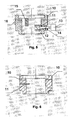
- the inhaler for administration of powder drugs has an aerosolization chamber 1 which is closed from the top with a lid, serving as a capsule holder 3.
- Compressed air from the source of air for aerosolization 4 is delivered to the aerosolization chamber 1 through a shut-off valve 5 mounted between the air inlet 6 and the source of air for aerosolization 4.
- a shut-off valve 5 mounted between the air inlet 6 and the source of air for aerosolization 4.
- the compressed air stream is delivered tangently to the bottom of the aerosolization chamber 1. Volume of air delivered into the aerosolization chamber 1, after expansion to standard conditions will exceed the volume of the aerosolization chamber 1.
- the air is taken off the aerosolization chamber 1 through the aerosol outlet 7, which is made in a side wall of the aerosolization chamber 1 on the opposite side to the air inlet 6, and the said aerosol outlet 7 is provided with a partition 8.
- the air inlet 6 constitutes a slot located at the bottom of the cylindrical aerosolization chamber 1 and along a part of its circumference formed by an opening angle ⁇ which is equal to 120°.
- the aerosolization chamber 1 is attached tight at the top to a capsule emptying chamber 2, and the said capsule emptying chamber 2 has a body 10, in the side wall whereof mounted is a shearing tool 11.
- Outside air inlet openings 16 are made in side walls of the body 10 in order to ensure the outside air flow into the inhaler at the time when the aerosol formed in the aerosolization chamber 1 is being inspired.
- the capsule emptying chamber 2 is closed tight by the capsule holder 3, having on its bottom side a cavity 9, in shape of a capsule with the administered medication.
- the cavity 9 is situated asymmetrically, and a larger part of the capsule placed therein protrudes outwards the cavity 9; at the moment when the capsule holder 3 is rotated, the protruding part of the capsule is shorn off by a fixed shearing tool 11, that serves to empty the capsules.
- the bottom part of the capsule, together with contained medication, falls down into the aerosolization chamber 1, wherefrom the drug powder is aerolized.
- the inhaler for administration of powder drugs made as in the first example, except that a guide 12 provided with a return spring 14 is seated in a side wall of a body 10 of the capsule emptying chamber 2, whereas the shearing tool 11 is connected to a button 13 located on the outside, and is mounted in the said guide 12. Further a capsule position stabilizer 15 is mounted in the capsule emptying chamber 2, and it locks the capsule in place when the capsule is pressed by the said shearing tool 11. Further a container 19 attached to the aerosolization chamber 1 through a joining passage 23, serves as a source of air for aerosolization 4. There is a piston 20 in the container 19, and the said piston 20 is connected to a power spring 21 and to a spring tension and release system 22.
- the compressed air is let into the aerosolization chamber 1 in pulses from the source of air for aerosolization 4, through a shut-off valve 5 mounted between the air inlet 6 and the source of air for aerosolization 4, where the air inlet 6 consists of a set of openings located at the bottom of the cylindrical aerosolization chamber 1, within a sector corresponding to an opening angle ⁇ equal to 30°.
- the aerosolization chamber 1 joins through the aerosol outlet 7 to a mouthpiece or a tip delivering the aerosol into a nasal passage.
- the inhaler for administration of powder drugs made as in the first or second example, except that the cavity 9 is located centrally in the capsule holder 3, and that the guide 12 provided with a return spring 14 is seated in a side wall of a body 10 of the capsule emptying chamber 2, whereas the shearing tool 11 connected to a button 13 located on the outside, is mounted in the said guide 12.
- the source of air for aerosolization 4 constitutes a container 19 with a piston 20 inside, where the said piston 20 is driven by a power spring 21 and actuated by a spring tension and release system 22.
- the piston 20 is set on a shaft aligned axially in a cylindrical container 19 and moves angularly round this axis, while the container 19 is attached to the aerosolization chamber 1 through a joining passage 23. Further a bottom of the aerosolization chamber 1 is concave in shape, therefore a dose of medication powder, when poured out of a capsule, or in case of incidental change of the inhaler position during preparation for inhalation, will not shift freely over the bottom of the aerosolization chamber 1.
- This inhaler model is fit for dosing medication packed in blisters.
- a dose of medication in a blister 17 placed on a strip 2 enters an area of the body 10 above the aerosolization chamber 1.
- a shearing tool 11 which is moving in a guide 12
- the powder pours out.
- the strip 18 is rigid, the blister 17 holds in position while being cut down with a shearing tool 11.
- the aerosolization chamber 1 is attached to a capsule emptying chamber 2 provided with a capsule opening device comprising a shearing tool 11, where the said shearing tool 11 opens a capsule by cutting down its bottom part. Once that part of the capsule has been cut down, the powder medication pours out over a concave surface of the bottom of the aerosolization chamber 1.
- Air from the attached source of air for aerosolization 4 passes through a shut-off valve 5 and enters the aerosolization chamber 1 through a slotted air inlet 6 located at the bottom of the aerosolization chamber 1 tangently to its bottom. The flowing air, owing to its kinetic energy, carries away the powder particles.
- the aerosol produced in the aerosolization chamber 1 is inhaled into the system through a mouthpiece or a nasal tip. Energy of inspiration is necessary only to introduce the aerosol into the respiratory system.
- the air for aerosolization can be taken also from a compressed air container attached to the aerosolization chamber 1, through a shut-off valve 5, or can be introduced into the chamber by a dynamic method through a mechanical air injection into the aerosolization chamber 1.
- the inhaler for administration of powder drugs made as in the first or second or third example, except that the cross-section of the aerosolization chamber 1 at the level of the aerosol outlet 7 is larger than the cross-section of the aerosolization chamber 1 at the air inlet 6 level, and that the air inlet 6 consists of thirty slots located at the bottom of the cylindrical aerosolization chamber 1 and along a part of its circumference formed by opening angle ⁇ equal to 120°, whereas the breadth of each slot corresponds to the length of a part of the circumference of the aerosolization chamber 1, formed by opening angle ⁇ equal to 2°.
Landscapes
- Health & Medical Sciences (AREA)
- Engineering & Computer Science (AREA)
- Bioinformatics & Cheminformatics (AREA)
- Pulmonology (AREA)
- Anesthesiology (AREA)
- Biomedical Technology (AREA)
- Heart & Thoracic Surgery (AREA)
- Hematology (AREA)
- Life Sciences & Earth Sciences (AREA)
- Animal Behavior & Ethology (AREA)
- General Health & Medical Sciences (AREA)
- Public Health (AREA)
- Veterinary Medicine (AREA)
- Medicinal Preparation (AREA)
Claims (15)
- Inhalator zur Verabreichung von pulverförmigen Medikamenten, der mit einer Feinzerstäubungskammer versehen ist, in der das Pulver zur Inhalation platziert ist, wobei der Lufteinlass zur Kammer und der Luftauslass aus der Kammer an den gegenüberliegenden Seitenwänden der Feinzerstäubungskammer angeordnet sind, dadurch gekennzeichnet, dass die Feinzerstäubungskammer (1) an seiner Oberseite an einer Kapselleerungskammer (2) angebracht ist, die von oben mit einem Deckel abgedeckt ist, der als ein Kapselhalter (3) dient, wobei der Lufteinlass (6), der dazu konfiguriert ist, das Eintreten eines Druckluftstroms in die Feinzerstäubungskammer (1) tangential zu ihrem Boden zu gestatten, einen Verbindungsdurchgang zu der Luftquelle (4) für die Feinzerstäubung herstellt, während im Aerosolauslass (7) eine Trennwand (8) vorgesehen ist.
- Inhalator nach Anspruch 1, dadurch gekennzeichnet, dass der Lufteinlass (6) aus mindestens einem Schlitz besteht, der am Boden der zylindrischen Feinzerstäubungskammer (1) angeordnet und entlang einem Teil seines Umfangs in einem Öffnungswinkel (α) von höchstens 120° gebildet ist.
- Inhalator nach Anspruch 1, dadurch gekennzeichnet, dass der Lufteinlass (6) aus einem Satz Öffnungen besteht, die am Boden der zylindrischen Feinzerstäubungskammer (1) innerhalb eines Sektors angeordnet sind, der einem Öffnungswinkel (α) von mindestens 30° und höchstens 120° entspricht.
- Inhalator nach Anspruch 1, dadurch gekennzeichnet, dass der Boden der Feinzerstäubungskammer (1) eine konkave Gestalt hat.
- Inhalator nach Anspruch 1, dadurch gekennzeichnet, dass die Druckluft im Pulsbetrieb von der Luftquelle (4) für die Feinzerstäubung, durch ein zwischen dem Lufteinlass (6) und der Luftquelle für die Feinzerstäubung montiertes Absperrventil, (5) in die Feinzerstäubungskammer (1) eintritt.
- Inhalator nach Anspruch 1, dadurch gekennzeichnet, dass das Volumen der in die Feinzerstäubungskammer (1) gelieferten Luft nach Expandierung auf Standardbedingungen das Volumen der Feinzerstäubungskammer (1) übersteigt.
- Inhalator nach Anspruch 1, dadurch gekennzeichnet, dass in der Bodenfläche des Kapselhalters (3) ein Hohlraum (9) ist, dessen Gestalt der der Kapsel entspricht, die das verabreichte Medikament enthält.
- Inhalator nach Anspruch 7, dadurch gekennzeichnet, dass der Hohlraum (9) mittig im Kapselhalter (3) angeordnet ist.
- Inhalator nach Anspruch 1, dadurch gekennzeichnet, dass die Kapselleerungskammer (2) mit einem Körper (10) versehen ist und ein Abscherwerkzeug (11) in einer Seitenwand davon montiert ist, während Außenlufteinlassöffnungen (16) in Seitenwänden des Körpers (10) ausgeführt sind, um die Außenluftströmung in den Inhalator hinein zu gewährleisten.
- Inhalator nach Anspruch 9, dadurch gekennzeichnet, dass eine mit einer Rückstellfeder (14) vorgesehene Führung (12) in einer Seitenwand des Körpers (10) sitzt und das Abscherwerkzeug (11), das mit einer außer dem Körper platzierten Taste (13) verbunden ist, mindestens teilweise in der Führung (12) montiert ist, und dass ausserdem ein Stabilisator der Kapselposition (15) in der Kapselleerungskammer (2) montiert ist und die Kapsel an Ort und Stelle verriegelt, wenn mit dem Abscherwerkzeug (11) auf die Kapsel gedrückt wird.
- Inhalator nach Anspruch 9, dadurch gekennzeichnet, dass eine mit einer Rückstellfeder (14) vorgesehene Führung (12) in einer Seitenwand des Körpers (10) sitzt und das Abscherwerkzeug (11), das mit einer außer dem Körper platzierten Taste (13) verbunden ist, mindestens teilweise in der Führung (12) montiert ist, während über der Kapselleerungskammer (2) ein Behälter (19) angeordnet ist, der Schritt für Schritt einen Streifen (18) von Blistern (17) freigibt, wobei jeder Blister (17) eine Dosis des verabreichten Medikaments enthält.
- Inhalator nach Anspruch 1, dadurch gekennzeichnet, dass die Luftquelle (4) für die Feinzerstäubung einen Behälter (19) darstellt, in dem ein Kolben (20) platziert ist, der mit einer Triebfeder (21) und mit einem Federspann-und-lösesystem (22) verbunden ist, während der Behälter (19) durch einen Verbindungsdurchgang (23) an der Feinzerstäubungskammer (1) angebracht ist.
- Inhalator nach Anspruch 1, dadurch gekennzeichnet, dass die Luftquelle (4) für die Feinzerstäubung einen Behälter (19) darstellt, in dem ein Kolben (20) platziert ist, wobei der Kolben (20) von einer Triebfeder (21) angetrieben und durch ein Federspann-und-lösesystem (22) betätigt wird und wobei der Kolben (20) an einem Schaft montiert ist, der axial im zylindrischen Behälter (19) ausgerichtet ist, während der Behälter (19) durch einen Verbindungsdurchgang (23) an der Feinzerstäubungskammer (1) angebracht ist.
- Inhalator nach Anspruch 1, dadurch gekennzeichnet, dass die Feinzerstäubungskammer (1), die Kapselleerungskammer (2) und der Kapselhalter (3) eng aneinander angebracht sind.
- Inhalator nach Anspruch 1, dadurch gekennzeichnet, dass der Querschnitt der Feinzerstäubungskammer (1) auf der Höhe des Aerosolauslasses (7) größer als der Querschnitt der Feinzerstäubungskammer (1) auf der Höhe des Lufteinlasses (6) ist.
Applications Claiming Priority (2)
| Application Number | Priority Date | Filing Date | Title |
|---|---|---|---|
| PL382684A PL211358B1 (pl) | 2007-06-18 | 2007-06-18 | Inhalator do podawania leków proszkowych |
| PCT/PL2008/000039 WO2008156381A1 (en) | 2007-06-18 | 2008-05-29 | Inhaler for powder drug administration |
Publications (2)
| Publication Number | Publication Date |
|---|---|
| EP2157990A1 EP2157990A1 (de) | 2010-03-03 |
| EP2157990B1 true EP2157990B1 (de) | 2014-07-30 |
Family
ID=39811663
Family Applications (1)
| Application Number | Title | Priority Date | Filing Date |
|---|---|---|---|
| EP08766981.8A Not-in-force EP2157990B1 (de) | 2007-06-18 | 2008-05-29 | Inhalator zur verabreichung eines pulverförmigen medikaments |
Country Status (3)
| Country | Link |
|---|---|
| EP (1) | EP2157990B1 (de) |
| PL (1) | PL211358B1 (de) |
| WO (1) | WO2008156381A1 (de) |
Cited By (1)
| Publication number | Priority date | Publication date | Assignee | Title |
|---|---|---|---|---|
| DE102016120413B3 (de) * | 2016-10-26 | 2018-02-01 | Meister Eber GmbH | Inhalationsvorrichtung mit einer Kapsel und Verfahren zur Inhalation |
Family Cites Families (7)
| Publication number | Priority date | Publication date | Assignee | Title |
|---|---|---|---|---|
| US4069819A (en) * | 1973-04-13 | 1978-01-24 | Societa Farmaceutici S.P.A. | Inhalation device |
| GB1479283A (en) * | 1973-07-23 | 1977-07-13 | Bespak Industries Ltd | Inhaler for powdered medicament |
| JPS63143081A (ja) * | 1986-12-05 | 1988-06-15 | メクト株式会社 | 吸入器 |
| GB2353222B (en) * | 1999-06-23 | 2001-09-19 | Cambridge Consultants | Inhalers |
| GB2367756B (en) * | 2000-10-12 | 2003-01-08 | Bespak Plc | Dispensing apparatus |
| GB0205572D0 (en) * | 2002-03-09 | 2002-04-24 | Chawla Brinda P S | Medicament delivery and packaging |
| GB0217198D0 (en) * | 2002-07-25 | 2002-09-04 | Glaxo Group Ltd | Medicament dispenser |
-
2007
- 2007-06-18 PL PL382684A patent/PL211358B1/pl unknown
-
2008
- 2008-05-29 WO PCT/PL2008/000039 patent/WO2008156381A1/en active Application Filing
- 2008-05-29 EP EP08766981.8A patent/EP2157990B1/de not_active Not-in-force
Cited By (1)
| Publication number | Priority date | Publication date | Assignee | Title |
|---|---|---|---|---|
| DE102016120413B3 (de) * | 2016-10-26 | 2018-02-01 | Meister Eber GmbH | Inhalationsvorrichtung mit einer Kapsel und Verfahren zur Inhalation |
Also Published As
| Publication number | Publication date |
|---|---|
| PL382684A1 (pl) | 2008-12-22 |
| WO2008156381A1 (en) | 2008-12-24 |
| PL211358B1 (pl) | 2012-05-31 |
| EP2157990A1 (de) | 2010-03-03 |
Similar Documents
| Publication | Publication Date | Title |
|---|---|---|
| RU2150298C1 (ru) | Способ ожижения порошкообразного лекарственного препарата для ингаляции, ингалятор | |
| US5458135A (en) | Method and device for delivering aerosolized medicaments | |
| US6116239A (en) | Inhalation device | |
| JP6199375B2 (ja) | ネブライザ | |
| US6766799B2 (en) | Inhalation device | |
| US6983748B2 (en) | Dry powder inhaler | |
| TWI517868B (zh) | 吸入器(二) | |
| US20040211419A1 (en) | Inhalers | |
| JP2007526055A (ja) | 多チャネル型ノズルを有する粉末吸入器 | |
| CA2500262A1 (en) | Powder inhaler | |
| HU216405B (hu) | Hordozóelem por alakú gyógyszerek adagolására szolgáló inhalálókészülékhez | |
| GB2375310A (en) | Inhalers | |
| EP2157990B1 (de) | Inhalator zur verabreichung eines pulverförmigen medikaments | |
| NZ721338A (en) | Inhalable medicaments | |
| AU2002341219A1 (en) | Inhalers |
Legal Events
| Date | Code | Title | Description |
|---|---|---|---|
| PUAI | Public reference made under article 153(3) epc to a published international application that has entered the european phase |
Free format text: ORIGINAL CODE: 0009012 |
|
| 17P | Request for examination filed |
Effective date: 20091116 |
|
| AK | Designated contracting states |
Kind code of ref document: A1 Designated state(s): AT BE BG CH CY CZ DE DK EE ES FI FR GB GR HR HU IE IS IT LI LT LU LV MC MT NL NO PL PT RO SE SI SK TR |
|
| AX | Request for extension of the european patent |
Extension state: AL BA MK RS |
|
| DAX | Request for extension of the european patent (deleted) | ||
| GRAP | Despatch of communication of intention to grant a patent |
Free format text: ORIGINAL CODE: EPIDOSNIGR1 |
|
| INTG | Intention to grant announced |
Effective date: 20140224 |
|
| GRAS | Grant fee paid |
Free format text: ORIGINAL CODE: EPIDOSNIGR3 |
|
| GRAA | (expected) grant |
Free format text: ORIGINAL CODE: 0009210 |
|
| AK | Designated contracting states |
Kind code of ref document: B1 Designated state(s): AT BE BG CH CY CZ DE DK EE ES FI FR GB GR HR HU IE IS IT LI LT LU LV MC MT NL NO PL PT RO SE SI SK TR |
|
| REG | Reference to a national code |
Ref country code: GB Ref legal event code: FG4D |
|
| REG | Reference to a national code |
Ref country code: CH Ref legal event code: EP |
|
| REG | Reference to a national code |
Ref country code: AT Ref legal event code: REF Ref document number: 679654 Country of ref document: AT Kind code of ref document: T Effective date: 20140815 |
|
| REG | Reference to a national code |
Ref country code: IE Ref legal event code: FG4D |
|
| REG | Reference to a national code |
Ref country code: DE Ref legal event code: R096 Ref document number: 602008033597 Country of ref document: DE Effective date: 20140904 |
|
| REG | Reference to a national code |
Ref country code: AT Ref legal event code: MK05 Ref document number: 679654 Country of ref document: AT Kind code of ref document: T Effective date: 20140730 |
|
| REG | Reference to a national code |
Ref country code: NL Ref legal event code: VDEP Effective date: 20140730 |
|
| REG | Reference to a national code |
Ref country code: LT Ref legal event code: MG4D |
|
| PG25 | Lapsed in a contracting state [announced via postgrant information from national office to epo] |
Ref country code: LT Free format text: LAPSE BECAUSE OF FAILURE TO SUBMIT A TRANSLATION OF THE DESCRIPTION OR TO PAY THE FEE WITHIN THE PRESCRIBED TIME-LIMIT Effective date: 20140730 Ref country code: GR Free format text: LAPSE BECAUSE OF FAILURE TO SUBMIT A TRANSLATION OF THE DESCRIPTION OR TO PAY THE FEE WITHIN THE PRESCRIBED TIME-LIMIT Effective date: 20141031 Ref country code: PT Free format text: LAPSE BECAUSE OF FAILURE TO SUBMIT A TRANSLATION OF THE DESCRIPTION OR TO PAY THE FEE WITHIN THE PRESCRIBED TIME-LIMIT Effective date: 20141202 Ref country code: BG Free format text: LAPSE BECAUSE OF FAILURE TO SUBMIT A TRANSLATION OF THE DESCRIPTION OR TO PAY THE FEE WITHIN THE PRESCRIBED TIME-LIMIT Effective date: 20141030 Ref country code: ES Free format text: LAPSE BECAUSE OF FAILURE TO SUBMIT A TRANSLATION OF THE DESCRIPTION OR TO PAY THE FEE WITHIN THE PRESCRIBED TIME-LIMIT Effective date: 20140730 Ref country code: NO Free format text: LAPSE BECAUSE OF FAILURE TO SUBMIT A TRANSLATION OF THE DESCRIPTION OR TO PAY THE FEE WITHIN THE PRESCRIBED TIME-LIMIT Effective date: 20141030 Ref country code: SE Free format text: LAPSE BECAUSE OF FAILURE TO SUBMIT A TRANSLATION OF THE DESCRIPTION OR TO PAY THE FEE WITHIN THE PRESCRIBED TIME-LIMIT Effective date: 20140730 Ref country code: FI Free format text: LAPSE BECAUSE OF FAILURE TO SUBMIT A TRANSLATION OF THE DESCRIPTION OR TO PAY THE FEE WITHIN THE PRESCRIBED TIME-LIMIT Effective date: 20140730 |
|
| PG25 | Lapsed in a contracting state [announced via postgrant information from national office to epo] |
Ref country code: NL Free format text: LAPSE BECAUSE OF FAILURE TO SUBMIT A TRANSLATION OF THE DESCRIPTION OR TO PAY THE FEE WITHIN THE PRESCRIBED TIME-LIMIT Effective date: 20140730 Ref country code: AT Free format text: LAPSE BECAUSE OF FAILURE TO SUBMIT A TRANSLATION OF THE DESCRIPTION OR TO PAY THE FEE WITHIN THE PRESCRIBED TIME-LIMIT Effective date: 20140730 Ref country code: LV Free format text: LAPSE BECAUSE OF FAILURE TO SUBMIT A TRANSLATION OF THE DESCRIPTION OR TO PAY THE FEE WITHIN THE PRESCRIBED TIME-LIMIT Effective date: 20140730 Ref country code: HR Free format text: LAPSE BECAUSE OF FAILURE TO SUBMIT A TRANSLATION OF THE DESCRIPTION OR TO PAY THE FEE WITHIN THE PRESCRIBED TIME-LIMIT Effective date: 20140730 Ref country code: IS Free format text: LAPSE BECAUSE OF FAILURE TO SUBMIT A TRANSLATION OF THE DESCRIPTION OR TO PAY THE FEE WITHIN THE PRESCRIBED TIME-LIMIT Effective date: 20141130 Ref country code: PL Free format text: LAPSE BECAUSE OF FAILURE TO SUBMIT A TRANSLATION OF THE DESCRIPTION OR TO PAY THE FEE WITHIN THE PRESCRIBED TIME-LIMIT Effective date: 20140730 Ref country code: CY Free format text: LAPSE BECAUSE OF FAILURE TO SUBMIT A TRANSLATION OF THE DESCRIPTION OR TO PAY THE FEE WITHIN THE PRESCRIBED TIME-LIMIT Effective date: 20140730 |
|
| PG25 | Lapsed in a contracting state [announced via postgrant information from national office to epo] |
Ref country code: IT Free format text: LAPSE BECAUSE OF FAILURE TO SUBMIT A TRANSLATION OF THE DESCRIPTION OR TO PAY THE FEE WITHIN THE PRESCRIBED TIME-LIMIT Effective date: 20140730 Ref country code: CZ Free format text: LAPSE BECAUSE OF FAILURE TO SUBMIT A TRANSLATION OF THE DESCRIPTION OR TO PAY THE FEE WITHIN THE PRESCRIBED TIME-LIMIT Effective date: 20140730 Ref country code: DK Free format text: LAPSE BECAUSE OF FAILURE TO SUBMIT A TRANSLATION OF THE DESCRIPTION OR TO PAY THE FEE WITHIN THE PRESCRIBED TIME-LIMIT Effective date: 20140730 Ref country code: RO Free format text: LAPSE BECAUSE OF FAILURE TO SUBMIT A TRANSLATION OF THE DESCRIPTION OR TO PAY THE FEE WITHIN THE PRESCRIBED TIME-LIMIT Effective date: 20140730 Ref country code: SK Free format text: LAPSE BECAUSE OF FAILURE TO SUBMIT A TRANSLATION OF THE DESCRIPTION OR TO PAY THE FEE WITHIN THE PRESCRIBED TIME-LIMIT Effective date: 20140730 Ref country code: EE Free format text: LAPSE BECAUSE OF FAILURE TO SUBMIT A TRANSLATION OF THE DESCRIPTION OR TO PAY THE FEE WITHIN THE PRESCRIBED TIME-LIMIT Effective date: 20140730 |
|
| REG | Reference to a national code |
Ref country code: DE Ref legal event code: R097 Ref document number: 602008033597 Country of ref document: DE |
|
| PLBE | No opposition filed within time limit |
Free format text: ORIGINAL CODE: 0009261 |
|
| STAA | Information on the status of an ep patent application or granted ep patent |
Free format text: STATUS: NO OPPOSITION FILED WITHIN TIME LIMIT |
|
| 26N | No opposition filed |
Effective date: 20150504 |
|
| PG25 | Lapsed in a contracting state [announced via postgrant information from national office to epo] |
Ref country code: SI Free format text: LAPSE BECAUSE OF FAILURE TO SUBMIT A TRANSLATION OF THE DESCRIPTION OR TO PAY THE FEE WITHIN THE PRESCRIBED TIME-LIMIT Effective date: 20140730 |
|
| PG25 | Lapsed in a contracting state [announced via postgrant information from national office to epo] |
Ref country code: MC Free format text: LAPSE BECAUSE OF FAILURE TO SUBMIT A TRANSLATION OF THE DESCRIPTION OR TO PAY THE FEE WITHIN THE PRESCRIBED TIME-LIMIT Effective date: 20140730 |
|
| REG | Reference to a national code |
Ref country code: FR Ref legal event code: PLFP Year of fee payment: 9 |
|
| PG25 | Lapsed in a contracting state [announced via postgrant information from national office to epo] |
Ref country code: BE Free format text: LAPSE BECAUSE OF FAILURE TO SUBMIT A TRANSLATION OF THE DESCRIPTION OR TO PAY THE FEE WITHIN THE PRESCRIBED TIME-LIMIT Effective date: 20140730 |
|
| PG25 | Lapsed in a contracting state [announced via postgrant information from national office to epo] |
Ref country code: MT Free format text: LAPSE BECAUSE OF FAILURE TO SUBMIT A TRANSLATION OF THE DESCRIPTION OR TO PAY THE FEE WITHIN THE PRESCRIBED TIME-LIMIT Effective date: 20140730 |
|
| REG | Reference to a national code |
Ref country code: FR Ref legal event code: PLFP Year of fee payment: 10 |
|
| PG25 | Lapsed in a contracting state [announced via postgrant information from national office to epo] |
Ref country code: HU Free format text: LAPSE BECAUSE OF FAILURE TO SUBMIT A TRANSLATION OF THE DESCRIPTION OR TO PAY THE FEE WITHIN THE PRESCRIBED TIME-LIMIT; INVALID AB INITIO Effective date: 20080529 |
|
| PGFP | Annual fee paid to national office [announced via postgrant information from national office to epo] |
Ref country code: LU Payment date: 20170321 Year of fee payment: 10 Ref country code: IE Payment date: 20170321 Year of fee payment: 10 Ref country code: GB Payment date: 20170322 Year of fee payment: 10 |
|
| PGFP | Annual fee paid to national office [announced via postgrant information from national office to epo] |
Ref country code: FR Payment date: 20170321 Year of fee payment: 10 Ref country code: DE Payment date: 20170321 Year of fee payment: 10 Ref country code: CH Payment date: 20170403 Year of fee payment: 10 |
|
| PG25 | Lapsed in a contracting state [announced via postgrant information from national office to epo] |
Ref country code: TR Free format text: LAPSE BECAUSE OF FAILURE TO SUBMIT A TRANSLATION OF THE DESCRIPTION OR TO PAY THE FEE WITHIN THE PRESCRIBED TIME-LIMIT Effective date: 20140730 |
|
| REG | Reference to a national code |
Ref country code: DE Ref legal event code: R119 Ref document number: 602008033597 Country of ref document: DE |
|
| REG | Reference to a national code |
Ref country code: CH Ref legal event code: PL |
|
| GBPC | Gb: european patent ceased through non-payment of renewal fee |
Effective date: 20180529 |
|
| REG | Reference to a national code |
Ref country code: IE Ref legal event code: MM4A |
|
| PG25 | Lapsed in a contracting state [announced via postgrant information from national office to epo] |
Ref country code: CH Free format text: LAPSE BECAUSE OF NON-PAYMENT OF DUE FEES Effective date: 20180531 Ref country code: LI Free format text: LAPSE BECAUSE OF NON-PAYMENT OF DUE FEES Effective date: 20180531 |
|
| PG25 | Lapsed in a contracting state [announced via postgrant information from national office to epo] |
Ref country code: LU Free format text: LAPSE BECAUSE OF NON-PAYMENT OF DUE FEES Effective date: 20180529 |
|
| PG25 | Lapsed in a contracting state [announced via postgrant information from national office to epo] |
Ref country code: FR Free format text: LAPSE BECAUSE OF NON-PAYMENT OF DUE FEES Effective date: 20180531 Ref country code: DE Free format text: LAPSE BECAUSE OF NON-PAYMENT OF DUE FEES Effective date: 20181201 Ref country code: GB Free format text: LAPSE BECAUSE OF NON-PAYMENT OF DUE FEES Effective date: 20180529 Ref country code: IE Free format text: LAPSE BECAUSE OF NON-PAYMENT OF DUE FEES Effective date: 20180529 |