EP2157924B1 - Piercing implement particularly useful as a medical implement for piercing body tissue - Google Patents
Piercing implement particularly useful as a medical implement for piercing body tissue Download PDFInfo
- Publication number
- EP2157924B1 EP2157924B1 EP08751410.5A EP08751410A EP2157924B1 EP 2157924 B1 EP2157924 B1 EP 2157924B1 EP 08751410 A EP08751410 A EP 08751410A EP 2157924 B1 EP2157924 B1 EP 2157924B1
- Authority
- EP
- European Patent Office
- Prior art keywords
- body tissue
- handle
- medical implement
- bores
- jaw
- Prior art date
- Legal status (The legal status is an assumption and is not a legal conclusion. Google has not performed a legal analysis and makes no representation as to the accuracy of the status listed.)
- Active
Links
Images


Classifications
-
- A—HUMAN NECESSITIES
- A61—MEDICAL OR VETERINARY SCIENCE; HYGIENE
- A61B—DIAGNOSIS; SURGERY; IDENTIFICATION
- A61B17/00—Surgical instruments, devices or methods
- A61B17/04—Surgical instruments, devices or methods for suturing wounds; Holders or packages for needles or suture materials
- A61B17/0469—Suturing instruments for use in minimally invasive surgery, e.g. endoscopic surgery
-
- A—HUMAN NECESSITIES
- A61—MEDICAL OR VETERINARY SCIENCE; HYGIENE
- A61B—DIAGNOSIS; SURGERY; IDENTIFICATION
- A61B17/00—Surgical instruments, devices or methods
- A61B17/04—Surgical instruments, devices or methods for suturing wounds; Holders or packages for needles or suture materials
- A61B17/0482—Needle or suture guides
-
- A—HUMAN NECESSITIES
- A61—MEDICAL OR VETERINARY SCIENCE; HYGIENE
- A61B—DIAGNOSIS; SURGERY; IDENTIFICATION
- A61B17/00—Surgical instruments, devices or methods
- A61B17/28—Surgical forceps
- A61B17/29—Forceps for use in minimally invasive surgery
- A61B17/295—Forceps for use in minimally invasive surgery combined with cutting implements
-
- A—HUMAN NECESSITIES
- A61—MEDICAL OR VETERINARY SCIENCE; HYGIENE
- A61B—DIAGNOSIS; SURGERY; IDENTIFICATION
- A61B17/00—Surgical instruments, devices or methods
- A61B17/16—Instruments for performing osteoclasis; Drills or chisels for bones; Trepans
- A61B17/17—Guides or aligning means for drills, mills, pins or wires
-
- A—HUMAN NECESSITIES
- A61—MEDICAL OR VETERINARY SCIENCE; HYGIENE
- A61B—DIAGNOSIS; SURGERY; IDENTIFICATION
- A61B17/00—Surgical instruments, devices or methods
- A61B17/56—Surgical instruments or methods for treatment of bones or joints; Devices specially adapted therefor
- A61B17/58—Surgical instruments or methods for treatment of bones or joints; Devices specially adapted therefor for osteosynthesis, e.g. bone plates, screws or setting implements
- A61B17/88—Osteosynthesis instruments; Methods or means for implanting or extracting internal or external fixation devices
- A61B17/8866—Osteosynthesis instruments; Methods or means for implanting or extracting internal or external fixation devices for gripping or pushing bones, e.g. approximators
-
- A—HUMAN NECESSITIES
- A61—MEDICAL OR VETERINARY SCIENCE; HYGIENE
- A61B—DIAGNOSIS; SURGERY; IDENTIFICATION
- A61B17/00—Surgical instruments, devices or methods
- A61B17/28—Surgical forceps
- A61B17/29—Forceps for use in minimally invasive surgery
- A61B2017/2926—Details of heads or jaws
- A61B2017/2932—Transmission of forces to jaw members
- A61B2017/2944—Translation of jaw members
Definitions
- the present invention relates to an instrument for use in piercing a tissue with two bores having entry ends precisely spaced from each other a predetermined distance, and exit ends precisely spaced from each other a predetermined larger distance than the entry ends.
- the invention is particularly useful in medical implements for piercing body tissue, such as bone or other tissue, with two bores, and for applying suture to the body tissue. The invention is therefore described below with respect to such an application.
- US 5 584 839 A discloses an intra-articular drill guide having a cannulated shaft and a hook attached at a distal end of a sliding shaft.
- US 2007/073342 A1 describes a suture locking device having two channels that curve to connect the exit ports.
- JPH09 75366 A describes a guide for drilling having oblique holes used for insertion of guide pins.
- WO 2005/053548 A1 describes a device for repositioning bone fractures having bore holes that form a triangular arrangement for passing k-wires through.
- An object of the present invention is to provide an implement for use in piercing a body with two bores which implement is particularly useful in endoscopic or microscopic surgical procedures requiring the application of sutures to the pierced body tissue.
- an implement for use in piercing a body with first and second bores having entry ends into the body precisely spaced from each other a predetermined distance, and exit ends from the body precisely spaced from each other a predetermined larger distance than that of the entry ends comprising:
- the invention is particularly useful in medical implements for piercing body tissue, whereupon the pair of channels would be dimensioned to guide a medical piercing instrument through them, such as a drill, trocar, wire or needle, and then a suture through them.
- a medical piercing instrument such as a drill, trocar, wire or needle
- such a medical implement and method are particularly useful in minimally-invasive surgical procedures, such as endoscopic or arthroscopic procedures.
- the invention is particularly useful as a medical implement for piercing a body tissue with two precisely-spaced bores for the application of a suture to the body tissue.
- the entry ends of the two bores must be precisely spaced from each other a predetermined distance, and the exit ends of the two bores from the body must be precisely spaced a predetermined larger distance than that of the entry ends, to provide a larger area of surface contact with the suture when passed through the entry end of one bore, around the exit ends of the two bores, and then back through the entry end of the other bore.
- the illustrated medical implement includes a handle 2 having a proximal end 2a for manual grasping by a user, and a distal end 2b; and a shaft 3 having a proximal end 3a connected to the distal end 2b of handle 2, and a distal end 3b.
- the distal end 3b defines a first jaw for engaging one side of the body to be pierced, shown in Fig. 5 as a bone B.
- the illustrated medical implement further includes an elongated member 4, such as a rigid rod or strip, axially moveable with respect to shaft 3 and handle 2.
- Elongated member 4 has a proximal end 4a located within handle 2, and a distal end 4b formed with a hook formation to define a moveable jaw cooperable with the fixed jaw at the distal end 3b of shaft 3, to grasp the body member to be pierced, as will be described more particularly below.
- proximal end of elongated member 4 is coupled to a finger-piece 5 moveable within a slot 2c in handle 2, in order to move jaw 4b towards or away from the fixed jaw 3b.
- the distal end 2b of handle 2 is formed with external threads in order to threadedly receive a nut 6 which may be rotated in order to engage and retain finger-piece 5 in its position.
- handle 2 and shaft 3 are formed with a pair of channels 7, 8 extending from the proximal end 2a of handle 2 through the distal end 3b of the shaft 3.
- the two channels 7, 8 are formed at a small angle to the longitudinal axis of the handle and shaft such as to converge towards each other at the distal end 2b of the handle, cross each other at a cross-over point 9 in an intermediate portion of shaft 3, and then diverge from each other at their exit ends at the distal end 3b of shaft 3.
- channels 7 and 8 are used for guiding a medical piercing instrument, such as a drill, trocar, wire or needle, to pierce the body tissue grasped between fixed jaw 3b at the distal end of shaft 3, and moveable jaw 4b of elongated member 4, with two precisely located bores.
- a medical piercing instrument such as a drill, trocar, wire or needle
- the tissue involved is a bone B and is pierced by two bores B 1 , B 2 which diverge away from each other from the entry end (right end, Fig. 5 ) of the bores, to the exit end (left end, Fig.
- the entry ends are spaced a predetermined distance from each other, and the exit ends are spaced a predetermined larger distance from each other.
- the latter spacing is particularly important to provide better support for a suture to be passed through the bores.
- spacings of the two bores may be precisely determined as desired for any particularly application by appropriately designing the angle and dimensions of the two channels 7, 8 through the handle 2 and shaft 3.
- the two channels 7, 8 are used, not only for producing the precisely-spaced bores through the body tissue, but also for applying a suture through the bores, first through one of the channels, and then back through the other of the channels.
- the two channels are preferably interconnected by a slit shown at 10 in Fig. 4 .
- moveable jaw 4b of the implement is moved to its open position, shown in Figs. 2 and 3 , by moving finger-piece 5 in the distal direction in slot 2c of the handle 2, preceded by threading nut 6 towards the distal end of handle 2 to retain the finger-piece in place (block 11, Fig. 7 ).
- the implement is then applied to the body tissue, e.g. bone B Fig. 5 , to be pierced (block 12); and jaw 4b is then closed by threading nut 6 towards the proximal end of handle 8 and moving hand-piece 5 against the nut, such that the bone B is grasped between the two jaws (block 13).
- body tissue e.g. bone B Fig. 5
- jaw 4b is then closed by threading nut 6 towards the proximal end of handle 8 and moving hand-piece 5 against the nut, such that the bone B is grasped between the two jaws (block 13).
- Channel 7 through handle 2 is then used for guiding a medical piercing instrument, e.g. a drill, trocar, wire or needle, to pierce the body tissue (e.g., bone B) with the first bore B 1 Fig. 5 (block 14); and then channel 8 is used in the same manner for guiding the piercing instrument to pierce the body tissue with the second bore B 2 (block 15).
- a medical piercing instrument e.g. a drill, trocar, wire or needle
- the suture (not illustrated) is then passed, via channel 7, through bore B 1 through the exit (left) end of the bore B 1 , and then through the exit end of bore B 2 , and finally through channel 8 to the proximal end of handle 2 (block 16) such that the two ends of the suture are accessible to the surgeon for typing purposes.
- suture leaders such as by using suture leaders, suture manipulators, shuttles, or other suturing instruments for leading the suture through the body tissue via channel 7, and retrieving the suture from the body tissue via channel 8.
- slot 9 connecting the two channels together facilitates the foregoing movements of the suture.
- shaft 3 may be formed with rectangular cuts or flues communicating with the bores for cleaning burns and sharp edges created when drilling the bores, or for removing debris when the implement is to be reusable. Disposable, single-use implement, e.g., made from plastics, would not require such flues.
Landscapes
- Health & Medical Sciences (AREA)
- Life Sciences & Earth Sciences (AREA)
- Surgery (AREA)
- Heart & Thoracic Surgery (AREA)
- Engineering & Computer Science (AREA)
- Biomedical Technology (AREA)
- Nuclear Medicine, Radiotherapy & Molecular Imaging (AREA)
- Medical Informatics (AREA)
- Molecular Biology (AREA)
- Animal Behavior & Ethology (AREA)
- General Health & Medical Sciences (AREA)
- Public Health (AREA)
- Veterinary Medicine (AREA)
- Ophthalmology & Optometry (AREA)
- Surgical Instruments (AREA)
Description
- The present invention relates to an instrument for use in piercing a tissue with two bores having entry ends precisely spaced from each other a predetermined distance, and exit ends precisely spaced from each other a predetermined larger distance than the entry ends. The invention is particularly useful in medical implements for piercing body tissue, such as bone or other tissue, with two bores, and for applying suture to the body tissue. The invention is therefore described below with respect to such an application.
- There are many medical procedures requiring the piercing of a body tissue, such as a bone, with two precisely spaced bores in order to apply a suture to the body tissue. This is particularly true in minimally invasive surgical procedures, such as endoscopic or arthroscopic procedures wherein the production of such two-precisely bores is especially difficult because of the limited access provided the surgeon in such surgical procedures.
-
US 5 584 839 A discloses an intra-articular drill guide having a cannulated shaft and a hook attached at a distal end of a sliding shaft. -
US 2007/073342 A1 describes a suture locking device having two channels that curve to connect the exit ports. -
JPH09 75366 A -
WO 2005/053548 A1 describes a device for repositioning bone fractures having bore holes that form a triangular arrangement for passing k-wires through. - The invention is disclosed in the independent claim and preferred embodiments are listed in the dependent claims.
- An object of the present invention is to provide an implement for use in piercing a body with two bores which implement is particularly useful in endoscopic or microscopic surgical procedures requiring the application of sutures to the pierced body tissue. An exemplary method, not forming part of the invention, of piercing body tissue with two precisely spaced bores, and also to applying a suture through the bores.
- According to one aspect of the present invention, there is provided an implement for use in piercing a body with first and second bores having entry ends into the body precisely spaced from each other a predetermined distance, and exit ends from the body precisely spaced from each other a predetermined larger distance than that of the entry ends, comprising:
- a handle having a proximal end for manual grasping by a user, and a distal end;
- a shaft having a proximal end connected to the distal end of the handle, and a distal end defining a first jaw for engaging one side of the body to be pierced;
- and a second jaw moveable towards the first jaw for engaging the opposite side of the body to be pierced, and for clamping the body between the two jaws;
- characterized in that the handle and shaft are formed with a pair of channels extending from the proximal end of the handle through the distal end of the shaft; the pair of channels converging toward each other to a cross-over point, and then diverging away from each other where exiting at the distal end of the shaft; the pair of channels being dimensioned to enable a piercing instrument to be passed first through one of the channels to pierce the body with the first bore when the body is clamped between the jaws, and then through the other of the channels to pierce the body with the second bore spaced from the first bore the predetermined distance at the entry ends of the two bores, and the predetermined larger distance at the exit ends of the two bores.
- As indicated above, the invention is particularly useful in medical implements for piercing body tissue, whereupon the pair of channels would be dimensioned to guide a medical piercing instrument through them, such as a drill, trocar, wire or needle, and then a suture through them.
- An exemplary method, not forming part of the invention, of applying a suture to a body tissue by utilizing the above-described medical instrument to grasp the body tissue between the first and second jaws of the implement; passing a medical piercing implement through one of the channels and then through the other of the channels to pierce the tissue with the first and second bores; and then passing a suture through the first channel, through the first jaw, through the first bore in the tissue, around the exit end of the first bore, into the exit end of the second bore, and then through the second bore, the second jaw, and through the second channel.
- As will be described more particularly below, such a medical implement and method are particularly useful in minimally-invasive surgical procedures, such as endoscopic or arthroscopic procedures.
- Further features and advantages of the invention will be apparent from the description below.
- The invention is herein described, by way of example only, with reference to the accompanying drawings, wherein:
-
Fig. 1 is a side view illustrating one form of medical implement constructed in accordance with the present invention; -
Fig. 2 is a top view of the medical implement ofFig. 1 ; -
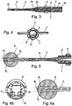
Fig. 3 is a longitudinal sectional view of the medical implement ofFigs. 1 and 2 ; -
Fig. 4 is an end view, from the proximal end, of the medical implement ofFigs. 1-3 ; -
Fig. 5 is an enlarged fragmentary view illustrating the distal end of the medical implement ofFigs. 1-4 , and particularly the manner in which the precisely spaced bores are formed in the body tissue, in this case bone tissue; -
Fig. 6a is a further enlarged view of the distal tip ofFig. 5 ; -
Fig. 6b is an end view ofFig. 6a ; and -
Fig. 7 is a flow chart illustrating the manner of using the implement ofFigs. 1-5 for applying a suture to a body tissue, such as a bone, cartilage, muscle or ligament tissue. - It is to be understood that the foregoing drawings, and the description below, are provided primarily for purposes of facilitating understanding the conceptual aspects of the invention and possible embodiments thereof, including what is presently considered to be a preferred embodiment. In the interest of clarity and brevity, no attempt is made to provide more details than necessary to enable one skilled in the art, using routine skill and design, to understand and practice the described invention. It is to be further understood that the embodiments described are for purposes of example only, and that the invention is capable of being embodied in other forms and applications than described herein, in accordance with the appended claims.
- As indicated earlier, the invention is particularly useful as a medical implement for piercing a body tissue with two precisely-spaced bores for the application of a suture to the body tissue. In such use of the apparatus, the entry ends of the two bores must be precisely spaced from each other a predetermined distance, and the exit ends of the two bores from the body must be precisely spaced a predetermined larger distance than that of the entry ends, to provide a larger area of surface contact with the suture when passed through the entry end of one bore, around the exit ends of the two bores, and then back through the entry end of the other bore. The drawings thus illustrate a medical implement particularly useful in such a medical procedure, but it will be appreciated that the invention could also be used in non-medical applications requiring the formation of two bores precisely spaced from each other, e.g. for receiving a wire or the like.
- As shown in
Figs. 1-5 of the drawings, the illustrated medical implement includes ahandle 2 having aproximal end 2a for manual grasping by a user, and adistal end 2b; and ashaft 3 having aproximal end 3a connected to thedistal end 2b ofhandle 2, and adistal end 3b. Thedistal end 3b defines a first jaw for engaging one side of the body to be pierced, shown inFig. 5 as a bone B. - The illustrated medical implement further includes an
elongated member 4, such as a rigid rod or strip, axially moveable with respect toshaft 3 andhandle 2. Elongatedmember 4 has aproximal end 4a located withinhandle 2, and adistal end 4b formed with a hook formation to define a moveable jaw cooperable with the fixed jaw at thedistal end 3b ofshaft 3, to grasp the body member to be pierced, as will be described more particularly below. - The proximal end of
elongated member 4 is coupled to a finger-piece 5 moveable within aslot 2c inhandle 2, in order to movejaw 4b towards or away from the fixedjaw 3b. Thedistal end 2b ofhandle 2 is formed with external threads in order to threadedly receive anut 6 which may be rotated in order to engage and retain finger-piece 5 in its position. - As shown particularly in
Figs. 3 and 4 ,handle 2 andshaft 3 are formed with a pair ofchannels proximal end 2a ofhandle 2 through thedistal end 3b of theshaft 3. The twochannels distal end 2b of the handle, cross each other at across-over point 9 in an intermediate portion ofshaft 3, and then diverge from each other at their exit ends at thedistal end 3b ofshaft 3. - As will be described more particularly below,
channels jaw 3b at the distal end ofshaft 3, andmoveable jaw 4b ofelongated member 4, with two precisely located bores. Thus, as shown inFigs. 5 and 6a , the tissue involved is a bone B and is pierced by two bores B1, B2 which diverge away from each other from the entry end (right end,Fig. 5 ) of the bores, to the exit end (left end,Fig. 5 ) of the bores, such that the entry ends are spaced a predetermined distance from each other, and the exit ends are spaced a predetermined larger distance from each other. The latter spacing is particularly important to provide better support for a suture to be passed through the bores. - It will be appreciated that the spacings of the two bores may be precisely determined as desired for any particularly application by appropriately designing the angle and dimensions of the two
channels handle 2 andshaft 3. - As will be further described below, the two
channels Fig. 4 . - The exemplary method, not forming part of the invention, of using the implement of
Figs. 1-5 for producing the two precisely-spaced bores B1, B2 (Fig. 5 ) through the body tissue (B), and also for applying a suture through the so-produced bores, is now described particularly with respect to the flowchart ofFig. 7 . - Thus, as shown in the flowchart of
Fig. 7 ,moveable jaw 4b of the implement is moved to its open position, shown inFigs. 2 and3 , by moving finger-piece 5 in the distal direction inslot 2c of thehandle 2, preceded by threadingnut 6 towards the distal end ofhandle 2 to retain the finger-piece in place (block 11,Fig. 7 ). - The implement is then applied to the body tissue, e.g. bone B
Fig. 5 , to be pierced (block 12); andjaw 4b is then closed by threadingnut 6 towards the proximal end ofhandle 8 and moving hand-piece 5 against the nut, such that the bone B is grasped between the two jaws (block 13). - Channel 7 through
handle 2 is then used for guiding a medical piercing instrument, e.g. a drill, trocar, wire or needle, to pierce the body tissue (e.g., bone B) with the first bore B1Fig. 5 (block 14); and thenchannel 8 is used in the same manner for guiding the piercing instrument to pierce the body tissue with the second bore B2 (block 15). - The suture (not illustrated) is then passed, via
channel 7, through bore B1 through the exit (left) end of the bore B1, and then through the exit end of bore B2, and finally throughchannel 8 to the proximal end of handle 2 (block 16) such that the two ends of the suture are accessible to the surgeon for typing purposes. - Various known procedures may be used, such as by using suture leaders, suture manipulators, shuttles, or other suturing instruments for leading the suture through the body tissue via
channel 7, and retrieving the suture from the body tissue viachannel 8. As indicated earlier,slot 9 connecting the two channels together facilitates the foregoing movements of the suture. - While the invention has been described with respect to one preferred embodiment, it will be appreciated that this is set forth merely for purposes of example, and that many variations may be made. For example,
shaft 3 may be formed with rectangular cuts or flues communicating with the bores for cleaning burns and sharp edges created when drilling the bores, or for removing debris when the implement is to be reusable. Disposable, single-use implement, e.g., made from plastics, would not require such flues. - Many other variations, modifications and applications of the invention will be apparent to those skilled in the art, in accordance with the appended claims.
Claims (13)
- A medical implement for use in piercing a body tissue with first and second bores having entry ends into the body tissue precisely spaced from each other a predetermined distance, and exit ends from the body tissue precisely spaced from each other a predetermined larger distance than that of the entry ends, comprising:a handle (2) having a proximal end (2a) for manual grasping by a user, and a distal end (2b);a shaft (3) having a proximal end (3a) connected to said distal end of the handle, and a distal end (3b) defining a first jaw for engaging one side of the body tissue to be pierced;and a second jaw (4b) moveable towards said first jaw for engaging the opposite side of the body tissue to be pierced, and for clamping the body tissue between the two jaws;characterized in that said handle and shaft are formed with a pair of channels (7,8) extending from the proximal end of the handle through the distal end of the shaft;said pair of channels converging toward each other to a cross-over point (9), and then diverging away from each other where exiting at the distal end of the shaft;said pair of channels being dimensioned to enable a medical piercing instrument to be passed first through one of said channels to pierce the body tissue (B) with said first bore (B1) when the body tissue is clamped between the jaws, and then through the other of said channels to pierce the body tissue with said second bore (B2) spaced from said first bore said predetermined distance at the entry ends of the two bores, and said predetermined larger distance at the exit ends of the two bores; said larger distance at the exit ends providing support for a suture being passed through said bores.
- The medical implement according to Claim 1, wherein said channels (7,8) through said handle are interconnected by a slot.
- The medical implement according to Claim 1, wherein said implement is a medical implement for use in piercing body tissue, and said pair of channels (7,8) are dimensioned to guide a medical piercing instrument through them.
- The medical implement according to Claim 3, wherein said pair of channels (7,8) are dimensioned first to guide a drill, trocar, wire, or needle therethrough, and then a suture therethrough.
- The medical implement according to Claim 3, wherein said first and second jaws are dimensioned to grasp bone tissue between them for piercing same with said first and second bores in order to receive a suture therethrough.
- The medical implement according to Claim 3, wherein said first and second jaws are dimensioned to grasp cartilage, muscle, tendon or ligament tissue between the jaws for piercing same with said first and second bores in order to receive a suture therethrough.
- The medical implement according to Claim 1, wherein said proximal end of the handle (2a) includes a finger-piece coupled to said second jaw (4b) for moving said second jaw towards and away from said first jaw.
- The medical implement according to Claim 7, wherein said finger-piece is slidably moveable along said handle (2) and is coupled to said second jaw (4b) via an axial slit formed in said handle.
- The medical implement according to Claim 8, wherein said handle (2) further includes a threaded section on the distal side of said finger-piece threadedly receiving a nut for retaining the finger-piece in its moved position.
- The medical implement according to Claim 1, wherein said second jaw (4b) is in the form of a hooked end of an elongated member moveable axially with respect to said shaft (3) and handle (2).
- The medical implement according to Claim 1, wherein said cross over point (9) is dimensioned to enable the advancement of a suture therethrough.
- The medical implement according to Claim 1, wherein said second jaw (4b) is positioned between said exit ends of said bores.
- The medical implement according to Claim 1, wherein said cross over point (9) is positioned at an intermediate portion of said shaft (3).
Applications Claiming Priority (2)
| Application Number | Priority Date | Filing Date | Title |
|---|---|---|---|
| US92473807P | 2007-05-30 | 2007-05-30 | |
| PCT/IL2008/000731 WO2008146291A2 (en) | 2007-05-30 | 2008-05-29 | Piercing implement particularly useful as a medical implement for piercing body tissue, and method of using such implement for applying a suture to the body tissue |
Publications (3)
| Publication Number | Publication Date |
|---|---|
| EP2157924A2 EP2157924A2 (en) | 2010-03-03 |
| EP2157924A4 EP2157924A4 (en) | 2014-08-27 |
| EP2157924B1 true EP2157924B1 (en) | 2019-11-06 |
Family
ID=40075635
Family Applications (1)
| Application Number | Title | Priority Date | Filing Date |
|---|---|---|---|
| EP08751410.5A Active EP2157924B1 (en) | 2007-05-30 | 2008-05-29 | Piercing implement particularly useful as a medical implement for piercing body tissue |
Country Status (5)
| Country | Link |
|---|---|
| US (1) | US8672954B2 (en) |
| EP (1) | EP2157924B1 (en) |
| JP (1) | JP2010527733A (en) |
| CA (1) | CA2687935C (en) |
| WO (1) | WO2008146291A2 (en) |
Families Citing this family (30)
| Publication number | Priority date | Publication date | Assignee | Title |
|---|---|---|---|---|
| US8617219B2 (en) | 2006-07-31 | 2013-12-31 | T.A.G. Medical Devices—Agriculture Cooperative Ltd. | Arthroscopic bone transplanting procedure, and medical instruments useful therein |
| WO2008146291A2 (en) | 2007-05-30 | 2008-12-04 | T.A.G. Medical Products A Limited Partnership | Piercing implement particularly useful as a medical implement for piercing body tissue, and method of using such implement for applying a suture to the body tissue |
| US8663253B2 (en) | 2007-07-03 | 2014-03-04 | Ceterix Orthopaedics, Inc. | Methods of meniscus repair |
| US9861354B2 (en) | 2011-05-06 | 2018-01-09 | Ceterix Orthopaedics, Inc. | Meniscus repair |
| US8465505B2 (en) | 2011-05-06 | 2013-06-18 | Ceterix Orthopaedics, Inc. | Suture passer devices and methods |
| EP2211725A4 (en) | 2007-11-05 | 2015-04-01 | Ceterix Orthopedics Inc | Suture passing instrument and method |
| US11744575B2 (en) | 2009-11-09 | 2023-09-05 | Ceterix Orthopaedics, Inc. | Suture passer devices and methods |
| US9011454B2 (en) | 2009-11-09 | 2015-04-21 | Ceterix Orthopaedics, Inc. | Suture passer with radiused upper jaw |
| JP5719374B2 (en) | 2009-11-09 | 2015-05-20 | セテリックス オーソピーディクス インコーポレイテッド | Device, system, and method for repairing a meniscus |
| US9357997B2 (en) | 2011-07-08 | 2016-06-07 | Smith & Nephew, Inc. | Suture passer and method |
| US8888849B2 (en) | 2011-07-08 | 2014-11-18 | Smith & Nephew, Inc. | Soft tissue repair |
| US8951263B2 (en) | 2011-07-08 | 2015-02-10 | Smith & Nephew, Inc. | Orthopedic suture passer and method |
| US8882834B2 (en) | 2011-07-08 | 2014-11-11 | Smith & Nephew, Inc. | Soft tissue repair |
| US9662105B2 (en) | 2011-07-08 | 2017-05-30 | Smith & Nephew, Inc. | Suture passer and method |
| US8801727B2 (en) | 2011-07-08 | 2014-08-12 | Smith & Nephew, Inc. | Orthopedic suture passer and method |
| US20130123809A1 (en) | 2011-11-11 | 2013-05-16 | VentureMD Innovations, LLC | Transosseous attachment instruments |
| US10470756B2 (en) | 2011-11-16 | 2019-11-12 | VentureMD Innovations, LLC | Suture anchor and method |
| US10548585B2 (en) | 2011-11-16 | 2020-02-04 | VentureMD Innovations, LLC | Soft tissue attachment |
| US10136883B2 (en) | 2011-11-16 | 2018-11-27 | VentureMD Innovations, LLC | Method of anchoring a suture |
| US10675014B2 (en) | 2011-11-16 | 2020-06-09 | Crossroads Extremity Systems, Llc | Knotless soft tissue attachment |
| US9687221B2 (en) | 2013-02-13 | 2017-06-27 | Venture MD Innovations, LLC | Method of anchoring a suture |
| US10820918B2 (en) | 2015-07-17 | 2020-11-03 | Crossroads Extremity Systems, Llc | Transosseous guide and method |
| US9962174B2 (en) | 2015-07-17 | 2018-05-08 | Kator, Llc | Transosseous method |
| US10154868B2 (en) | 2015-07-17 | 2018-12-18 | Kator, Llc | Transosseous method |
| US10226243B2 (en) | 2015-08-04 | 2019-03-12 | Kator, Llc | Transosseous suture anchor |
| US12383253B2 (en) | 2015-08-04 | 2025-08-12 | Crossroads Extremity Systems, Llc | Suture anchor |
| US12295556B2 (en) | 2019-09-27 | 2025-05-13 | Merit Medical Systems, Inc. | Rotation biopsy system and handle |
| US12150627B2 (en) | 2019-12-11 | 2024-11-26 | Merit Medical Systems, Inc. | Bone biopsy device and related methods |
| CN113081220B (en) * | 2021-03-22 | 2022-07-29 | 宁波大学医学院附属医院 | Meniscus threading device |
| WO2025141577A1 (en) * | 2023-12-27 | 2025-07-03 | T.A.G. Medical Products Corporation Ltd. | System and method for forming a bore in a bone and inserting at least one anchor |
Family Cites Families (24)
| Publication number | Priority date | Publication date | Assignee | Title |
|---|---|---|---|---|
| FR2560764B1 (en) | 1984-03-09 | 1988-05-13 | Matco | DAVIER FOR FRACTURE REDUCTION |
| US5637112A (en) | 1992-06-08 | 1997-06-10 | Orthopedic Systems, Inc. | Apparatus for attaching suture to bone |
| IL109929A (en) | 1994-06-08 | 1998-04-05 | Gotfried Yehiel | Surgical instrument for use during connection of a fractured bone |
| US5697932A (en) | 1994-11-09 | 1997-12-16 | Osteonics Corp. | Bone graft delivery system and method |
| SE506404C2 (en) | 1994-11-22 | 1997-12-15 | Lars Johan Henrik Hansson | Control instruments intended for fixing bone fragments in case of bone fracture |
| US5584839A (en) * | 1994-12-12 | 1996-12-17 | Gieringer; Robert E. | Intraarticular drill guide and arthroscopic methods |
| US5562686A (en) * | 1995-04-19 | 1996-10-08 | United States Surgical Corporation | Apparaus and method for suturing body tissue |
| JPH0975366A (en) * | 1995-09-12 | 1997-03-25 | M Ii Syst:Kk | Guide for drilling collum femoris part |
| RU2087133C1 (en) | 1996-01-11 | 1997-08-20 | Гуськов Игорь Алексеевич | Method for treating femoral neck fractures |
| JP3611934B2 (en) | 1996-10-23 | 2005-01-19 | メイラ株式会社 | Bone drilling device for ligament reconstruction |
| US5993466A (en) * | 1997-06-17 | 1999-11-30 | Yoon; Inbae | Suturing instrument with multiple rotatably mounted spreadable needle holders |
| CA2238117C (en) | 1997-05-30 | 2006-01-10 | United States Surgical Corporation | Method and instrumentation for implant insertion |
| DE29805703U1 (en) | 1998-03-28 | 1998-08-27 | Brehm, Peter, 91085 Weisendorf | Bone grasping forceps |
| ES2228037T3 (en) | 1998-04-09 | 2005-04-01 | Sdgi Holdings, Inc. | VERTEBRAL BODY SEPARATOR DEVICE. |
| JP2002102236A (en) | 2000-10-02 | 2002-04-09 | Koseki Ika Kk | Drill guide for patella |
| DE60140558D1 (en) | 2000-10-25 | 2009-12-31 | Kyphon S A R L | SYSTEMS FOR THE REPOSITION OF BROKEN BONE BY MEANS OF A CANNULA FOR THE REPONATION OF BONE FRACTURES |
| US6511487B1 (en) * | 2000-11-28 | 2003-01-28 | T. A. G. Medical Products Ltd. | Suturing instrument and method |
| US6679888B2 (en) | 2001-05-29 | 2004-01-20 | Synthes | Femur lever |
| WO2005053548A1 (en) * | 2003-12-03 | 2005-06-16 | Synthes Ag Chur | Device for repositioning bone fractures |
| DE502005002984D1 (en) * | 2005-01-24 | 2008-04-10 | Ami Gmbh | Device for the surgical closure of a trocar puncture |
| US20070005067A1 (en) * | 2005-06-21 | 2007-01-04 | Brian Dross | Arthoscopic method and apparatus for tissue attachment to bone |
| US20070073342A1 (en) * | 2005-09-27 | 2007-03-29 | Innovative Spinal Technologies | Annular access device using t-anchors |
| US8617219B2 (en) | 2006-07-31 | 2013-12-31 | T.A.G. Medical Devices—Agriculture Cooperative Ltd. | Arthroscopic bone transplanting procedure, and medical instruments useful therein |
| WO2008146291A2 (en) | 2007-05-30 | 2008-12-04 | T.A.G. Medical Products A Limited Partnership | Piercing implement particularly useful as a medical implement for piercing body tissue, and method of using such implement for applying a suture to the body tissue |
-
2008
- 2008-05-29 WO PCT/IL2008/000731 patent/WO2008146291A2/en not_active Ceased
- 2008-05-29 US US12/602,101 patent/US8672954B2/en not_active Expired - Fee Related
- 2008-05-29 CA CA2687935A patent/CA2687935C/en active Active
- 2008-05-29 EP EP08751410.5A patent/EP2157924B1/en active Active
- 2008-05-29 JP JP2010509949A patent/JP2010527733A/en active Pending
Non-Patent Citations (1)
| Title |
|---|
| None * |
Also Published As
| Publication number | Publication date |
|---|---|
| US8672954B2 (en) | 2014-03-18 |
| JP2010527733A (en) | 2010-08-19 |
| WO2008146291A2 (en) | 2008-12-04 |
| CA2687935A1 (en) | 2008-12-04 |
| WO2008146291A3 (en) | 2010-02-25 |
| EP2157924A4 (en) | 2014-08-27 |
| US20100249806A1 (en) | 2010-09-30 |
| CA2687935C (en) | 2015-06-23 |
| EP2157924A2 (en) | 2010-03-03 |
Similar Documents
| Publication | Publication Date | Title |
|---|---|---|
| CA2687935C (en) | Piercing implement particularly useful as a medical implement for piercing body tissue, and method of using such implement for applying a suture to the body tissue | |
| US11559296B2 (en) | Medical apparatus and method for attaching a suture to a bone | |
| US9358001B2 (en) | Advance suture passer | |
| US8709022B2 (en) | Method and apparatus for passing a suture | |
| US8663251B2 (en) | In-line suture passer and method of passing suture | |
| US6511487B1 (en) | Suturing instrument and method | |
| EP3025654B1 (en) | Medical implement for manipulating sutures particularly useful in arthroscopic surgery | |
| EP0315371B1 (en) | A suturing instrument for use in arthroscopic surgery | |
| EP3150130B1 (en) | Apparatus for guiding a suture thread | |
| EP3481307B1 (en) | Suture passer/retriever | |
| JP2010527733A5 (en) | ||
| US9775596B2 (en) | Device for anchoring a suture | |
| CN101631503B (en) | Shape memory filaments for suture processing | |
| US20090281578A1 (en) | Proximal humeral fracture reduction and fixation device | |
| CN101193598A (en) | Surgical closure devices and methods | |
| US9615822B2 (en) | Insertion tools and method for soft anchor | |
| JP6887329B2 (en) | Bone reduction forceps | |
| CN113520497A (en) | Endoscopic stitching device for one-handed operation | |
| DE102016122543A1 (en) | Surgical rod element and instrument set for the minimally invasive execution of a single suture | |
| EP2983594B1 (en) | Surgical suture passer | |
| AU2015255260B2 (en) | Medical Apparatus and Method for Attaching a Suture to a Bone | |
| CN118058816A (en) | Patellar fracture closed reduction and internal fixation surgical kit and use method thereof | |
| WO2022077004A1 (en) | Arthroscopic surgical tool for manipulating bony tissue |
Legal Events
| Date | Code | Title | Description |
|---|---|---|---|
| PUAI | Public reference made under article 153(3) epc to a published international application that has entered the european phase |
Free format text: ORIGINAL CODE: 0009012 |
|
| 17P | Request for examination filed |
Effective date: 20091223 |
|
| AK | Designated contracting states |
Kind code of ref document: A2 Designated state(s): AT BE BG CH CY CZ DE DK EE ES FI FR GB GR HR HU IE IS IT LI LT LU LV MC MT NL NO PL PT RO SE SI SK TR |
|
| AX | Request for extension of the european patent |
Extension state: AL BA MK RS |
|
| R17D | Deferred search report published (corrected) |
Effective date: 20100225 |
|
| DAX | Request for extension of the european patent (deleted) | ||
| RAP1 | Party data changed (applicant data changed or rights of an application transferred) |
Owner name: T.A.G. MEDICAL DEVICES - AGRICULTURE COOPERATIVE L |
|
| A4 | Supplementary search report drawn up and despatched |
Effective date: 20140729 |
|
| RIC1 | Information provided on ipc code assigned before grant |
Ipc: A61B 17/295 20060101ALN20140723BHEP Ipc: A61B 17/17 20060101ALN20140723BHEP Ipc: A61B 17/34 20060101AFI20140723BHEP Ipc: A61B 17/04 20060101ALI20140723BHEP Ipc: A61B 17/29 20060101ALN20140723BHEP |
|
| REG | Reference to a national code |
Ref country code: DE Ref legal event code: R079 Ref document number: 602008061575 Country of ref document: DE Free format text: PREVIOUS MAIN CLASS: A61B0017340000 Ipc: A61B0017295000 |
|
| GRAP | Despatch of communication of intention to grant a patent |
Free format text: ORIGINAL CODE: EPIDOSNIGR1 |
|
| STAA | Information on the status of an ep patent application or granted ep patent |
Free format text: STATUS: GRANT OF PATENT IS INTENDED |
|
| RIC1 | Information provided on ipc code assigned before grant |
Ipc: A61B 17/04 20060101ALI20190613BHEP Ipc: A61B 17/295 20060101AFI20190613BHEP |
|
| INTG | Intention to grant announced |
Effective date: 20190704 |
|
| GRAS | Grant fee paid |
Free format text: ORIGINAL CODE: EPIDOSNIGR3 |
|
| GRAA | (expected) grant |
Free format text: ORIGINAL CODE: 0009210 |
|
| STAA | Information on the status of an ep patent application or granted ep patent |
Free format text: STATUS: THE PATENT HAS BEEN GRANTED |
|
| RIN1 | Information on inventor provided before grant (corrected) |
Inventor name: MOOR, DAN Inventor name: NAHMIAS, SHAI Inventor name: LAFOSSE, LAURENT Inventor name: OREN, RAN |
|
| AK | Designated contracting states |
Kind code of ref document: B1 Designated state(s): AT BE BG CH CY CZ DE DK EE ES FI FR GB GR HR HU IE IS IT LI LT LU LV MC MT NL NO PL PT RO SE SI SK TR |
|
| REG | Reference to a national code |
Ref country code: GB Ref legal event code: FG4D |
|
| REG | Reference to a national code |
Ref country code: AT Ref legal event code: REF Ref document number: 1197708 Country of ref document: AT Kind code of ref document: T Effective date: 20191115 Ref country code: CH Ref legal event code: EP |
|
| REG | Reference to a national code |
Ref country code: IE Ref legal event code: FG4D |
|
| REG | Reference to a national code |
Ref country code: DE Ref legal event code: R096 Ref document number: 602008061575 Country of ref document: DE |
|
| REG | Reference to a national code |
Ref country code: CH Ref legal event code: NV Representative=s name: DENNEMEYER AG, CH |
|
| REG | Reference to a national code |
Ref country code: NL Ref legal event code: MP Effective date: 20191106 |
|
| REG | Reference to a national code |
Ref country code: LT Ref legal event code: MG4D |
|
| PG25 | Lapsed in a contracting state [announced via postgrant information from national office to epo] |
Ref country code: PL Free format text: LAPSE BECAUSE OF FAILURE TO SUBMIT A TRANSLATION OF THE DESCRIPTION OR TO PAY THE FEE WITHIN THE PRESCRIBED TIME-LIMIT Effective date: 20191106 Ref country code: LV Free format text: LAPSE BECAUSE OF FAILURE TO SUBMIT A TRANSLATION OF THE DESCRIPTION OR TO PAY THE FEE WITHIN THE PRESCRIBED TIME-LIMIT Effective date: 20191106 Ref country code: SE Free format text: LAPSE BECAUSE OF FAILURE TO SUBMIT A TRANSLATION OF THE DESCRIPTION OR TO PAY THE FEE WITHIN THE PRESCRIBED TIME-LIMIT Effective date: 20191106 Ref country code: LT Free format text: LAPSE BECAUSE OF FAILURE TO SUBMIT A TRANSLATION OF THE DESCRIPTION OR TO PAY THE FEE WITHIN THE PRESCRIBED TIME-LIMIT Effective date: 20191106 Ref country code: FI Free format text: LAPSE BECAUSE OF FAILURE TO SUBMIT A TRANSLATION OF THE DESCRIPTION OR TO PAY THE FEE WITHIN THE PRESCRIBED TIME-LIMIT Effective date: 20191106 Ref country code: BG Free format text: LAPSE BECAUSE OF FAILURE TO SUBMIT A TRANSLATION OF THE DESCRIPTION OR TO PAY THE FEE WITHIN THE PRESCRIBED TIME-LIMIT Effective date: 20200206 Ref country code: GR Free format text: LAPSE BECAUSE OF FAILURE TO SUBMIT A TRANSLATION OF THE DESCRIPTION OR TO PAY THE FEE WITHIN THE PRESCRIBED TIME-LIMIT Effective date: 20200207 Ref country code: NO Free format text: LAPSE BECAUSE OF FAILURE TO SUBMIT A TRANSLATION OF THE DESCRIPTION OR TO PAY THE FEE WITHIN THE PRESCRIBED TIME-LIMIT Effective date: 20200206 Ref country code: NL Free format text: LAPSE BECAUSE OF FAILURE TO SUBMIT A TRANSLATION OF THE DESCRIPTION OR TO PAY THE FEE WITHIN THE PRESCRIBED TIME-LIMIT Effective date: 20191106 Ref country code: ES Free format text: LAPSE BECAUSE OF FAILURE TO SUBMIT A TRANSLATION OF THE DESCRIPTION OR TO PAY THE FEE WITHIN THE PRESCRIBED TIME-LIMIT Effective date: 20191106 Ref country code: PT Free format text: LAPSE BECAUSE OF FAILURE TO SUBMIT A TRANSLATION OF THE DESCRIPTION OR TO PAY THE FEE WITHIN THE PRESCRIBED TIME-LIMIT Effective date: 20200306 |
|
| PG25 | Lapsed in a contracting state [announced via postgrant information from national office to epo] |
Ref country code: IS Free format text: LAPSE BECAUSE OF FAILURE TO SUBMIT A TRANSLATION OF THE DESCRIPTION OR TO PAY THE FEE WITHIN THE PRESCRIBED TIME-LIMIT Effective date: 20200306 Ref country code: HR Free format text: LAPSE BECAUSE OF FAILURE TO SUBMIT A TRANSLATION OF THE DESCRIPTION OR TO PAY THE FEE WITHIN THE PRESCRIBED TIME-LIMIT Effective date: 20191106 |
|
| PG25 | Lapsed in a contracting state [announced via postgrant information from national office to epo] |
Ref country code: EE Free format text: LAPSE BECAUSE OF FAILURE TO SUBMIT A TRANSLATION OF THE DESCRIPTION OR TO PAY THE FEE WITHIN THE PRESCRIBED TIME-LIMIT Effective date: 20191106 Ref country code: DK Free format text: LAPSE BECAUSE OF FAILURE TO SUBMIT A TRANSLATION OF THE DESCRIPTION OR TO PAY THE FEE WITHIN THE PRESCRIBED TIME-LIMIT Effective date: 20191106 Ref country code: CZ Free format text: LAPSE BECAUSE OF FAILURE TO SUBMIT A TRANSLATION OF THE DESCRIPTION OR TO PAY THE FEE WITHIN THE PRESCRIBED TIME-LIMIT Effective date: 20191106 Ref country code: RO Free format text: LAPSE BECAUSE OF FAILURE TO SUBMIT A TRANSLATION OF THE DESCRIPTION OR TO PAY THE FEE WITHIN THE PRESCRIBED TIME-LIMIT Effective date: 20191106 |
|
| REG | Reference to a national code |
Ref country code: DE Ref legal event code: R097 Ref document number: 602008061575 Country of ref document: DE |
|
| REG | Reference to a national code |
Ref country code: AT Ref legal event code: MK05 Ref document number: 1197708 Country of ref document: AT Kind code of ref document: T Effective date: 20191106 |
|
| PG25 | Lapsed in a contracting state [announced via postgrant information from national office to epo] |
Ref country code: SK Free format text: LAPSE BECAUSE OF FAILURE TO SUBMIT A TRANSLATION OF THE DESCRIPTION OR TO PAY THE FEE WITHIN THE PRESCRIBED TIME-LIMIT Effective date: 20191106 |
|
| PLBE | No opposition filed within time limit |
Free format text: ORIGINAL CODE: 0009261 |
|
| STAA | Information on the status of an ep patent application or granted ep patent |
Free format text: STATUS: NO OPPOSITION FILED WITHIN TIME LIMIT |
|
| 26N | No opposition filed |
Effective date: 20200807 |
|
| PG25 | Lapsed in a contracting state [announced via postgrant information from national office to epo] |
Ref country code: AT Free format text: LAPSE BECAUSE OF FAILURE TO SUBMIT A TRANSLATION OF THE DESCRIPTION OR TO PAY THE FEE WITHIN THE PRESCRIBED TIME-LIMIT Effective date: 20191106 Ref country code: SI Free format text: LAPSE BECAUSE OF FAILURE TO SUBMIT A TRANSLATION OF THE DESCRIPTION OR TO PAY THE FEE WITHIN THE PRESCRIBED TIME-LIMIT Effective date: 20191106 |
|
| PG25 | Lapsed in a contracting state [announced via postgrant information from national office to epo] |
Ref country code: MC Free format text: LAPSE BECAUSE OF FAILURE TO SUBMIT A TRANSLATION OF THE DESCRIPTION OR TO PAY THE FEE WITHIN THE PRESCRIBED TIME-LIMIT Effective date: 20191106 |
|
| REG | Reference to a national code |
Ref country code: BE Ref legal event code: MM Effective date: 20200531 |
|
| GBPC | Gb: european patent ceased through non-payment of renewal fee |
Effective date: 20200529 |
|
| PG25 | Lapsed in a contracting state [announced via postgrant information from national office to epo] |
Ref country code: LU Free format text: LAPSE BECAUSE OF NON-PAYMENT OF DUE FEES Effective date: 20200529 |
|
| PG25 | Lapsed in a contracting state [announced via postgrant information from national office to epo] |
Ref country code: GB Free format text: LAPSE BECAUSE OF NON-PAYMENT OF DUE FEES Effective date: 20200529 Ref country code: IE Free format text: LAPSE BECAUSE OF NON-PAYMENT OF DUE FEES Effective date: 20200529 |
|
| PG25 | Lapsed in a contracting state [announced via postgrant information from national office to epo] |
Ref country code: BE Free format text: LAPSE BECAUSE OF NON-PAYMENT OF DUE FEES Effective date: 20200531 |
|
| PG25 | Lapsed in a contracting state [announced via postgrant information from national office to epo] |
Ref country code: TR Free format text: LAPSE BECAUSE OF FAILURE TO SUBMIT A TRANSLATION OF THE DESCRIPTION OR TO PAY THE FEE WITHIN THE PRESCRIBED TIME-LIMIT Effective date: 20191106 Ref country code: MT Free format text: LAPSE BECAUSE OF FAILURE TO SUBMIT A TRANSLATION OF THE DESCRIPTION OR TO PAY THE FEE WITHIN THE PRESCRIBED TIME-LIMIT Effective date: 20191106 Ref country code: CY Free format text: LAPSE BECAUSE OF FAILURE TO SUBMIT A TRANSLATION OF THE DESCRIPTION OR TO PAY THE FEE WITHIN THE PRESCRIBED TIME-LIMIT Effective date: 20191106 |
|
| P01 | Opt-out of the competence of the unified patent court (upc) registered |
Effective date: 20230602 |
|
| PGFP | Annual fee paid to national office [announced via postgrant information from national office to epo] |
Ref country code: DE Payment date: 20250521 Year of fee payment: 18 |
|
| PGFP | Annual fee paid to national office [announced via postgrant information from national office to epo] |
Ref country code: IT Payment date: 20250527 Year of fee payment: 18 |
|
| PGFP | Annual fee paid to national office [announced via postgrant information from national office to epo] |
Ref country code: FR Payment date: 20250528 Year of fee payment: 18 |
|
| PGFP | Annual fee paid to national office [announced via postgrant information from national office to epo] |
Ref country code: CH Payment date: 20250601 Year of fee payment: 18 |