EP2157921B1 - Medical device for the treatment of the human or animal body using pressure or impact waves - Google Patents
Medical device for the treatment of the human or animal body using pressure or impact waves Download PDFInfo
- Publication number
- EP2157921B1 EP2157921B1 EP08758605.3A EP08758605A EP2157921B1 EP 2157921 B1 EP2157921 B1 EP 2157921B1 EP 08758605 A EP08758605 A EP 08758605A EP 2157921 B1 EP2157921 B1 EP 2157921B1
- Authority
- EP
- European Patent Office
- Prior art keywords
- applicator
- applicator part
- handpiece
- pressure
- gas
- Prior art date
- Legal status (The legal status is an assumption and is not a legal conclusion. Google has not performed a legal analysis and makes no representation as to the accuracy of the status listed.)
- Active
Links
Images


Classifications
-
- A—HUMAN NECESSITIES
- A61—MEDICAL OR VETERINARY SCIENCE; HYGIENE
- A61B—DIAGNOSIS; SURGERY; IDENTIFICATION
- A61B17/00—Surgical instruments, devices or methods, e.g. tourniquets
- A61B17/22—Implements for squeezing-off ulcers or the like on the inside of inner organs of the body; Implements for scraping-out cavities of body organs, e.g. bones; Calculus removers; Calculus smashing apparatus; Apparatus for removing obstructions in blood vessels, not otherwise provided for
- A61B17/22004—Implements for squeezing-off ulcers or the like on the inside of inner organs of the body; Implements for scraping-out cavities of body organs, e.g. bones; Calculus removers; Calculus smashing apparatus; Apparatus for removing obstructions in blood vessels, not otherwise provided for using mechanical vibrations, e.g. ultrasonic shock waves
-
- A—HUMAN NECESSITIES
- A61—MEDICAL OR VETERINARY SCIENCE; HYGIENE
- A61B—DIAGNOSIS; SURGERY; IDENTIFICATION
- A61B17/00—Surgical instruments, devices or methods, e.g. tourniquets
- A61B17/16—Bone cutting, breaking or removal means other than saws, e.g. Osteoclasts; Drills or chisels for bones; Trepans
- A61B17/1697—Bone cutting, breaking or removal means other than saws, e.g. Osteoclasts; Drills or chisels for bones; Trepans specially adapted for wire insertion
-
- A—HUMAN NECESSITIES
- A61—MEDICAL OR VETERINARY SCIENCE; HYGIENE
- A61B—DIAGNOSIS; SURGERY; IDENTIFICATION
- A61B17/00—Surgical instruments, devices or methods, e.g. tourniquets
- A61B17/56—Surgical instruments or methods for treatment of bones or joints; Devices specially adapted therefor
- A61B17/58—Surgical instruments or methods for treatment of bones or joints; Devices specially adapted therefor for osteosynthesis, e.g. bone plates, screws, setting implements or the like
- A61B17/88—Osteosynthesis instruments; Methods or means for implanting or extracting internal or external fixation devices
- A61B17/92—Impactors or extractors, e.g. for removing intramedullary devices
- A61B17/921—Impactors or extractors, e.g. for removing intramedullary devices for intramedullary devices
-
- A—HUMAN NECESSITIES
- A61—MEDICAL OR VETERINARY SCIENCE; HYGIENE
- A61H—PHYSICAL THERAPY APPARATUS, e.g. DEVICES FOR LOCATING OR STIMULATING REFLEX POINTS IN THE BODY; ARTIFICIAL RESPIRATION; MASSAGE; BATHING DEVICES FOR SPECIAL THERAPEUTIC OR HYGIENIC PURPOSES OR SPECIFIC PARTS OF THE BODY
- A61H23/00—Percussion or vibration massage, e.g. using supersonic vibration; Suction-vibration massage; Massage with moving diaphragms
- A61H23/008—Percussion or vibration massage, e.g. using supersonic vibration; Suction-vibration massage; Massage with moving diaphragms using shock waves
-
- A—HUMAN NECESSITIES
- A61—MEDICAL OR VETERINARY SCIENCE; HYGIENE
- A61H—PHYSICAL THERAPY APPARATUS, e.g. DEVICES FOR LOCATING OR STIMULATING REFLEX POINTS IN THE BODY; ARTIFICIAL RESPIRATION; MASSAGE; BATHING DEVICES FOR SPECIAL THERAPEUTIC OR HYGIENIC PURPOSES OR SPECIFIC PARTS OF THE BODY
- A61H23/00—Percussion or vibration massage, e.g. using supersonic vibration; Suction-vibration massage; Massage with moving diaphragms
- A61H23/02—Percussion or vibration massage, e.g. using supersonic vibration; Suction-vibration massage; Massage with moving diaphragms with electric or magnetic drive
-
- A—HUMAN NECESSITIES
- A61—MEDICAL OR VETERINARY SCIENCE; HYGIENE
- A61B—DIAGNOSIS; SURGERY; IDENTIFICATION
- A61B17/00—Surgical instruments, devices or methods, e.g. tourniquets
- A61B17/56—Surgical instruments or methods for treatment of bones or joints; Devices specially adapted therefor
- A61B17/58—Surgical instruments or methods for treatment of bones or joints; Devices specially adapted therefor for osteosynthesis, e.g. bone plates, screws, setting implements or the like
- A61B17/88—Osteosynthesis instruments; Methods or means for implanting or extracting internal or external fixation devices
- A61B17/8802—Equipment for handling bone cement or other fluid fillers
- A61B17/8847—Equipment for handling bone cement or other fluid fillers for removing cement from a bone cavity
-
- A—HUMAN NECESSITIES
- A61—MEDICAL OR VETERINARY SCIENCE; HYGIENE
- A61B—DIAGNOSIS; SURGERY; IDENTIFICATION
- A61B17/00—Surgical instruments, devices or methods, e.g. tourniquets
- A61B2017/00477—Coupling
- A61B2017/00482—Coupling with a code
-
- A—HUMAN NECESSITIES
- A61—MEDICAL OR VETERINARY SCIENCE; HYGIENE
- A61B—DIAGNOSIS; SURGERY; IDENTIFICATION
- A61B17/00—Surgical instruments, devices or methods, e.g. tourniquets
- A61B2017/00535—Surgical instruments, devices or methods, e.g. tourniquets pneumatically or hydraulically operated
- A61B2017/00544—Surgical instruments, devices or methods, e.g. tourniquets pneumatically or hydraulically operated pneumatically
-
- A—HUMAN NECESSITIES
- A61—MEDICAL OR VETERINARY SCIENCE; HYGIENE
- A61B—DIAGNOSIS; SURGERY; IDENTIFICATION
- A61B17/00—Surgical instruments, devices or methods, e.g. tourniquets
- A61B17/56—Surgical instruments or methods for treatment of bones or joints; Devices specially adapted therefor
- A61B17/58—Surgical instruments or methods for treatment of bones or joints; Devices specially adapted therefor for osteosynthesis, e.g. bone plates, screws, setting implements or the like
- A61B17/88—Osteosynthesis instruments; Methods or means for implanting or extracting internal or external fixation devices
- A61B17/92—Impactors or extractors, e.g. for removing intramedullary devices
- A61B2017/922—Devices for impaction, impact element
- A61B2017/924—Impact element driving means
Definitions
- the invention relates to a medical device for treating the human or animal body with pressure or shock waves, with a device for generating the pressure or shock waves, comprising at least one applicator and a pneumatic actuator, which by means of a pressurized gas to a proximal Occurring surface of the applicator repeatedly generates shocks to generate with the applicator part pressure or shock waves, which are coupled from the applicator via a distal exit surface in the body, wherein the applicator is movable in a housing with a limited stroke from a proximal starting position to the distal ,
- Such a device is from the document DE 197 25 477 C2 known.
- treatment of the human or animal body is, for example, the treatment of soft tissue, in particular under “Treatment of the human or animal body” in the context of the present invention, for example, the treatment of soft tissue, in particular for pain therapy, the treatment of bone tissue, the destruction of body stones, the removal of plaque in vessels, the treatment of teeth, but also the removal of bone cement or the driving in of bone nails or wires.
- the known device has, apart from the applicator part, a pneumatically accelerated impact part or projectile along an acceleration section, which repeatedly bounces on a proximal inlet surface of the applicator part to produce the pressure or shock waves in the applicator part.
- the impact of the percussion part or projectile on the stationary applicator generates pressure or shock waves in the latter, which are coupled into the body of a patient via the distal exit surface of the applicator part when the distal exit surface is placed on the body surface of the patient.
- Another medical device for treating the human or animal body with pressure or shock waves used there for the removal of bone cement is from the document WO 97/48353 A1 known. Also, this known medical device has as a device for generating the pressure or shock waves along an acceleration section pneumatically accelerated impact member or projectile, which repeatedly bounces to generate the pressure or shock waves on a proximal inlet surface of an applicator, the latter is formed there in the form of a probe, from the distal tip of the pressure or shock waves are coupled into the body.
- the design of the medical device with a device for generating the pressure or shock waves, which along an acceleration section has a reciprocating stroke part or projectile, has the disadvantage that the device is long-lasting due to the necessary acceleration distance for the impact part or projectile.
- a further disadvantage of the known device is that the impact part or projectile and / or the applicator part is subject to wear caused by the repeated impact of the projectile on the applicator part.
- a massage device which is designed in particular in the decongestant therapy for the treatment of patients with venous or lymphatic reflux disorders.
- This massage device is designed as a bandage and has at least three extending over the length parallel guided pressure transmission means made of elastic material, which are acted upon by means of controllable pressure control devices transversely to the direction of the bandage offset in time. Due to the intermittent and transversely to the direction of the bandage temporally offset application of pressure applied to the body surface of the patient pressure transmitting means arise in the tissue short pressure gradients that migrate along the extremity to be treated.
- a pressure medium a liquid or a gaseous pressure medium can be used.
- a medical device for the destruction of body stones in the urinary and bladder tract or for the destruction of plaque in vessels known, in which in the applicator part pressure or shock waves are generated by means of an electro-hydraulic transducer.
- the electrohydraulic transducer has two electrodes immersed in a fluid-filled chamber. By applying high voltage to the electrodes, sparks are generated which cause pressure or shock waves in the fluid, which then act on the proximal entrance surface of the applicator portion.
- This known device is structurally complex because of the electro-hydraulic converter.
- the invention has the object of developing a medical device of the type mentioned in such a way that the above-mentioned disadvantages are avoided, that in particular the device can be made physically small and therefore handy.
- this object is achieved by the device defined in claim 1 medical device that the pressurized gas acts in the form of individual gas pressure surges directly on the applicator to generate the pressure or shock waves.
- the pressure or shock waves with the at least one applicator part are accordingly produced by individual gas pressure pulses which act directly on the proximal inlet surface of the applicator part. Due to such a pressure or shock wave generation mechanism eliminates existing in the known device impact part or projectile and in particular the associated long acceleration distance for the impact part or projectile. The device according to the invention can thus be much smaller, especially shorter and thus be made more manageable. In addition, the device according to the invention over the known device because of the omission of the percussion part or projectile less susceptible to wear.
- the device according to the invention can be formed in an ergonomic design due to the omission of a linear acceleration section. While the known device has an elongate handpiece due to the linear acceleration path, which must be held in a less ergonomic manner in the manner of a rod in hand, the device according to the invention may comprise a handpiece in which the applicator is arranged transversely to a longitudinal direction of the handpiece , This facilitates the handling of the device in the application of pressure or shock waves in a patient.
- Another advantage of the device according to the invention is that the applicator can be subjected to shocks with a higher pulse frequency, while the pulse frequency in the known device is limited by the acceleration of the projectile part.
- the applicator is mounted with a limited stroke distally movable in the housing.
- the deflection of the applicator part with limited stroke has a massaging effect, in particular in the context of pain therapy and soft tissue treatment, in addition to the pressure or shock waves, which further improves the therapeutic effect of the device.
- the applicator is mounted gas-tight in the housing.
- the advantage of this measure is that the individual gas pressure surges act on the applicator part essentially without pressure loss, so that the entire energy of the gas pressure surges can be used to generate the pressure or shock waves in the applicator part.
- the applicator part is resiliently biased into the proximal starting position.
- the individual gas pressure surges act on the applicator part, which rests in its proximal starting position, the individual gas pressure surges causing the applicator part to be moved distally with the limited stroke, after which the applicator part is elastically moved back into its proximal starting position.
- vibrations of the applicator can be generated, which are also coupled into the body of the patient and act therapeutically.
- the return movement of the applicator can also be active, for example, with compressed air done.
- the stroke of the applicator is less than 10 mm, preferably less than 5 mm.
- the proximal entry surface of the applicator part, on which the gas pressure surges act is at least 0.5 cm 2 , preferably at least 1 cm 2 .
- the proximal inlet surface of the applicator is sufficiently large area in order to achieve by means of the gas pressure surges a large force at low amplitude of the gas pressure surges, whereby the pneumatic drive can operate at low pressure, which increases the reliability of the device according to the invention.
- the entry surface can also be as large as the exit surface or larger than this, in order to achieve particularly powerful shocks with the applicator.
- the applicator is made of a material of low specific weight, for example made of a light metal, plastic or wood.
- the execution of the at least one applicator part made of a material of low specific weight results in a given amplitude of the gas pressure surges at a high speed of the applicator and in particular also allows an even higher pulse frequency with which the gas pressure surges can be applied to the applicator.
- the applicator can in particular be made of wood, because the applicator can be made of a less impact resistant material such as wood because of the lack of a projectile or impact part that bounces on the applicator.
- An applicator part made of wood has the advantage that wood is a skin-friendly natural material and especially warm when touchdown on the body surface because of the lower heat conduction and heat capacity of wood.
- the applicator part can also be made of several materials.
- the gas pressure surges are controlled by at least one valve.
- the gas pressure surges can be generated positively controlled.
- the frequency, the amplitude and / or the duration of the gas pressure surges can be defined defined and also changed. Depending on the application, the effect of the pressure or shock waves on the area of the body to be treated can thus be optimized.
- the at least one valve is a solenoid valve.
- a solenoid valve can be opened and closed advantageously with very short switching times, which in particular high pulse frequencies of the gas pressure surges can be achieved, which can significantly exceed 30 Hz.
- the device has a handpiece which has the at least one applicator part.
- the handpiece can be configured in an ergonomically optimized shape, in particular small-sized, which makes the handling of the handpiece more ergonomic in the application of the pressure or shock waves in a patient.
- the handpiece has a mass of less than 700 g.
- the handpiece allows a low-fatigue handling.
- the ratio of mass of the handpiece and mass of the applicator is greater than 25: 1, preferably greater than 50: 1.
- the use of a low mass applicator part compared to the mass of the handpiece has the advantage that the handpiece is not or only slightly vibrated or vibrated during operation of the device, thereby further improving the handling ease of the handpiece.
- the handpiece is connectable to a control device, wherein a plurality of handpieces is provided, wherein the control unit recognizes with which handpiece the control unit is connected.
- a plurality of different handpieces are provided, each having an applicator of different design. If one of these handpieces is connected to the control unit, the control unit automatically recognizes by means of a recognition circuit, with which handpiece the control unit is connected and can then preset certain parameter ranges such as frequency, amplitude and / or duration of the gas pressure surges. Preferably, these preset parameters can be changed during operation of the device to achieve an optimal effect of pressure or shock waves on the body area.
- the at least one valve is arranged in the handpiece.
- This measure has the advantage that less gas is needed for the drive, and thus smaller gas pressure sources can be used.
- This measure is also advantageous with the aforementioned measure, according to which several different handpieces are provided.
- these different handpieces can also be designed with different valves in order to be able to optimally adapt the respective handpiece to the frequency, amplitude and / or duration of the gas pressure surges in accordance with its application purpose.
- the frequency, the amplitude and / or the duration of the gas pressure surges is / are adjustable.
- the frequency, the amplitude and / or the pressure on the handpiece is / are adjustable.
- the applicator part is exchangeable.
- This measure is particularly advantageous if only one handpiece is provided, which can be mounted on the handpiece by the interchangeability of the applicator each one optimal for the treatment treatment applicator.
- a plurality of applicator parts are provided which differ in terms of size, mass, material, shape of the distal exit surface and / or size of the distal exit surface.
- the optimal for the respective treatment applicator can be selected.
- the exit surface of the applicator part has a shape that has different dimensions in different directions transverse to the longitudinal direction.
- Applikatorteil Structure is of different sizes, which also different effects of pressure or shock waves in the body area to be treated can be achieved.
- the exit surface may be, for example, oval or elliptical.
- the exit surface of the applicator can also be round and have a convex curvature.
- the device is sound-damped.
- the advantage of this measure is that the device according to the invention is quiet in operation and the treatment is not affected by loud noises.
- a trigger element for triggering the individual gas pressure surges for individual operation and / or continuous operation is arranged on the handpiece.
- the gas pressure can then be permanently present and only on actuation of the trigger, the individual gas pressure surges are generated.
- FIGS. 1 to 3 is provided with the general reference numeral 10 medical device for treating the human or animal body with pressure or shock waves.
- the device 10 is used in particular for pain therapy or generally for the treatment of biological tissue in the body of a patient.
- the device 10 has a handpiece 12, which has a compact design, in particular is designed substantially L-shaped.
- the handpiece 12 has a housing 14, which is formed in the embodiment shown by a housing main part 16 and a housing cover 18, wherein the housing cover 18 is detachably connected to the housing main part 16.
- a screw receptacle 20 and in the housing main part 16 a threaded bore 22 is provided so that the housing cover 18 can be screwed to the housing main body 16.
- the device 10 further comprises a device for generating pressure or shock waves, which will be described in more detail below.
- the device for generating the pressure or shock waves initially has an applicator part 24 which is mounted in the housing 14, more precisely in the housing main part 16.
- an applicator holding head 26 is provided, which is screwed to a thread extension 28 of the housing main part 16.
- the applicator holding head 26 is conically formed on the outside.
- the applicator portion 24 is movable distally within the handpiece 12 and the housing 14, respectively, with the applicator holding head 26 with a limited stroke in the direction of an arrow 32, the applicator portion 24 in FIG FIG. 3 is shown in its proximal starting position.
- the applicator part 24 is resiliently biased via a return element 34 in the proximal starting position.
- the return element 34 is formed in the embodiment shown as a bellows-like spring.
- the stroke of the applicator 24 is less than 10 mm, preferably less than 5 mm.
- the device for generating the pressure or shock waves further comprises a pneumatic drive, which will be described in more detail below.
- the pneumatic drive uses a pressurized gas that exerts shocks in the form of individual gas pressure surges on the applicator 24 for generating the pressure or shock waves in the applicator 24.
- the individual gas pressure surges act directly on the applicator part 24, namely on a proximal inlet surface 36 of the applicator 24.
- a gas supply channel 38 In the immediate vicinity of the proximal inlet surface 36 opens a gas supply channel 38 through which the individual gas pressure shocks are directed to the proximal inlet surface 36 of the applicator 24.
- the proximal entrance surface 36 of the applicator part 24 has a large surface area, for example has an area of at least 0.5 cm 2 , preferably of at least 1 cm 2 . While the gas supply channel 38 according to FIG. 3 In contrast, at a distance from the entrance surface 36 has a cross section which is smaller than the entrance surface 36, the gas supply channel 38 widens in the immediate vicinity of the entrance surface 36, so that the gas pressure surges act on as possible the entire entrance surface 36 of the applicator 24.
- the applicator part 24 in the housing 14 is gas-tight stored.
- seals on the applicator 24 and the housing 14 are provided.
- the gas is provided in a gas pressure source 40.
- the gas pressure source 40 may be a compressor for compressing gas, for example air, or a gas cylinder filled with a gas or a comparable pressure reservoir.
- the pressurized gas is supplied via a supply line 42, such as a compressed air hose, the handpiece 12.
- the supply line 42 is in FIG. 3 shown only schematically.
- a connection 44 is provided on the housing 14 of the handpiece 12.
- a coupling 46 which represents schematically here the separating point or the connection point between the supply line 42, which comes from the outside, and the further gas lines which are located within the handpiece 12.
- a reservoir 48 may be provided, in which an amount of pressurized gas can be temporarily stored.
- the supply line 42 continues to a manifold 50 for compressed air supply and exhaust air, the manifold 50 is connected to a valve 52, which is designed in particular as a solenoid valve.
- the valve 52 connects depending on its switching state, a gas line 54 alternately with the supply line 42 or a gas discharge line 56th
- the gas line 54 opens into the gas supply channel 38.
- the gas discharge line 56 has a muffler 58, which dampens the noise generated during the gas flow.
- the muffler 58 has one or more chambers that are filled or lined with a sound-deadening material.
- the pressurized gas via the supply line 42 and the manifold 50 is fed in the supply direction repeatedly briefly opened valve 52 jerky in the supply channel 38, wherein the individual gas pressure surges respectively to the proximal inlet surface 36 of the Applicator 24 and act in the applicator 24 generate pressure or shock waves, which then emerge from the exit surface 30 and are coupled into the body.
- the exit surface 30 is placed on the body surface.
- the gas pressure pulses furthermore cause a lifting movement or oscillation of the applicator part 24.
- the frequency, the amplitude and / or the duration of the individual gas pressure surges are forcibly controlled by the valve 52. After each gas pressure surge, the valve 52 closes in the supply direction and opens in the discharge direction, so that the gas can escape from the housing 14 via the discharge line 56 and the muffler 58 after each gas pressure surge.
- the device further has a control unit 62, with which the handpiece 12 is connectable.
- the controller 62 controls all the essential functions of the handpiece 12.
- the controller 62 also controls the supply of gas from the gas pressure source 40 into the supply line 42.
- control unit 62 Via a first control line or signal line 64, the control unit 62 is connected to a control head 66 of the valve 52 in order to switch the valve 52 accordingly.
- a second control or signal line 65 connects the control unit 62 with a trigger 68.
- the trigger 68 is arranged on the handpiece 12 at an ergonomically favorable location, so that it, for example, with the thumb or forefinger dersel ben Hand holding the handpiece 12 can be operated.
- the trigger 68 is designed as a button.
- the gas pressure surges are triggered, which act on the applicator 24.
- the control unit 62 switches the valve 52 according to the set parameters frequency, amplitude and / or duration of the gas pressure surges to be generated. It may be provided that upon actuation of the trigger 68, only a single gas pressure surge is generated, but preferably is generated at permanently actuated trigger 68, a continuous series of gas pressure surges.
- the control unit 62 is connected to a detection circuit 72 of the handpiece 12, wherein the detection circuit 72 allows the control unit 62 recognizes with which handpiece the control unit 62 is currently connected.
- the controller 62 can preset certain parameter ranges, such as the duration, frequency and / or amplitude of the gas pressure surges to be generated needed to generate the pressure or shock waves in the respective applicator 24 to achieve a particular effect thereof.
- 62 controls may be provided on the handpiece 12 or on the control unit, with which the aforementioned parameters of the gas pressure surges can also be changed or adjusted during operation of the device 10.
- the applicator part 24 is arranged exchangeably on the handpiece 12, wherein for replacement of the applicator part 24 only the applicator holding head 26 has to be loosened or removed.
- the applicator part 24 is in particular made of a material of low specific weight, for example of a light metal, plastic or even of wood.
- a material of low specific weight for example of a light metal, plastic or even of wood.
- light metals for example, aluminum or titanium, as plastic PMMA (polymethylmetacrylate), PEEK (polyetheretherketone) or a softer plastic can be used.
- the mass of the entire handpiece 12 is preferably less than 700 g.
- the ratio of the mass of the applicator part 24 and the mass of the handpiece is preferably less than 1:25, preferably less than 1:50.
- a plurality of applicator parts 24 are preferably provided, which differ in terms of size, mass, material, shape of the distal exit surface 30 and / or size of the distal exit surface 30. In this way, the most favorable for the treatment of the patient to be carried out Applikatorteil 24 can be used.
- the exit surface 30 of the applicator part 24 has a shape which is in different directions transverse to the longitudinal direction (corresponds to the arrow 32 in FIG. 3 ) has different dimensions, so that, depending on the orientation of the handpiece 12 or applicator 24 to the body surface of the patient, the size of the contact surface of the exit surface 30 with the body surface is different.
- the exit surface 30 may be oval or elliptical. It is understood, however, that the exit surface 30 may also be round. In the embodiment shown, the exit surface 30 is further convexly curved.
- the applicator 24 for other uses of the device 10, for example, for disintegration of body stones in the body, as a thin long Probe may be formed so that the applicator 24 can be introduced, for example, via the urinary tract in the body.
- applicator part 24 is shown integrally in the exemplary embodiment shown, it is understood that the applicator part 24 can also be designed in several parts, for example, can also be constructed from several different materials.
Description
Die Erfindung betrifft ein medizinisches Gerät zur Behandlung des menschlichen oder tierischen Körpers mit Druck- oder Stoßwellen, mit einer Vorrichtung zur Erzeugung der Druck- oder Stoßwellen, die zumindest ein Applikatorteil und einen pneumatischen Antrieb aufweist, der mittels eines unter Druck stehenden Gases auf eine proximale Eintrittsfläche des Applikatorteils wiederholt Stöße erzeugt, um mit dem Applikatorteil Druck- oder Stoßwellen zu erzeugen, die von dem Applikatorteil über eine distale Austrittsfläche in dem Körper eingekoppelt werden, wobei das Applikatorteil in einem Gehäuse mit einem begrenzten Hub aus einer proximalen Ausgangsstellung nach distal beweglich ist.The invention relates to a medical device for treating the human or animal body with pressure or shock waves, with a device for generating the pressure or shock waves, comprising at least one applicator and a pneumatic actuator, which by means of a pressurized gas to a proximal Occurring surface of the applicator repeatedly generates shocks to generate with the applicator part pressure or shock waves, which are coupled from the applicator via a distal exit surface in the body, wherein the applicator is movable in a housing with a limited stroke from a proximal starting position to the distal ,
Ein solches Gerät ist aus dem Dokument
Unter "Behandlung des menschlichen oder tierischen Körpers" ist im Sinne der vorliegenden Erfindung beispielsweise die Behandlung von Weichgewebe, insbeson-Unter "Behandlung des menschlichen oder tierischen Körpers" ist im Sinne der vorliegenden Erfindung beispielsweise die Behandlung von Weichgewebe, insbesondere zur Schmerztherapie, die Behandlung von Knochengewebe, die Zertrümmerung von Körpersteinen, die Entfernung von Plaque in Gefäßen, die Behandlung der Zähne, aber auch das Entfernen von Knochenzement oder das Eintreiben von Knochennägeln oder -drähten zu verstehen.For the purposes of the present invention, "treatment of the human or animal body" is, for example, the treatment of soft tissue, in particular under "Treatment of the human or animal body" in the context of the present invention, for example, the treatment of soft tissue, in particular for pain therapy, the treatment of bone tissue, the destruction of body stones, the removal of plaque in vessels, the treatment of teeth, but also the removal of bone cement or the driving in of bone nails or wires.
Das aus dem o.g. Dokument
Das bekannte Gerät weist als Vorrichtung zur Erzeugung der Druck- oder Stoßwellen außer dem Applikatorteil ein entlang einer Beschleunigungsstrecke pneumatisch beschleunigtes Schlagteil bzw. Projektil auf, das zur Erzeugung der Druck- oder Stoßwellen in dem Applikatorteil wiederholt auf eine proximale Eintrittsfläche des Applikatorteils prallt. Durch den Aufprall des Schlagteils oder Projektils auf den ruhenden Applikator werden in diesem Druck- oder Stoßwellen erzeugt, die über die distale Austrittsfläche des Applikatorteils in den Körper eines Patienten eingekoppelt werden, wenn die distale Austrittsfläche auf die Körperoberfläche des Patienten aufgesetzt wird.As a device for generating the pressure or shock waves, the known device has, apart from the applicator part, a pneumatically accelerated impact part or projectile along an acceleration section, which repeatedly bounces on a proximal inlet surface of the applicator part to produce the pressure or shock waves in the applicator part. The impact of the percussion part or projectile on the stationary applicator generates pressure or shock waves in the latter, which are coupled into the body of a patient via the distal exit surface of the applicator part when the distal exit surface is placed on the body surface of the patient.
Ein weiteres medizinisches Gerät zur Behandlung des menschlichen oder tierischen Körpers mit Druck- oder Stoßwellen, das dort für die Entfernung von Knochenzement verwendet wird, ist aus dem Dokument
Die Ausgestaltung des medizinischen Geräts mit einer Vorrichtung zur Erzeugung der Druck- oder Stoßwellen, die entlang einer Beschleunigungsstrecke ein hin und her bewegtes Schlagteil oder Projektil aufweist, hat den Nachteil, dass das Gerät aufgrund der notwendigen Beschleunigungsstrecke für das Schlagteil bzw. Projektil langbauend ist. Das bekannte Gerät weist entsprechend ein Handstück auf, in dem das Applikatorteil angeordnet ist, das in Form eines länglichen Stabes ausgebildet ist.The design of the medical device with a device for generating the pressure or shock waves, which along an acceleration section has a reciprocating stroke part or projectile, has the disadvantage that the device is long-lasting due to the necessary acceleration distance for the impact part or projectile. The known device accordingly has a handpiece in which the applicator part is arranged, which is designed in the form of an elongated rod.
Ein weiterer Nachteil des bekannten Geräts besteht darin, dass das Schlagteil oder Projektil und/oder das Applikatorteil einem Verschleiß unterworfen ist, der durch das wiederholte Aufprallen des Projektils auf das Applikatorteil verursacht ist.A further disadvantage of the known device is that the impact part or projectile and / or the applicator part is subject to wear caused by the repeated impact of the projectile on the applicator part.
Aus dem Dokument
Ferner ist aus dem Dokument
Der Erfindung liegt die Aufgabe zugrunde, ein medizinisches Gerät der eingangs genannten Art dahingehend weiterzubilden, dass die vorstehend genannten Nachteile vermieden werden, dass insbesondere das Gerät kleinbauend und somit handlich ausgeführt werden kann.The invention has the object of developing a medical device of the type mentioned in such a way that the above-mentioned disadvantages are avoided, that in particular the device can be made physically small and therefore handy.
Erfindungsgemäß wird diese Aufgabe durch dass in Anspruch 1 definierte medizinische Gerät gelöst, dass das unter Druck stehende Gas in Form von einzelnen Gasdruckstößen unmittelbar auf das Applikatorteil zur Erzeugung der Druck- oder Stoßwellen wirkt.According to the invention, this object is achieved by the device defined in claim 1 medical device that the pressurized gas acts in the form of individual gas pressure surges directly on the applicator to generate the pressure or shock waves.
Bei dem erfindungsgemäßen medizinischen Gerät werden die Druck- oder Stoßwellen mit dem zumindest einen Applikatorteil demnach durch einzelne Gasdruckstöße erzeugt, die unmmittelbar auf die proximale Eintrittsfläche des Applikatorteils wirken. Aufgrund eines solchen Druck- oder Stoßwellenerzeugungsmechanismus entfällt das bei dem bekannten Gerät vorhandene Schlagteil oder Projektil und insbesondere auch die damit verbundene lange Beschleunigungsstrecke für das Schlagteil oder Projektil. Das erfindungsgemäße Gerät kann somit wesentlich kleiner, insbesondere kürzer und damit handlicher ausgeführt werden. Außerdem ist das erfindungsgemäße Gerät gegenüber dem bekannten Gerät wegen des Wegfalls des Schlagteils oder Projektils weniger verschleißanfällig.In the case of the medical device according to the invention, the pressure or shock waves with the at least one applicator part are accordingly produced by individual gas pressure pulses which act directly on the proximal inlet surface of the applicator part. Due to such a pressure or shock wave generation mechanism eliminates existing in the known device impact part or projectile and in particular the associated long acceleration distance for the impact part or projectile. The device according to the invention can thus be much smaller, especially shorter and thus be made more manageable. In addition, the device according to the invention over the known device because of the omission of the percussion part or projectile less susceptible to wear.
Ein weiterer Vorteil des erfindungsgemäßen Geräts besteht darin, dass es aufgrund des Wegfalls einer linearen Beschleunigungsstrecke in einem ergonomischen Design ausgebildet werden kann. Während das bekannte Gerät aufgrund der linearen Beschleunigungsstrecke ein längliches Handstück aufweist, das in weniger ergonomischer Weise in der Art eines Stabs in der Hand gehalten werden muss, kann das erfindungsgemäße Gerät ein Handstück aufweisen, bei dem das Applikatorteil quer zu einer Längsrichtung des Handstücks angeordnet ist. Dies erleichtert die Handhabung des Geräts bei der Applikation der Druck- oder Stoßwellen bei einem Patienten.Another advantage of the device according to the invention is that it can be formed in an ergonomic design due to the omission of a linear acceleration section. While the known device has an elongate handpiece due to the linear acceleration path, which must be held in a less ergonomic manner in the manner of a rod in hand, the device according to the invention may comprise a handpiece in which the applicator is arranged transversely to a longitudinal direction of the handpiece , This facilitates the handling of the device in the application of pressure or shock waves in a patient.
Ein weiterer Vorteil des erfindungsgemäßen Geräts besteht darin, dass der Applikator mit einer höheren Pulsfrequenz mit Stößen beaufschlagt werden kann, während die Pulsfrequenz bei dem bekannten Gerät durch die Beschleunigung des Projektilteils limitiert ist.Another advantage of the device according to the invention is that the applicator can be subjected to shocks with a higher pulse frequency, while the pulse frequency in the known device is limited by the acceleration of the projectile part.
Das Applikatorteil ist mit einem begrenzten Hub nach distal beweglich in dem Gehäuse gelagert.The applicator is mounted with a limited stroke distally movable in the housing.
Die Auslenkung des Applikatorteils mit begrenztem Hub wirkt insbesondere im Rahmen der Schmerztherapie und der Weichgewebebehandlung zusätzlich zu den Druck- oder Stoßwellen massierend, was die therapeutische Wirkung des Geräts weiter verbessert.The deflection of the applicator part with limited stroke has a massaging effect, in particular in the context of pain therapy and soft tissue treatment, in addition to the pressure or shock waves, which further improves the therapeutic effect of the device.
In einer bevorzugten Ausgestaltung ist das Applikatorteil in dem Gehäuse gasdicht gelagert.In a preferred embodiment, the applicator is mounted gas-tight in the housing.
Der Vorteil dieser Maßnahme besteht darin, dass die einzelnen Gasdruckstöße im Wesentlichen ohne Druckverlust auf das Applikatorteil wirken, so dass die gesamte Energie der Gasdruckstöße zur Erzeugung der Druck- oder Stoßwellen in dem Applikatorteil genutzt werden kann.The advantage of this measure is that the individual gas pressure surges act on the applicator part essentially without pressure loss, so that the entire energy of the gas pressure surges can be used to generate the pressure or shock waves in the applicator part.
In einer bevorzugten Ausgestaltung ist das Applikatorteil elastisch in die proximale Ausgangsstellung vorgespannt.In a preferred embodiment, the applicator part is resiliently biased into the proximal starting position.
Gemäß dieser Ausgestaltung wirken die einzelnen Gasdruckstöße auf das Applikatorteil, das in seiner proximalen Ausgangsstellung ruht, wobei die einzelnen Gasdruckstöße bewirken, dass das Applikatorteil mit dem begrenzten Hub nach distal bewegt wird, wonach das Applikatorteil wieder elastisch in seine proximale Ausgangsstellung zurückbewegt wird. Hierdurch können Schwingungen des Applikatorteils erzeugt werden, die ebenfalls in den Körper des Patienten eingekoppelt werden und therapeutisch wirken. Die Rückstellbewegung des Applikatorteils kann auch aktiv, beispielsweise mit Druckluft, erfolgen.According to this embodiment, the individual gas pressure surges act on the applicator part, which rests in its proximal starting position, the individual gas pressure surges causing the applicator part to be moved distally with the limited stroke, after which the applicator part is elastically moved back into its proximal starting position. As a result, vibrations of the applicator can be generated, which are also coupled into the body of the patient and act therapeutically. The return movement of the applicator can also be active, for example, with compressed air done.
Vorzugsweise ist der Hub des Applikatorteils kleiner als 10 mm, vorzugsweise kleiner als 5 mm.Preferably, the stroke of the applicator is less than 10 mm, preferably less than 5 mm.
In einer weiteren bevorzugten Ausgestaltung beträgt die proximale Eintrittsfläche des Applikatorteils, auf die die Gasdruckstöße wirken, zumindest 0,5 cm2, vorzugsweise zumindest 1 cm2.In a further preferred embodiment, the proximal entry surface of the applicator part, on which the gas pressure surges act, is at least 0.5 cm 2 , preferably at least 1 cm 2 .
Gemäß dieser Ausgestaltung ist die proximale Eintrittsfläche des Applikatorteils ausreichend großflächig, um mittels der Gasdruckstöße eine große Kraft bei geringer Amplitude der Gasdruckstöße erzielen zu können, wodurch der pneumatische Antrieb mit geringem Druck arbeiten kann, was die Betriebssicherheit des erfindungsgemäßen Geräts erhöht. Die Eintrittsfläche kann dabei auch so groß sein wie die Austrittsfläche oder größer als diese sein, um besonders kraftvolle Stöße mit dem Applikatorteil zu erzielen.According to this embodiment, the proximal inlet surface of the applicator is sufficiently large area in order to achieve by means of the gas pressure surges a large force at low amplitude of the gas pressure surges, whereby the pneumatic drive can operate at low pressure, which increases the reliability of the device according to the invention. The entry surface can also be as large as the exit surface or larger than this, in order to achieve particularly powerful shocks with the applicator.
In einer weiteren bevorzugten Ausgestaltung ist das Applikatorteil aus einem Material geringen spezifischen Gewichts, beispielsweise aus einem Leichtmetall, Kunststoff oder Holz gefertigt.In a further preferred embodiment, the applicator is made of a material of low specific weight, for example made of a light metal, plastic or wood.
Die Ausführung des zumindest einen Applikatorteils aus einem Material geringen spezifischen Gewichts führt bei einer gegebenen Amplitude der Gasdruckstöße zu einer hohen Geschwindigkeit des Applikatorteils und ermöglicht insbesondere auch eine noch höhere Pulsfrequenz, mit der die Gasdruckstöße auf das Applikatorteil appliziert werden können.The execution of the at least one applicator part made of a material of low specific weight results in a given amplitude of the gas pressure surges at a high speed of the applicator and in particular also allows an even higher pulse frequency with which the gas pressure surges can be applied to the applicator.
Im Unterschied zu dem bekannten Gerät kann das Applikatorteil insbesondere auch aus Holz gefertigt sein, weil das Applikatorteil wegen des Fehlens eines Projektils oder Schlagteils, das auf das Applikatorteil prallt, auch aus einem weniger schlagfesten Material wie Holz gefertigt werden kann. Ein Applikatorteil aus Holz hat den Vorteil, dass Holz ein hautfreundlicher Naturstoff ist und sich insbesondere beim Aufsetzen auf die Körperoberfläche wegen der geringeren Wärmeleitung und Wärmekapazität von Holz warm anfühlt. Das Äpplikatorteil kann auch aus mehreren Materialien gefertigt sein.In contrast to the known device, the applicator can in particular be made of wood, because the applicator can be made of a less impact resistant material such as wood because of the lack of a projectile or impact part that bounces on the applicator. An applicator part made of wood has the advantage that wood is a skin-friendly natural material and especially warm when touchdown on the body surface because of the lower heat conduction and heat capacity of wood. The applicator part can also be made of several materials.
In einer weiteren bevorzugten Ausgestaltung sind die Gasdruckstöße durch zumindest ein Ventil gesteuert.In a further preferred embodiment, the gas pressure surges are controlled by at least one valve.
Hierbei ist von Vorteil, dass über das zumindest eine Ventil die Gasdruckstöße zwangsgesteuert erzeugt werden können. Dadurch kann vorteilhafterweise, wie in einer weiteren bevorzugten Ausgestaltung vorgesehen ist, die Frequenz, die Amplitude und/oder die Dauer der Gasdruckstöße definiert eingestellt und auch verändert werden. Damit kann je nach Applikationsfall die Wirkung der Druck- oder Stoßwellen auf das zu behandelnde Körperareal optimiert werden.It is advantageous that over the at least one valve, the gas pressure surges can be generated positively controlled. As a result, advantageously, as is provided in a further preferred embodiment, the frequency, the amplitude and / or the duration of the gas pressure surges can be defined defined and also changed. Depending on the application, the effect of the pressure or shock waves on the area of the body to be treated can thus be optimized.
Im Unterschied zu elektromagnetisch angetriebenen Massagegeräten, bei denen die Schwingungen/Vibrationen in der Regel sinusförmig sind, lassen sich über die Steuerung der Gasdruckstöße andere als sinusförmige Schwingungs- oder Vibrationsprofile erzeugen. Außerdem lassen sich im Unterschied zu dem bekannten Gerät, dessen pneumatischer Antrieb ein Schlagteil oder Projektil aufweist, ein wesentlich höherer Gasdurchsatz und dadurch eine höhere Kraft auf das Applikatorteil, auch bei hohen Geschwindigkeiten desselben, erzeugen.In contrast to electromagnetically driven massagers, in which the vibrations are generally sinusoidal, can be generated via the control of the gas pressure surges other than sinusoidal vibration or vibration profiles. In addition, in contrast to the known device whose pneumatic drive has an impact part or projectile, a much higher Gas throughput and thereby a higher force on the applicator, even at high speeds of the same produce.
Vorzugsweise ist das zumindest eine Ventil ein Magnetventil.Preferably, the at least one valve is a solenoid valve.
Ein Magnetventil lässt sich vorteilhafterweise mit sehr kurzen Schaltzeiten öffnen und schließen, wodurch insbesondere hohe Pulsfrequenzen der Gasdruckstöße erzielt werden können, die 30 Hz deutlich übersteigen können.A solenoid valve can be opened and closed advantageously with very short switching times, which in particular high pulse frequencies of the gas pressure surges can be achieved, which can significantly exceed 30 Hz.
In einer weiteren bevorzugten Ausgestaltung weist das Gerät ein Handstück auf, das das zumindest eine Applikatorteil aufweist.In a further preferred embodiment, the device has a handpiece which has the at least one applicator part.
Wie bereits oben erwähnt, kann das Handstück im Unterschied zu dem bekannten Gerät in ergonomisch optimierter Formgebung ausgestaltet werden, insbesondere kleinbauend, was die Handhabung des Handstücks bei der Applikation der Druck- oder Stoßwellen bei einem Patienten ergonomischer gestaltet.As already mentioned above, in contrast to the known device, the handpiece can be configured in an ergonomically optimized shape, in particular small-sized, which makes the handling of the handpiece more ergonomic in the application of the pressure or shock waves in a patient.
Dabei ist es bevorzugt, wenn das Handstück eine Masse von weniger als 700 g aufweist.It is preferred if the handpiece has a mass of less than 700 g.
Hierbei ist von Vorteil, dass das Handstück eine ermüdungsarme Handhabung erlaubt.It is advantageous that the handpiece allows a low-fatigue handling.
In einer weiteren bevorzugten Ausgestaltung ist das Verhältnis aus Masse des Handstücks und Masse des Applikatorteils größer als 25 : 1, vorzugsweise größer als 50 : 1.In a further preferred embodiment, the ratio of mass of the handpiece and mass of the applicator is greater than 25: 1, preferably greater than 50: 1.
Die Verwendung eines Applikatorteils mit geringer Masse im Vergleich zur Masse des Handstücks hat den Vorteil, dass das Handstück im Betrieb des Geräts nicht oder nur wenig in Schwingungen oder Vibrationen versetzt wird, wodurch die Handhabungsfreundlichkeit des Handstücks weiter verbessert ist.The use of a low mass applicator part compared to the mass of the handpiece has the advantage that the handpiece is not or only slightly vibrated or vibrated during operation of the device, thereby further improving the handling ease of the handpiece.
In einer weiteren bevorzugten Ausgestaltung ist das Handstück mit einem Steuergerät verbindbar, wobei eine Mehrzahl an Handstücken vorgesehen ist, wobei das Steuergerät erkennt, mit welchem Handstück das Steuergerät verbunden ist.In a further preferred embodiment, the handpiece is connectable to a control device, wherein a plurality of handpieces is provided, wherein the control unit recognizes with which handpiece the control unit is connected.
Gemäß dieser Ausgestaltung werden mehrere verschiedene Handstücke bereitgestellt, die jeweils ein Applikatorteil unterschiedlicher Ausgestaltung aufweisen. Wird eines dieser Handstücke mit dem Steuergerät verbunden, erkennt das Steuergerät automatisch mittels einer Erkennungsschaltung, mit welchem Handstück das Steuergerät verbunden ist und kann dann bestimmte Parameterbereiche wie Frequenz, Amplitude und/oder Dauer der Gasdruckstöße voreinstellen. Vorzugsweise lassen sich diese voreingestellten Parameter während des Betriebs des Geräts ändern, um eine optimale Wirkung der Druck- oder Stoßwellen auf das Körperareal zu erzielen.According to this embodiment, a plurality of different handpieces are provided, each having an applicator of different design. If one of these handpieces is connected to the control unit, the control unit automatically recognizes by means of a recognition circuit, with which handpiece the control unit is connected and can then preset certain parameter ranges such as frequency, amplitude and / or duration of the gas pressure surges. Preferably, these preset parameters can be changed during operation of the device to achieve an optimal effect of pressure or shock waves on the body area.
In einer weiteren bevorzugten Ausgestaltung ist das zumindest eine Ventil im Handstück angeordnet.In a further preferred embodiment, the at least one valve is arranged in the handpiece.
Diese Maßnahme hat den Vorteil, dass weniger Gas für den Antrieb benötigt wird, und somit auch kleinere Gasdruckquellen verwendet werden können.This measure has the advantage that less gas is needed for the drive, and thus smaller gas pressure sources can be used.
Diese Maßnahme ist auch mit der zuvor genannten Maßnahme von Vorteil, nach der mehrere unterschiedliche Handstücke vorgesehen sind. So können diese unterschiedlichen Handstücke auch mit unterschiedlichen Ventilen ausgestaltet sein, um das jeweilige Handstück entsprechend seines Applikationszweckes optimal an die Frequenz, Amplitude und/oder Dauer der Gasdruckstöße anpassen zu können.This measure is also advantageous with the aforementioned measure, according to which several different handpieces are provided. Thus, these different handpieces can also be designed with different valves in order to be able to optimally adapt the respective handpiece to the frequency, amplitude and / or duration of the gas pressure surges in accordance with its application purpose.
Wie bereits oben erwähnt, ist/sind die Frequenz, die Amplitude und/oder die Dauer der Gasdruckstöße einstellbar.As already mentioned above, the frequency, the amplitude and / or the duration of the gas pressure surges is / are adjustable.
Dabei ist es weiter bevorzugt, wenn die Frequenz, die Amplitude und/oder der Druck am Handstück einstellbar ist/sind.It is further preferred if the frequency, the amplitude and / or the pressure on the handpiece is / are adjustable.
Diese Maßnahme erhöht die Bedienungsfreundlichkeit des erfindungsgemäßen Geräts, da die gewünschten Parametereinstellungen durch die Bedienungsperson unmittelbar am Handstück vorgenommen werden können, während eine Einstellung an dem zuvor genannten Steuergerät unter Umständen eine Unterbrechung des Behandlungsvorgangs erfordert, weil das Steuergerät üblicherweise von dem Patienten weiter entfernt angeordnet ist.This measure increases the ease of operation of the device according to the invention, since the desired parameter settings can be made by the operator directly on the handpiece, while a setting on the aforementioned control unit may require an interruption of the treatment process, because the control unit is usually located further away from the patient ,
In einer weiteren bevorzugten Ausgestaltung ist das Applikatorteil austauschbar.In a further preferred embodiment, the applicator part is exchangeable.
Diese Maßnahme ist insbesondere dann von Vorteil, wenn nur ein Handstück vorgesehen ist, wobei durch die Austauschbarkeit des Applikatorteils jeweils ein für die betreffende Behandlung optimales Applikatorteil an dem Handstück montiert werden kann.This measure is particularly advantageous if only one handpiece is provided, which can be mounted on the handpiece by the interchangeability of the applicator each one optimal for the treatment treatment applicator.
Dabei ist es bevorzugt, wenn mehrere Applikatorteile vorgesehen sind, die sich hinsichtlich Größe, Masse, Material, Form der distalen Austrittsfläche und/oder Größe der distalen Austrittsfläche unterscheiden.It is preferred if a plurality of applicator parts are provided which differ in terms of size, mass, material, shape of the distal exit surface and / or size of the distal exit surface.
Mit einer solchen Auswahl an Applikatorteilen kann das für die jeweilige Behandlung optimale Applikatorteil ausgewählt werden.With such a selection of applicator parts, the optimal for the respective treatment applicator can be selected.
In einer weiteren bevorzugten Ausgestaltung weist die Austrittsfläche des Applikatorteils eine Form auf, die in unterschiedlichen Richtungen quer zur Längsrichtung unterschiedliche Abmessungen aufweist.In a further preferred embodiment, the exit surface of the applicator part has a shape that has different dimensions in different directions transverse to the longitudinal direction.
Hierbei ist von Vorteil, dass je nach Orientierung des Applikatorteils in Bezug auf die Körperoberfläche die mit der Körperoberfläche in Berührung kommende Applikatorteilfläche unterschiedlich groß ist, wodurch ebenfalls unterschiedliche Wirkungen der Druck- oder Stoßwellen im zu behandelnden Körperareal erzielt werden können.It is advantageous that depending on the orientation of the applicator with respect to the body surface which comes into contact with the body surface Applikatorteilfläche is of different sizes, which also different effects of pressure or shock waves in the body area to be treated can be achieved.
Dabei kann die Austrittsfläche beispielsweise oval oder ellipsenförmig sein.In this case, the exit surface may be, for example, oval or elliptical.
Die Austrittsfläche des Applikatorteils kann auch rund sein und eine konvexe Wölbung aufweisen.The exit surface of the applicator can also be round and have a convex curvature.
In einer weiteren bevorzugten Ausgestaltung ist das Gerät schallgedämpft.In a further preferred embodiment, the device is sound-damped.
Der Vorteil dieser Maßnahme besteht darin, dass das erfindungsgemäße Gerät im Betrieb leise ist und die Behandlung nicht durch laute Geräusche beeinträchtigt ist.The advantage of this measure is that the device according to the invention is quiet in operation and the treatment is not affected by loud noises.
In einer weiteren bevorzugten Ausgestaltung ist am Handstück ein Auslöseelement zum Auslösen der einzelnen Gasdruckstöße für Einzelbetrieb und/oder Dauerbetrieb angeordnet.In a further preferred embodiment, a trigger element for triggering the individual gas pressure surges for individual operation and / or continuous operation is arranged on the handpiece.
Durch diese Maßnahme wird die Bedienungsfreundlichkeit des erfindungsgemäßen Geräts weiter verbessert. Der Gasdruck kann dann permanent anstehen und erst bei Betätigung des Auslösers werden die einzelnen Gasdruckstöße erzeugt.By this measure, the ease of operation of the device according to the invention is further improved. The gas pressure can then be permanently present and only on actuation of the trigger, the individual gas pressure surges are generated.
Weitere Vorteile und Merkmale ergeben sich aus der nachfolgenden Beschreibung und der beigefügten Zeichnung.Further advantages and features will become apparent from the following description and the accompanying drawings.
Es versteht sich, dass die vorstehend genannten und nachstehend noch zu erläuternden Merkmale nicht nur in der jeweils angegebenen Kombination, sondern auch in anderen Kombinationen oder in Alleinstellung verwendbar sind, sofern diese Merkmale oder Merkmals kombinationen ünter die in den Ansprüchen definierte Erfindung fallen.It is understood that the features mentioned above and below are not only usable in the combination specified, but also in other combinations or alone, provided that these features or feature combinations ünter the invention defined in the claims fall.
Ein Ausführungsbeispiel der Erfindung ist in der Zeichnung dargestellt und wird mit Bezug auf diese hiernach näher beschrieben. Es zeigen:
- Figur 1
- ein medizinisches Gerät zur Behandlung des menschlichen oder tierischen Körpers mittels Druck- oder Stoßwellen in einer Seitenansicht;
- Figur 2
- das Gerät in
Figur 1 in einer Vorderansicht; und - Figur 3
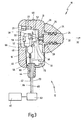
- einen Längsschnitt durch das Gerät in
Figur 1 , wobei Teile des Geräts durch ein Blockschaltbild dargestellt sind.
- FIG. 1
- a medical device for treating the human or animal body by means of pressure or shock waves in a side view;
- FIG. 2
- the device in
FIG. 1 in a front view; and - FIG. 3
- a longitudinal section through the device in
FIG. 1 , wherein parts of the device are represented by a block diagram.
In
Das Gerät 10 weist ein Handstück 12 auf, das eine kompakte Bauweise aufweist, insbesondere im Wesentlichen L-förmig ausgestaltet ist.The
Das Handstück 12 weist ein Gehäuse 14 auf, das in dem gezeigten Ausführungsbeispiel durch ein Gehäusehauptteil 16 und einen Gehäusedeckel 18 gebildet wird, wobei der Gehäusedeckel 18 lösbar mit dem Gehäusehauptteil 16 verbunden ist. Gemäß
Das Gerät 10 weist weiterhin eine Vorrichtung zur Erzeugung von Druck- oder Stoßwellen auf, die nachfolgend näher beschrieben wird.The
Die Vorrichtung zur Erzeugung der Druck- oder Stoßwellen weist zunächst ein Applikatorteil 24 auf, das in dem Gehäuse 14, genauer gesagt in dem Gehäusehauptteil 16, gelagert ist. Zur Fixierung des Applikatorteils 24 an dem Gehäuse 14 ist ein Applikatorhaltekopf 26 vorgesehen, der mit einem Gewindefortsatz 28 des Gehäusehauptteils 16 verschraubt ist. Der Applikatorhaltekopf 26 ist außenseitig konisch ausgebildet.The device for generating the pressure or shock waves initially has an
Von dem Applikatorteil 24 ragt eine distale Austrittsfläche 30 heraus, über die die Druck- oder Stoßwellen in den Körper eines Patienten eingekoppelt werden können.From the
Das Applikatorteil 24 ist in dem Handstück 12 bzw. dem Gehäuse 14 einschließlich des Applikatorhaltekopfs 26 mit einem begrenzten Hub in Richtung eines Pfeils 32 nach distal beweglich, wobei das Applikatorteil 24 in
Der Hub des Applikatorteils 24 ist kleiner als 10 mm, vorzugsweise kleiner als 5 mm.The stroke of the
Die Vorrichtung zur Erzeugung der Druck- oder Stoßwellen weist weiterhin einen pneumatischen Antrieb auf, der nachfolgend näher beschrieben wird.The device for generating the pressure or shock waves further comprises a pneumatic drive, which will be described in more detail below.
Der pneumatische Antrieb verwendet dabei ein unter Druck stehendes Gas, das Stöße in Form von einzelnen Gasdruckstößen auf das Applikatorteil 24 zur Erzeugung der Druck- oder Stoßwellen in dem Applikatorteil 24 ausübt. Die einzelnen Gasdruckstöße wirken dabei unmittelbar auf das Applikatorteil 24, und zwar auf eine proximale Eintrittsfläche 36 des Applikatorteils 24. In unmittelbarer Nähe der proximalen Eintrittsfläche 36 mündet ein Gaszufuhrkanal 38, über den die einzelnen Gasdruckstöße auf die proximale Eintrittsfläche 36 des Applikatorteils 24 gerichtet werden.The pneumatic drive uses a pressurized gas that exerts shocks in the form of individual gas pressure surges on the
Die proximale Eintrittsfläche 36 des Applikatorteils 24 ist großflächig ausgebildet, weist beispielsweise eine Fläche von zumindest 0,5 cm2, vorzugsweise von zumindest 1 cm2 auf. Während der Gaszufuhrkanal 38 gemäß
Damit das über den Gaszufuhrkanal 38 in Form von Gasdruckstößen zugeführte Gas nicht unerwünscht entweicht und somit die gesamte Kraft der Gasdruckstöße auf das Applikatorteil 24 wirken kann, ist das Applikatorteil 24 in dem Gehäuse 14 gasdicht gelagert. Dazu sind nicht näher dargestellte Dichtungen am Applikatorteil 24 bzw. am Gehäuse 14 vorgesehen.So that the gas supplied via the
Das Gas wird in einer Gasdruckquelle 40 bereitgestellt. Die Gasdruckquelle 40 kann ein Kompressor zum Komprimieren von Gas, beispielsweise Luft, oder eine mit einem Gas gefüllte Gasflasche oder ein vergleichbares Druckreservoir sein.The gas is provided in a
Das unter Druck stehende Gas wird über eine Zufuhrleitung 42, beispielsweise einen Druckluftschlauch, dem Handstück 12 zugeführt. Die Zufuhrleitung 42 ist in
Im weiteren Verlauf der Gaszufuhr kann ein Reservoir 48 vorgesehen sein, in dem eine Menge an unter Druck stehendem Gas zwischengespeichert werden kann. Von dem Reservoir 48 führt die Zufuhrleitung 42 weiter zu einem Verteiler 50 für Druckluftzufuhr und für Abluft, wobei der Verteiler 50 mit einem Ventil 52, das insbesondere als Magnetventil ausgebildet ist, verbunden ist.In the further course of the gas supply, a
Das Ventil 52 verbindet je nach seinem Schaltzustand eine Gasleitung 54 wechselweise mit der Zufuhrleitung 42 oder einer Gasabfuhrleitung 56.The
Die Gasleitung 54 mündet in den Gaszufuhrkanal 38.The
Die Gasabfuhrleitung 56 weist einen Schalldämpfer 58 auf, der die bei der Gasströmung entstehenden Geräusche dämpft. Der Schalldämpfer 58 weist eine oder mehrere Kammern auf, die mit einem schalldämpfenden Material gefüllt oder verkleidet sind.The
Im weiteren Verlauf mündet die Gasabfuhrleitung 56 aus dem Gehäuse 14 heraus, beispielsweise an einer Stelle 60.In the course of the
Um das Applikatorteil 24 mit einzelnen Gasdruckstößen zu beaufschlagen, wird das unter Druck stehende Gas über die Zufuhrleitung 42 und den Verteiler 50 bei in Zuführrichtung wiederholt kurzzeitig geöffnetem Ventil 52 stoßartig in den Zufuhrkanal 38 zugeführt, wobei die einzelnen Gasdruckstöße jeweils auf die proximale Eintrittsfläche 36 des Applikatorteils 24 wirken und in dem Applikatorteil 24 Druck- oder Stoßwellen erzeugen, die dann aus der Austrittsfläche 30 austreten und in den Körper eingekoppelt werden. Dazu wird die Austrittsfläche 30 auf die Körperoberfläche aufgesetzt. Die Gasdruckstöße bewirken des Weiteren eine Hubbewegung bzw. Schwingung des Applikatorteils 24.To pressurize the
Die Frequenz, die Amplitude und/oder die Dauer der einzelnen Gasdruckstöße werden durch das Ventil 52 zwangsgesteuert. Nach jedem Gasdruckstoß schließt das Ventil 52 in Zufuhrrichtung und öffnet in Abfuhrrichtung, so dass das Gas nach jedem Gasdruckstoß über die Abfuhrleitung 56 und den Schalldämpfer 58 aus dem Gehäuse 14 entweichen kann.The frequency, the amplitude and / or the duration of the individual gas pressure surges are forcibly controlled by the
Das Gerät weist weiterhin ein Steuergerät 62 auf, mit dem das Handstück 12 verbindbar ist. Das Steuergerät 62 steuert alle wesentlichen Funktionen des Handstücks 12. Das Steuergerät 62 steuert auch die Gaszufuhr aus der Gasdruckquelle 40 in die Zufuhrleitung 42.The device further has a
Über eine erste Steuerleitung bzw. Signalleitung 64 ist das Steuergerät 62 mit einem Steuerkopf 66 des Ventils 52 verbunden, um das Ventil 52 entsprechend zu schalten.Via a first control line or
Eine zweite Steuer- bzw. Signalleitung 65 verbindet das Steuergerät 62 mit einem Auslöser 68. Der Auslöser 68 ist am Handstück 12 an einer ergonomisch günstigen Stelle angeordnet, so dass er beispielsweise mit dem Daumen oder Zeigefinger dersel-ben Hand, die das Handstück 12 hält, betätigt werden kann. Der Auslöser 68 ist als Taster ausgebildet.A second control or
Durch Betätigen des Auslösers 68 werden die Gasdruckstöße ausgelöst, die auf das Applikatorteil 24 wirken. Durch Betätigen des Auslösers 68 schaltet das Steuergerät 62 das Ventil 52 entsprechend der eingestellten Parameter Frequenz, Amplitude und/oder Dauer der zu erzeugenden Gasdruckstöße. Es kann vorgesehen sein, dass bei Betätigen des Auslösers 68 nur ein einzelner Gasdruckstoß erzeugt wird, vorzugsweise wird jedoch bei dauernd betätigtem Auslöser 68 eine kontinuierliche Folge von Gasdruckstößen erzeugt.By actuating the
Über eine weitere Steuer- bzw. Signalleitung 70 ist das Steuergerät 62 mit einer Erkennungsschaltung 72 des Handstücks 12 verbunden, wobei die Erkennungsschaltung 72 es ermöglicht, dass das Steuergerät 62 erkennt, mit welchem Handstück das Steuergerät 62 gerade verbunden ist. Im Rahmen der Erfindung ist es nämlich vorgesehen, eine Mehrzahl verschiedener Handstücke 12 bereitzuhalten, die sich beispielsweise durch das jeweilige Applikatorteil 24 und/oder das Ventil 52 unterscheiden. Durch diese Handstückerkennung kann das Steuergerät 62 bestimmte Parameterbereiche voreinstellen, beispielsweise die Dauer, Frequenz und/oder Amplitude der zu erzeugenden Gasdruckstöße, die zur Erzeugung der Druck- oder Stoßwellen in dem jeweiligen Applikator 24 benötigt werden, um eine bestimmte Wirkung derselben zu erzielen.Via a further control or
In nicht dargestellter Weise können jedoch auch am Handstück 12 oder am Steuergerät 62 Bedienelemente vorgesehen sein, mit denen die vorstehend genannten Parameter der Gasdruckstöße auch während des Betriebs des Geräts 10 verändert bzw. eingestellt werden können.In a manner not shown, however, 62 controls may be provided on the
Das Applikatorteil 24 ist an dem Handstück 12 austauschbar angeordnet, wobei zum Austauschen des Applikatorteils 24 lediglich der Applikatorhaltekopf 26 gelöst bzw. abgenommen werden muss.The
Das Applikatorteil 24 ist insbesondere aus einem Material geringen spezifischen Gewichts, beispielsweise aus einem Leichtmetall, Kunststoff oder auch aus Holz gefertigt. Als Leichtmetalle kann beispielsweise Aluminium oder Titan, als Kunststoff PMMA (Polymethylmetalycrat), PEEK (Polyetheretherketon) oder auch ein weicherer Kunststoff verwendet werden.The
Die Masse des gesamten Handstücks 12 beträgt vorzugsweise weniger als 700 g. Das Verhältnis aus der Masse des Applikatorteils 24 und der Masse des Handstücks ist vorzugsweise kleiner als 1 : 25, vorzugsweise kleiner als 1 : 50.The mass of the
Im Falle, dass das Applikatorteil 24 austauschbar ist, werden vorzugsweise eine Mehrzahl von Applikatorteilen 24 vorgesehen, die sich hinsichtlich Größe, Masse, Material, Form der distalen Austrittsfläche 30 und/oder Größe der distalen Austrittsfläche 30 unterscheiden. Auf diese Weise kann das für die vorzunehmende Behandlung des Patienten günstigste Applikatorteil 24 verwendet werden.In the case that the
Außerdem kann vorgesehen sein, dass die Austrittsfläche 30 des Applikatorteils 24 eine Form aufweist, die in unterschiedlichen Richtungen quer zur Längsrichtung (entspricht dem Pfeil 32 in
Während das in der Zeichnung dargestellte Ausführungsbeispiel des medizinischen Geräts 10 insbesondere für die Schmerztherapie im knochennahen Weichteilbereich geeignet ist, kann das Applikatorteil 24 für andere Verwendungszwecke des Gerätes 10, beispielsweise zur Zertrümmerung von Körpersteinen im Körper, als dünne lange Sonde ausgebildet sein, so dass das Applikatorteil 24 beispielsweise über den Harnweg in den Körper eingeführt werden kann.While the illustrated in the drawing embodiment of the
Durch eine entsprechende Anpassung des Applikatorteils 24 können weitere Einsatzgebiete in Betracht gezogen werden, beispielsweise die Verwendung zum Eintreiben von Nägeln im Knochen, Abtragen von Knochenzement, usw.By appropriate adaptation of the
Während das Applikatorteil 24 in dem gezeigten Ausführungsbeispiel einteilig dargestellt ist, versteht es sich, dass das Applikatorteil 24 auch mehrteilig ausgebildet sein kann, beispielsweise auch aus mehreren unterschiedlichen Materialien aufgebaut sein kann.While the
Claims (15)
- A medical apparatus for treatment of the human or animal body by pressure waves or shock waves, comprising a device designed to generate the pressure waves or shock waves and having at least one applicator part (24), a housing (14) and a pneumatic drive which, by means of a pressurized gas, repeatedly generates impacts on a proximal input face (36) of the applicator part (24) in order, with the applicator part (24), to generate pressure waves or shock waves that are applied from the applicator part (24) into the body by way of a distal output face (30), wherein the applicator part (24) is mounted in the housing in movable fashion from a proximal starting position in distal direction an with a limited stroke, characterized in that the pressurized gas acts, in the form of individual gas pressure pulses, directly on the applicator part (24) to generate the pressure waves or shock waves.
- The apparatus of Claim 1, characterized in that the applicator part (24) is mounted in a gas-tight manner in the housing (14).
- The apparatus of Claim 1 or 2, characterized in that the applicator part (24) is pretensioned elastically in a proximal starting position.
- The apparatus of any one of Claims 1 through 3, characterized in that the applicator part (24) is made from a material of low specific weight, for example a light metal, plastic or wood.
- The apparatus of any one of Claims 1 through 4, characterized in that the gas pressure pulses are controlled by at least one valve (52).
- The apparatus of Claim 5, characterized in that the at least one valve (52) is a solenoid valve.
- The apparatus of any one of Claims 1 through 6, characterized in that the apparatus (10) has a handpiece (12) that comprises the at least one applicator part (24).
- The apparatus of Claim 7, characterized in that the ratio of mass of the hand-piece (12) to mass of the applicator part (24) is greater than 25:1, preferably greater than 50:1.
- The apparatus of Claim 7 or 8, characterized in that a trigger (68) for triggering the gas pressure pulses in single operation or continuous operation is arranged on the handpiece (12).
- The apparatus of any one of Claims 7 through 9, characterized in that the handpiece (12) can be connected to a control device (62), in which case a plurality of handpieces (12) are provided, and the control device (62) detects the handpiece to which the control device (62) is connected.
- The apparatus of Claim 5 or 6 and of any one of Claims 7 through 10, characterized in that the at least one valve (52) is arranged in the handpiece (12).
- The apparatus of any one of Claims 1 through 11, characterized in that the frequency, the amplitude and/or the duration of the gas pressure pulses is/are adjustable.
- The apparatus of any one of Claims 7 through 10 and of Claim 12, characterized in that the frequency, the amplitude and/or the pressure can be adjusted on the handpiece (12).
- The apparatus of any one of Claims 1 through 13, characterized in that the output face (30) of the applicator part (24) has a shape that has different dimensions in different directions transverse to the longitudinal direction.
- The apparatus of any one of Claims 1 through 14, characterized in that the frequency of the gas pressure pulses is greater than 20 Hz, preferably greater than 30 Hz.
Applications Claiming Priority (2)
| Application Number | Priority Date | Filing Date | Title |
|---|---|---|---|
| DE202007007921U DE202007007921U1 (en) | 2007-05-31 | 2007-05-31 | Medical device for treating the human or animal body with pressure or shock waves |
| PCT/EP2008/003986 WO2008145269A1 (en) | 2007-05-31 | 2008-05-17 | Medical device for the treatment of the human or animal body using pressure or impact waves |
Publications (2)
| Publication Number | Publication Date |
|---|---|
| EP2157921A1 EP2157921A1 (en) | 2010-03-03 |
| EP2157921B1 true EP2157921B1 (en) | 2014-04-02 |
Family
ID=39720218
Family Applications (1)
| Application Number | Title | Priority Date | Filing Date |
|---|---|---|---|
| EP08758605.3A Active EP2157921B1 (en) | 2007-05-31 | 2008-05-17 | Medical device for the treatment of the human or animal body using pressure or impact waves |
Country Status (4)
| Country | Link |
|---|---|
| US (1) | US20100137760A1 (en) |
| EP (1) | EP2157921B1 (en) |
| DE (1) | DE202007007921U1 (en) |
| WO (1) | WO2008145269A1 (en) |
Cited By (2)
| Publication number | Priority date | Publication date | Assignee | Title |
|---|---|---|---|---|
| DE202021100954U1 (en) | 2021-02-25 | 2022-05-30 | Storz Medical Ag | Device for treating the human or animal body with mechanical shocks |
| DE102021104566A1 (en) | 2021-02-25 | 2022-08-25 | Storz Medical Ag | Device for treating the human or animal body with mechanical impact |
Families Citing this family (17)
| Publication number | Priority date | Publication date | Assignee | Title |
|---|---|---|---|---|
| EP2181730B1 (en) | 2008-10-31 | 2012-08-29 | Ferton Holding SA | Instrument for producing shock wave-like pressure waves for treating biological tissue |
| DE202009001238U1 (en) | 2009-02-02 | 2010-06-24 | Storz Medical Ag | Pressure wave treatment device with parameter setting |
| DE202009004616U1 (en) * | 2009-04-03 | 2010-08-19 | Storz Medical Ag | Device for treating the human or animal body by means of mechanical pressure waves with an exchangeable impact body |
| DE102009049924A1 (en) | 2009-10-19 | 2011-05-12 | Storz Medical Ag | Pressure wave device with pneumatic drive |
| EP2351530B1 (en) * | 2010-01-28 | 2013-01-23 | Storz Medical Ag | Handheld shockwave apparatus having a pressing device |
| DE102011015584A1 (en) * | 2011-03-30 | 2012-10-04 | Geuder Ag | Surgical hand tool |
| EP2529678B1 (en) | 2011-05-31 | 2015-01-28 | Storz Medical Ag | Pressure wave device for treating the human or animal body |
| DE102011088972A1 (en) * | 2011-12-19 | 2013-06-20 | Robert Bosch Gmbh | Pneumatic tool device |
| US9931151B2 (en) * | 2014-01-16 | 2018-04-03 | Archer Sciences, LLC | Impactor and remover devices |
| US11484724B2 (en) | 2015-09-30 | 2022-11-01 | Btl Medical Solutions A.S. | Methods and devices for tissue treatment using mechanical stimulation and electromagnetic field |
| DE102016003854A1 (en) | 2016-03-26 | 2017-09-28 | Gerd Straßmann | Optimization of the sound pressure wave therapy of a tumor |
| US11083512B2 (en) | 2016-08-31 | 2021-08-10 | DePuy Synthes Products, Inc. | Orthopedic device delivering a controlled, repeatable impact |
| EP4147655A1 (en) | 2016-08-31 | 2023-03-15 | DePuy Synthes Products, Inc. | Orthopedic impacting device having a launched mass delivering a controlled, repeatable & reversible impacting force |
| KR102371305B1 (en) * | 2016-08-31 | 2022-03-08 | 메디컬 엔터프라이시스 디스트리부션 엘엘씨 | Orthopedic Devices Delivering Controlled, Repeatable Impacts |
| CN107811834A (en) * | 2017-11-30 | 2018-03-20 | 广东美的安川服务机器人有限公司 | Shock wave treatment instrument and its control method |
| CN107929019A (en) * | 2017-11-30 | 2018-04-20 | 广东美的安川服务机器人有限公司 | Shock wave treatment instrument and its control method |
| CN108042334A (en) * | 2017-12-18 | 2018-05-18 | 广东美的安川服务机器人有限公司 | Fluid pressure type shock wave treatment instrument |
Family Cites Families (22)
| Publication number | Priority date | Publication date | Assignee | Title |
|---|---|---|---|---|
| US3289672A (en) * | 1964-02-27 | 1966-12-06 | Westinghouse Electric Corp | Heart resuscitator apparatus |
| US3234934A (en) * | 1965-04-06 | 1966-02-15 | Kenneth E Woodward | Fluid amplifier controlled piston |
| US3955563A (en) * | 1975-01-06 | 1976-05-11 | Albert Maione | Pneumatic percussor |
| US4016873A (en) * | 1976-04-01 | 1977-04-12 | Anderson Otis F | Pneumatic impacter |
| US4398531A (en) * | 1979-06-21 | 1983-08-16 | Hudson Oxygen Therapy Sales Company | Percussor |
| US4390013A (en) * | 1980-12-29 | 1983-06-28 | Hudson Oxygen Therapy Sales Company | Percussor assembly |
| US4512339A (en) * | 1981-04-24 | 1985-04-23 | Mcshirley Products, Inc. | Percussor application |
| US4387708A (en) * | 1981-05-18 | 1983-06-14 | Davis James E P | Pneumatic percussor |
| US4716890A (en) * | 1986-01-29 | 1988-01-05 | Bichel Ronald A | Chiropractic thruster |
| US4691693A (en) * | 1986-09-02 | 1987-09-08 | Magnetic Massage Company | Massage device |
| US5425735A (en) | 1989-02-22 | 1995-06-20 | Psi Medical Products, Inc. | Shielded tip catheter for lithotripsy |
| DE19524380C2 (en) | 1995-07-04 | 1997-10-09 | Steinweg Friedhelm Dr Med | Massage device, in particular for use in decongestive therapy |
| DE19624446C1 (en) * | 1996-06-19 | 1998-03-26 | Ferton Holding | Surgical instrument for mechanical removal of bone cement, and method for generating shock waves |
| KR100294266B1 (en) * | 1996-10-29 | 2001-07-12 | 윤종용 | Computer and peripheral with auto-negotiation by analog signal level |
| TR199901709T2 (en) * | 1997-01-23 | 1999-09-21 | Ulrich G. Randoll Dr. | Massage tool. |
| DE19725477C2 (en) | 1997-06-17 | 1999-10-21 | Ferton Holding | Medical instrument for the treatment of biological tissue |
| US6503211B2 (en) * | 2001-05-25 | 2003-01-07 | Bruce A. Frye | Pneumatic spinal and extremity manipulator |
| US6695837B2 (en) * | 2002-03-13 | 2004-02-24 | Starion Instruments Corporation | Power supply for identification and control of electrical surgical tools |
| DE10215416B4 (en) * | 2002-04-08 | 2020-10-29 | Ferton Holding S.A. | Medical device for the treatment of biological tissue |
| US6875186B2 (en) * | 2002-09-05 | 2005-04-05 | Kevin B. Tucek | Pressure-actuated percussive device |
| FR2851153B1 (en) * | 2003-02-14 | 2005-04-08 | Alain Lebet | GENERATING DEVICE OF A SHOCK WAVE WAVE. |
| DE102005022034A1 (en) * | 2004-05-13 | 2006-01-12 | Uwe Thee | Medical instrument for treating biological tissue for assisting the healing process with an element for converting input induced pressure waves to damped form at the output |
-
2007
- 2007-05-31 DE DE202007007921U patent/DE202007007921U1/en not_active Expired - Lifetime
-
2008
- 2008-05-17 EP EP08758605.3A patent/EP2157921B1/en active Active
- 2008-05-17 WO PCT/EP2008/003986 patent/WO2008145269A1/en active Application Filing
-
2009
- 2009-11-30 US US12/627,778 patent/US20100137760A1/en not_active Abandoned
Cited By (2)
| Publication number | Priority date | Publication date | Assignee | Title |
|---|---|---|---|---|
| DE202021100954U1 (en) | 2021-02-25 | 2022-05-30 | Storz Medical Ag | Device for treating the human or animal body with mechanical shocks |
| DE102021104566A1 (en) | 2021-02-25 | 2022-08-25 | Storz Medical Ag | Device for treating the human or animal body with mechanical impact |
Also Published As
| Publication number | Publication date |
|---|---|
| US20100137760A1 (en) | 2010-06-03 |
| DE202007007921U1 (en) | 2008-10-09 |
| EP2157921A1 (en) | 2010-03-03 |
| WO2008145269A1 (en) | 2008-12-04 |
Similar Documents
| Publication | Publication Date | Title |
|---|---|---|
| EP2157921B1 (en) | Medical device for the treatment of the human or animal body using pressure or impact waves | |
| EP3960237B1 (en) | Instrument for treating biological tissue with shock wave like pressure waves | |
| EP2344252B1 (en) | Device for introducing shock waves into a living body and use thereof | |
| DE102006062356B3 (en) | Appliance to apply pressure shock waves, at the body of human and animal patients, has a reciprocating hammer powered by a controlled pneumatic drive to strike a beating body repeatedly | |
| EP2213273B2 (en) | Setting parameters for a device for shock wave treatment | |
| DE19725477C2 (en) | Medical instrument for the treatment of biological tissue | |
| DE19961027B4 (en) | Medical instrument for treating tissue or bone cement in the human or animal body | |
| DE202004011323U1 (en) | Instrument for applying vibrations to the human body | |
| DE202010001176U1 (en) | Medical pressure wave device | |
| DE10215416B4 (en) | Medical device for the treatment of biological tissue | |
| DE102006057268A1 (en) | Medical device for treating the human or animal body with mechanical pressure or shock waves | |
| DE102009042276A1 (en) | Device for introducing shock wave into living body i.e. human body, in hand-held medical device for e.g. intracorporeal shock wave lithotripsy, has tensioning device allowing abrupt release of spring while delivering shock pulses | |
| DE102005022034A1 (en) | Medical instrument for treating biological tissue for assisting the healing process with an element for converting input induced pressure waves to damped form at the output | |
| WO2008145273A1 (en) | Medical device for the treatment of the human or animal body using mechanical pressure or impact waves | |
| EP2289435A1 (en) | Pressure wave device for treating the human or animal body with piezo layer stack | |
| DE102008051174A1 (en) | Device for introducing shock wave into living body i.e. human body, in hand-held medical device for e.g. intracorporeal shock wave lithotripsy, has tensioning device allowing abrupt release of spring while delivering shock pulses | |
| DE102022126984A1 (en) | Lithotripsy device for breaking up body stones with a counter-projectile and method for accelerating a projectile of a lithotripsy device |
Legal Events
| Date | Code | Title | Description |
|---|---|---|---|
| PUAI | Public reference made under article 153(3) epc to a published international application that has entered the european phase |
Free format text: ORIGINAL CODE: 0009012 |
|
| 17P | Request for examination filed |
Effective date: 20091216 |
|
| AK | Designated contracting states |
Kind code of ref document: A1 Designated state(s): AT BE BG CH CY CZ DE DK EE ES FI FR GB GR HR HU IE IS IT LI LT LU LV MC MT NL NO PL PT RO SE SI SK TR |
|
| AX | Request for extension of the european patent |
Extension state: AL BA MK RS |
|
| DAX | Request for extension of the european patent (deleted) | ||
| 17Q | First examination report despatched |
Effective date: 20120131 |
|
| REG | Reference to a national code |
Ref country code: DE Ref legal event code: R079 Ref document number: 502008011541 Country of ref document: DE Free format text: PREVIOUS MAIN CLASS: A61B0017220000 Ipc: A61B0017160000 |
|
| RIC1 | Information provided on ipc code assigned before grant |
Ipc: A61B 17/00 20060101ALI20130716BHEP Ipc: A61H 23/02 20060101ALI20130716BHEP Ipc: A61B 17/16 20060101AFI20130716BHEP Ipc: A61B 17/88 20060101ALI20130716BHEP Ipc: A61H 23/00 20060101ALI20130716BHEP Ipc: A61B 17/22 20060101ALI20130716BHEP Ipc: A61B 17/92 20060101ALI20130716BHEP |
|
| GRAP | Despatch of communication of intention to grant a patent |
Free format text: ORIGINAL CODE: EPIDOSNIGR1 |
|
| INTG | Intention to grant announced |
Effective date: 20131009 |
|
| GRAS | Grant fee paid |
Free format text: ORIGINAL CODE: EPIDOSNIGR3 |
|
| GRAA | (expected) grant |
Free format text: ORIGINAL CODE: 0009210 |
|
| RIN1 | Information on inventor provided before grant (corrected) |
Inventor name: KATONA, JOSEF Inventor name: SCHULZ, MANFRED Inventor name: MARLINGHAUS, ERNST, H. Inventor name: NOVAK, PAVEL Inventor name: MUELHAUSER, PETER, CHRISTIAN |
|
| AK | Designated contracting states |
Kind code of ref document: B1 Designated state(s): AT BE BG CH CY CZ DE DK EE ES FI FR GB GR HR HU IE IS IT LI LT LU LV MC MT NL NO PL PT RO SE SI SK TR |
|
| REG | Reference to a national code |
Ref country code: GB Ref legal event code: FG4D Free format text: NOT ENGLISH |
|
| REG | Reference to a national code |
Ref country code: CH Ref legal event code: EP Ref country code: CH Ref legal event code: NV Representative=s name: TROESCH SCHEIDEGGER WERNER AG, CH Ref country code: AT Ref legal event code: REF Ref document number: 659592 Country of ref document: AT Kind code of ref document: T Effective date: 20140415 |
|
| REG | Reference to a national code |
Ref country code: IE Ref legal event code: FG4D Free format text: LANGUAGE OF EP DOCUMENT: GERMAN |
|
| REG | Reference to a national code |
Ref country code: DE Ref legal event code: R096 Ref document number: 502008011541 Country of ref document: DE Effective date: 20140508 |
|
| REG | Reference to a national code |
Ref country code: NL Ref legal event code: VDEP Effective date: 20140402 |
|
| REG | Reference to a national code |
Ref country code: LT Ref legal event code: MG4D |
|
| PG25 | Lapsed in a contracting state [announced via postgrant information from national office to epo] |
Ref country code: GR Free format text: LAPSE BECAUSE OF FAILURE TO SUBMIT A TRANSLATION OF THE DESCRIPTION OR TO PAY THE FEE WITHIN THE PRESCRIBED TIME-LIMIT Effective date: 20140703 Ref country code: FI Free format text: LAPSE BECAUSE OF FAILURE TO SUBMIT A TRANSLATION OF THE DESCRIPTION OR TO PAY THE FEE WITHIN THE PRESCRIBED TIME-LIMIT Effective date: 20140402 Ref country code: CZ Free format text: LAPSE BECAUSE OF FAILURE TO SUBMIT A TRANSLATION OF THE DESCRIPTION OR TO PAY THE FEE WITHIN THE PRESCRIBED TIME-LIMIT Effective date: 20140402 Ref country code: LT Free format text: LAPSE BECAUSE OF FAILURE TO SUBMIT A TRANSLATION OF THE DESCRIPTION OR TO PAY THE FEE WITHIN THE PRESCRIBED TIME-LIMIT Effective date: 20140402 Ref country code: IS Free format text: LAPSE BECAUSE OF FAILURE TO SUBMIT A TRANSLATION OF THE DESCRIPTION OR TO PAY THE FEE WITHIN THE PRESCRIBED TIME-LIMIT Effective date: 20140802 Ref country code: NO Free format text: LAPSE BECAUSE OF FAILURE TO SUBMIT A TRANSLATION OF THE DESCRIPTION OR TO PAY THE FEE WITHIN THE PRESCRIBED TIME-LIMIT Effective date: 20140702 Ref country code: NL Free format text: LAPSE BECAUSE OF FAILURE TO SUBMIT A TRANSLATION OF THE DESCRIPTION OR TO PAY THE FEE WITHIN THE PRESCRIBED TIME-LIMIT Effective date: 20140402 Ref country code: BG Free format text: LAPSE BECAUSE OF FAILURE TO SUBMIT A TRANSLATION OF THE DESCRIPTION OR TO PAY THE FEE WITHIN THE PRESCRIBED TIME-LIMIT Effective date: 20140702 Ref country code: CY Free format text: LAPSE BECAUSE OF FAILURE TO SUBMIT A TRANSLATION OF THE DESCRIPTION OR TO PAY THE FEE WITHIN THE PRESCRIBED TIME-LIMIT Effective date: 20140402 |
|
| PG25 | Lapsed in a contracting state [announced via postgrant information from national office to epo] |
Ref country code: ES Free format text: LAPSE BECAUSE OF FAILURE TO SUBMIT A TRANSLATION OF THE DESCRIPTION OR TO PAY THE FEE WITHIN THE PRESCRIBED TIME-LIMIT Effective date: 20140402 Ref country code: SE Free format text: LAPSE BECAUSE OF FAILURE TO SUBMIT A TRANSLATION OF THE DESCRIPTION OR TO PAY THE FEE WITHIN THE PRESCRIBED TIME-LIMIT Effective date: 20140402 Ref country code: LV Free format text: LAPSE BECAUSE OF FAILURE TO SUBMIT A TRANSLATION OF THE DESCRIPTION OR TO PAY THE FEE WITHIN THE PRESCRIBED TIME-LIMIT Effective date: 20140402 Ref country code: HR Free format text: LAPSE BECAUSE OF FAILURE TO SUBMIT A TRANSLATION OF THE DESCRIPTION OR TO PAY THE FEE WITHIN THE PRESCRIBED TIME-LIMIT Effective date: 20140402 Ref country code: PL Free format text: LAPSE BECAUSE OF FAILURE TO SUBMIT A TRANSLATION OF THE DESCRIPTION OR TO PAY THE FEE WITHIN THE PRESCRIBED TIME-LIMIT Effective date: 20140402 |
|
| PG25 | Lapsed in a contracting state [announced via postgrant information from national office to epo] |
Ref country code: PT Free format text: LAPSE BECAUSE OF FAILURE TO SUBMIT A TRANSLATION OF THE DESCRIPTION OR TO PAY THE FEE WITHIN THE PRESCRIBED TIME-LIMIT Effective date: 20140804 |
|
| REG | Reference to a national code |
Ref country code: DE Ref legal event code: R097 Ref document number: 502008011541 Country of ref document: DE |
|
| PG25 | Lapsed in a contracting state [announced via postgrant information from national office to epo] |
Ref country code: EE Free format text: LAPSE BECAUSE OF FAILURE TO SUBMIT A TRANSLATION OF THE DESCRIPTION OR TO PAY THE FEE WITHIN THE PRESCRIBED TIME-LIMIT Effective date: 20140402 Ref country code: DK Free format text: LAPSE BECAUSE OF FAILURE TO SUBMIT A TRANSLATION OF THE DESCRIPTION OR TO PAY THE FEE WITHIN THE PRESCRIBED TIME-LIMIT Effective date: 20140402 Ref country code: SK Free format text: LAPSE BECAUSE OF FAILURE TO SUBMIT A TRANSLATION OF THE DESCRIPTION OR TO PAY THE FEE WITHIN THE PRESCRIBED TIME-LIMIT Effective date: 20140402 Ref country code: RO Free format text: LAPSE BECAUSE OF FAILURE TO SUBMIT A TRANSLATION OF THE DESCRIPTION OR TO PAY THE FEE WITHIN THE PRESCRIBED TIME-LIMIT Effective date: 20140402 Ref country code: MC Free format text: LAPSE BECAUSE OF FAILURE TO SUBMIT A TRANSLATION OF THE DESCRIPTION OR TO PAY THE FEE WITHIN THE PRESCRIBED TIME-LIMIT Effective date: 20140402 |
|
| PLBE | No opposition filed within time limit |
Free format text: ORIGINAL CODE: 0009261 |
|
| STAA | Information on the status of an ep patent application or granted ep patent |
Free format text: STATUS: NO OPPOSITION FILED WITHIN TIME LIMIT |
|
| REG | Reference to a national code |
Ref country code: IE Ref legal event code: MM4A |
|
| 26N | No opposition filed |
Effective date: 20150106 |
|
| REG | Reference to a national code |
Ref country code: DE Ref legal event code: R097 Ref document number: 502008011541 Country of ref document: DE Effective date: 20150106 |
|
| PG25 | Lapsed in a contracting state [announced via postgrant information from national office to epo] |
Ref country code: IE Free format text: LAPSE BECAUSE OF NON-PAYMENT OF DUE FEES Effective date: 20140517 |
|
| REG | Reference to a national code |
Ref country code: AT Ref legal event code: MM01 Ref document number: 659592 Country of ref document: AT Kind code of ref document: T Effective date: 20140517 |
|
| PG25 | Lapsed in a contracting state [announced via postgrant information from national office to epo] |
Ref country code: SI Free format text: LAPSE BECAUSE OF FAILURE TO SUBMIT A TRANSLATION OF THE DESCRIPTION OR TO PAY THE FEE WITHIN THE PRESCRIBED TIME-LIMIT Effective date: 20140402 |
|
| PG25 | Lapsed in a contracting state [announced via postgrant information from national office to epo] |
Ref country code: AT Free format text: LAPSE BECAUSE OF NON-PAYMENT OF DUE FEES Effective date: 20140517 |
|
| PG25 | Lapsed in a contracting state [announced via postgrant information from national office to epo] |
Ref country code: MT Free format text: LAPSE BECAUSE OF FAILURE TO SUBMIT A TRANSLATION OF THE DESCRIPTION OR TO PAY THE FEE WITHIN THE PRESCRIBED TIME-LIMIT Effective date: 20140402 |
|
| REG | Reference to a national code |
Ref country code: FR Ref legal event code: PLFP Year of fee payment: 9 |
|
| PG25 | Lapsed in a contracting state [announced via postgrant information from national office to epo] |
Ref country code: HU Free format text: LAPSE BECAUSE OF FAILURE TO SUBMIT A TRANSLATION OF THE DESCRIPTION OR TO PAY THE FEE WITHIN THE PRESCRIBED TIME-LIMIT; INVALID AB INITIO Effective date: 20080517 Ref country code: BE Free format text: LAPSE BECAUSE OF FAILURE TO SUBMIT A TRANSLATION OF THE DESCRIPTION OR TO PAY THE FEE WITHIN THE PRESCRIBED TIME-LIMIT Effective date: 20140531 Ref country code: LU Free format text: LAPSE BECAUSE OF NON-PAYMENT OF DUE FEES Effective date: 20140517 Ref country code: TR Free format text: LAPSE BECAUSE OF FAILURE TO SUBMIT A TRANSLATION OF THE DESCRIPTION OR TO PAY THE FEE WITHIN THE PRESCRIBED TIME-LIMIT Effective date: 20140402 |
|
| REG | Reference to a national code |
Ref country code: FR Ref legal event code: PLFP Year of fee payment: 10 |
|
| REG | Reference to a national code |
Ref country code: FR Ref legal event code: PLFP Year of fee payment: 11 |
|
| PGFP | Annual fee paid to national office [announced via postgrant information from national office to epo] |
Ref country code: GB Payment date: 20200527 Year of fee payment: 13 |
|
| GBPC | Gb: european patent ceased through non-payment of renewal fee |
Effective date: 20210517 |
|
| PG25 | Lapsed in a contracting state [announced via postgrant information from national office to epo] |
Ref country code: GB Free format text: LAPSE BECAUSE OF NON-PAYMENT OF DUE FEES Effective date: 20210517 |
|
| PGFP | Annual fee paid to national office [announced via postgrant information from national office to epo] |
Ref country code: IT Payment date: 20230526 Year of fee payment: 16 Ref country code: FR Payment date: 20230525 Year of fee payment: 16 Ref country code: DE Payment date: 20230620 Year of fee payment: 16 Ref country code: CH Payment date: 20230605 Year of fee payment: 16 |