EP2157359A2 - Artificial light source generator - Google Patents
Artificial light source generator Download PDFInfo
- Publication number
- EP2157359A2 EP2157359A2 EP09166944A EP09166944A EP2157359A2 EP 2157359 A2 EP2157359 A2 EP 2157359A2 EP 09166944 A EP09166944 A EP 09166944A EP 09166944 A EP09166944 A EP 09166944A EP 2157359 A2 EP2157359 A2 EP 2157359A2
- Authority
- EP
- European Patent Office
- Prior art keywords
- lens array
- light source
- lens
- light beams
- lens units
- Prior art date
- Legal status (The legal status is an assumption and is not a legal conclusion. Google has not performed a legal analysis and makes no representation as to the accuracy of the status listed.)
- Granted
Links
- 229910052724 xenon Inorganic materials 0.000 claims description 6
- FHNFHKCVQCLJFQ-UHFFFAOYSA-N xenon atom Chemical compound [Xe] FHNFHKCVQCLJFQ-UHFFFAOYSA-N 0.000 claims description 6
- 239000011248 coating agent Substances 0.000 claims description 4
- 238000000576 coating method Methods 0.000 claims description 4
- 239000000463 material Substances 0.000 claims description 4
- 238000005286 illumination Methods 0.000 abstract description 13
- 238000012360 testing method Methods 0.000 description 9
- 239000011247 coating layer Substances 0.000 description 3
- 238000000034 method Methods 0.000 description 3
- 238000001228 spectrum Methods 0.000 description 3
- 239000002131 composite material Substances 0.000 description 2
- 238000012986 modification Methods 0.000 description 2
- 230000004048 modification Effects 0.000 description 2
- 238000003491 array Methods 0.000 description 1
- 230000002238 attenuated effect Effects 0.000 description 1
- 238000013461 design Methods 0.000 description 1
- 238000011161 development Methods 0.000 description 1
- 238000004134 energy conservation Methods 0.000 description 1
- 230000007613 environmental effect Effects 0.000 description 1
- 238000004519 manufacturing process Methods 0.000 description 1
- 239000002905 metal composite material Substances 0.000 description 1
- 238000002791 soaking Methods 0.000 description 1
- WFKWXMTUELFFGS-UHFFFAOYSA-N tungsten Chemical compound [W] WFKWXMTUELFFGS-UHFFFAOYSA-N 0.000 description 1
- 229910052721 tungsten Inorganic materials 0.000 description 1
- 239000010937 tungsten Substances 0.000 description 1
Images


Classifications
-
- F—MECHANICAL ENGINEERING; LIGHTING; HEATING; WEAPONS; BLASTING
- F21—LIGHTING
- F21V—FUNCTIONAL FEATURES OR DETAILS OF LIGHTING DEVICES OR SYSTEMS THEREOF; STRUCTURAL COMBINATIONS OF LIGHTING DEVICES WITH OTHER ARTICLES, NOT OTHERWISE PROVIDED FOR
- F21V9/00—Elements for modifying spectral properties, polarisation or intensity of the light emitted, e.g. filters
- F21V9/02—Elements for modifying spectral properties, polarisation or intensity of the light emitted, e.g. filters for simulating daylight
-
- F—MECHANICAL ENGINEERING; LIGHTING; HEATING; WEAPONS; BLASTING
- F21—LIGHTING
- F21S—NON-PORTABLE LIGHTING DEVICES; SYSTEMS THEREOF; VEHICLE LIGHTING DEVICES SPECIALLY ADAPTED FOR VEHICLE EXTERIORS
- F21S8/00—Lighting devices intended for fixed installation
- F21S8/006—Solar simulators, e.g. for testing photovoltaic panels
-
- F—MECHANICAL ENGINEERING; LIGHTING; HEATING; WEAPONS; BLASTING
- F21—LIGHTING
- F21V—FUNCTIONAL FEATURES OR DETAILS OF LIGHTING DEVICES OR SYSTEMS THEREOF; STRUCTURAL COMBINATIONS OF LIGHTING DEVICES WITH OTHER ARTICLES, NOT OTHERWISE PROVIDED FOR
- F21V5/00—Refractors for light sources
- F21V5/008—Combination of two or more successive refractors along an optical axis
Abstract
Description
- The present invention relates to an artificial light source generator, and more particularly to an artificial light source generator capable of simulating natural light in a large area.
- As public awareness about environmental protection and energy conservation is on the rise, many efforts are being made to developed solar cell modules. However, one of the major challenges for development of solar cell module is testing after manufacturing. The intensity of natural light (sunlight) changes at different points of a day and is difficult to control artificially, so solar cell modules are generally not placed outdoors for testing. In conventional testing, an artificial light source is used indoors to simulate sunlight, so as to obtain relevant product characteristics of the solar cell modules.
- Two conventional testing methods are described below. In the first method, a flash xenon lamp is used with a flash time of about tens of milliseconds each time, which covers a flash area of more than 1 * 1 square meter, and can meet the uniformity requirements by means of the profile design of lighting fixtures and lamps. The disadvantage of this method is that the flash time is too short, so it is difficult to obtain correct or sufficient voltage and current data. Further, light soaking or hot spot tests that require light irradiation for a long time cannot be performed in this testing method.
-
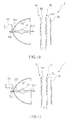
FIG. 1 shows a schematic view of a projection plane in the second conventional testing method. A plurality of sets of continuum lamps (for example, 6 sets) is used for irradiation, so as to form six illumination regions 11 on aprojection plane 10. The lamps may be tungsten lamps, metal-composite lamps, xenon lamps, or other light sources capable of emitting lights stably and achieving a required spectrum after being filtered by a filter mirror. The lamps are arranged adjacent to one another in a specific manner so that the illumination uniformity of theprojection plane 10 meets certain requirements. If necessary, a shading material (for example, wire net) is applied between the lamps and theprojection plane 10, so as to reduce the light on a certain region to meet the illumination uniformity required for thewhole projection plane 10. - The disadvantage of this method is that the position and intensity of each lamp and the density of the wire net must be adjusted to achieve the required uniformity, which is rather difficult and labor-consuming. Generally, it takes about ten days to make one adjustment. Whenever the attenuation of a certain lamp differs from that of the other lamps, the adjustment must be made again. For example, if the lamp on the top left corner of the illumination region 11 is attenuated too fast, the illumination region 11 will be darker than the other illumination regions, and a readjustment will be needed. In addition, if the overall uniformity deteriorates due to the shift of a certain component, a readjustment will also be needed.
- Therefore, it is necessary to provide an artificial light source generator to solve the above problems.
- The present invention is directed to an artificial light source generator, which includes at least one luminescent set and a projection plane. The luminescent set includes a light source, a parabolic mirror, a supporting seat, a first lens array, and a second lens array. The light source is used to generate light beams. The parabolic mirror has a focus, and the light source is disposed at the focus, so that the light beams generated by the light source are reflected or emitted in a parallel direction by the parabolic mirror. The supporting seat is used for supporting the light source. The first lens array has a plurality of first lens units, and each of the first lens units has a first focal distance. The second lens array has a plurality of second lens units, and the second lens array is parallel to the first lens array. The distance between the second lens array and the first lens array is 0.5 to 1.5 times the first focal distance. The projection plane is used for placing a module being tested. The projection plane is separated from the luminescent set at a suitable distance, so that the light beams passing through the first lens array and the second lens array are projected on the projection plane. The light beams passing through each of the second lens units cover the entire projection plane.
- The present invention has the following advantages. A nonuniformity performance of under 5% is achieved when a single luminescent set is used to project light beams on the projection plane, and more preferred overall illumination uniformity can be achieved when a plurality of luminescent sets is used to project light beams on the projection plane. Furthermore, the uniformity will not deteriorate due to an output attenuation of a certain luminescent set. In addition, when a plurality of luminescent sets is employed for irradiation in an overlapping manner, each luminescent set can adopt a different light source or filter mirror to produce light beams at different wavelengths, so as to generate a composite spectrum on the projection plane. If different luminance is required, a part of the luminescent sets can be shaded or turned off without affecting the illumination uniformity on the projection plane.
-
-
FIG. 1 is a schematic view of a projection plane in a second conventional testing method; -
FIG. 2 is a schematic view of an artificial light source generator according to a first embodiment of the present invention; -
FIG. 3 is a schematic view of a luminescent set in the artificial light source generator according to the first embodiment of the present invention; -
FIG. 4 is a schematic view of light paths of a second lens array in the artificial light source generator according to the present invention; -
FIG. 5 is a schematic view of another implementation aspect of the artificial light source generator according to the first embodiment of the present invention, in which an angle is formed between the filter mirror and the second lens array; -
FIG. 6 shows a profile of the first lens units and the second lens units according to the first embodiment of the present invention, in which the profile is rectangular; -
FIG. 7 shows a profile of the first lens units and the second lens units according to the first embodiment of the present invention, in which the profile is hexagonal; -
FIG. 8 shows a profile of the first lens units and the second lens units according to the first embodiment of the present invention, in which the first lens units and the second lens units are divided into four regions where lenses are gathered; -
FIG. 9 is a schematic view of an artificial light source generator according to a second embodiment of the present invention; -
FIG. 10 is a schematic view of a first luminescent set in the artificial light source generator according to the second embodiment of the present invention; and -
FIG. 11 is a schematic view of a second luminescent set in the artificial light source generator according to the second embodiment of the present invention. -
FIGs. 2 and 3 show schematic views of an artificial light source generator and a luminescent set thereof according to a first embodiment of the present invention. The artificiallight source generator 2 of the present invention can be used indoors to simulate sunlight, so as to test the solar cell products to obtain information about relevant product characteristics. However, it should be understood that the artificiallight source generator 2 of the present invention can also be applied in other circumstances that requires uniform light beams. The artificiallight source generator 2 includes at least oneluminescent set 3 and aprojection plane 21. As shown inFIG. 3 , theluminescent set 3 includes alight source 31, aparabolic mirror 32, a supportingseat 33, afirst lens array 34, asecond lens array 35, and afilter mirror 36. - The
light source 31 is used to generate light beams. In this embodiment, thelight source 31 is a xenon lamp having twoterminal electrodes 311. Theterminal electrodes 311 are connected to a power source, and the power source provides a voltage and a current required for turning on thelight source 31. - The
parabolic mirror 32 has a focus, and thelight source 31 is disposed at the focus, so that the light beams generated by the light source are reflected or emitted by theparabolic mirror 32 in a parallel direction. Preferably, theparabolic mirror 32 is attached to a lamp shade. - The supporting
seat 33 is used to support thelight source 31. In this embodiment, theparabolic mirror 32 further includes anopening 321, and one end of thelight source 31 passes through theopening 321 and is fastened on the supportingseat 33. - The
first lens array 34 has a plurality offirst lens units 341, and each of thefirst lens units 341 has a first focal distance. Thefirst lens units 341 may be separate and independent of each other or integrally formed. Thesecond lens array 35 has a plurality ofsecond lens units 351, and each of thesecond lens units 351 has a second focal distance. Thesecond lens units 351 may be separate and independent of each other or integrally formed. It should be noted that the number of the lens arrays in the present invention is not limited to two and may also be three or more. - Preferably, the second focal distance is equal to the first focal distance, the profile of the
second lens units 351 is the same as that of thefirst lens units 341, and the positions of thesecond lens units 351 correspond to those of thefirst lens units 341. - The
second lens array 35 is parallel to thefirst lens array 34, and a distance d between thesecond lens array 35 and thefirst lens array 34 is 0.5 to 1.5 times the first focal distance. Preferably, the distance d between thesecond lens array 35 and thefirst lens array 34 is equal to the first focal distance. - The
projection plane 21 is used for placing a module being tested (for example, a solar cell module) (not shown). Theprojection plane 21 is separated from theluminescent set 3 at a suitable distance, so that the light beams passing through thefirst lens array 34 and thesecond lens array 35 are projected on theprojection plane 21, and the light beams passing through each of thesecond lens units 351 cover theentire projection plane 21. -
FIG. 4 shows a schematic view of light paths of the second lens array in the artificial light source generator according to the present invention. Thesecond lens unit 351 at an uppermost position and thesecond lens unit 352 at a lowermost position of thesecond lens array 35 are taken as an example below. When the light beams pass through thesecond lens unit 352 at the lowermost position, the light beams are first concentrated to a focus thereof and then diverged outwards, as indicated by afirst light path 41 and a secondlight path 42. Thefirst light path 41 indicates a lower edge after the light beams pass through the focus, and the secondlight path 42 indicates an upper edge after the light beams pass through the focus. The distance between the focus and thesecond lens unit 352 is the second focal distance f, and thesecond lens unit 352 has a width W. - Similarly, when the light beams pass through the
second lens unit 351 at the uppermost position, the light beams are first concentrated to a focus thereof and then diverged outwards, as indicated by a thirdlight path 43 and a fourthlight path 44. The thirdlight path 43 indicates an upper edge after the light beams pass through the focus, and the fourthlight path 44 indicates a lower edge after the light beams pass through the focus. The focus of thesecond lens unit 351 at the uppermost position and the focus of thesecond lens unit 352 at the lowermost position are spaced apart at a distance L, and the distance L is slightly shorter than the width of thesecond lens array 35. In a preferred embodiment, the distance L falls between 150 mm and 500 mm, and the distance between a focus of the first lens unit at an uppermost position and a focus of the first lens unit at a lowermost position of thefirst lens array 34 also falls between 150 mm and 500 mm. - In
FIG. 2 , theprojection plane 21 is separated from theluminescent set 3 at a distance f', a region on theprojection plane 21 where the light beams passing through thesecond lens unit 352 at the lowermost position are projected has a width W', and W:f=W':f'. In a preferred embodiment, the distance f' falls between 5 m and 20 m. Theprojection plane 21 is a region below the secondlight path 42 and above the fourthlight path 44, and has a width of W'-L, that is, the light beams passing through each of thesecond lens units 351 will cover theentire projection plane 21. Therefore, theprojection plane 21 has desirable illumination uniformity, and the shape of theprojection plane 21 is the same as that of thesecond lens units 351. Generally, the distance between theprojection plane 21 and thesecond lens array 35 is 50 to 300 times, preferably 100 to 150 times, the first focal distance. As shown inFIG. 2 , if theprojection plane 21 moves towards theluminescent set 3, the area thereof is reduced, but the specific energy of the light beams is increased; if theprojection plane 21 moves away from theluminescent set 3, the area thereof is enlarged, but the specific energy of the light beams is reduced. - With reference to
FIG. 3 again, preferably, theluminescent set 3 further includes afilter mirror 36 disposed between thesecond lens array 35 and theprojection plane 21. Thefilter mirror 36 is parallel to thesecond lens array 35, filters the light beams passing through thesecond lens array 35, and is capable of selectively letting the light beams within a specific required range of wavelengths pass through. In other applications, an angle is formed between thefilter mirror 36 and thesecond lens array 35, as shown inFIG. 5 , and thefilter mirror 36 is used to reflect the light beams passing through thesecond lens array 35. - In another preferred embodiment, the
filter mirror 36 is a coating (coating layer) that is coated on one or all of theparabolic mirror 32, thefirst lens array 34, and thesecond lens array 35. -
FIGs. 6 to 8 show schematic views of a profile of the lens units according to the present invention. In the present invention, thefirst lens units 341 may be single-convex lenses or double-convex lenses, and thesecond lens units 351 may be single-convex lenses or double-convex lenses. Preferably, thefirst lens units 341 and thesecond lens units 351 are spherical lenses. Seen from the front side, the profile of thefirst lens units 341 and thesecond lens units 351 is rectangular (as shown inFIG. 6 ) or hexagonal (as shown inFIG. 7 ). Alternatively, thefirst lens units 341 and thesecond lens units 351 may be divided into a plurality of regions (for example, four as shown inFIG. 8 ) where the lenses are gathered, and these regions are spaced apart by a shading material. -
FIGs. 9 to 11 show schematic views of an artificial light source generator and a first luminescent set and a second luminescent set thereof according to a second embodiment of the present invention. The artificiallight source generator 5 includes a firstluminescent set 6, a secondluminescent set 7, and aprojection plane 51. In this embodiment, the firstluminescent set 6 and the secondluminescent set 7 are the same as theluminescent set 3 in the first embodiment, and an angle is formed between the firstluminescent set 6 and the secondluminescent set 7. It should be understood that the firstluminescent set 6 may also be different from the secondluminescent set 7, and the artificiallight source generator 5 may include more than three luminescent sets. - As shown in
FIG. 10 , the firstluminescent set 6 includes a first light source 61, a firstparabolic mirror 62, a first supportingseat 63, a first lens away 64, asecond lens array 65, and afirst filter mirror 66. The first light source 61 is used to generate first light beams. In this embodiment, the first light source 61 is a xenon lamp having twoterminal electrodes 611. Theterminal electrodes 611 are connected to a power source, and the power source provides a voltage and a current required for turning on the light source 61. - The first
parabolic mirror 62 has a focus, and the first light source 61 is disposed at the focus, so that the first light beams generated by the first light source 61 are emitted or reflected in a parallel direction by the firstparabolic mirror 62. The first supportingseat 63 is for supporting the first light source 61. In this embodiment, the firstparabolic mirror 62 further includes afirst opening 621, and one end of the first light source 61 passes through thefirst opening 621 and is fastened on the first supportingseat 63. - The
first lens array 64 has a plurality offirst lens units 641, and each of thefirst lens units 641 has a first focal distance. Thefirst lens units 641 may be separate and independent of each other or integrally formed. Thesecond lens array 65 has a plurality ofsecond lens units 651, and each of thesecond lens units 651 has a second focal distance. Thesecond lens units 651 may be separate and independent of each other or integrally formed. - Preferably, the second focal distance is equal to the first focal distance. The profile of the
second lens units 651 is the same as that of thefirst lens units 641, and the positions of thesecond lens units 651 correspond to those of thefirst lens units 641. Thesecond lens array 65 is parallel to thefirst lens array 64, and a distance d between thesecond lens array 65 and thefirst lens array 64 is 0.5 to 1.5 times the first focal distance. Preferably, the distance d between thesecond lens array 65 and thefirst lens array 64 is equal to the first focal distance. - The
first filter mirror 66 is disposed between thesecond lens array 65 and theprojection plane 51. Thefirst filter mirror 66 is parallel to thesecond lens array 65 and used filter the first light beams passing through thesecond lens array 65. In a preferred embodiment, thefirst filter mirror 66 is a coating (coating layer) that is coated on one or all of the firstparabolic mirror 62, thefirst lens array 64, and thesecond lens array 65. - In
FIG. 11 , the secondluminescent set 7 includes a secondlight source 71, a secondparabolic mirror 72, a second supportingseat 73, athird lens array 74, afourth lens array 75, and asecond filter mirror 76. The secondlight source 71 is used to generate second light beams. In this embodiment, the secondlight source 71 is a xenon lamp having twoterminal electrodes 711. Theterminal electrodes 711 are connected to a power source, and the power source provides a voltage and a current required for turning on the secondlight source 71. - The second
parabolic mirror 72 has a focus, and the secondlight source 71 is disposed at the focus, so that the second light beams generated by the secondlight source 71 are emitted or reflecgted by the secondparabolic mirror 72 in a parallel direction. The second supportingseat 73 is for supporting the secondlight source 71. In this embodiment, the secondparabolic mirror 72 further includes asecond opening 721, and one end of the secondlight source 71 passes through thesecond opening 721 and is fastened on the second supportingseat 73. - The
third lens array 74 has a plurality ofthird lens units 741, and each of thethird lens units 741 has a third focal distance. Thethird lens units 741 may be separate and independent of each other or formally integrally. Thefourth lens array 75 has a plurality offourth lens units 751, and each of thefourth lens units 751 has a fourth focal distance. Thefourth lens units 751 may be separate and independent of each other or integrally formed. - Preferably, the fourth focal distance is equal to the third focal distance. The profile of the
fourth lens units 751 is the same as that of thethird lens units 741, and the positions of thefourth lens units 751 correspond to those of thethird lens units 741. Thefourth lens array 75 is parallel to thethird lens array 74, and a distance d between thefourth lens array 75 and thethird lens array 74 is 0.5 to 1.5 times the third focal distance. Preferably, the distance d between thefourth lens array 75 and thethird lens array 74 is equal to the third focal distance. - The
second filter mirror 76 is disposed between thefourth lens array 75 and theprojection plane 51. Thesecond filter mirror 76 is parallel to thefourth lens array 75 and used to filter the second light beams passing through thefourth lens array 75. In a preferred embodiment, thesecond filter mirror 76 is a coating (coating layer) that is coated on one or all of the secondparabolic mirror 72, thethird lens array 74, and thefourth lens array 75. - With reference to
FIG. 9 again, theprojection plane 51 is used for placing a module being tested (for example, a solar cell module) (not shown). The firstluminescent set 6 and the secondluminescent set 7 are separated from theprojection plane 51 at a suitable distance, so that the first light beams passing through thefirst lens array 64 and the second lens array 65 (as shown inFIG. 10 ) are projected on theprojection plane 51, and the second light beams passing through thethird lens array 74 and the fourth lens array 75 (as shown inFIG. 11 ) are projected on theprojection plane 51. The first light beams passing through each of thesecond lens units 651 cover theentire projection plane 51, and the second light beams passing through each of thefourth lens units 751 cover theentire projection plane 51. - The light paths in this embodiment are described below. When the first light beams pass through the second lens unit at a lowermost position of the
second lens array 65, the first light beams are first concentrated to a focus thereof and then diverged outwards, as indicated by afirst light path 81 and a secondlight path 82. Thefirst light path 81 indicates a lower edge after the first light beams pass through the focus, and the secondlight path 82 indicates an upper edge after the first light beams pass through the focus. When the first light beams pass through the second lens unit at an uppermost position of thesecond lens array 65, the first light beams are first concentrated to a focus thereof and then diverged outwards, as indicated by a thirdlight path 83 and a fourthlight path 84. The thirdlight path 83 indicates an upper edge after the first light beams pass through the focus, and the fourthlight path 84 indicates a lower edge after the first light beams pass through the focus. - Similarly, when the second light beams pass through the fourth lens unit at a lowermost position of the
fourth lens array 75, the second light beams are first concentrated to a focus thereof and then diverged outwards, as indicated by a fifthlight path 85 and a sixthlight path 86. The fifthlight path 85 indicates a lower edge after the second light beams pass through the focus, and the sixthlight path 86 indicates an upper edge after the second light beams pass through the focus. When the second light beams pass through the fourth lens unit at an uppermost position of thefourth lens array 75, the second light beams are first concentrated to a focus thereof and then diverged outwards, as indicated by a seventhlight path 87 and an eighthlight path 88. The seventhlight path 87 indicates an upper edge after the second light beams pass through the focus, and the eighthlight path 88 indicates a lower edge after the second light beams pass through the focus. - The second
light path 82 and the sixthlight path 86 intersect at afirst crosspoint 91, the fourthlight path 84 and the eighthlight path 88 intersect at asecond crosspoint 92, and theprojection plane 51 is disposed between thefirst crosspoint 91 and thesecond crosspoint 92. Thus, the light beams passing through each of thesecond lens units 651 and each of thefourth lens units 751 cover theentire projection plane 51. Therefore, theprojection plane 51 has desirable illumination uniformity. Generally, the distance between theprojection plane 51 and thesecond lens array 65 is 50 to 300 times, preferably 100 to 150 times, the first focal distance. - In this embodiment, the
first lens units 641, thesecond lens units 651, thethird lens units 741, and thefourth lens units 751 may be single-convex lenses or double-convex lenses. Preferably, these lens units are spherical lenses. Seen from the front side, the profile of thefirst lens units 641, thesecond lens units 651, thethird lens units 741, and thefourth lens units 751 is rectangular or hexagonal. Alternatively, thefirst lens units 641, thesecond lens units 651, thethird lens units 741, and thefourth lens units 751 may be divided into a plurality of regions where the lenses are gathered, and these regions are spaced apart by a shading material. - The present invention has the following advantages. A nonuniformity performance of over 5% is achieved when a single
luminescent set 3 is used to project light beams on the projection plane 21 (such as the artificiallight source generator 2 in the first embodiment shown inFIG. 2 ), and more preferred overall illumination uniformity can be achieved when a plurality ofluminescent sets light source generator 5 in the second embodiment shown inFIG. 9 ). Furthermore, the uniformity will not deteriorate due to an output attenuation of a certain luminescent set. In addition, when a plurality of luminescent sets is employed for irradiation in an overlapping manner, each luminescent set can adopt a different light source or filter mirror to produce light beams at different wavelengths, so as to generate a composite spectrum on the projection plane. If different luminance is required, a part of the luminescent sets can be shaded or turned off without affecting the illumination uniformity on the projection plane. - While several embodiments of the present invention have been illustrated and described, various modifications and improvements can be made by those skilled in the art. The embodiments of the present invention are therefore described in an illustrative but not restrictive sense. It is intended that the present invention should not be limited to the particular forms as illustrated, and that all modifications which maintain the spirit and scope of the present invention are within the scope defined in the appended claims.
Claims (18)
- An artificial light source generator, comprising:at least one luminescent set (3; 6; 7), each comprising:a light source (31; 61; 71), for generating light beams;a parabolic mirror (32; 62; 72), having a focus, wherein the light source is disposed at the focus, so that the light beams generated by the light source are reflected or emitted in a parallel direction by the parabolic mirror;a supporting seat (33; 63; 73), for supporting the light source;a first lens array (34; 64; 74), having a plurality of first lens units (341; 641; 741), wherein each of the first lens units has a first focal distance; anda second lens array (35; 65; 75), having a plurality of second lens units (351; 651; 751), wherein the second lens array is parallel to the first lens array, and the distance between the second lens array and the first lens array is 0.5 to 1.5 times the first focal distance; anda projection plane (21; 51), for placing a module being tested, wherein the projection plane is separated from the respective luminescent set (3; 6; 7) at a suitable distance, so that the light beams passing through the first lens array and the second lens array are projected on the projection plane, and the light beams passing through each of the second lens units cover the entire projection plane.
- The artificial light source generator according to Claim 1, wherein the light source (31; 61; 71) is a xenon lamp comprising two terminal electrodes.
- The artificial light source generator according to any of the preceding claims, wherein the respective parabolic mirror further comprises an opening (321; 621; 721), and one end of the associated light source passes through the opening and is fastened on the associated supporting seat (33; 63; 73).
- The artificial light source generator according to any of the preceding claims, wherein each of the second lens units has a second focal distance, the second focal distance is equal to the first focal distance, the profile of the second lens units (351; 651; 751) is the same as that of the first lens units (341; 641; 741), and the positions of the second lens units correspond to those of the first lens units.
- The artificial light source generator according to any of the preceding claims, wherein the first lens units (341; 641; 741) and/or the second lens units (351; 651; 751) are separate and independent of each other.
- The artificial light source generator according to any of claims 1 to 4. wherein the first lens units (341; 641; 741) and/or the second lens units (351; 651; 751) are integrally formed.
- The artificial light source generator according to any of the preceding claims, wherein the respective luminescent set (3; 6 ,7) further comprises a filter mirror (36; 66; 76).
- The artificial light source generator according to Claim 8, wherein the respective filter mirror is parallel to the associated second lens array (35; 65; 75) and used to filter the light beams passing through the associated second lens array.
- The artificial light source generator according to Claim 7, wherein an angle is formed between the respective filter mirror and the associated second lens array (35; 65; 75), and the filter mirror is used to reflect the light beams passing through the associated second lens array.
- The artificial light source generator according to any of claims 7 to 9, wherein the respective filter mirror has a coating that is coated on the respective parabolic mirror (32; 62; 72) and/or the respective first lens array (34; 64; 74) and/or the respective second lens array (35; 65; 75).
- The artificial light source generator according to any of the preceding claims, wherein the distance between respective the second lens array (35; 65; 75) and the respective first lens array (34; 64; 74) is equal to the first focal distance.
- The artificial light source generator according to any of the preceding claims, wherein the distance between respective the projection plane (21; 51) and the associated second lens array (35; 65; 75) is 50 to 300 times the first focal distance.
- The artificial light source generator according to any of the preceding claims, wherein the respective first lens units (341; 641; 741) and/or the respective second lens units (351; 651; 751) are spherical lenses.
- The artificial light source generator according to any of the preceding claims, wherein the respective first lens units (341; 641; 741) and/or the respective second lens units (351; 651; 751) are single-convex lenses or double-convex lenses.
- The artificial light source generator according to any of the preceding claims, wherein the profile of the respective first lens units (341; 641; 741) and the respective second lens units (351; 651; 751) is rectangular or hexagonal or wherein the respective first lens units (341; 641; 741) and the respective second lens units (351; 651; 751) are divided into a plurality of regions where lenses are gathered, and the regions where the lenses are gathered are spaced apart by a shading material.
- The artificial light source generator according to any of the preceding claims, wherein when the light beams pass through the respective second lens unit (35; 65; 75) at a lowermost position of the second lens array, the light beams are first concentrated to a focus thereof and then diverged outwards, a lower edge thereof is defined as a first light path (41; 81; 85), and an upper edge thereof is defined as a second light path (42; 82; 86); when the light beams pass through the respective second lens unit at an uppermost position of the second lens array, the light beams are first concentrated to a focus thereof and then diverged outwards, an upper edge thereof is defined as a third light path (43; 83; 87), and a lower edge thereof is defined as a fourth light path (44; 84; 88); and the respective projection plane (21; 51) is a region below the second light path and above the fourth light path.
- The artificial light source generator according to any of the preceding claims, having a first luminescent set (6) and a second luminescent set (7) of the same configuration, a first light source of said first luminescent set (6) generating first light beams and a second light source of said second luminescent set (7) generating second light beams; wherein
said second luminescent set (7) forms an angle with the first luminescent set (6) and wherein:
said projection plane (51) for placing a module being tested is separated from the first luminescent set (6) and the second luminescent set (7) at a suitable distance, so that
the first light beams passing through the first lens array (64) and the second lens array (65) of the first luminescent set (6) are projected on the projection plane,
the second light beams passing through the first lens array (74) and the second lens array (75) of the second luminescent set (7) are projected on the projection plane,
the first light beams passing through each of the second lens units (651) of the second lens array (65) of the first luminescent set (6) cover the entire projection plane, and
the second light beams passing through each of the second lens units (751) of the second lens array (75) of the second luminescent set (7) cover the entire projection plane. - The artificial light source generator according to Claim 17, wherein
when the first light beams pass through the second lens unit (65) of the first luminescent set (6) at a lowermost position of the second lens array (651), the first light beams are first concentrated to a focus thereof and then diverged outwards, a lower edge thereof is defined as a first light path (81), and an upper edge thereof is defined as a second light path (82);
when the first light beams pass through the second lens unit (65) of the first luminescent set (6) at an uppermost position of the second lens array (651), the first light beams are first concentrated to a focus thereof and then diverged outwards, an upper edge thereof is defined as a third light path (83), and a lower edge thereof is defined as a fourth light path (84);
when the second light beams pass through the second lens unit (75) of the second luminescent set (7) at a lowermost position of the second lens array (751), the second light beams are first concentrated to a focus thereof and then diverged outwards, a lower edge thereof is defined as a fifth light path (85), and an upper edge thereof is defined as a sixth light path (86); and
when the second light beams pass through the second lens unit (75) of the second luminescent set (7) at an uppermost position of the second lens array (751), the second light beams are first concentrated to a focus thereof and then diverged outwards, an upper edge thereof is defined as a seventh light path (87), and a lower edge thereof is defined as an eighth light path (88);
the second light path (82) and the sixth light path (86) intersect at a first crosspoint;
the fourth light path (84) and the eighth light path (88) intersect at a second crosspoint; and
the projection plane (51) is disposed between the first crosspoint and the second crosspoint.
Applications Claiming Priority (1)
| Application Number | Priority Date | Filing Date | Title |
|---|---|---|---|
| TW097131925A TWI355520B (en) | 2008-08-21 | 2008-08-21 | Artificial light source generator |
Publications (3)
| Publication Number | Publication Date |
|---|---|
| EP2157359A2 true EP2157359A2 (en) | 2010-02-24 |
| EP2157359A3 EP2157359A3 (en) | 2011-04-06 |
| EP2157359B1 EP2157359B1 (en) | 2013-06-05 |
Family
ID=41278151
Family Applications (1)
| Application Number | Title | Priority Date | Filing Date |
|---|---|---|---|
| EP09166944.0A Active EP2157359B1 (en) | 2008-08-21 | 2009-07-31 | Artificial light source generator |
Country Status (4)
| Country | Link |
|---|---|
| US (1) | US8057068B2 (en) |
| EP (1) | EP2157359B1 (en) |
| ES (1) | ES2424714T3 (en) |
| TW (1) | TWI355520B (en) |
Cited By (2)
| Publication number | Priority date | Publication date | Assignee | Title |
|---|---|---|---|---|
| CN103267248A (en) * | 2013-06-03 | 2013-08-28 | 中国科学院长春光学精密机械与物理研究所 | Solar simulator device with off-axis angle of 29-45 degrees and for large-irradiation area environment test |
| CN104662357A (en) * | 2012-07-27 | 2015-05-27 | 夏普株式会社 | Illumination device |
Families Citing this family (5)
| Publication number | Priority date | Publication date | Assignee | Title |
|---|---|---|---|---|
| TWI397708B (en) * | 2010-04-06 | 2013-06-01 | Ind Tech Res Inst | Solar cell measurement system and solar simulator |
| TWM445181U (en) * | 2012-09-13 | 2013-01-11 | All Real Technology Co Ltd | Photovoltaic simulation testing device |
| CN104344237B (en) * | 2013-07-29 | 2016-12-28 | 深圳市宝泰光电科技有限公司 | The LED lamp that a kind of luminous efficiency is high |
| FR3013174B1 (en) * | 2013-11-14 | 2015-11-20 | Soitec Solar Gmbh | DEVICE FOR TESTING A CONCENTRATION PHOTOVOLTAIC MODULE |
| CN105090830A (en) * | 2015-08-19 | 2015-11-25 | 广州市浩洋电子有限公司 | Stage lighting system for improving uniformity of light spots |
Citations (5)
| Publication number | Priority date | Publication date | Assignee | Title |
|---|---|---|---|---|
| US3296923A (en) | 1965-01-04 | 1967-01-10 | Gen Electric | Lenticulated collimating condensing system |
| US4550979A (en) | 1983-07-15 | 1985-11-05 | Carl-Zeiss-Stiftung | Testing apparatus including a vacuum-tight radiation window |
| US4701023A (en) | 1984-10-11 | 1987-10-20 | Carl-Zeiss-Stiftung | Optical arrangement for transmitting high-intensity radiation |
| US5418583A (en) | 1992-03-31 | 1995-05-23 | Matsushita Electric Industrial Co., Ltd. | Optical illumination system and projection display apparatus using the same |
| US5997143A (en) | 1996-06-22 | 1999-12-07 | U.S. Philips Corporation | Optical projection devices including a lens plate integrator |
Family Cites Families (22)
| Publication number | Priority date | Publication date | Assignee | Title |
|---|---|---|---|---|
| US2183249A (en) * | 1937-11-06 | 1939-12-12 | Zeiss Ikon Ag | Illuminating device for projectors |
| US2236420A (en) * | 1938-02-21 | 1941-03-25 | Hartford Nat Bank & Trust Co | Illuminating device |
| FR1462264A (en) * | 1965-08-26 | 1966-04-15 | Light source for colors obtained by additive process | |
| US3484599A (en) * | 1967-01-03 | 1969-12-16 | William D Little | Optical projection system |
| US3513306A (en) * | 1967-07-24 | 1970-05-19 | Trw Inc | Multimodular collimated light projection system |
| EP1261213A1 (en) * | 1993-03-16 | 2002-11-27 | Seiko Epson Corporation | Projection-type display apparatus |
| US6101040A (en) * | 1997-03-28 | 2000-08-08 | Seiko Epson Corporation | Illumination optical system and projection-type display apparatus |
| BR9806312A (en) * | 1997-10-09 | 2000-03-14 | Seiko Epson Corp | Rojection display device |
| JP2000162542A (en) * | 1998-11-30 | 2000-06-16 | Canon Inc | Light irradiator and picture projector |
| JP3269494B2 (en) * | 1998-12-21 | 2002-03-25 | セイコーエプソン株式会社 | Lighting device and projection display device |
| KR100608119B1 (en) * | 1999-02-18 | 2006-08-02 | 후지쯔 가부시끼가이샤 | Luminaire with improved light utilization efficiency |
| US6499863B2 (en) * | 1999-12-28 | 2002-12-31 | Texas Instruments Incorporated | Combining two lamps for use with a rod integrator projection system |
| JP2001201623A (en) * | 2000-01-20 | 2001-07-27 | Fujitsu General Ltd | Illumination light source device |
| JP2001222064A (en) * | 2000-02-08 | 2001-08-17 | Ibm Japan Ltd | Controlling device for illumination light, projector, and method of controlling illumination light |
| JP2001272726A (en) * | 2000-03-23 | 2001-10-05 | Sony Corp | Optical device and projection type display device using the same |
| US6499844B2 (en) * | 2000-05-01 | 2002-12-31 | Koninklijke Philips Electronics N.V. | Projection device and integrator plate suitable for such a projection device |
| JP2003331617A (en) * | 2002-05-13 | 2003-11-21 | Stanley Electric Co Ltd | Vehicular lighting fixture |
| CN2593234Y (en) | 2002-12-18 | 2003-12-17 | 上海华显数字影像技术有限公司 | LCOS liquid crystal panel lighting apparatus |
| US6877882B1 (en) * | 2003-03-12 | 2005-04-12 | Delta Electronics, Inc. | Illumination system for a projection system |
| JP4052282B2 (en) * | 2004-05-07 | 2008-02-27 | セイコーエプソン株式会社 | projector |
| US20050265027A1 (en) * | 2004-06-01 | 2005-12-01 | Wu Jeng-Yih | Light source module of projectors |
| WO2006066706A2 (en) * | 2004-12-22 | 2006-06-29 | Carl Zeiss Laser Optics Gmbh | Optical illumination system for creating a line beam |
-
2008
- 2008-08-21 TW TW097131925A patent/TWI355520B/en active
-
2009
- 2009-07-23 US US12/508,484 patent/US8057068B2/en active Active
- 2009-07-31 EP EP09166944.0A patent/EP2157359B1/en active Active
- 2009-07-31 ES ES09166944T patent/ES2424714T3/en active Active
Patent Citations (5)
| Publication number | Priority date | Publication date | Assignee | Title |
|---|---|---|---|---|
| US3296923A (en) | 1965-01-04 | 1967-01-10 | Gen Electric | Lenticulated collimating condensing system |
| US4550979A (en) | 1983-07-15 | 1985-11-05 | Carl-Zeiss-Stiftung | Testing apparatus including a vacuum-tight radiation window |
| US4701023A (en) | 1984-10-11 | 1987-10-20 | Carl-Zeiss-Stiftung | Optical arrangement for transmitting high-intensity radiation |
| US5418583A (en) | 1992-03-31 | 1995-05-23 | Matsushita Electric Industrial Co., Ltd. | Optical illumination system and projection display apparatus using the same |
| US5997143A (en) | 1996-06-22 | 1999-12-07 | U.S. Philips Corporation | Optical projection devices including a lens plate integrator |
Cited By (2)
| Publication number | Priority date | Publication date | Assignee | Title |
|---|---|---|---|---|
| CN104662357A (en) * | 2012-07-27 | 2015-05-27 | 夏普株式会社 | Illumination device |
| CN103267248A (en) * | 2013-06-03 | 2013-08-28 | 中国科学院长春光学精密机械与物理研究所 | Solar simulator device with off-axis angle of 29-45 degrees and for large-irradiation area environment test |
Also Published As
| Publication number | Publication date |
|---|---|
| TWI355520B (en) | 2012-01-01 |
| US20100046229A1 (en) | 2010-02-25 |
| ES2424714T3 (en) | 2013-10-07 |
| TW201009403A (en) | 2010-03-01 |
| EP2157359B1 (en) | 2013-06-05 |
| EP2157359A3 (en) | 2011-04-06 |
| US8057068B2 (en) | 2011-11-15 |
Similar Documents
| Publication | Publication Date | Title |
|---|---|---|
| US8057068B2 (en) | Artificial light source generator | |
| US10295131B2 (en) | Solar simulator and method for operating a solar simulator | |
| CA2948554C (en) | Light source and sunlight imitating lighting system | |
| TW201214505A (en) | Light generator systems and methods | |
| JP2007311085A (en) | Dummy sunlight irradiation device | |
| EP1139016B1 (en) | Infrared pulsed solar simulator | |
| JP5497481B2 (en) | Simulated solar irradiation device | |
| WO2012136572A1 (en) | Light source for testing a photovoltaic panel or cell | |
| JP6314021B2 (en) | Multi lamp solar simulator | |
| US9859842B2 (en) | Device and method for testing a concentrated photovoltaic module | |
| CN101713494B (en) | Artificial light source generator | |
| CN102734664B (en) | Light-gathering type light source simulator | |
| JP2007165376A (en) | Solar simulator for measuring output of solar cell | |
| CN102155652B (en) | Artificial light source generator | |
| CN211147851U (en) | Testing device and system for solar cell module | |
| CN214480478U (en) | Mars surface spectrum simulator | |
| CN209748500U (en) | Light-gathering solar simulator | |
| CN115451379A (en) | Solar simulator for testing electrical performance of solar cell and adjusting method thereof | |
| CN111120913B (en) | Lighting lamp | |
| CN211147852U (en) | Testing device for solar cell module | |
| ES2956835A1 (en) | LIGHTING DEVICE AND SPECTRAL MODULATOR (Machine-translation by Google Translate, not legally binding) | |
| CN203784766U (en) | Solar simulator | |
| CN113054909A (en) | Mars surface spectrum simulator | |
| CN115527434A (en) | Solar simulator capable of accurately simulating visible near-infrared wave band | |
| TW201537095A (en) | Sunlight simulator |
Legal Events
| Date | Code | Title | Description |
|---|---|---|---|
| PUAI | Public reference made under article 153(3) epc to a published international application that has entered the european phase |
Free format text: ORIGINAL CODE: 0009012 |
|
| AK | Designated contracting states |
Kind code of ref document: A2 Designated state(s): AT BE BG CH CY CZ DE DK EE ES FI FR GB GR HR HU IE IS IT LI LT LU LV MC MK MT NL NO PL PT RO SE SI SK SM TR |
|
| AX | Request for extension of the european patent |
Extension state: AL BA RS |
|
| PUAL | Search report despatched |
Free format text: ORIGINAL CODE: 0009013 |
|
| AK | Designated contracting states |
Kind code of ref document: A3 Designated state(s): AT BE BG CH CY CZ DE DK EE ES FI FR GB GR HR HU IE IS IT LI LT LU LV MC MK MT NL NO PL PT RO SE SI SK SM TR |
|
| AX | Request for extension of the european patent |
Extension state: AL BA RS |
|
| 17P | Request for examination filed |
Effective date: 20110907 |
|
| 17Q | First examination report despatched |
Effective date: 20120516 |
|
| GRAP | Despatch of communication of intention to grant a patent |
Free format text: ORIGINAL CODE: EPIDOSNIGR1 |
|
| GRAS | Grant fee paid |
Free format text: ORIGINAL CODE: EPIDOSNIGR3 |
|
| GRAA | (expected) grant |
Free format text: ORIGINAL CODE: 0009210 |
|
| AK | Designated contracting states |
Kind code of ref document: B1 Designated state(s): AT BE BG CH CY CZ DE DK EE ES FI FR GB GR HR HU IE IS IT LI LT LU LV MC MK MT NL NO PL PT RO SE SI SK SM TR |
|
| REG | Reference to a national code |
Ref country code: GB Ref legal event code: FG4D |
|
| REG | Reference to a national code |
Ref country code: CH Ref legal event code: EP |
|
| REG | Reference to a national code |
Ref country code: AT Ref legal event code: REF Ref document number: 615873 Country of ref document: AT Kind code of ref document: T Effective date: 20130615 |
|
| REG | Reference to a national code |
Ref country code: IE Ref legal event code: FG4D |
|
| REG | Reference to a national code |
Ref country code: DE Ref legal event code: R096 Ref document number: 602009016191 Country of ref document: DE Effective date: 20130801 |
|
| REG | Reference to a national code |
Ref country code: NL Ref legal event code: T3 |
|
| REG | Reference to a national code |
Ref country code: ES Ref legal event code: FG2A Ref document number: 2424714 Country of ref document: ES Kind code of ref document: T3 Effective date: 20131007 |
|
| REG | Reference to a national code |
Ref country code: AT Ref legal event code: MK05 Ref document number: 615873 Country of ref document: AT Kind code of ref document: T Effective date: 20130605 |
|
| PG25 | Lapsed in a contracting state [announced via postgrant information from national office to epo] |
Ref country code: LT Free format text: LAPSE BECAUSE OF FAILURE TO SUBMIT A TRANSLATION OF THE DESCRIPTION OR TO PAY THE FEE WITHIN THE PRESCRIBED TIME-LIMIT Effective date: 20130605 Ref country code: SI Free format text: LAPSE BECAUSE OF FAILURE TO SUBMIT A TRANSLATION OF THE DESCRIPTION OR TO PAY THE FEE WITHIN THE PRESCRIBED TIME-LIMIT Effective date: 20130605 Ref country code: NO Free format text: LAPSE BECAUSE OF FAILURE TO SUBMIT A TRANSLATION OF THE DESCRIPTION OR TO PAY THE FEE WITHIN THE PRESCRIBED TIME-LIMIT Effective date: 20130905 Ref country code: SE Free format text: LAPSE BECAUSE OF FAILURE TO SUBMIT A TRANSLATION OF THE DESCRIPTION OR TO PAY THE FEE WITHIN THE PRESCRIBED TIME-LIMIT Effective date: 20130605 Ref country code: GR Free format text: LAPSE BECAUSE OF FAILURE TO SUBMIT A TRANSLATION OF THE DESCRIPTION OR TO PAY THE FEE WITHIN THE PRESCRIBED TIME-LIMIT Effective date: 20130906 Ref country code: FI Free format text: LAPSE BECAUSE OF FAILURE TO SUBMIT A TRANSLATION OF THE DESCRIPTION OR TO PAY THE FEE WITHIN THE PRESCRIBED TIME-LIMIT Effective date: 20130605 Ref country code: AT Free format text: LAPSE BECAUSE OF FAILURE TO SUBMIT A TRANSLATION OF THE DESCRIPTION OR TO PAY THE FEE WITHIN THE PRESCRIBED TIME-LIMIT Effective date: 20130605 |
|
| REG | Reference to a national code |
Ref country code: LT Ref legal event code: MG4D |
|
| PG25 | Lapsed in a contracting state [announced via postgrant information from national office to epo] |
Ref country code: HR Free format text: LAPSE BECAUSE OF FAILURE TO SUBMIT A TRANSLATION OF THE DESCRIPTION OR TO PAY THE FEE WITHIN THE PRESCRIBED TIME-LIMIT Effective date: 20130605 Ref country code: BG Free format text: LAPSE BECAUSE OF FAILURE TO SUBMIT A TRANSLATION OF THE DESCRIPTION OR TO PAY THE FEE WITHIN THE PRESCRIBED TIME-LIMIT Effective date: 20130905 Ref country code: PL Free format text: LAPSE BECAUSE OF FAILURE TO SUBMIT A TRANSLATION OF THE DESCRIPTION OR TO PAY THE FEE WITHIN THE PRESCRIBED TIME-LIMIT Effective date: 20130605 |
|
| PG25 | Lapsed in a contracting state [announced via postgrant information from national office to epo] |
Ref country code: LV Free format text: LAPSE BECAUSE OF FAILURE TO SUBMIT A TRANSLATION OF THE DESCRIPTION OR TO PAY THE FEE WITHIN THE PRESCRIBED TIME-LIMIT Effective date: 20130605 |
|
| PG25 | Lapsed in a contracting state [announced via postgrant information from national office to epo] |
Ref country code: CZ Free format text: LAPSE BECAUSE OF FAILURE TO SUBMIT A TRANSLATION OF THE DESCRIPTION OR TO PAY THE FEE WITHIN THE PRESCRIBED TIME-LIMIT Effective date: 20130605 Ref country code: IS Free format text: LAPSE BECAUSE OF FAILURE TO SUBMIT A TRANSLATION OF THE DESCRIPTION OR TO PAY THE FEE WITHIN THE PRESCRIBED TIME-LIMIT Effective date: 20131005 Ref country code: EE Free format text: LAPSE BECAUSE OF FAILURE TO SUBMIT A TRANSLATION OF THE DESCRIPTION OR TO PAY THE FEE WITHIN THE PRESCRIBED TIME-LIMIT Effective date: 20130605 Ref country code: PT Free format text: LAPSE BECAUSE OF FAILURE TO SUBMIT A TRANSLATION OF THE DESCRIPTION OR TO PAY THE FEE WITHIN THE PRESCRIBED TIME-LIMIT Effective date: 20131007 Ref country code: BE Free format text: LAPSE BECAUSE OF FAILURE TO SUBMIT A TRANSLATION OF THE DESCRIPTION OR TO PAY THE FEE WITHIN THE PRESCRIBED TIME-LIMIT Effective date: 20130605 Ref country code: SK Free format text: LAPSE BECAUSE OF FAILURE TO SUBMIT A TRANSLATION OF THE DESCRIPTION OR TO PAY THE FEE WITHIN THE PRESCRIBED TIME-LIMIT Effective date: 20130605 |
|
| PG25 | Lapsed in a contracting state [announced via postgrant information from national office to epo] |
Ref country code: RO Free format text: LAPSE BECAUSE OF FAILURE TO SUBMIT A TRANSLATION OF THE DESCRIPTION OR TO PAY THE FEE WITHIN THE PRESCRIBED TIME-LIMIT Effective date: 20130605 |
|
| REG | Reference to a national code |
Ref country code: CH Ref legal event code: PL |
|
| PG25 | Lapsed in a contracting state [announced via postgrant information from national office to epo] |
Ref country code: MC Free format text: LAPSE BECAUSE OF FAILURE TO SUBMIT A TRANSLATION OF THE DESCRIPTION OR TO PAY THE FEE WITHIN THE PRESCRIBED TIME-LIMIT Effective date: 20130605 |
|
| PLBE | No opposition filed within time limit |
Free format text: ORIGINAL CODE: 0009261 |
|
| STAA | Information on the status of an ep patent application or granted ep patent |
Free format text: STATUS: NO OPPOSITION FILED WITHIN TIME LIMIT |
|
| REG | Reference to a national code |
Ref country code: IE Ref legal event code: MM4A |
|
| REG | Reference to a national code |
Ref country code: FR Ref legal event code: ST Effective date: 20140331 |
|
| PG25 | Lapsed in a contracting state [announced via postgrant information from national office to epo] |
Ref country code: CH Free format text: LAPSE BECAUSE OF NON-PAYMENT OF DUE FEES Effective date: 20130731 Ref country code: LI Free format text: LAPSE BECAUSE OF NON-PAYMENT OF DUE FEES Effective date: 20130731 Ref country code: DK Free format text: LAPSE BECAUSE OF FAILURE TO SUBMIT A TRANSLATION OF THE DESCRIPTION OR TO PAY THE FEE WITHIN THE PRESCRIBED TIME-LIMIT Effective date: 20130605 |
|
| 26N | No opposition filed |
Effective date: 20140306 |
|
| PG25 | Lapsed in a contracting state [announced via postgrant information from national office to epo] |
Ref country code: FR Free format text: LAPSE BECAUSE OF NON-PAYMENT OF DUE FEES Effective date: 20130805 |
|
| REG | Reference to a national code |
Ref country code: DE Ref legal event code: R097 Ref document number: 602009016191 Country of ref document: DE Effective date: 20140306 |
|
| PG25 | Lapsed in a contracting state [announced via postgrant information from national office to epo] |
Ref country code: IE Free format text: LAPSE BECAUSE OF NON-PAYMENT OF DUE FEES Effective date: 20130731 |
|
| PG25 | Lapsed in a contracting state [announced via postgrant information from national office to epo] |
Ref country code: SM Free format text: LAPSE BECAUSE OF FAILURE TO SUBMIT A TRANSLATION OF THE DESCRIPTION OR TO PAY THE FEE WITHIN THE PRESCRIBED TIME-LIMIT Effective date: 20130605 |
|
| PG25 | Lapsed in a contracting state [announced via postgrant information from national office to epo] |
Ref country code: CY Free format text: LAPSE BECAUSE OF FAILURE TO SUBMIT A TRANSLATION OF THE DESCRIPTION OR TO PAY THE FEE WITHIN THE PRESCRIBED TIME-LIMIT Effective date: 20130605 Ref country code: MT Free format text: LAPSE BECAUSE OF FAILURE TO SUBMIT A TRANSLATION OF THE DESCRIPTION OR TO PAY THE FEE WITHIN THE PRESCRIBED TIME-LIMIT Effective date: 20130605 |
|
| PG25 | Lapsed in a contracting state [announced via postgrant information from national office to epo] |
Ref country code: HU Free format text: LAPSE BECAUSE OF FAILURE TO SUBMIT A TRANSLATION OF THE DESCRIPTION OR TO PAY THE FEE WITHIN THE PRESCRIBED TIME-LIMIT; INVALID AB INITIO Effective date: 20090731 Ref country code: LU Free format text: LAPSE BECAUSE OF NON-PAYMENT OF DUE FEES Effective date: 20130731 Ref country code: MK Free format text: LAPSE BECAUSE OF FAILURE TO SUBMIT A TRANSLATION OF THE DESCRIPTION OR TO PAY THE FEE WITHIN THE PRESCRIBED TIME-LIMIT Effective date: 20130605 |
|
| PGFP | Annual fee paid to national office [announced via postgrant information from national office to epo] |
Ref country code: SE Payment date: 20180821 Year of fee payment: 13 |
|
| PGFP | Annual fee paid to national office [announced via postgrant information from national office to epo] |
Ref country code: NL Payment date: 20200728 Year of fee payment: 12 |
|
| REG | Reference to a national code |
Ref country code: ES Ref legal event code: FD2A Effective date: 20201202 |
|
| PG25 | Lapsed in a contracting state [announced via postgrant information from national office to epo] |
Ref country code: ES Free format text: LAPSE BECAUSE OF NON-PAYMENT OF DUE FEES Effective date: 20190801 |
|
| REG | Reference to a national code |
Ref country code: NL Ref legal event code: MM Effective date: 20210801 |
|
| PG25 | Lapsed in a contracting state [announced via postgrant information from national office to epo] |
Ref country code: NL Free format text: LAPSE BECAUSE OF NON-PAYMENT OF DUE FEES Effective date: 20210801 |
|
| PGFP | Annual fee paid to national office [announced via postgrant information from national office to epo] |
Ref country code: IT Payment date: 20230725 Year of fee payment: 15 Ref country code: GB Payment date: 20230706 Year of fee payment: 15 |
|
| PGFP | Annual fee paid to national office [announced via postgrant information from national office to epo] |
Ref country code: DE Payment date: 20230721 Year of fee payment: 15 |