EP2156983A1 - Method and device for controlling the vertical cut-off line of headlamps - Google Patents
Method and device for controlling the vertical cut-off line of headlamps Download PDFInfo
- Publication number
- EP2156983A1 EP2156983A1 EP09165945A EP09165945A EP2156983A1 EP 2156983 A1 EP2156983 A1 EP 2156983A1 EP 09165945 A EP09165945 A EP 09165945A EP 09165945 A EP09165945 A EP 09165945A EP 2156983 A1 EP2156983 A1 EP 2156983A1
- Authority
- EP
- European Patent Office
- Prior art keywords
- signal
- vehicle
- control device
- motor vehicle
- generating
- Prior art date
- Legal status (The legal status is an assumption and is not a legal conclusion. Google has not performed a legal analysis and makes no representation as to the accuracy of the status listed.)
- Granted
Links
- 238000000034 method Methods 0.000 title claims abstract 3
- 238000005562 fading Methods 0.000 claims 2
- 230000004313 glare Effects 0.000 description 5
- 238000010276 construction Methods 0.000 description 1
- 238000001514 detection method Methods 0.000 description 1
- 238000011161 development Methods 0.000 description 1
- 230000018109 developmental process Effects 0.000 description 1
- 238000010586 diagram Methods 0.000 description 1
Images


Classifications
-
- B—PERFORMING OPERATIONS; TRANSPORTING
- B60—VEHICLES IN GENERAL
- B60Q—ARRANGEMENT OF SIGNALLING OR LIGHTING DEVICES, THE MOUNTING OR SUPPORTING THEREOF OR CIRCUITS THEREFOR, FOR VEHICLES IN GENERAL
- B60Q1/00—Arrangement of optical signalling or lighting devices, the mounting or supporting thereof or circuits therefor
- B60Q1/02—Arrangement of optical signalling or lighting devices, the mounting or supporting thereof or circuits therefor the devices being primarily intended to illuminate the way ahead or to illuminate other areas of way or environments
- B60Q1/04—Arrangement of optical signalling or lighting devices, the mounting or supporting thereof or circuits therefor the devices being primarily intended to illuminate the way ahead or to illuminate other areas of way or environments the devices being headlights
- B60Q1/14—Arrangement of optical signalling or lighting devices, the mounting or supporting thereof or circuits therefor the devices being primarily intended to illuminate the way ahead or to illuminate other areas of way or environments the devices being headlights having dimming means
- B60Q1/1415—Dimming circuits
- B60Q1/1423—Automatic dimming circuits, i.e. switching between high beam and low beam due to change of ambient light or light level in road traffic
- B60Q1/143—Automatic dimming circuits, i.e. switching between high beam and low beam due to change of ambient light or light level in road traffic combined with another condition, e.g. using vehicle recognition from camera images or activation of wipers
-
- B—PERFORMING OPERATIONS; TRANSPORTING
- B60—VEHICLES IN GENERAL
- B60Q—ARRANGEMENT OF SIGNALLING OR LIGHTING DEVICES, THE MOUNTING OR SUPPORTING THEREOF OR CIRCUITS THEREFOR, FOR VEHICLES IN GENERAL
- B60Q1/00—Arrangement of optical signalling or lighting devices, the mounting or supporting thereof or circuits therefor
- B60Q1/02—Arrangement of optical signalling or lighting devices, the mounting or supporting thereof or circuits therefor the devices being primarily intended to illuminate the way ahead or to illuminate other areas of way or environments
- B60Q1/04—Arrangement of optical signalling or lighting devices, the mounting or supporting thereof or circuits therefor the devices being primarily intended to illuminate the way ahead or to illuminate other areas of way or environments the devices being headlights
- B60Q1/06—Arrangement of optical signalling or lighting devices, the mounting or supporting thereof or circuits therefor the devices being primarily intended to illuminate the way ahead or to illuminate other areas of way or environments the devices being headlights adjustable, e.g. remotely-controlled from inside vehicle
- B60Q1/08—Arrangement of optical signalling or lighting devices, the mounting or supporting thereof or circuits therefor the devices being primarily intended to illuminate the way ahead or to illuminate other areas of way or environments the devices being headlights adjustable, e.g. remotely-controlled from inside vehicle automatically
- B60Q1/12—Arrangement of optical signalling or lighting devices, the mounting or supporting thereof or circuits therefor the devices being primarily intended to illuminate the way ahead or to illuminate other areas of way or environments the devices being headlights adjustable, e.g. remotely-controlled from inside vehicle automatically due to steering position
- B60Q1/122—Arrangement of optical signalling or lighting devices, the mounting or supporting thereof or circuits therefor the devices being primarily intended to illuminate the way ahead or to illuminate other areas of way or environments the devices being headlights adjustable, e.g. remotely-controlled from inside vehicle automatically due to steering position with electrical actuating means
-
- B—PERFORMING OPERATIONS; TRANSPORTING
- B60—VEHICLES IN GENERAL
- B60Q—ARRANGEMENT OF SIGNALLING OR LIGHTING DEVICES, THE MOUNTING OR SUPPORTING THEREOF OR CIRCUITS THEREFOR, FOR VEHICLES IN GENERAL
- B60Q2300/00—Indexing codes for automatically adjustable headlamps or automatically dimmable headlamps
- B60Q2300/05—Special features for controlling or switching of the light beam
- B60Q2300/056—Special anti-blinding beams, e.g. a standard beam is chopped or moved in order not to blind
-
- B—PERFORMING OPERATIONS; TRANSPORTING
- B60—VEHICLES IN GENERAL
- B60Q—ARRANGEMENT OF SIGNALLING OR LIGHTING DEVICES, THE MOUNTING OR SUPPORTING THEREOF OR CIRCUITS THEREFOR, FOR VEHICLES IN GENERAL
- B60Q2300/00—Indexing codes for automatically adjustable headlamps or automatically dimmable headlamps
- B60Q2300/30—Indexing codes relating to the vehicle environment
- B60Q2300/32—Road surface or travel path
- B60Q2300/322—Road curvature
-
- B—PERFORMING OPERATIONS; TRANSPORTING
- B60—VEHICLES IN GENERAL
- B60Q—ARRANGEMENT OF SIGNALLING OR LIGHTING DEVICES, THE MOUNTING OR SUPPORTING THEREOF OR CIRCUITS THEREFOR, FOR VEHICLES IN GENERAL
- B60Q2300/00—Indexing codes for automatically adjustable headlamps or automatically dimmable headlamps
- B60Q2300/40—Indexing codes relating to other road users or special conditions
- B60Q2300/41—Indexing codes relating to other road users or special conditions preceding vehicle
-
- B—PERFORMING OPERATIONS; TRANSPORTING
- B60—VEHICLES IN GENERAL
- B60Q—ARRANGEMENT OF SIGNALLING OR LIGHTING DEVICES, THE MOUNTING OR SUPPORTING THEREOF OR CIRCUITS THEREFOR, FOR VEHICLES IN GENERAL
- B60Q2300/00—Indexing codes for automatically adjustable headlamps or automatically dimmable headlamps
- B60Q2300/40—Indexing codes relating to other road users or special conditions
- B60Q2300/42—Indexing codes relating to other road users or special conditions oncoming vehicle
Definitions
- the invention relates to a device for controlling the vertical cut-off in headlights of a motor vehicle.
- a motor vehicle headlight is known in which the vertical cut-off limits can be adjusted.
- the vertical cut-off limits are automatically set by the headlamp so that dazzling of the preceding traffic or oncoming traffic is avoided as far as possible.
- the vertical cut-off limits of the light emitted by the headlight can be shifted to the right or left.
- the shift of the cut-off lines is carried out so that the left headlight of the vehicle lights on the left past the object whose driver could possibly be dazzled.
- the right headlamp is adjusted so that the light emitted by this headlamp is to the right of the vehicle that is glare-free.
- the tunnel is bounded by the left and right cut-off lines.
- the headlight has a sensor system.
- the sensor system detects light sources of the preceding or oncoming vehicle, d. H. either the headlights or the taillights of the vehicle.
- headlamps are control devices for headlamps, which have a first input for a first signal.
- This first signal indicates, with respect to the longitudinal axis of the vehicle, a direction in which the motor vehicle is met by a light source of a second vehicle or by the first vehicle moved in the same direction.
- the control device has a means for generating an actuating signal for both the right-hand headlight and the left-hand headlight.
- the control signals serve to set the vertical light-dark limits as a function of the first signal.
- the tunnel's right vertical cut-off line is shifted to fade out an oncoming or preceding second vehicle.
- the tunnel's left vertical cut-off line is shifted to de-dazzle an oncoming or preceding second vehicle.
- the object angles read in via the first input, under which the preceding or oncoming second vehicle is determined, serve as the basis for determining the vertical light-dark boundaries. It should be noted at this point that the object angle usually does not relate to the contour of the second vehicle as a whole, but only to the position of the respective outermost light source of the second vehicle, which are detected by a sensor system. This is the right or left headlights for oncoming vehicles and the right or left rear lights for vehicles ahead. If no curves are passed, the driver is usually always between the two outer light sources of the oncoming or preceding vehicle.
- the invention is therefore based on the object to improve a control device for controlling the vertical light-dark limits in headlights so that even when cornering glare is largely avoided.
- control device has a second input for a second signal, which indicates the radius of a traversed by the motor vehicle or to be traversed curve and that the means for generating is suitable and arranged, the actuating signals in response to the second Generate signal.
- the second signal can be obtained from sensor signals for the steering wheel steering angle, the steering angle of the front wheels, the yaw rate and / or information of a navigation system or camera system over the road ahead of the motor vehicle.
- the curve radius of the curve traversed or to be traveled by the first vehicle is thus taken into account.
- This makes it possible to take into account a derivative of the curve radius of the traversed or traversed curve derivative in the determination of the control variables or control signals.
- This lead means that the vertical cut-offs in curves are always set so that there is a high probability that drivers are referring to a right turn right of the right outer light source of the second vehicle or - in relation to a left turn - Left of the left outer light source of the second vehicle are no longer blinded.
- the derivative is therefore meaningfully larger, the smaller the radius of curvature.
- a control device can be set up such that the means for generating for the right-hand headlight and / or the left-hand headlight generates a first intermediate variable as a function of the first signal, ie as a function of the object angle.
- These first intermediate variables may correspond to the manipulated variables which are determined in the case of conventional control devices for headlamps with adaptable vertical light-dark boundaries for the given object angles.
- the means for generating may be adapted and arranged to generate a second intermediate size for the right-hand headlamp and / or for the left-hand headlamp in response to the second signal.
- This second intermediate quantity may correspond to the derivative which is summed with the angle of the vertical light-dark boundary after conventional determination.
- the means for generating a control device can generate the actuating signals as a function of the first intermediate variable and the second intermediate variable. Both intermediate variables can be added in particular by means of the generating means.
- first motor vehicle F 1 a second motor vehicle F 2 when cornering through a right turn.
- the first Motor vehicle is equipped with headlamps whose vertical cut-off limits can be moved to fade the motor vehicle F 2 driving ahead.
- the first motor vehicle F 1 has for this purpose a sensor with which it can determine the so-called object angle of the second motor vehicle F 1 .
- the sensor is a camera system. Starting from the longitudinal axis I of the first motor vehicle, the object angle ⁇ , which relates to the outermost light source of the second vehicle F 2 , is determined by means of the camera system. This outermost light source of the second vehicle F 2 is the right tail light.
- the shift of the vertical cut-off 2 by the angle ⁇ is calculated from the object angle ⁇ or the direction 1, under which the extreme, in the case of a right turn light source is detected by the camera system.
- the seat of the motor vehicle driver can be on the right of this light source, ie beyond the direction 1.
- the right side mirror of the motor vehicle is mounted. Both the driver of the vehicle F 2 and the right exterior mirror of the second vehicle F 2 are thus probably possible, - related to the longitudinal direction of the first vehicle F 2 beyond the light-dark boundary 2. This may cause glare to the driver of the vehicle second vehicle F 2 come.
- the invention avoids such glare when cornering. This is achieved in that when cornering through a right turn on the basis of the object angle determined vertical cut-off 2 is given a lead.
- the direction of the vertical Patoscuro border is the lead in the FIG. 2 represented as angle ⁇ , shifted in one direction 2 '.
- This shift to the direction 2 ' has the consequence that the driver of the second vehicle F 2 and an exterior mirror of the second vehicle F 2 relative to the longitudinal direction I of the first vehicle F 1 on this side of the vertical cut-off, lie within the so-called tunnel.
- a dazzling of the driver of the second vehicle F 2 is thereby more effectively avoided.
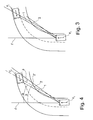
- the leftmost front headlight of the second vehicle F 2 is detected below the object angle ⁇ by the camera system of the first motor vehicle F 1 as the outermost light source.
- the vertical light-dark boundary is shifted to the direction 2 and thus has an angle ⁇ with respect to the longitudinal direction I of the first vehicle F 1 . If the right-hand headlamp of the vehicle F 1 is set to the cut-off line 2, dazzling of a driver who is to the right of the cut-off line 2 can not be avoided. Therefore, according to the invention, as in FIG. 4 represented, depending on the curve radius of the traversed right turn a Vorhaltet to the direction of the vertical cut-off line 2 according to conventional determination. This leads to a vertical light-dark boundary 2 ', which is shifted by the angle ⁇ to the right, as the light-dark boundary 2 after conventional detection. The motor vehicle driver is then left of the cut-off line after calculation according to the invention. This dazzling of the motor vehicle driver by the right headlight of the first vehicle F 1 is avoided.
- the vehicle F 1 which is equipped with a control device according to the invention, has the control device 10 according to the invention with the means for generating a control signal for the right-hand headlight or an actuating signal for the left-hand headlight.
- the control device has a first input 12 for signals of a camera system 20 and a second input 13 for a device 30 for Determine the curve radius of the traversed curve. Via the first input 12, the signal for the object angle and via the second input 13, a signal for the radius of curvature in the control device 10 is read.
- the control signals generated by the means 11 for generating the actuating signals are outputs of the control device 10 to the left headlight 40 and the right headlight 50, respectively. In the headlights 40, 50, the control signals are used by servomotors or the like for adjusting the vertical cut-off lines.
Abstract
Description
Die Erfindung betrifft eine Vorrichtung zum Steuern der vertikalen Hell-Dunkel-Grenze bei Scheinwerfern eines Kraftfahrzeugs.The invention relates to a device for controlling the vertical cut-off in headlights of a motor vehicle.
Aus der Offenlegungsschrift mit der Veröffentlichungsnummer
Um ein automatisches Einstellen der vertikalen Hell-Dunkel-Grenzen der Scheinwerfer erreichen zu können, weist der Scheinwerfer ein Sensorsystem auf. Das Sensorsystem erkennt Lichtquellen des vorausfahrenden oder entgegenkommenden Fahrzeugs, d. h. entweder die Frontscheinwerfer oder aber die Rückleuchten des Fahrzeugs.In order to be able to automatically adjust the vertical light-dark limits of the headlights, the headlight has a sensor system. The sensor system detects light sources of the preceding or oncoming vehicle, d. H. either the headlights or the taillights of the vehicle.
Weiterentwicklungen zu dem in der genannten Offenlegungsschrift
Als Grundlage für die Ermittlung der vertikalen Hell-Dunkel-Grenzen dienen die über den ersten Eingang eingelesenen Objektwinkel, unter welchen das vorausfahrende oder entgegenkommende zweite Fahrzeug ermittelt wird. Es sei an dieser Stelle darauf hingewiesen werden, dass der Objektwinkel sich in der Regel nicht auf die Kontur des zweiten Fahrzeugs im Ganzen, sondern nur auf die Position der jeweils äußersten Lichtquelle des zweiten Fahrzeugs bezieht, die von einem Sensorsystem erkannt werden. Dieses ist bei entgegenkommenden Fahrzeugen der rechte oder linke Frontscheinwerfer und bei vorausfahrenden Fahrzeugen das rechte oder linke Rücklicht. Werden keine Kurven durchfahren, befindet sich der Fahrzeugführer in der Regel immer zwischen den beiden äußeren Lichtquellen des entgegenkommenden oder vorausfahrenden Fahrzeugs.The object angles read in via the first input, under which the preceding or oncoming second vehicle is determined, serve as the basis for determining the vertical light-dark boundaries. It should be noted at this point that the object angle usually does not relate to the contour of the second vehicle as a whole, but only to the position of the respective outermost light source of the second vehicle, which are detected by a sensor system. This is the right or left headlights for oncoming vehicles and the right or left rear lights for vehicles ahead. If no curves are passed, the driver is usually always between the two outer light sources of the oncoming or preceding vehicle.
Dieses ist beim Durchfahren von Kurven jedoch nicht notwendigerweise der Fall. Insbesondere beim Durchfahren von Kurven mit sehr kleinen Radien können Situationen auftreten, in denen der Fahrzeugführer rechts von der rechten äußeren Lichtquelle des vorausfahrenden oder entgegenkommenden Fahrzeugs oder links von der linken äußeren Lichtquelle des Fahrzeugs ist. Er liegt dann innerhalb des Lichtkegels des rechten bzw. linken Scheinwerfers, d. h. links von der linken vertikalen Hell-Dunkel-Grenze bzw. rechts von der rechten vertikalen Hell-Dunkel-Grenze des Tunnels. Solche Situationen sind unerwünscht, da sie ein erhöhtes Risiko für beide Verkehrsteilnehmer darstellen.However, this is not necessarily the case when driving through curves. In particular, when driving through curves with very small radii may occur situations in which the driver is to the right of the right outer light source of the preceding or oncoming vehicle or to the left of the left outer light source of the vehicle. It then lies within the light cone of the right or left headlamp, ie to the left of the left vertical light-dark boundary and to the right of the right vertical light-dark boundary of the tunnel. Such situations are undesirable because they present an increased risk to both road users.
Der Erfindung liegt daher die Aufgabe zugrunde eine Steuervorrichtung zum Steuern der vertikalen Hell-Dunkel-Grenzen bei Scheinwerfern so zu verbessern, dass auch bei Kurvenfahrten eine Blendung weitgehend vermieden wird.The invention is therefore based on the object to improve a control device for controlling the vertical light-dark limits in headlights so that even when cornering glare is largely avoided.
Diese Aufgabe wird erfindungsgemäß dadurch gelöst, dass die Steuervorrichtung einen zweiten Eingang für ein zweites Signal aufweist, welches den Radius einer von dem Kraftfahrzeug durchfahrenen oder zu durchfahrenden Kurve anzeigt und dass das Mittel zum Erzeugen geeignet und eingerichtet ist, die Stellsignale in Abhängigkeit von dem zweiten Signal zu erzeugen. Das zweite Signal kann aus Sensorsignalen für den Lenkradeinschlagswinkel, dem Einschlagswinkel der Vorderräder, der Gierrate und/oder einer Information eines Navigationssystems oder Kamerasystems über den vor dem Kraftfahrzeug liegenden Straßenverlauf gewonnen werden.This object is achieved in that the control device has a second input for a second signal, which indicates the radius of a traversed by the motor vehicle or to be traversed curve and that the means for generating is suitable and arranged, the actuating signals in response to the second Generate signal. The second signal can be obtained from sensor signals for the steering wheel steering angle, the steering angle of the front wheels, the yaw rate and / or information of a navigation system or camera system over the road ahead of the motor vehicle.
Bei der Ermittlung der Stellsignale wird somit der Kurvenradius der von dem ersten Fahrzeug durchfahrenen oder zu durchfahrenden Kurve berücksichtigt. Damit ist es möglich, einen vom Kurvenradius der durchfahrenen oder zu durchfahrenden Kurve abhängigen Vorhalt bei der Ermittlung der Stellgrößen bzw. Stellsignale zu berücksichtigen. Dieser Vorhalt führt dazu, dass die vertikalen Hell-Dunkel-Grenzen in Kurven immer so eingestellt sind, dass eine hohe Wahrscheinlichkeit besteht, dass Fahrzeugführer die sich bezogen auf eine Rechtskurve rechts von der rechten äußeren Lichtquelle des zweiten Fahrzeugs bzw. - bezogen auf eine Linkskurve - links von der linken äußeren Lichtquelle des zweiten Fahrzeugs befinden, nicht mehr geblendet werden. Der Vorhalt ist daher sinnvollerweise umso größer, je kleiner der Kurvenradius ist.When determining the actuating signals, the curve radius of the curve traversed or to be traveled by the first vehicle is thus taken into account. This makes it possible to take into account a derivative of the curve radius of the traversed or traversed curve derivative in the determination of the control variables or control signals. This lead means that the vertical cut-offs in curves are always set so that there is a high probability that drivers are referring to a right turn right of the right outer light source of the second vehicle or - in relation to a left turn - Left of the left outer light source of the second vehicle are no longer blinded. The derivative is therefore meaningfully larger, the smaller the radius of curvature.
Eine erfindungsgemäße Steuervorrichtung kann so eingerichtet sein, dass das Mittel zum Erzeugen für dem rechten Scheinwerfer und/oder den linken Scheinwerfer in Abhängigkeit von dem ersten Signal, d. h. in Abhängigkeit von dem Objektwinkel, eine erste Zwischengröße erzeugt. Diese ersten Zwischengrößen können den Stellgrößen entsprechen, die bei herkömmlichen Steuervorrichtungen für Scheinwerfer mit adaptierbaren vertikalen Hell-Dunkel-Grenzen für die gegebenen Objektwinkel ermittelt werden.A control device according to the invention can be set up such that the means for generating for the right-hand headlight and / or the left-hand headlight generates a first intermediate variable as a function of the first signal, ie as a function of the object angle. These first intermediate variables may correspond to the manipulated variables which are determined in the case of conventional control devices for headlamps with adaptable vertical light-dark boundaries for the given object angles.
Gemäß der Erfindung kann das Mittel zum Erzeugen geeignet und eingerichtet sein, eine zweite Zwischengröße für den rechten Scheinwerfer und/oder für den linken Scheinwerfer in Abhängigkeit von dem zweiten Signal zu erzeugen. Diese zweite Zwischengröße kann dem Vorhalt entsprechen, der mit dem Winkel der vertikalen Hell-Dunkel-Grenze nach herkömmlicher Ermittlung summiert wird.According to the invention, the means for generating may be adapted and arranged to generate a second intermediate size for the right-hand headlamp and / or for the left-hand headlamp in response to the second signal. This second intermediate quantity may correspond to the derivative which is summed with the angle of the vertical light-dark boundary after conventional determination.
Das Mittel zum Erzeugen einer erfindungsgemäßen Steuervorrichtung kann die Stellsignale in Abhängigkeit der ersten Zwischengröße und der zweiten Zwischengröße erzeugen. Beide Zwischengrößen können insbesondere mittels des Mittels zum Erzeugen addiert werden.The means for generating a control device according to the invention can generate the actuating signals as a function of the first intermediate variable and the second intermediate variable. Both intermediate variables can be added in particular by means of the generating means.
Beispielsweise kann das Mittel (11) zum Erzeugen die zweite Zwischengröße (δ) für den rechten bzw. linken Scheinwerfer (50 bzw. 40) folgendermaßen bestimmen:
- δ = [0°,2°] für R > 0 m (Rechtskurve) und α > 0°,
- δ = [-2°,0°] für R < 0 m (Linkskurve) und α < 0° und
- in allen übrigen Fällen δ = 0
- δ = [0 °, 2 °] for R> 0 m (right-hand curve) and α> 0 °,
- δ = [-2 °, 0 °] for R <0 m (left-hand curve) and α <0 ° and
- in all other cases δ = 0
Anhand der beigefügten Zeichnungen wird die Erfindung nachfolgend näher erläutert. Dabei zeigt:
- Fig. 1
- eine Draufsicht auf eine schematisch dargestellte Fahrsituation zweier einander folgender Fahrzeuge ohne Berücksichtigung der Erfindung,
- Fig. 2
- die Fahrsituation aus
Figur 1 - Fig. 3
- eine Fahrsituation in Draufsicht mit zwei einander entgegenkommenden Fahrzeugen ohne Berücksichtigung der Erfindung,
- Fig. 4
- die Fahrsituation gemäß
Figur 3 mit Berücksichtigung der Erfindung, - Fig. 5
- ein Blockschaltbild einer Anordnung mit einer erfindungsgemäßen Steuer- vorrichtung.
- Fig. 1
- a plan view of a schematically illustrated driving situation of two consecutive vehicles without consideration of the invention,
- Fig. 2
- the driving situation
FIG. 1 with consideration of the invention, - Fig. 3
- a driving situation in plan view with two oncoming vehicles without consideration of the invention,
- Fig. 4
- the driving situation according to
FIG. 3 with consideration of the invention, - Fig. 5
- a block diagram of an arrangement with a control device according to the invention.
In der in der
Durch das Verschieben der vertikalen Hell-Dunkel-Grenze bei entsprechend dem Objektwinkel α bzw. der Richtung 1 der äußersten Lichtquelle wird eine weitgehende Entblendung des vorausfahrenden zweiten Fahrzeugs F2 erreicht.By shifting the vertical light-dark boundary in accordance with the object angle α or the
Allerdings erfolgt keine vollständige Entblendung, wie sich aus der in der
Durch die Erfindung wird eine derartige Blendung bei einer Kurvenfahrt vermieden. Dieses wird dadurch erreicht, dass bei einer Kurvenfahrt durch eine Rechtskurve auf die aufgrund des Objektwinkels ermittelte vertikale Hell-Dunkel-Grenze 2 ein Vorhalt gegeben wird. Die Richtung der vertikalen Hell-Dunkel-Grenze wird um den Vorhalt, in der
Eine ähnliche Situation ergibt sich, wenn, wie in
Ist das erste Fahrzeug F1 mit einer herkömmlichen Steuervorrichtung zum Einstellen der vertikalen Hell-Dunkel-Grenze ausgestattet, wird die vertikale Hell-Dunkel-Grenze auf die Richtung 2 verschoben und hat somit einen Winkel β bezogen auf die Längsrichtung I des ersten Fahrzeugs F1. Ist der rechte Scheinwerfer des Fahrzeugs F1 auf die Hell-Dunkel-Grenze 2 eingestellt, kann eine Blendung eines Fahrzeugführers, der sich rechts von der Hell-Dunkel-Grenze 2 befindet nicht vermieden werden. Erfindungsgemäß wird daher, wie in
Das Fahrzeug F1, das mit einer erfindungsgemäßen Steuervorrichtung ausgestattet ist, weist die erfindungsgemäße Steuervorrichtung 10 mit dem Mittel zum Erzeugen eines Stellsignals für den rechten Scheinwerfer bzw. eines Stellsignals für den linken Scheinwerfer auf. Die Steuervorrichtung weist einen ersten Eingang 12 für Signale eines Kamerasystems 20 und einen zweiten Eingang 13 für eine Vorrichtung 30 zum Ermitteln des Kurvenradius der durchfahrenen Kurve auf. Über den ersten Eingang 12 wird das Signal für den Objektwinkel und über den zweiten Eingang 13 ein Signal für den Kurvenradius in die Steuervorrichtung 10 eingelesen. Die von dem Mittel 11 zum Erzeugen der Stellsignale erzeugten Stellsignale werden Ausgänge der Steuervorrichtung 10 an den linken Scheinwerfer 40 bzw. den rechten Scheinwerfer 50 gegeben. In den Scheinwerfern 40, 50 werden die Stellsignale durch Stellmotoren oder dergleichen zum Einstellen der vertikalen Hell-Dunkel-Grenzen benutzt.The vehicle F 1 , which is equipped with a control device according to the invention, has the
- F1 F 1
- Kraftfahrzeugmotor vehicle
- F2 F 2
- vorausfahrendes Fahrzeugpreceding vehicle
- II
- Längsachselongitudinal axis
- αα
- Objektwinkelobject angle
- ββ
- Winkel der Hell-Dunkel-GrenzeAngle of the cut-off line
- β'β '
- verschobener Winkel der Hell-Dunkel-Grenzeshifted angle of the cut-off line
- δδ
- Vorhaltderivative
- 11
- Objektrichtungobject direction
- 22
- Hell-Dunkel-GrenzeLight-off
- 1010
- Steuervorrichtungcontrol device
- 1111
- Mittel zum Erzeugen eines StellsignalsMeans for generating a control signal
- 1212
- erster Eingangfirst entrance
- 1313
- zweiter Eingangsecond entrance
- 2020
- Kamerasystemcamera system
- 3030
- Vorrichtung zum Ermitteln des KurvenradiusDevice for determining the radius of curvature
- 4040
- linker Scheinwerferleft headlight
- 5050
- rechter Scheinwerferright headlight
Claims (7)
Applications Claiming Priority (1)
| Application Number | Priority Date | Filing Date | Title |
|---|---|---|---|
| DE200810038536 DE102008038536A1 (en) | 2008-08-20 | 2008-08-20 | Method and device for controlling the vertical cut-off for headlamps |
Publications (2)
| Publication Number | Publication Date |
|---|---|
| EP2156983A1 true EP2156983A1 (en) | 2010-02-24 |
| EP2156983B1 EP2156983B1 (en) | 2012-06-20 |
Family
ID=41268319
Family Applications (1)
| Application Number | Title | Priority Date | Filing Date |
|---|---|---|---|
| EP09165945A Active EP2156983B1 (en) | 2008-08-20 | 2009-07-21 | Method and device for controlling the vertical cut-off line of headlamps |
Country Status (2)
| Country | Link |
|---|---|
| EP (1) | EP2156983B1 (en) |
| DE (1) | DE102008038536A1 (en) |
Cited By (11)
| Publication number | Priority date | Publication date | Assignee | Title |
|---|---|---|---|---|
| EP2281719A1 (en) * | 2009-08-04 | 2011-02-09 | Koito Manufacturing Co., Ltd. | Light distribution control system for automotive headlamp |
| EP2279908A3 (en) * | 2009-07-29 | 2011-07-20 | Koito Manufacturing Co., Ltd. | Automotive headlamp apparatus having swivel function of lamp unit |
| JP2013043623A (en) * | 2011-08-26 | 2013-03-04 | Stanley Electric Co Ltd | Lighting control device of vehicle headlamp, and vehicle headlamp system |
| EP2636946A3 (en) * | 2012-03-08 | 2014-04-02 | Stanley Electric Co., Ltd. | Headlight controller, optical unit and vehicle headlight |
| FR2999128A1 (en) * | 2012-12-11 | 2014-06-13 | Valeo Vision | METHOD AND DEVICE FOR CONTROLLING A LIGHT BEAM |
| WO2015159589A1 (en) * | 2014-04-18 | 2015-10-22 | 株式会社デンソー | Vehicle-headlight control device |
| EP2982540A1 (en) * | 2014-08-08 | 2016-02-10 | Toyota Jidosha Kabushiki Kaisha | Irradiation system |
| FR3031480A1 (en) * | 2015-01-12 | 2016-07-15 | Valeo Schalter & Sensoren Gmbh | METHOD FOR ADJUSTING A PROJECTOR OF A MOTOR VEHICLE, DEVICE FOR ADJUSTING SUCH A PROJECTOR, AND MOTOR VEHICLE COMPRISING SUCH A DEVICE |
| WO2017163414A1 (en) * | 2016-03-25 | 2017-09-28 | 三菱電機株式会社 | Light distribution control device, light distribution control method, and light distribution control program |
| EP3569445A1 (en) * | 2018-05-18 | 2019-11-20 | Toyota Jidosha Kabushiki Kaisha | Vehicle front headlight device |
| WO2020008062A1 (en) * | 2018-07-06 | 2020-01-09 | Valeo Vision | Adaptation of a motor vehicle high-beam function |
Families Citing this family (4)
| Publication number | Priority date | Publication date | Assignee | Title |
|---|---|---|---|---|
| DE102008047025A1 (en) | 2008-09-13 | 2010-03-18 | Hella Kgaa Hueck & Co. | Method and apparatus for controlling vertical cut-offs on headlamps within a swivel range |
| DE102010035636A1 (en) * | 2010-08-27 | 2012-03-01 | Hella Kgaa Hueck & Co. | Device and method for changing from a high beam distribution to an object to blinding blinding light distribution |
| DE102011050535B4 (en) * | 2011-05-20 | 2023-09-28 | HELLA GmbH & Co. KGaA | Headlight arrangement consisting of a right and a left headlight comprising a light source matrix and a control device for controlling the headlights |
| DE102011050532B4 (en) * | 2011-05-20 | 2020-03-12 | HELLA GmbH & Co. KGaA | Control device and method for controlling vehicle headlights |
Citations (9)
| Publication number | Priority date | Publication date | Assignee | Title |
|---|---|---|---|---|
| DE2144197A1 (en) | 1970-09-18 | 1972-03-09 | Lucas Ltd Joseph | Lighting device for road vehicles |
| EP0869031A2 (en) * | 1997-04-04 | 1998-10-07 | Robert Bosch Gmbh | Device for controlling the light beam and/or the lighting direction |
| US20050052879A1 (en) * | 2003-09-02 | 2005-03-10 | Gerd Bahnmuller | Illuminating device for a vehicle for realizing an asymmetrical light distribution |
| DE102006043281A1 (en) * | 2006-09-14 | 2008-03-27 | Hella Kgaa Hueck & Co. | Projection headlight device for vehicle, has two focal points comprising shell type reflector, light source and lens with diaphragm shaft, which is arranged between the lens and the reflector |
| DE102007045150A1 (en) * | 2006-09-27 | 2008-04-17 | Volkswagen Ag | Headlight arrangement controlling method for motor vehicle, involves modifying position of diaphragm arrangement, when road user is detected so that central region with small light range is formed and surrounded by regions with larger range |
| US20080106886A1 (en) * | 2006-10-31 | 2008-05-08 | Toshio Sugimoto | Apparatus for controlling swivel angles of on-vehicle headlights |
| JP2009046118A (en) * | 2007-07-24 | 2009-03-05 | Koito Mfg Co Ltd | Headlamp system for vehicle |
| EP2060441A1 (en) * | 2007-11-13 | 2009-05-20 | Valeo Vision | Method for automatically adjusting the light beam of a headlight device to road traffic |
| EP2060442A2 (en) * | 2007-11-16 | 2009-05-20 | Valeo Vision | Lighting device for an automobile |
Family Cites Families (1)
| Publication number | Priority date | Publication date | Assignee | Title |
|---|---|---|---|---|
| DE102008014182A1 (en) * | 2008-03-14 | 2009-09-17 | Daimler Ag | Method for driving light control of a vehicle |
-
2008
- 2008-08-20 DE DE200810038536 patent/DE102008038536A1/en not_active Ceased
-
2009
- 2009-07-21 EP EP09165945A patent/EP2156983B1/en active Active
Patent Citations (9)
| Publication number | Priority date | Publication date | Assignee | Title |
|---|---|---|---|---|
| DE2144197A1 (en) | 1970-09-18 | 1972-03-09 | Lucas Ltd Joseph | Lighting device for road vehicles |
| EP0869031A2 (en) * | 1997-04-04 | 1998-10-07 | Robert Bosch Gmbh | Device for controlling the light beam and/or the lighting direction |
| US20050052879A1 (en) * | 2003-09-02 | 2005-03-10 | Gerd Bahnmuller | Illuminating device for a vehicle for realizing an asymmetrical light distribution |
| DE102006043281A1 (en) * | 2006-09-14 | 2008-03-27 | Hella Kgaa Hueck & Co. | Projection headlight device for vehicle, has two focal points comprising shell type reflector, light source and lens with diaphragm shaft, which is arranged between the lens and the reflector |
| DE102007045150A1 (en) * | 2006-09-27 | 2008-04-17 | Volkswagen Ag | Headlight arrangement controlling method for motor vehicle, involves modifying position of diaphragm arrangement, when road user is detected so that central region with small light range is formed and surrounded by regions with larger range |
| US20080106886A1 (en) * | 2006-10-31 | 2008-05-08 | Toshio Sugimoto | Apparatus for controlling swivel angles of on-vehicle headlights |
| JP2009046118A (en) * | 2007-07-24 | 2009-03-05 | Koito Mfg Co Ltd | Headlamp system for vehicle |
| EP2060441A1 (en) * | 2007-11-13 | 2009-05-20 | Valeo Vision | Method for automatically adjusting the light beam of a headlight device to road traffic |
| EP2060442A2 (en) * | 2007-11-16 | 2009-05-20 | Valeo Vision | Lighting device for an automobile |
Cited By (16)
| Publication number | Priority date | Publication date | Assignee | Title |
|---|---|---|---|---|
| US9956901B2 (en) | 2009-07-29 | 2018-05-01 | Koito Manufacturing Co., Ltd. | Automotive headlamp apparatus having swivel function of lamp unit |
| EP2279908A3 (en) * | 2009-07-29 | 2011-07-20 | Koito Manufacturing Co., Ltd. | Automotive headlamp apparatus having swivel function of lamp unit |
| EP2281719A1 (en) * | 2009-08-04 | 2011-02-09 | Koito Manufacturing Co., Ltd. | Light distribution control system for automotive headlamp |
| JP2013043623A (en) * | 2011-08-26 | 2013-03-04 | Stanley Electric Co Ltd | Lighting control device of vehicle headlamp, and vehicle headlamp system |
| EP2636946A3 (en) * | 2012-03-08 | 2014-04-02 | Stanley Electric Co., Ltd. | Headlight controller, optical unit and vehicle headlight |
| US9041808B2 (en) | 2012-03-08 | 2015-05-26 | Stanley Electric Co., Ltd. | Headlight controller, optical unit and vehicle headlight |
| FR2999128A1 (en) * | 2012-12-11 | 2014-06-13 | Valeo Vision | METHOD AND DEVICE FOR CONTROLLING A LIGHT BEAM |
| EP2743129A1 (en) * | 2012-12-11 | 2014-06-18 | Valeo Vision | Method and device for controlling a light beam |
| WO2015159589A1 (en) * | 2014-04-18 | 2015-10-22 | 株式会社デンソー | Vehicle-headlight control device |
| US11603033B2 (en) | 2014-04-18 | 2023-03-14 | Denso Corporation | Control apparatus for vehicle headlight |
| EP2982540A1 (en) * | 2014-08-08 | 2016-02-10 | Toyota Jidosha Kabushiki Kaisha | Irradiation system |
| FR3031480A1 (en) * | 2015-01-12 | 2016-07-15 | Valeo Schalter & Sensoren Gmbh | METHOD FOR ADJUSTING A PROJECTOR OF A MOTOR VEHICLE, DEVICE FOR ADJUSTING SUCH A PROJECTOR, AND MOTOR VEHICLE COMPRISING SUCH A DEVICE |
| WO2017163414A1 (en) * | 2016-03-25 | 2017-09-28 | 三菱電機株式会社 | Light distribution control device, light distribution control method, and light distribution control program |
| EP3569445A1 (en) * | 2018-05-18 | 2019-11-20 | Toyota Jidosha Kabushiki Kaisha | Vehicle front headlight device |
| WO2020008062A1 (en) * | 2018-07-06 | 2020-01-09 | Valeo Vision | Adaptation of a motor vehicle high-beam function |
| FR3083494A1 (en) * | 2018-07-06 | 2020-01-10 | Valeo Vision | ADAPTATION OF A HIGH LIGHT FUNCTION OF A MOTOR VEHICLE |
Also Published As
| Publication number | Publication date |
|---|---|
| DE102008038536A1 (en) | 2010-02-25 |
| EP2156983B1 (en) | 2012-06-20 |
Similar Documents
| Publication | Publication Date | Title |
|---|---|---|
| EP2156983B1 (en) | Method and device for controlling the vertical cut-off line of headlamps | |
| EP2156984B1 (en) | Method and device for controlling the vertical cut-off line of headlamps | |
| EP2338731B1 (en) | Control device for controlling vehicle headlights to generate a light distribution with trackable vertical bright-dark boundaries | |
| EP1880931A2 (en) | Motor vehicle with rear lighting device and deployable spoiler | |
| DE102013016761A1 (en) | Method for operating headlamps of a motor vehicle, headlight system and motor vehicle | |
| EP2119592A1 (en) | Control device to control vehicle's main headlights | |
| DE102009057391A1 (en) | Method for driving light control of vehicle, involves adjusting left swivel head light and right swivel head light independently to each other for adjustment of light distribution | |
| EP2326533B1 (en) | Method and device for controlling vertical light-dark limits in headlights within a tilt range | |
| DE102014018995A1 (en) | Method for operating a headlight and motor vehicle headlights | |
| DE102014204791A1 (en) | Automatic control of the headlights of a vehicle | |
| AT517415B1 (en) | Control device for a lighting device of a motor vehicle and method for controlling such a lighting device | |
| EP2384932A2 (en) | Method for predictive control of an adaptive headlamp and motor vehicle | |
| DE102008039091A1 (en) | Method for processing camera data for variable controlling headlights of vehicle, involves detecting group of objects and light sources by camera | |
| DE102014110628A1 (en) | Method and device for driving a vehicle headlight | |
| DE102013109071A1 (en) | Arrangement and method for blinding vehicles with the aid of at least one near field sensor device | |
| EP2119593A1 (en) | Control device to control and/or regulate a vertical cut-off line for a vehicle's headlights | |
| WO2009053457A1 (en) | Device for controlling and/or regulating the activation or deactivation of the automatic setting of the light-dark boundary of a motor vehicle headlight or turning the high beams on and off in motor vehicle headlights | |
| DE102016208831B4 (en) | Method and device for driving light control | |
| EP2576290B1 (en) | Control unit and method for preventing dazzling of vehicles during turning manoeuvres | |
| DE102014006598A1 (en) | Method for operating a driver assistance system of a motor vehicle, driver assistance system and motor vehicle | |
| DE102015221127A1 (en) | Control unit for controlling or regulating at least one lighting device and motor vehicle with such a control device | |
| EP2052910B1 (en) | Assembly to control and/or regulate the beam cut-off of motor vehicle headlamps | |
| DE102006020960A1 (en) | Headlights for vehicles | |
| WO2019042853A1 (en) | Method for controlling at least one main headlamp of a lighting unit of a vehicle, lighting unit, computer programme product, and computer-readable medium | |
| WO2008025435A1 (en) | Method and device for switching over the illumination characteristics of a headlight for left-hand or right-hand traffic |
Legal Events
| Date | Code | Title | Description |
|---|---|---|---|
| PUAI | Public reference made under article 153(3) epc to a published international application that has entered the european phase |
Free format text: ORIGINAL CODE: 0009012 |
|
| AK | Designated contracting states |
Kind code of ref document: A1 Designated state(s): AT BE BG CH CY CZ DE DK EE ES FI FR GB GR HR HU IE IS IT LI LT LU LV MC MK MT NL NO PL PT RO SE SI SK SM TR |
|
| AX | Request for extension of the european patent |
Extension state: AL BA RS |
|
| 17P | Request for examination filed |
Effective date: 20100810 |
|
| 17Q | First examination report despatched |
Effective date: 20100831 |
|
| GRAP | Despatch of communication of intention to grant a patent |
Free format text: ORIGINAL CODE: EPIDOSNIGR1 |
|
| GRAS | Grant fee paid |
Free format text: ORIGINAL CODE: EPIDOSNIGR3 |
|
| GRAA | (expected) grant |
Free format text: ORIGINAL CODE: 0009210 |
|
| AK | Designated contracting states |
Kind code of ref document: B1 Designated state(s): AT BE BG CH CY CZ DE DK EE ES FI FR GB GR HR HU IE IS IT LI LT LU LV MC MK MT NL NO PL PT RO SE SI SK SM TR |
|
| REG | Reference to a national code |
Ref country code: GB Ref legal event code: FG4D Free format text: NOT ENGLISH |
|
| REG | Reference to a national code |
Ref country code: CH Ref legal event code: EP |
|
| REG | Reference to a national code |
Ref country code: AT Ref legal event code: REF Ref document number: 562854 Country of ref document: AT Kind code of ref document: T Effective date: 20120715 |
|
| REG | Reference to a national code |
Ref country code: IE Ref legal event code: FG4D Free format text: LANGUAGE OF EP DOCUMENT: GERMAN |
|
| REG | Reference to a national code |
Ref country code: DE Ref legal event code: R096 Ref document number: 502009003839 Country of ref document: DE Effective date: 20120816 |
|
| PG25 | Lapsed in a contracting state [announced via postgrant information from national office to epo] |
Ref country code: LT Free format text: LAPSE BECAUSE OF FAILURE TO SUBMIT A TRANSLATION OF THE DESCRIPTION OR TO PAY THE FEE WITHIN THE PRESCRIBED TIME-LIMIT Effective date: 20120620 Ref country code: NO Free format text: LAPSE BECAUSE OF FAILURE TO SUBMIT A TRANSLATION OF THE DESCRIPTION OR TO PAY THE FEE WITHIN THE PRESCRIBED TIME-LIMIT Effective date: 20120920 Ref country code: FI Free format text: LAPSE BECAUSE OF FAILURE TO SUBMIT A TRANSLATION OF THE DESCRIPTION OR TO PAY THE FEE WITHIN THE PRESCRIBED TIME-LIMIT Effective date: 20120620 Ref country code: SE Free format text: LAPSE BECAUSE OF FAILURE TO SUBMIT A TRANSLATION OF THE DESCRIPTION OR TO PAY THE FEE WITHIN THE PRESCRIBED TIME-LIMIT Effective date: 20120620 |
|
| REG | Reference to a national code |
Ref country code: NL Ref legal event code: VDEP Effective date: 20120620 |
|
| REG | Reference to a national code |
Ref country code: LT Ref legal event code: MG4D Effective date: 20120627 |
|
| PG25 | Lapsed in a contracting state [announced via postgrant information from national office to epo] |
Ref country code: HR Free format text: LAPSE BECAUSE OF FAILURE TO SUBMIT A TRANSLATION OF THE DESCRIPTION OR TO PAY THE FEE WITHIN THE PRESCRIBED TIME-LIMIT Effective date: 20120620 Ref country code: GR Free format text: LAPSE BECAUSE OF FAILURE TO SUBMIT A TRANSLATION OF THE DESCRIPTION OR TO PAY THE FEE WITHIN THE PRESCRIBED TIME-LIMIT Effective date: 20120921 Ref country code: LV Free format text: LAPSE BECAUSE OF FAILURE TO SUBMIT A TRANSLATION OF THE DESCRIPTION OR TO PAY THE FEE WITHIN THE PRESCRIBED TIME-LIMIT Effective date: 20120620 Ref country code: SI Free format text: LAPSE BECAUSE OF FAILURE TO SUBMIT A TRANSLATION OF THE DESCRIPTION OR TO PAY THE FEE WITHIN THE PRESCRIBED TIME-LIMIT Effective date: 20120620 |
|
| BERE | Be: lapsed |
Owner name: HELLA KGAA HUECK & CO. Effective date: 20120731 |
|
| PG25 | Lapsed in a contracting state [announced via postgrant information from national office to epo] |
Ref country code: SK Free format text: LAPSE BECAUSE OF FAILURE TO SUBMIT A TRANSLATION OF THE DESCRIPTION OR TO PAY THE FEE WITHIN THE PRESCRIBED TIME-LIMIT Effective date: 20120620 Ref country code: RO Free format text: LAPSE BECAUSE OF FAILURE TO SUBMIT A TRANSLATION OF THE DESCRIPTION OR TO PAY THE FEE WITHIN THE PRESCRIBED TIME-LIMIT Effective date: 20120620 Ref country code: EE Free format text: LAPSE BECAUSE OF FAILURE TO SUBMIT A TRANSLATION OF THE DESCRIPTION OR TO PAY THE FEE WITHIN THE PRESCRIBED TIME-LIMIT Effective date: 20120620 Ref country code: IS Free format text: LAPSE BECAUSE OF FAILURE TO SUBMIT A TRANSLATION OF THE DESCRIPTION OR TO PAY THE FEE WITHIN THE PRESCRIBED TIME-LIMIT Effective date: 20121020 Ref country code: CZ Free format text: LAPSE BECAUSE OF FAILURE TO SUBMIT A TRANSLATION OF THE DESCRIPTION OR TO PAY THE FEE WITHIN THE PRESCRIBED TIME-LIMIT Effective date: 20120620 Ref country code: CY Free format text: LAPSE BECAUSE OF FAILURE TO SUBMIT A TRANSLATION OF THE DESCRIPTION OR TO PAY THE FEE WITHIN THE PRESCRIBED TIME-LIMIT Effective date: 20120620 |
|
| PG25 | Lapsed in a contracting state [announced via postgrant information from national office to epo] |
Ref country code: MC Free format text: LAPSE BECAUSE OF NON-PAYMENT OF DUE FEES Effective date: 20120731 Ref country code: PT Free format text: LAPSE BECAUSE OF FAILURE TO SUBMIT A TRANSLATION OF THE DESCRIPTION OR TO PAY THE FEE WITHIN THE PRESCRIBED TIME-LIMIT Effective date: 20121022 Ref country code: IT Free format text: LAPSE BECAUSE OF FAILURE TO SUBMIT A TRANSLATION OF THE DESCRIPTION OR TO PAY THE FEE WITHIN THE PRESCRIBED TIME-LIMIT Effective date: 20120620 Ref country code: PL Free format text: LAPSE BECAUSE OF FAILURE TO SUBMIT A TRANSLATION OF THE DESCRIPTION OR TO PAY THE FEE WITHIN THE PRESCRIBED TIME-LIMIT Effective date: 20120620 Ref country code: MK Free format text: LAPSE BECAUSE OF FAILURE TO SUBMIT A TRANSLATION OF THE DESCRIPTION OR TO PAY THE FEE WITHIN THE PRESCRIBED TIME-LIMIT Effective date: 20120620 |
|
| PG25 | Lapsed in a contracting state [announced via postgrant information from national office to epo] |
Ref country code: NL Free format text: LAPSE BECAUSE OF FAILURE TO SUBMIT A TRANSLATION OF THE DESCRIPTION OR TO PAY THE FEE WITHIN THE PRESCRIBED TIME-LIMIT Effective date: 20120620 |
|
| PLBE | No opposition filed within time limit |
Free format text: ORIGINAL CODE: 0009261 |
|
| STAA | Information on the status of an ep patent application or granted ep patent |
Free format text: STATUS: NO OPPOSITION FILED WITHIN TIME LIMIT |
|
| PG25 | Lapsed in a contracting state [announced via postgrant information from national office to epo] |
Ref country code: ES Free format text: LAPSE BECAUSE OF FAILURE TO SUBMIT A TRANSLATION OF THE DESCRIPTION OR TO PAY THE FEE WITHIN THE PRESCRIBED TIME-LIMIT Effective date: 20121001 Ref country code: DK Free format text: LAPSE BECAUSE OF FAILURE TO SUBMIT A TRANSLATION OF THE DESCRIPTION OR TO PAY THE FEE WITHIN THE PRESCRIBED TIME-LIMIT Effective date: 20120620 |
|
| REG | Reference to a national code |
Ref country code: IE Ref legal event code: MM4A |
|
| 26N | No opposition filed |
Effective date: 20130321 |
|
| PG25 | Lapsed in a contracting state [announced via postgrant information from national office to epo] |
Ref country code: BE Free format text: LAPSE BECAUSE OF NON-PAYMENT OF DUE FEES Effective date: 20120731 |
|
| REG | Reference to a national code |
Ref country code: DE Ref legal event code: R097 Ref document number: 502009003839 Country of ref document: DE Effective date: 20130321 |
|
| PG25 | Lapsed in a contracting state [announced via postgrant information from national office to epo] |
Ref country code: BG Free format text: LAPSE BECAUSE OF FAILURE TO SUBMIT A TRANSLATION OF THE DESCRIPTION OR TO PAY THE FEE WITHIN THE PRESCRIBED TIME-LIMIT Effective date: 20120920 Ref country code: MT Free format text: LAPSE BECAUSE OF FAILURE TO SUBMIT A TRANSLATION OF THE DESCRIPTION OR TO PAY THE FEE WITHIN THE PRESCRIBED TIME-LIMIT Effective date: 20120620 Ref country code: IE Free format text: LAPSE BECAUSE OF NON-PAYMENT OF DUE FEES Effective date: 20120721 |
|
| REG | Reference to a national code |
Ref country code: CH Ref legal event code: PL |
|
| PG25 | Lapsed in a contracting state [announced via postgrant information from national office to epo] |
Ref country code: CH Free format text: LAPSE BECAUSE OF NON-PAYMENT OF DUE FEES Effective date: 20130731 Ref country code: LI Free format text: LAPSE BECAUSE OF NON-PAYMENT OF DUE FEES Effective date: 20130731 Ref country code: TR Free format text: LAPSE BECAUSE OF FAILURE TO SUBMIT A TRANSLATION OF THE DESCRIPTION OR TO PAY THE FEE WITHIN THE PRESCRIBED TIME-LIMIT Effective date: 20120620 |
|
| PG25 | Lapsed in a contracting state [announced via postgrant information from national office to epo] |
Ref country code: LU Free format text: LAPSE BECAUSE OF NON-PAYMENT OF DUE FEES Effective date: 20120721 Ref country code: SM Free format text: LAPSE BECAUSE OF FAILURE TO SUBMIT A TRANSLATION OF THE DESCRIPTION OR TO PAY THE FEE WITHIN THE PRESCRIBED TIME-LIMIT Effective date: 20120620 |
|
| PG25 | Lapsed in a contracting state [announced via postgrant information from national office to epo] |
Ref country code: HU Free format text: LAPSE BECAUSE OF FAILURE TO SUBMIT A TRANSLATION OF THE DESCRIPTION OR TO PAY THE FEE WITHIN THE PRESCRIBED TIME-LIMIT Effective date: 20090721 |
|
| REG | Reference to a national code |
Ref country code: AT Ref legal event code: MM01 Ref document number: 562854 Country of ref document: AT Kind code of ref document: T Effective date: 20140721 |
|
| PG25 | Lapsed in a contracting state [announced via postgrant information from national office to epo] |
Ref country code: AT Free format text: LAPSE BECAUSE OF NON-PAYMENT OF DUE FEES Effective date: 20140721 |
|
| REG | Reference to a national code |
Ref country code: FR Ref legal event code: PLFP Year of fee payment: 8 |
|
| REG | Reference to a national code |
Ref country code: FR Ref legal event code: PLFP Year of fee payment: 9 |
|
| REG | Reference to a national code |
Ref country code: DE Ref legal event code: R081 Ref document number: 502009003839 Country of ref document: DE Owner name: HELLA GMBH & CO. KGAA, DE Free format text: FORMER OWNER: HELLA KGAA HUECK & CO., 59557 LIPPSTADT, DE |
|
| REG | Reference to a national code |
Ref country code: FR Ref legal event code: PLFP Year of fee payment: 10 |
|
| PGFP | Annual fee paid to national office [announced via postgrant information from national office to epo] |
Ref country code: GB Payment date: 20200708 Year of fee payment: 12 |
|
| GBPC | Gb: european patent ceased through non-payment of renewal fee |
Effective date: 20210721 |
|
| PG25 | Lapsed in a contracting state [announced via postgrant information from national office to epo] |
Ref country code: GB Free format text: LAPSE BECAUSE OF NON-PAYMENT OF DUE FEES Effective date: 20210721 |
|
| PGFP | Annual fee paid to national office [announced via postgrant information from national office to epo] |
Ref country code: FR Payment date: 20230620 Year of fee payment: 15 |
|
| PGFP | Annual fee paid to national office [announced via postgrant information from national office to epo] |
Ref country code: DE Payment date: 20230531 Year of fee payment: 15 |