EP2156880A1 - Process for separating liquid mixtures - Google Patents
Process for separating liquid mixtures Download PDFInfo
- Publication number
- EP2156880A1 EP2156880A1 EP08162585A EP08162585A EP2156880A1 EP 2156880 A1 EP2156880 A1 EP 2156880A1 EP 08162585 A EP08162585 A EP 08162585A EP 08162585 A EP08162585 A EP 08162585A EP 2156880 A1 EP2156880 A1 EP 2156880A1
- Authority
- EP
- European Patent Office
- Prior art keywords
- stream
- membrane
- process according
- vaporizing
- vapor
- Prior art date
- Legal status (The legal status is an assumption and is not a legal conclusion. Google has not performed a legal analysis and makes no representation as to the accuracy of the status listed.)
- Withdrawn
Links
- 238000000034 method Methods 0.000 title claims abstract description 55
- 239000007788 liquid Substances 0.000 title claims abstract description 48
- 230000008569 process Effects 0.000 title claims abstract description 41
- 239000000203 mixture Substances 0.000 title claims abstract description 29
- 239000012528 membrane Substances 0.000 claims abstract description 95
- 230000008016 vaporization Effects 0.000 claims abstract description 37
- 238000000926 separation method Methods 0.000 claims abstract description 23
- 239000012465 retentate Substances 0.000 claims abstract description 22
- 238000001816 cooling Methods 0.000 claims abstract description 21
- 150000001875 compounds Chemical class 0.000 claims abstract description 16
- LRHPLDYGYMQRHN-UHFFFAOYSA-N N-Butanol Chemical compound CCCCO LRHPLDYGYMQRHN-UHFFFAOYSA-N 0.000 claims description 28
- XLYOFNOQVPJJNP-UHFFFAOYSA-N water Substances O XLYOFNOQVPJJNP-UHFFFAOYSA-N 0.000 claims description 15
- LFQSCWFLJHTTHZ-UHFFFAOYSA-N Ethanol Chemical compound CCO LFQSCWFLJHTTHZ-UHFFFAOYSA-N 0.000 claims description 14
- 239000012466 permeate Substances 0.000 claims description 14
- CSCPPACGZOOCGX-UHFFFAOYSA-N Acetone Chemical compound CC(C)=O CSCPPACGZOOCGX-UHFFFAOYSA-N 0.000 claims description 10
- 239000002826 coolant Substances 0.000 claims description 7
- LYCAIKOWRPUZTN-UHFFFAOYSA-N Ethylene glycol Chemical compound OCCO LYCAIKOWRPUZTN-UHFFFAOYSA-N 0.000 claims description 6
- PEDCQBHIVMGVHV-UHFFFAOYSA-N Glycerine Chemical compound OCC(O)CO PEDCQBHIVMGVHV-UHFFFAOYSA-N 0.000 claims description 6
- 238000009833 condensation Methods 0.000 claims description 6
- 230000005494 condensation Effects 0.000 claims description 6
- 238000000855 fermentation Methods 0.000 claims description 6
- 230000004151 fermentation Effects 0.000 claims description 6
- 230000002209 hydrophobic effect Effects 0.000 claims description 6
- 150000002894 organic compounds Chemical class 0.000 claims description 5
- 125000006850 spacer group Chemical group 0.000 claims description 5
- 238000005086 pumping Methods 0.000 claims description 4
- 239000000919 ceramic Substances 0.000 claims description 3
- 239000012510 hollow fiber Substances 0.000 claims description 3
- 239000004941 mixed matrix membrane Substances 0.000 claims description 3
- 238000005373 pervaporation Methods 0.000 abstract description 11
- 230000004907 flux Effects 0.000 description 11
- 239000007789 gas Substances 0.000 description 10
- -1 polypropylene Polymers 0.000 description 10
- 238000004821 distillation Methods 0.000 description 6
- 230000007423 decrease Effects 0.000 description 5
- 238000002474 experimental method Methods 0.000 description 5
- 230000002706 hydrostatic effect Effects 0.000 description 5
- 239000004743 Polypropylene Substances 0.000 description 4
- 239000002551 biofuel Substances 0.000 description 4
- 235000010633 broth Nutrition 0.000 description 4
- 230000001419 dependent effect Effects 0.000 description 4
- 239000000463 material Substances 0.000 description 4
- 229920001155 polypropylene Polymers 0.000 description 4
- QTBSBXVTEAMEQO-UHFFFAOYSA-N Acetic acid Chemical compound CC(O)=O QTBSBXVTEAMEQO-UHFFFAOYSA-N 0.000 description 3
- ZMXDDKWLCZADIW-UHFFFAOYSA-N N,N-Dimethylformamide Chemical compound CN(C)C=O ZMXDDKWLCZADIW-UHFFFAOYSA-N 0.000 description 3
- ZMANZCXQSJIPKH-UHFFFAOYSA-N Triethylamine Chemical compound CCN(CC)CC ZMANZCXQSJIPKH-UHFFFAOYSA-N 0.000 description 3
- 238000001704 evaporation Methods 0.000 description 3
- 210000004779 membrane envelope Anatomy 0.000 description 3
- 238000000746 purification Methods 0.000 description 3
- 238000011084 recovery Methods 0.000 description 3
- XKRFYHLGVUSROY-UHFFFAOYSA-N Argon Chemical compound [Ar] XKRFYHLGVUSROY-UHFFFAOYSA-N 0.000 description 2
- IJGRMHOSHXDMSA-UHFFFAOYSA-N Atomic nitrogen Chemical compound N#N IJGRMHOSHXDMSA-UHFFFAOYSA-N 0.000 description 2
- CURLTUGMZLYLDI-UHFFFAOYSA-N Carbon dioxide Chemical compound O=C=O CURLTUGMZLYLDI-UHFFFAOYSA-N 0.000 description 2
- IAZDPXIOMUYVGZ-UHFFFAOYSA-N Dimethylsulphoxide Chemical compound CS(C)=O IAZDPXIOMUYVGZ-UHFFFAOYSA-N 0.000 description 2
- 239000004698 Polyethylene Substances 0.000 description 2
- JUJWROOIHBZHMG-UHFFFAOYSA-N Pyridine Chemical compound C1=CC=NC=C1 JUJWROOIHBZHMG-UHFFFAOYSA-N 0.000 description 2
- QAOWNCQODCNURD-UHFFFAOYSA-N Sulfuric acid Chemical compound OS(O)(=O)=O QAOWNCQODCNURD-UHFFFAOYSA-N 0.000 description 2
- 239000003570 air Substances 0.000 description 2
- 230000008901 benefit Effects 0.000 description 2
- 230000003247 decreasing effect Effects 0.000 description 2
- 239000004205 dimethyl polysiloxane Substances 0.000 description 2
- 238000005265 energy consumption Methods 0.000 description 2
- 230000008020 evaporation Effects 0.000 description 2
- 238000000605 extraction Methods 0.000 description 2
- 238000010438 heat treatment Methods 0.000 description 2
- XTAZYLNFDRKIHJ-UHFFFAOYSA-N n,n-dioctyloctan-1-amine Chemical compound CCCCCCCCN(CCCCCCCC)CCCCCCCC XTAZYLNFDRKIHJ-UHFFFAOYSA-N 0.000 description 2
- 229920000435 poly(dimethylsiloxane) Polymers 0.000 description 2
- 229920000573 polyethylene Polymers 0.000 description 2
- 239000011148 porous material Substances 0.000 description 2
- 239000000047 product Substances 0.000 description 2
- 238000001179 sorption measurement Methods 0.000 description 2
- 241000894007 species Species 0.000 description 2
- 239000000126 substance Substances 0.000 description 2
- 231100000331 toxic Toxicity 0.000 description 2
- 230000002588 toxic effect Effects 0.000 description 2
- 239000002918 waste heat Substances 0.000 description 2
- 239000002699 waste material Substances 0.000 description 2
- 241000894006 Bacteria Species 0.000 description 1
- 239000002028 Biomass Substances 0.000 description 1
- 239000002253 acid Substances 0.000 description 1
- 150000007513 acids Chemical class 0.000 description 1
- 230000009471 action Effects 0.000 description 1
- 150000001298 alcohols Chemical class 0.000 description 1
- 239000000010 aprotic solvent Substances 0.000 description 1
- 229910052786 argon Inorganic materials 0.000 description 1
- 150000004982 aromatic amines Chemical class 0.000 description 1
- 150000004945 aromatic hydrocarbons Chemical class 0.000 description 1
- 238000009835 boiling Methods 0.000 description 1
- 239000008364 bulk solution Substances 0.000 description 1
- 239000001569 carbon dioxide Substances 0.000 description 1
- 229910002092 carbon dioxide Inorganic materials 0.000 description 1
- 238000005056 compaction Methods 0.000 description 1
- 238000011109 contamination Methods 0.000 description 1
- 150000004292 cyclic ethers Chemical class 0.000 description 1
- 239000010432 diamond Substances 0.000 description 1
- HNPSIPDUKPIQMN-UHFFFAOYSA-N dioxosilane;oxo(oxoalumanyloxy)alumane Chemical compound O=[Si]=O.O=[Al]O[Al]=O HNPSIPDUKPIQMN-UHFFFAOYSA-N 0.000 description 1
- 230000000694 effects Effects 0.000 description 1
- 238000004134 energy conservation Methods 0.000 description 1
- 150000002148 esters Chemical class 0.000 description 1
- 239000005038 ethylene vinyl acetate Substances 0.000 description 1
- 239000004744 fabric Substances 0.000 description 1
- 230000002349 favourable effect Effects 0.000 description 1
- 150000008282 halocarbons Chemical class 0.000 description 1
- 239000001307 helium Substances 0.000 description 1
- 229910052734 helium Inorganic materials 0.000 description 1
- SWQJXJOGLNCZEY-UHFFFAOYSA-N helium atom Chemical compound [He] SWQJXJOGLNCZEY-UHFFFAOYSA-N 0.000 description 1
- 239000008235 industrial water Substances 0.000 description 1
- 239000011261 inert gas Substances 0.000 description 1
- 229910052500 inorganic mineral Chemical class 0.000 description 1
- 230000010354 integration Effects 0.000 description 1
- 150000002576 ketones Chemical class 0.000 description 1
- 238000004519 manufacturing process Methods 0.000 description 1
- 239000011707 mineral Chemical class 0.000 description 1
- 238000002156 mixing Methods 0.000 description 1
- 229910052757 nitrogen Inorganic materials 0.000 description 1
- 231100000956 nontoxicity Toxicity 0.000 description 1
- 150000007524 organic acids Chemical class 0.000 description 1
- 235000005985 organic acids Nutrition 0.000 description 1
- 229920005548 perfluoropolymer Polymers 0.000 description 1
- 229920000642 polymer Polymers 0.000 description 1
- 239000011118 polyvinyl acetate Substances 0.000 description 1
- UMJSCPRVCHMLSP-UHFFFAOYSA-N pyridine Natural products COC1=CC=CN=C1 UMJSCPRVCHMLSP-UHFFFAOYSA-N 0.000 description 1
- 230000009467 reduction Effects 0.000 description 1
- 230000001105 regulatory effect Effects 0.000 description 1
- 239000013535 sea water Substances 0.000 description 1
- 229920002379 silicone rubber Polymers 0.000 description 1
- 239000004945 silicone rubber Substances 0.000 description 1
- 239000002904 solvent Substances 0.000 description 1
- 238000000108 ultra-filtration Methods 0.000 description 1
- 238000009941 weaving Methods 0.000 description 1
- 238000009736 wetting Methods 0.000 description 1
Images

Classifications
-
- B—PERFORMING OPERATIONS; TRANSPORTING
- B01—PHYSICAL OR CHEMICAL PROCESSES OR APPARATUS IN GENERAL
- B01D—SEPARATION
- B01D61/00—Processes of separation using semi-permeable membranes, e.g. dialysis, osmosis or ultrafiltration; Apparatus, accessories or auxiliary operations specially adapted therefor
- B01D61/36—Pervaporation; Membrane distillation; Liquid permeation
- B01D61/362—Pervaporation
-
- B—PERFORMING OPERATIONS; TRANSPORTING
- B01—PHYSICAL OR CHEMICAL PROCESSES OR APPARATUS IN GENERAL
- B01D—SEPARATION
- B01D61/00—Processes of separation using semi-permeable membranes, e.g. dialysis, osmosis or ultrafiltration; Apparatus, accessories or auxiliary operations specially adapted therefor
- B01D61/36—Pervaporation; Membrane distillation; Liquid permeation
- B01D61/364—Membrane distillation
-
- B—PERFORMING OPERATIONS; TRANSPORTING
- B01—PHYSICAL OR CHEMICAL PROCESSES OR APPARATUS IN GENERAL
- B01D—SEPARATION
- B01D63/00—Apparatus in general for separation processes using semi-permeable membranes
- B01D63/02—Hollow fibre modules
-
- B—PERFORMING OPERATIONS; TRANSPORTING
- B01—PHYSICAL OR CHEMICAL PROCESSES OR APPARATUS IN GENERAL
- B01D—SEPARATION
- B01D63/00—Apparatus in general for separation processes using semi-permeable membranes
- B01D63/08—Flat membrane modules
- B01D63/082—Flat membrane modules comprising a stack of flat membranes
- B01D63/0822—Plate-and-frame devices
-
- B—PERFORMING OPERATIONS; TRANSPORTING
- B01—PHYSICAL OR CHEMICAL PROCESSES OR APPARATUS IN GENERAL
- B01D—SEPARATION
- B01D2313/00—Details relating to membrane modules or apparatus
- B01D2313/14—Specific spacers
- B01D2313/146—Specific spacers on the permeate side
-
- B—PERFORMING OPERATIONS; TRANSPORTING
- B01—PHYSICAL OR CHEMICAL PROCESSES OR APPARATUS IN GENERAL
- B01D—SEPARATION
- B01D2313/00—Details relating to membrane modules or apparatus
- B01D2313/22—Cooling or heating elements
- B01D2313/221—Heat exchangers
-
- C—CHEMISTRY; METALLURGY
- C02—TREATMENT OF WATER, WASTE WATER, SEWAGE, OR SLUDGE
- C02F—TREATMENT OF WATER, WASTE WATER, SEWAGE, OR SLUDGE
- C02F1/00—Treatment of water, waste water, or sewage
- C02F1/44—Treatment of water, waste water, or sewage by dialysis, osmosis or reverse osmosis
- C02F1/447—Treatment of water, waste water, or sewage by dialysis, osmosis or reverse osmosis by membrane distillation
-
- C—CHEMISTRY; METALLURGY
- C02—TREATMENT OF WATER, WASTE WATER, SEWAGE, OR SLUDGE
- C02F—TREATMENT OF WATER, WASTE WATER, SEWAGE, OR SLUDGE
- C02F1/00—Treatment of water, waste water, or sewage
- C02F1/44—Treatment of water, waste water, or sewage by dialysis, osmosis or reverse osmosis
- C02F1/448—Treatment of water, waste water, or sewage by dialysis, osmosis or reverse osmosis by pervaporation
Definitions
- the invention is directed to a process for separating liquid mixtures, an apparatus for separating liquid mixtures.
- Pervaporation is a separation process in which a membrane in contact with a feed stream of a liquid mixture selectively absorbs one or more of the species from the feed stream.
- the sorbed species permeate across the membrane under the influence of a vapour pressure gradient that is produced by removing the permeate from the product side of the membrane using a vacuum or sweep gas.
- vacuum is economically produced by condensing the permeate stream. This spontaneously generates a partial vacuum that drives the process.
- permeate vapor is eventually condensed and the resulting distillate stream recovered as a liquid.
- WO-A-2008/054 207 describes a method for the purification of a liquid by direct contact membrane distillation, in particular for the production of desalinated water from seawater or brackish water.
- the method comprises passing a heated vaporizing stream of a liquid over a porous membrane.
- the porous membrane is hydrophobic and the pores are filled with air.
- Vapor of the liquid flows through the membrane and is condensed on the other side at a condenser surface, which surface forms a non-porous separation between a feed stream of the liquid to be purified and the (condensed) vapor.
- the method described in WO-A-2008/054 207 is energy efficient in that both the costs and the energy consumption of the membrane distillation system are low.
- Object of the invention is to at least partly overcome the above-mentioned disadvantages and to provide a process for separating liquid mixtures, which process requires a minimum amount of energy to work.
- the invention thus optimizes the internal recovery of heat, resulting in a minimum amount of heat loss. Furthermore, the temperature difference between the cooled distillate stream and the vaporizing stream results in a difference in vapor pressure, which contributes to the driving force behind the separation, reducing the energy consumption of the process. Thus, the present invention provides for a pervaporation process which does not need a vacuum or a sweep gas for separation to occur.
- the present invention is directed to a process for separating a feed stream of a liquid mixture comprising at least a first compound and a second compound, comprising:
- a heat exchanger may be used in the present invention to increase the temperature difference between the vaporizing stream and the cooling stream.
- Said heat exchanger is preferably placed between the vaporizing stream and the cooling stream.
- the heat exchanger can either function as a heating source or as a cooling source, whichever function is needed to increase said temperature difference.
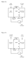
- FIG. 1a shows a schematic representation of one embodiment of the process according to the present invention, in which the condenser surface forms a non-permeable heat conducting separation wall between the distillate stream and the feed stream.
- a feed stream of a liquid mixture is first heated via heat-exchanging contact with the condensing vapor.
- An external heat exchanger is then used for additional heating of said feed stream.
- the thus obtained vaporizing stream is led over a permeable non-porous selective membrane, whereby at least part of the liquid passes through said membrane leaving the other side of said membrane as a vapor, with the remainder of the liquid forming a retentate stream.
- FIG. 1b shows schematic representation of an embodiment of the process according to the present invention, in which the condenser surface forms a non-permeable heat conducting separation wall between the distillate stream and the retentate stream.
- a vaporizing stream of a liquid mixture is led over a permeable non-porous selective membrane, whereby at least part of the liquid passes through said membrane leaving the other side of said membrane as a vapor, with the remainder of the liquid forming a retentate stream.
- Said retentate stream is subsequently cooled using a heat exchanger and is then brought into contact with the non-permeable heat conducting separation wall, functioning as a cooling medium for the condenser surface.
- the difference in vapor pressure between the distillate stream and the vaporizing stream is the main driving force behind the separation in the process according to the present invention.
- Said difference in vapor pressure is preferably larger than 15 kPa, more preferably larger than 25 kPa, most preferably larger than 50 kPa.
- the vapor pressure difference is preferably at least 15 kPa.
- the difference in vapor pressure is preferably at least 20 kPa.
- the value of the vapor pressure is i . a . dependent on the membrane used and the composition of the mixture to be separated.
- a relatively large difference in vapor pressure is applied in the case of a highly selective membrane, preferably larger than 50 kPa, to create a significant flux through the membrane.
- the flux as used herein is defined as the rate with which the distillate is obtained per unit membrane surface area.
- the difference in vapor pressure is preferably smaller than 200 kPa, more preferably smaller than 100 kPa.
- the vapor pressure of a liquid is strongly dependent on the temperature of said liquid.
- the vapor pressure of the vaporizing stream is thus dependent on the temperature of said vaporizing stream and the vapor pressure of the distillate stream is dependent on the temperature of the distillate stream.
- the difference between these temperatures mainly determines the driving force of the separation.
- the main driving force behind the process of the present invention can be controlled by regulating the temperature difference between said vaporizing stream and said cooling stream. Since the temperature in the streams may not be uniform, temperature averages can be measured for each stream.
- the difference in temperature average between the vaporizing stream and the cooling stream is preferably larger than 5 °C, more preferably larger than 10 °C.
- the difference in temperature average between the vaporizing stream and the cooling stream should not be too high, for large temperature differences may result in energy loss, thus making the pervaporation less energy sufficient.
- the difference in temperature average between the vaporizing stream and the cooling stream is therefore preferably smaller than 30 °C, more preferably smaller than 20 °C.
- the distance between the permeable non-porous selective membrane and the condensing surface should preferably be small, to minimize energy loss that occurs when the permeate vapor would be transported over a large distance. However, the distance should not be too small to prevent capillary action between the membrane and the condensing surface.
- the distance between the permeable non-porous selective membrane and the condensing surface is larger than 1 mm, more preferably larger than 2 mm.
- the distance between the permeable non-porous selective membrane and the condensing surface is smaller than 10 mm, preferably smaller than 4 mm.
- the space between the membrane and the condenser surface may be filled with so called spacer materials, consisting of nettings, technical fabrics and the like, made of woven or non woven filaments in various shapes (see Figure 2 ), of polymers like polypropylene (PP), polyethylene (PE), ethylenevinyl acetate (EVA), etc. Suitable shapes include symmetrical squares, rectangles, diamonds, waves, etc.; also, asymmetrical shapes and filaments can be used.
- spacer materials consisting of nettings, technical fabrics and the like, made of woven or non woven filaments in various shapes (see Figure 2 ), of polymers like polypropylene (PP), polyethylene (PE), ethylenevinyl acetate (EVA), etc.
- Suitable shapes include symmetrical squares, rectangles, diamonds, waves, etc.; also, asymmetrical shapes and filaments can be used.
- the spacer works by forcing the liquid up and down while it flows along. This creates turbulence, which helps to keep the concentration and temperature as uniform as possible in the channels. It also prevents the membrane and condenser sheet to touch each other or move further apart.
- a liquid layer may form on the membrane surface on the side of the vaporizing stream. This layer is called the depletion layer. Molecules evaporating from the depletion layer through the membrane will result in cooling of the depletion layer. The thickness of the depletion layer thus has a negative effect on the mass transfer.
- Mass transfer is defined as the transport single components in the evaporated vaporizing stream through the membrane (as opposed to the flux which relates to the total of components) and can be expressed by the amount of distillate obtained (in kg) per unit membrane surface (in m -2 ) over time (e.g. per hour, in h -1 ).
- the heat that is required to partially evaporate the feed is supplied by the bulk solution in the vaporizing stream.
- the total resistance to heat transfer comprises the membrane resistance and the depletion layer formed on the membrane surface.
- the temperature on the membrane surface decreases until an equilibrium is reached where the heat flux from the bulk in the vaporizing stream to the depletion layer equals the heat transported through the membrane to the distillate stream plus the heat required for evaporation of the depletion layer. Decreasing the thickness of depletion layer results in higher temperature on the membrane surface and therefore in higher fluxes of heat and mass.
- Double-layers of said spacer materials are preferred to increase the mass transfer.
- the double-layered spacer forces the distillate stream to flow in a weaving motion, creating a turbulence in the space between the membrane and the condenser surface that increases mixing and therefore increases the amount of heat transported to the depletion layer. This decreases the depletion layer that forms on the membrane surface and subsequently inhibits cooling of the liquid due to evaporation in the layer in touch with the membrane.
- a sweep gas may be applied in the space between the membrane and the condenser surface.
- the presence of the sweep gas results in a lower partial vapor pressure of the distillate stream, which thus increases the driving force of the separation.
- an inert gas is used as a sweep gas.
- sweep gases that can be used in the present invention are nitrogen, helium, air, carbon dioxide or argon.
- the feed is pumped into a feed channel leading to the selective membrane under a certain pressure.
- This pressure is called the hydrostatic pressure.
- Increasing the hydrostatic pressure enables operation at higher temperatures, because the boiling point of a substance increases when the pressure is increased. Operating at higher temperatures may be advantageous, because this increases the flux of the pervaporation process.
- the system can operate at low flux of distillate (i.e. low mass transfer), high flux is desired. In view of heat recovery, it is also of interest to have high flux of distillate. Nevertheless, applying a low hydrostatic pressure is in most cases preferred in view of energy conservation. Furthermore, a high pressure might increase the risk of damaging and/or compaction of the permeable non-porous selective membrane.
- the hydrostatic pressure in the feed channel is 1 to 2 bar.
- the resulting pressure in the system may vary between 0.1 to 0.5 bar.
- Any pump that provides a stable flow and can overcome the system pressure drop can be used to apply the hydrostatic pressure, for example a gear pump or a centrifugal pump.
- the condenser surface area is preferably 0.1 - 2 times the surface area of the permeable non-porous selective membrane. This can for instance be realized by providing condenser tubes within a hollow fiber non-porous selective membrane. Smaller values may result in a decrease of driving force. Larger values are not preferred, because of possible heat loss.
- the feed stream has to be in heat-exchanging contact with the cooling stream.
- the feed stream may for example flow countercurrent, co-current or crosscurrent with respect to the cooling stream.
- Part of the distillate stream may be recycled by leading at least part of the distillate stream back to the feed stream.
- concentration of the compound(s) to be permeated will be increased in the feed stream, thus increasing the driving force and thereby decreasing the loss of product.
- the permeable non-porous selective membrane is chosen from polymeric membranes, ceramic (inorganic) membranes, supported liquid membranes, mixed matrix membranes or combinations of these materials.
- the materials that are used for these membranes can be for example polydimethylsiloxane (PDMS), polyvinyl acetate (PVA), perfluoro polymers or polyoctylmethylsiloxane (POMS) for polymeric membranes, silicate-1 for ceramic membranes, silicone rubber loaded with zeolite particles for mixed matrix membranes trioctylamine (TOA) in porous polypropylene (PP) for supported liquid membranes.
- PDMS polydimethylsiloxane
- PVA polyvinyl acetate
- POMS polyoctylmethylsiloxane
- silicate-1 for ceramic membranes
- TOA
- Permeable non-porous selective membranes are generally composed of three layers: a support layer, an ultra filtration membrane and a top layer.
- the selectivity of the membrane is mainly determined by the top layer.
- said top layer may have a thickness of 0.1-100 ⁇ m, more preferably 0.1-10 ⁇ m, and most preferably 0.1-1 ⁇ m.
- the liquid mixture according to the present invention comprises a hydrophilic first compound and a hydrophobic second compound.
- the process according to the present invention can be used to separate liquid mixtures comprising water and an organic compound.
- organic compounds that may be used are aromatic hydrocarbons, alcohols (e.g. ethanol, butanol, ethylene glycol, glycerol), ketones (e.g. acetone), esters, cyclic ethers, halogenated hydrocarbons, organic acids (e.g. acetic acid), aliphatic amines (e.g. triethylamine), aromatic amines (e.g. pyridine), aprotic solvents (e.g. dimethyl formamide, dimethyl sulfoxide) and mineral acids (e.g. sulfuric acid).
- alcohols e.g. ethanol, butanol, ethylene glycol, glycerol
- ketones e.g. acetone
- esters e.g. acetone
- esters e.g. acetone
- cyclic ethers e.g. halogenated hydrocarbon
- the liquid mixture according to the present invention is obtained from waste streams comprising organic compounds, for example waste streams from chemical industry plants.
- the process according to the present invention is used to purify biofuels comprising for example ethanol, acetone and/or butanol.
- Biofuels can be obtained in fermentation processes from biomass.
- distillation techniques are generally used. Distillation processes can be economically and energetically efficient at large scales due to heat integration and economies of scale. However, distillation is energetically less favorable when the scale of operation is reduced or when the concentration of a compound is below 1 wt.%.
- Fermentation broths for example often comprise low concentrations (about 1 wt.%) of butanol. Above this concentration, butanol becomes toxic to the bacteria that produce it, so it has to be removed from the broth in order to keep the fermentation going.
- This process can be performed using the method according to the present invention.
- Other separation techniques that could be applied are for example gas stripping, extraction, pertraction, vacuum stripping, or adsorption.
- a disadvantage of extraction and pertraction is the risk of broth contamination by toxic solvents, while adsorption techniques cost a lot of energy.
- the advantages of pervaporation over the other techniques are process simplicity, no toxicity and the reduction of further purification costs.
- the process of the present invention further decreases the energy costs of pervaporation, thus making it particular suitable for the purification of biofuels, in particular for lowering of the concentration of butanol from fermentation broths.
- the present invention may further be used for dewatering butanol and ethanol.
- heat required for process of the invention is derived from waste heat of another process, such as from the waste heat of industrial water. This further lowers the required energy for carrying out the process of the invention.
- the invention is directed to an apparatus suitable for use in the method of the invention.
- the apparatus comprises one or more modules comprising a feed channel, a distillate channel and a retentate channel, whereby the segment has a first distribution chamber for feed liquid to be supplied, a second distribution chamber located opposite the first distribution chamber for feed liquid to be discharged, a third distribution chamber for vaporizing stream to be supplied, a fourth distribution chamber opposite the third distribution chamber for the vaporizing stream to be discharged and a fifth distribution chamber located at the bottom of the module to remove the permeate stream, whereby the segment is provided with a first pressure means for pumping the feed stream under pressure into the segment and a second pressure means which is arranged downstream the second distribution chamber for pumping the vaporizing stream under pressure into the retentate channel, the wall between the feed channel and the distillate channel comprising a condenser surface in the form of a non-permeable heat conducting separation wall, and the wall between the retentate channel and the distillate channel comprising a permeable
- a sixth distribution chamber may be located at the top of the module which may be used to distribute a sweep gas, presenting access to the space between the selective non-porous membrane and the heat conducting non-permeable wall.
- the apparatus according to the invention may comprise more than one module, operated in parallel.
- the feed stream is split up into multiple feed streams and divided over the modules.
- the apparatus comprises one or more modules comprising eight units (see Figure 3 ), being four frames, two condenser sheets and two membrane envelopes (comprising a non-porous selective membrane).
- Each unit has a number of openings, so that when the frames are connected, channels are formed through which the feed stream (cold feed), vaporizing stream (hot feed), distillate stream (condensate), retentate stream (retentate) and, optionally, a sweep gas can be led (see Figure 3 ).
- a first frames is connected on both sides with the two membrane envelopes, thus providing the retentate channel.
- Each membrane envelope is on the other side (i.e. the side not connected with the first frame) connected with a frame and a condenser sheet, thus providing two distillate channels.
- One of the two condenser sheets is further connected with the last frame.
- the first experiment was conducted using a high mass transfer (1). This means the temperature difference is high resulting in a high driving force.
- the second experiment is using a low mass transfer (2), which means the temperature difference is lower, resulting in a lower driving force.
- the temperature difference was smaller in the second experiment, but the water content was lower in experiment two. Both these factors decrease the driving force, which results in a lower separation factor, a lower flux and thus a lower heat recovery.
- the separation factor is defined as the ratio of water and butanol molecules that have passed through the selective membrane.
- a separation factor of 60 means that the selective membrane will have let through 60 times as much water molecules as butanol molecules.
Landscapes
- Chemical & Material Sciences (AREA)
- Chemical Kinetics & Catalysis (AREA)
- Engineering & Computer Science (AREA)
- Water Supply & Treatment (AREA)
- Separation Using Semi-Permeable Membranes (AREA)
Abstract
The invention is directed to a process for separating liquid mixtures and an apparatus for separating liquid mixtures by pervaporation. The process of the invention comprises:
- passing a stream of the liquid mixture over a permeable non-porous selective membrane, said membrane being selective for at least one of said first and second compounds, whereby at least part of the stream passes through said membrane leaving the other side of said membrane as a vapor, with the remainder forming a retentate stream, and
- condensing said vapor on a condenser surface having a lower temperature than the vaporizing stream to give a distillate stream, said condenser surface forming a non-permeable heat conducting separation wall between said distillate stream and a cooling stream which cooling stream is
a) said feed stream or
b) said retentate stream,
so that heat can be transferred between the vapor and the cooling stream, wherein the distance between said membrane and said condenser surface is smaller than 10 mm, and
wherein the vapor pressure of said distillate stream is lower than the vapor pressure of the compounds in the vaporizing stream for which the permeable non-porous selective membrane is selective, resulting in sufficient driving force for the separation to occur.
- passing a stream of the liquid mixture over a permeable non-porous selective membrane, said membrane being selective for at least one of said first and second compounds, whereby at least part of the stream passes through said membrane leaving the other side of said membrane as a vapor, with the remainder forming a retentate stream, and
- condensing said vapor on a condenser surface having a lower temperature than the vaporizing stream to give a distillate stream, said condenser surface forming a non-permeable heat conducting separation wall between said distillate stream and a cooling stream which cooling stream is
a) said feed stream or
b) said retentate stream,
so that heat can be transferred between the vapor and the cooling stream, wherein the distance between said membrane and said condenser surface is smaller than 10 mm, and
wherein the vapor pressure of said distillate stream is lower than the vapor pressure of the compounds in the vaporizing stream for which the permeable non-porous selective membrane is selective, resulting in sufficient driving force for the separation to occur.
Description
- The invention is directed to a process for separating liquid mixtures, an apparatus for separating liquid mixtures.
- It is known from the art that liquid mixtures can be separated by pervaporation. Pervaporation is a separation process in which a membrane in contact with a feed stream of a liquid mixture selectively absorbs one or more of the species from the feed stream. The sorbed species permeate across the membrane under the influence of a vapour pressure gradient that is produced by removing the permeate from the product side of the membrane using a vacuum or sweep gas. Industrially, vacuum is economically produced by condensing the permeate stream. This spontaneously generates a partial vacuum that drives the process. In all cases, permeate vapor is eventually condensed and the resulting distillate stream recovered as a liquid. An advantage of pervaporation over distillation is that, because of the selectivity of the membrane, pervaporation can separate azeotropic mixtures beyond the azeotropic ratio.
-
WO-A-2008/054 207 describes a method for the purification of a liquid by direct contact membrane distillation, in particular for the production of desalinated water from seawater or brackish water. The method comprises passing a heated vaporizing stream of a liquid over a porous membrane. The porous membrane is hydrophobic and the pores are filled with air. Thus, liquid water is unable to pass through the hydrophobic membrane, while water vapor and other gas molecules can pass through the membrane. Vapor of the liquid flows through the membrane and is condensed on the other side at a condenser surface, which surface forms a non-porous separation between a feed stream of the liquid to be purified and the (condensed) vapor. The method described inWO-A-2008/054 207 is energy efficient in that both the costs and the energy consumption of the membrane distillation system are low. - Disadvantage of this method is that this process cannot be used for separating liquid mixtures comprising hydrophobic liquids and hydrophilic liquids. When a hydrophobic/hydrophilic mixture would be applied according to the method described in
WO-A-2008/054207 , pore wetting would occur which may result in the membrane becoming impermeable or leakage. Liquid mixtures may in principle be separated using the method described inWO-A-2008/054207 , but only with limited efficiency because the membrane is not selective. Passing the azeotrope of a mixture is impossible using this method. - Object of the invention is to at least partly overcome the above-mentioned disadvantages and to provide a process for separating liquid mixtures, which process requires a minimum amount of energy to work.
- The inventors found that this object can be met by making use of a pervaporation process, in which the permeate vapor is condensed on a non-permeable heat-conducting condenser surface, which surface is in heat-exchanging contact with either
- a) the feed stream, in case the feed stream has a sufficiently low temperature to serve as a suitable cooling medium for the condensation of the permeate vapor, or
- b) the retentate stream, in case the feed stream has such a high temperature that would make it unsuitable as a cooling medium for the condensation of the permeate vapor.
- The invention thus optimizes the internal recovery of heat, resulting in a minimum amount of heat loss. Furthermore, the temperature difference between the cooled distillate stream and the vaporizing stream results in a difference in vapor pressure, which contributes to the driving force behind the separation, reducing the energy consumption of the process. Thus, the present invention provides for a pervaporation process which does not need a vacuum or a sweep gas for separation to occur.
- In a first aspect, the present invention is directed to a process for separating a feed stream of a liquid mixture comprising at least a first compound and a second compound, comprising:
- passing a vaporizing stream of the liquid mixture over a permeable non-porous selective membrane, said membrane being selective for at least one of said first and second compound, whereby at least part of the vaporizing stream passes through said membrane leaving the other side of said membrane as a vapor, with the remainder of the vaporizing stream forming a retentate stream, and
- condensing said vapor on a condenser surface having a lower temperature than the vaporizing stream to give a distillate stream, said condenser surface forming a non-permeable heat conducting separation wall between said distillate stream and a cooling stream, which cooling stream is either
- a) said feed stream, in case the feed stream has a sufficiently low temperature to serve as a suitable cooling medium for the condensation of the permeate vapor, or
- b) said retentate stream, in case the feed stream has such a high temperature that would make it unsuitable as a cooling medium for the condensation of the permeate vapor,
- A heat exchanger may be used in the present invention to increase the temperature difference between the vaporizing stream and the cooling stream. Said heat exchanger is preferably placed between the vaporizing stream and the cooling stream. The heat exchanger can either function as a heating source or as a cooling source, whichever function is needed to increase said temperature difference.
-
Figure 1a shows a schematic representation of one embodiment of the process according to the present invention, in which the condenser surface forms a non-permeable heat conducting separation wall between the distillate stream and the feed stream. A feed stream of a liquid mixture is first heated via heat-exchanging contact with the condensing vapor. An external heat exchanger is then used for additional heating of said feed stream. The thus obtained vaporizing stream is led over a permeable non-porous selective membrane, whereby at least part of the liquid passes through said membrane leaving the other side of said membrane as a vapor, with the remainder of the liquid forming a retentate stream. -
Figure 1b shows schematic representation of an embodiment of the process according to the present invention, in which the condenser surface forms a non-permeable heat conducting separation wall between the distillate stream and the retentate stream. A vaporizing stream of a liquid mixture is led over a permeable non-porous selective membrane, whereby at least part of the liquid passes through said membrane leaving the other side of said membrane as a vapor, with the remainder of the liquid forming a retentate stream. Said retentate stream is subsequently cooled using a heat exchanger and is then brought into contact with the non-permeable heat conducting separation wall, functioning as a cooling medium for the condenser surface. - The difference in vapor pressure between the distillate stream and the vaporizing stream is the main driving force behind the separation in the process according to the present invention. Said difference in vapor pressure is preferably larger than 15 kPa, more preferably larger than 25 kPa, most preferably larger than 50 kPa. For example, when ethanol is removed from water using the method according to the present invention, the vapor pressure difference is preferably at least 15 kPa. When removing water from an organic stream, the difference in vapor pressure is preferably at least 20 kPa. The value of the vapor pressure is i.a. dependent on the membrane used and the composition of the mixture to be separated. Suitably a relatively large difference in vapor pressure is applied in the case of a highly selective membrane, preferably larger than 50 kPa, to create a significant flux through the membrane. The flux as used herein is defined as the rate with which the distillate is obtained per unit membrane surface area. Usually, the difference in vapor pressure is preferably smaller than 200 kPa, more preferably smaller than 100 kPa.
- The vapor pressure of a liquid is strongly dependent on the temperature of said liquid. In the present invention, the vapor pressure of the vaporizing stream is thus dependent on the temperature of said vaporizing stream and the vapor pressure of the distillate stream is dependent on the temperature of the distillate stream. The difference between these temperatures mainly determines the driving force of the separation.
- Since the temperature, and thus the vapor pressure of the distillate stream is mainly determined by the temperature of the cooling stream, the main driving force behind the process of the present invention can be controlled by regulating the temperature difference between said vaporizing stream and said cooling stream. Since the temperature in the streams may not be uniform, temperature averages can be measured for each stream. The difference in temperature average between the vaporizing stream and the cooling stream is preferably larger than 5 °C, more preferably larger than 10 °C.
- Furthermore, the difference in temperature average between the vaporizing stream and the cooling stream should not be too high, for large temperature differences may result in energy loss, thus making the pervaporation less energy sufficient. The difference in temperature average between the vaporizing stream and the cooling stream is therefore preferably smaller than 30 °C, more preferably smaller than 20 °C.
- The distance between the permeable non-porous selective membrane and the condensing surface should preferably be small, to minimize energy loss that occurs when the permeate vapor would be transported over a large distance. However, the distance should not be too small to prevent capillary action between the membrane and the condensing surface. Preferably, the distance between the permeable non-porous selective membrane and the condensing surface is larger than 1 mm, more preferably larger than 2 mm. Furthermore, the distance between the permeable non-porous selective membrane and the condensing surface is smaller than 10 mm, preferably smaller than 4 mm.
- The space between the membrane and the condenser surface may be filled with so called spacer materials, consisting of nettings, technical fabrics and the like, made of woven or non woven filaments in various shapes (see
Figure 2 ), of polymers like polypropylene (PP), polyethylene (PE), ethylenevinyl acetate (EVA), etc. Suitable shapes include symmetrical squares, rectangles, diamonds, waves, etc.; also, asymmetrical shapes and filaments can be used. - The spacer works by forcing the liquid up and down while it flows along. This creates turbulence, which helps to keep the concentration and temperature as uniform as possible in the channels. It also prevents the membrane and condenser sheet to touch each other or move further apart.
- When using a non-porous membrane according to the method of the present invention, a liquid layer may form on the membrane surface on the side of the vaporizing stream. This layer is called the depletion layer. Molecules evaporating from the depletion layer through the membrane will result in cooling of the depletion layer. The thickness of the depletion layer thus has a negative effect on the mass transfer. Mass transfer is defined as the transport single components in the evaporated vaporizing stream through the membrane (as opposed to the flux which relates to the total of components) and can be expressed by the amount of distillate obtained (in kg) per unit membrane surface (in m-2) over time (e.g. per hour, in h-1).
- The heat that is required to partially evaporate the feed is supplied by the bulk solution in the vaporizing stream. The total resistance to heat transfer comprises the membrane resistance and the depletion layer formed on the membrane surface. The temperature on the membrane surface decreases until an equilibrium is reached where the heat flux from the bulk in the vaporizing stream to the depletion layer equals the heat transported through the membrane to the distillate stream plus the heat required for evaporation of the depletion layer. Decreasing the thickness of depletion layer results in higher temperature on the membrane surface and therefore in higher fluxes of heat and mass.
- Double-layers of said spacer materials are preferred to increase the mass transfer. The double-layered spacer forces the distillate stream to flow in a weaving motion, creating a turbulence in the space between the membrane and the condenser surface that increases mixing and therefore increases the amount of heat transported to the depletion layer. This decreases the depletion layer that forms on the membrane surface and subsequently inhibits cooling of the liquid due to evaporation in the layer in touch with the membrane.
- A sweep gas may be applied in the space between the membrane and the condenser surface. The presence of the sweep gas results in a lower partial vapor pressure of the distillate stream, which thus increases the driving force of the separation. Preferably, an inert gas is used as a sweep gas. Examples of sweep gases that can be used in the present invention are nitrogen, helium, air, carbon dioxide or argon.
- Typically the feed is pumped into a feed channel leading to the selective membrane under a certain pressure. This pressure is called the hydrostatic pressure. Increasing the hydrostatic pressure enables operation at higher temperatures, because the boiling point of a substance increases when the pressure is increased. Operating at higher temperatures may be advantageous, because this increases the flux of the pervaporation process. Although the system can operate at low flux of distillate (i.e. low mass transfer), high flux is desired. In view of heat recovery, it is also of interest to have high flux of distillate. Nevertheless, applying a low hydrostatic pressure is in most cases preferred in view of energy conservation. Furthermore, a high pressure might increase the risk of damaging and/or compaction of the permeable non-porous selective membrane. Preferably, the hydrostatic pressure in the feed channel is 1 to 2 bar. The resulting pressure in the system may vary between 0.1 to 0.5 bar. Any pump that provides a stable flow and can overcome the system pressure drop can be used to apply the hydrostatic pressure, for example a gear pump or a centrifugal pump.
- The condenser surface area is preferably 0.1 - 2 times the surface area of the permeable non-porous selective membrane. This can for instance be realized by providing condenser tubes within a hollow fiber non-porous selective membrane. Smaller values may result in a decrease of driving force. Larger values are not preferred, because of possible heat loss.
- The feed stream has to be in heat-exchanging contact with the cooling stream. For this purpose, the feed stream may for example flow countercurrent, co-current or crosscurrent with respect to the cooling stream.
- Part of the distillate stream may be recycled by leading at least part of the distillate stream back to the feed stream. In this way, the concentration of the compound(s) to be permeated will be increased in the feed stream, thus increasing the driving force and thereby decreasing the loss of product.
- In an embodiment, the permeable non-porous selective membrane is chosen from polymeric membranes, ceramic (inorganic) membranes, supported liquid membranes, mixed matrix membranes or combinations of these materials. The materials that are used for these membranes can be for example polydimethylsiloxane (PDMS), polyvinyl acetate (PVA), perfluoro polymers or polyoctylmethylsiloxane (POMS) for polymeric membranes, silicate-1 for ceramic membranes, silicone rubber loaded with zeolite particles for mixed matrix membranes trioctylamine (TOA) in porous polypropylene (PP) for supported liquid membranes.
- Permeable non-porous selective membranes are generally composed of three layers: a support layer, an ultra filtration membrane and a top layer. The selectivity of the membrane is mainly determined by the top layer. Regarding the process according to the present invention, said top layer may have a thickness of 0.1-100 µm, more preferably 0.1-10 µm, and most preferably 0.1-1 µm.
- In a preferred embodiment, the liquid mixture according to the present invention comprises a hydrophilic first compound and a hydrophobic second compound.
- In a preferred embodiment, the process according to the present invention can be used to separate liquid mixtures comprising water and an organic compound. Examples of organic compounds that may be used are aromatic hydrocarbons, alcohols (e.g. ethanol, butanol, ethylene glycol, glycerol), ketones (e.g. acetone), esters, cyclic ethers, halogenated hydrocarbons, organic acids (e.g. acetic acid), aliphatic amines (e.g. triethylamine), aromatic amines (e.g. pyridine), aprotic solvents (e.g. dimethyl formamide, dimethyl sulfoxide) and mineral acids (e.g. sulfuric acid).
- In one embodiment, the liquid mixture according to the present invention is obtained from waste streams comprising organic compounds, for example waste streams from chemical industry plants.
- In a preferred embodiment, the process according to the present invention is used to purify biofuels comprising for example ethanol, acetone and/or butanol. Biofuels can be obtained in fermentation processes from biomass. To recover biofuels from the liquid fermentation mixture, distillation techniques are generally used. Distillation processes can be economically and energetically efficient at large scales due to heat integration and economies of scale. However, distillation is energetically less favorable when the scale of operation is reduced or when the concentration of a compound is below 1 wt.%.
- Fermentation broths for example often comprise low concentrations (about 1 wt.%) of butanol. Above this concentration, butanol becomes toxic to the bacteria that produce it, so it has to be removed from the broth in order to keep the fermentation going. This process can be performed using the method according to the present invention. Other separation techniques that could be applied are for example gas stripping, extraction, pertraction, vacuum stripping, or adsorption. A disadvantage of extraction and pertraction is the risk of broth contamination by toxic solvents, while adsorption techniques cost a lot of energy. The advantages of pervaporation over the other techniques are process simplicity, no toxicity and the reduction of further purification costs. The process of the present invention further decreases the energy costs of pervaporation, thus making it particular suitable for the purification of biofuels, in particular for lowering of the concentration of butanol from fermentation broths.
- The present invention may further be used for dewatering butanol and ethanol.
- In an advantageous embodiment, heat required for process of the invention is derived from waste heat of another process, such as from the waste heat of industrial water. This further lowers the required energy for carrying out the process of the invention.
- In a further aspect the invention is directed to an apparatus suitable for use in the method of the invention. The apparatus comprises one or more modules comprising a feed channel, a distillate channel and a retentate channel, whereby the segment has a first distribution chamber for feed liquid to be supplied, a second distribution chamber located opposite the first distribution chamber for feed liquid to be discharged, a third distribution chamber for vaporizing stream to be supplied, a fourth distribution chamber opposite the third distribution chamber for the vaporizing stream to be discharged and a fifth distribution chamber located at the bottom of the module to remove the permeate stream, whereby the segment is provided with a first pressure means for pumping the feed stream under pressure into the segment and a second pressure means which is arranged downstream the second distribution chamber for pumping the vaporizing stream under pressure into the retentate channel, the wall between the feed channel and the distillate channel comprising a condenser surface in the form of a non-permeable heat conducting separation wall, and the wall between the retentate channel and the distillate channel comprising a permeable non-porous selective membrane.
- Optionally, a sixth distribution chamber may be located at the top of the module which may be used to distribute a sweep gas, presenting access to the space between the selective non-porous membrane and the heat conducting non-permeable wall.
- The apparatus according to the invention may comprise more than one module, operated in parallel. The feed stream is split up into multiple feed streams and divided over the modules.
- In a preferred embodiment, the apparatus according to the invention comprises one or more modules comprising eight units (see
Figure 3 ), being four frames, two condenser sheets and two membrane envelopes (comprising a non-porous selective membrane). Each unit has a number of openings, so that when the frames are connected, channels are formed through which the feed stream (cold feed), vaporizing stream (hot feed), distillate stream (condensate), retentate stream (retentate) and, optionally, a sweep gas can be led (seeFigure 3 ). A first frames is connected on both sides with the two membrane envelopes, thus providing the retentate channel. Each membrane envelope is on the other side (i.e. the side not connected with the first frame) connected with a frame and a condenser sheet, thus providing two distillate channels. One of the two condenser sheets is further connected with the last frame. - The present invention will be further illustrated by the following example.
- Two experiments were carried with a liquid mixture of butanol and water. The membrane used was selective for water (i.e. the membrane lets water vapor through), but not for butanol.
- The first experiment was conducted using a high mass transfer (1). This means the temperature difference is high resulting in a high driving force. The second experiment is using a low mass transfer (2), which means the temperature difference is lower, resulting in a lower driving force. The temperature difference was smaller in the second experiment, but the water content was lower in experiment two. Both these factors decrease the driving force, which results in a lower separation factor, a lower flux and thus a lower heat recovery.
- In both cases a pervaporate is obtained that contains less than 7 % in volume of butanol.
- The table below shows a summary of the results. Herein, the separation factor is defined as the ratio of water and butanol molecules that have passed through the selective membrane. A separation factor of 60 means that the selective membrane will have let through 60 times as much water molecules as butanol molecules.
Table 1 Results summary with butanol dewatering 1 2 Energy efficiency 19 % 14 % Flux [Kg/m2/h] 0.555 0.24 ΔT[°C] 60 44 Separation Factor [-] 60 40 Water conc. [vol%] 31 % 25 %
Claims (15)
- Process for separating a feed stream of a liquid mixture comprising at least a first compound and a second compound, comprising:- passing a vaporizing stream of the liquid mixture over a permeable non-porous selective membrane, said membrane being selective for at least one of said first and second compounds, whereby at least part of the vaporizing stream passes through said membrane leaving the other side of said membrane as a vapor, with the remainder of the vaporizing stream forming a retentate stream, and- condensing said vapor on a condenser surface having a lower temperature than the vaporizing stream to give a distillate stream, said condenser surface forming a non-permeable heat conducting separation wall between said distillate stream and a cooling stream which cooling stream iswherein the vapor pressure of said distillate stream is lower than the vapor pressure of the compounds in the vaporizing stream for which the permeable non-porous selective membrane is selective, resulting in sufficient driving force for the separation to occur.a) said feed stream, in case the feed stream has a sufficiently low temperature to serve as a suitable cooling medium for the condensation of the permeate vapor, orb) said retentate stream, in case the feed stream has such a high temperature that would make it unsuitable as a cooling medium for the condensation of the permeate vapor,so that heat can be transferred between the vapor and the cooling stream, wherein the distance between said membrane and said condenser surface is smaller than 10 mm, and
- Process according to claim 1, wherein the distance between the permeable non-porous selective membrane and the condenser surface is 1-10 mm, more preferably 2-4 mm.
- Process according to any one of the previous claims, wherein a spacer is present between the membrane and the condenser surface.
- Process according to any one of the previous claims, wherein the permeable non-porous selective membrane is chosen from the group consisting of polymeric membranes, ceramic membranes, supported liquid membranes, and mixed matrix membranes.
- Process according to any one of the previous claims, wherein the condenser surface is 0.1 - 2 times the surface area of the permeable non-porous selective membrane.
- Process according to claim 5, wherein said non-porous selective membrane is a hollow-fiber membrane, and wherein said condenser surface is the surface of condenser tubes within said hollow-fiber membrane.
- Process according to any one of the previous claims, wherein said feed stream flows in countercurrent, co-current or crosscurrent to said retentate stream.
- Process according to any one of the previous claims, wherein the distillate stream is led back to the feed stream.
- Process according to any one of the previous claims, wherein the difference in vapor pressure between said distillate stream and said vaporizing retentate stream is 1-200 kPa, more preferably 15-100 kPa.
- Process according to any one of the previous claims, wherein the permeable non-porous selective membrane comprises a selective top layer having a thickness of 0.1-100 µm, more preferably 0.1-10 µm, and most preferably 0.1-1 µm.
- Process according to any one of the previous claims, wherein said first compound is hydrophilic and said second compound is hydrophobic.
- Process according to any one of the previous claims, wherein said liquid mixture comprises water and an organic compound.
- Process according claim 12, wherein said organic compound is selected from the group consisting of ethanol, butanol, ethylene glycol, glycerol and acetone.
- Process according to any one of the previous claims, wherein the liquid mixture is a fermentation broth, preferably comprising ethanol, acetone and/or butanol.
- Apparatus suitable for use in the process according to any one of the previous claims, which apparatus comprises one or more modules comprising a feed channel, a distillate channel and a retentate channel, whereby the segment has a first distribution chamber for feed liquid to be supplied, a second distribution chamber located opposite the first distribution chamber for feed liquid to be discharged, a third distribution chamber for vaporizing stream to be supplied, a fourth distribution chamber opposite the third distribution chamber for the vaporizing stream to be discharged and a fifth distribution chamber located at the bottom of the module to remove the permeate stream, whereby the segment is provided with a first pressure means for pumping the feed stream under pressure into the segment and a second pressure means which is arranged downstream the second distribution chamber for pumping the vaporizing stream under pressure into the retentate channel, the wall between the feed channel and the distillate channel comprising a condenser surface in the form of a non-permeable heat conducting separation wall, and the wall between the retentate channel and the distillate channel comprising a permeable non-porous selective membrane.
Priority Applications (7)
| Application Number | Priority Date | Filing Date | Title |
|---|---|---|---|
| EP08162585A EP2156880A1 (en) | 2008-08-19 | 2008-08-19 | Process for separating liquid mixtures |
| CA2733039A CA2733039C (en) | 2008-08-19 | 2009-08-19 | Process for separating liquid mixtures by pervaporation |
| BRPI0917312A BRPI0917312A2 (en) | 2008-08-19 | 2009-08-19 | process for separating a feed stream from a liquid, and apparatus suitable for use in |
| EP09808441.1A EP2331241B1 (en) | 2008-08-19 | 2009-08-19 | Pervaporation process for separating liquid mixtures |
| US13/056,760 US9283522B2 (en) | 2008-08-19 | 2009-08-19 | Process for separating liquid mixtures |
| JP2011523758A JP2012500114A (en) | 2008-08-19 | 2009-08-19 | Separation method of liquid mixture |
| PCT/NL2009/050501 WO2010021545A1 (en) | 2008-08-19 | 2009-08-19 | Process for separating liquid mixtures |
Applications Claiming Priority (1)
| Application Number | Priority Date | Filing Date | Title |
|---|---|---|---|
| EP08162585A EP2156880A1 (en) | 2008-08-19 | 2008-08-19 | Process for separating liquid mixtures |
Publications (1)
| Publication Number | Publication Date |
|---|---|
| EP2156880A1 true EP2156880A1 (en) | 2010-02-24 |
Family
ID=39970875
Family Applications (2)
| Application Number | Title | Priority Date | Filing Date |
|---|---|---|---|
| EP08162585A Withdrawn EP2156880A1 (en) | 2008-08-19 | 2008-08-19 | Process for separating liquid mixtures |
| EP09808441.1A Not-in-force EP2331241B1 (en) | 2008-08-19 | 2009-08-19 | Pervaporation process for separating liquid mixtures |
Family Applications After (1)
| Application Number | Title | Priority Date | Filing Date |
|---|---|---|---|
| EP09808441.1A Not-in-force EP2331241B1 (en) | 2008-08-19 | 2009-08-19 | Pervaporation process for separating liquid mixtures |
Country Status (6)
| Country | Link |
|---|---|
| US (1) | US9283522B2 (en) |
| EP (2) | EP2156880A1 (en) |
| JP (1) | JP2012500114A (en) |
| BR (1) | BRPI0917312A2 (en) |
| CA (1) | CA2733039C (en) |
| WO (1) | WO2010021545A1 (en) |
Cited By (8)
| Publication number | Priority date | Publication date | Assignee | Title |
|---|---|---|---|---|
| CN104364203A (en) * | 2012-05-30 | 2015-02-18 | 旭化成化学株式会社 | Method and device for obtaining purified water |
| WO2019233606A1 (en) * | 2018-06-08 | 2019-12-12 | Evcon Gmbh | Modular flow system with enhanced vapor and/or liquid channel configuration |
| US11712662B2 (en) | 2018-06-08 | 2023-08-01 | Evcon Gmbh | Modular flow system with internal strut members |
| US11833473B2 (en) | 2018-06-08 | 2023-12-05 | Evcon Gmbh | Modular flow system with asymmetric or discontinuous liquid passage |
| US11857928B2 (en) | 2018-06-08 | 2024-01-02 | Evcon Gmbh | Multistage membrane distillation apparatus |
| EP4417282A1 (en) * | 2023-02-20 | 2024-08-21 | EvCon GmbH | Distillation system |
| US12134075B2 (en) | 2018-06-08 | 2024-11-05 | Evcon Gmbh | Membrane distillation apparatus for producing water |
| EP4529977A1 (en) * | 2023-09-28 | 2025-04-02 | EvCon GmbH | Distillation system |
Families Citing this family (14)
| Publication number | Priority date | Publication date | Assignee | Title |
|---|---|---|---|---|
| JP5897458B2 (en) * | 2010-03-26 | 2016-03-30 | 日本碍子株式会社 | Pervaporation separation method |
| EP2680955B1 (en) | 2011-03-03 | 2019-10-23 | Victoria University | A heat exchange system |
| GB2504503A (en) * | 2012-07-31 | 2014-02-05 | Ibm | Desalination system |
| JP6229596B2 (en) * | 2014-06-06 | 2017-11-15 | 栗田工業株式会社 | Suspension concentration system and concentration method |
| US9513042B2 (en) * | 2014-09-07 | 2016-12-06 | Michael Gurin | Heat exchangerless heat transfer of immiscible fluids |
| WO2017062812A1 (en) * | 2015-10-07 | 2017-04-13 | Dais Analytic Corporation | Evaporative chilling systems and methods using a selective transfer membrane |
| CA3046979C (en) | 2017-03-20 | 2020-03-24 | Lanzatech, Inc. | A process and system for product recovery and cell recycle |
| WO2019046397A1 (en) * | 2017-08-29 | 2019-03-07 | Dais Analytic Corporation | Membrane evaporation enhanced vapor condenser |
| EP3517204A1 (en) * | 2018-01-26 | 2019-07-31 | Nederlandse Organisatie voor toegepast- natuurwetenschappelijk onderzoek TNO | Reactor and process for the hydrogenation of carbon dioxide |
| US11091415B2 (en) | 2019-02-08 | 2021-08-17 | Lanzatech, Inc. | Process for recovering close boiling products |
| US11439948B2 (en) * | 2019-12-09 | 2022-09-13 | Mahle International Gmbh | Membrane module for mitigating evaporative fuel emissions of automobiles |
| CN111715076B (en) * | 2020-06-11 | 2021-09-28 | 江南大学 | Air energy vacuum membrane distillation device and distillation method |
| US20220176321A1 (en) * | 2020-12-09 | 2022-06-09 | New Jersey Institute Of Technology | System and Process for Hybrid Membrane Distillation-Pervaporation |
| JPWO2024004742A1 (en) * | 2022-06-28 | 2024-01-04 |
Citations (8)
| Publication number | Priority date | Publication date | Assignee | Title |
|---|---|---|---|---|
| EP0039197A1 (en) * | 1980-04-25 | 1981-11-04 | W.L. GORE & ASSOCIATES, INC. | Distillation apparatus |
| US4391676A (en) * | 1980-03-24 | 1983-07-05 | Finn Torberger | Arrangement for passing a first liquid close to, but without mixing it with a second liquid, for example an arrangement for sea water desalination |
| GB2151155A (en) * | 1983-12-13 | 1985-07-17 | Nitto Electric Ind Co | Thermopervaporation apparatus |
| US4746437A (en) * | 1984-02-27 | 1988-05-24 | Hitachi, Ltd. | Method and apparatus for concentration aqueous solution and method and apparatus for recovering temperature |
| JPS63137705A (en) * | 1986-12-01 | 1988-06-09 | Hitachi Ltd | membrane distillation equipment |
| EP0894524A2 (en) * | 1994-06-22 | 1999-02-03 | Fls Miljo A/S | Mass transfer method |
| EP1762295A1 (en) * | 2005-09-12 | 2007-03-14 | Nederlandse Organisatie voor Toegepast-Natuuurwetenschappelijk Onderzoek TNO | Pervaporation process and apparatus for carrying out same |
| WO2008054207A1 (en) | 2006-10-31 | 2008-05-08 | Nederlandse Organisatie Voor Toegepast-Natuurwetenschappelijk Onderzoek Tno | Membrane distillation method for the purification of a liquid |
Family Cites Families (12)
| Publication number | Priority date | Publication date | Assignee | Title |
|---|---|---|---|---|
| JPS57113801A (en) * | 1980-04-25 | 1982-07-15 | Gore & Ass | Distillation method and its device |
| SE447728B (en) * | 1985-06-17 | 1986-12-08 | Svenska Utvecklings Ab | DISTILLATION DEVICE FOR THE DISTILLATION OF LIQUID CONTAINING A MEMBRANE |
| US4944882A (en) * | 1989-04-21 | 1990-07-31 | Bend Research, Inc. | Hybrid membrane separation systems |
| US5464540A (en) * | 1993-12-09 | 1995-11-07 | Bend Research, Inc. | Pervaporation by countercurrent condensable sweep |
| JP4491153B2 (en) * | 1999-05-27 | 2010-06-30 | ネーデルランドセ・オルガニザテイエ・フール・テゲパスト−ナトウールベテンシヤツペリーク・オンデルツエク・テイエヌオー | A method for purifying a liquid by membrane distillation, in particular for the purpose of producing demineralized water from seawater, blackish water or process water |
| CA2351272C (en) * | 2001-06-22 | 2009-09-15 | Petro Sep International Ltd. | Membrane-assisted fluid separation apparatus and method |
| US6899743B2 (en) * | 2002-06-12 | 2005-05-31 | Membrane Technology And Research, Inc. | Separation of organic mixtures using gas separation or pervaporation and dephlegmation |
| US8167143B2 (en) * | 2004-07-28 | 2012-05-01 | New Jersey Institute Of Technology | Desalination devices and systems using porous hydrophobic hollow fibers and hydrophobic porous coatings |
| US7732173B2 (en) * | 2005-08-03 | 2010-06-08 | Membrane Technology And Research, Inc. | Ethanol recovery process |
| DE112007002581T5 (en) * | 2006-10-27 | 2009-12-03 | Cms Technology Holdings Inc., Newport | Removing water and methanol from fluids |
| US20080131948A1 (en) * | 2006-12-01 | 2008-06-05 | Leo Ernest Manzer | Process for making isooctenes from dry 2-butanol |
| US8002874B2 (en) * | 2007-03-06 | 2011-08-23 | Membrane Technology And Research, Inc. | Liquid-phase and vapor-phase dehydration of organic/water solutions |
-
2008
- 2008-08-19 EP EP08162585A patent/EP2156880A1/en not_active Withdrawn
-
2009
- 2009-08-19 WO PCT/NL2009/050501 patent/WO2010021545A1/en not_active Ceased
- 2009-08-19 BR BRPI0917312A patent/BRPI0917312A2/en active Search and Examination
- 2009-08-19 CA CA2733039A patent/CA2733039C/en not_active Expired - Fee Related
- 2009-08-19 US US13/056,760 patent/US9283522B2/en not_active Expired - Fee Related
- 2009-08-19 JP JP2011523758A patent/JP2012500114A/en active Pending
- 2009-08-19 EP EP09808441.1A patent/EP2331241B1/en not_active Not-in-force
Patent Citations (8)
| Publication number | Priority date | Publication date | Assignee | Title |
|---|---|---|---|---|
| US4391676A (en) * | 1980-03-24 | 1983-07-05 | Finn Torberger | Arrangement for passing a first liquid close to, but without mixing it with a second liquid, for example an arrangement for sea water desalination |
| EP0039197A1 (en) * | 1980-04-25 | 1981-11-04 | W.L. GORE & ASSOCIATES, INC. | Distillation apparatus |
| GB2151155A (en) * | 1983-12-13 | 1985-07-17 | Nitto Electric Ind Co | Thermopervaporation apparatus |
| US4746437A (en) * | 1984-02-27 | 1988-05-24 | Hitachi, Ltd. | Method and apparatus for concentration aqueous solution and method and apparatus for recovering temperature |
| JPS63137705A (en) * | 1986-12-01 | 1988-06-09 | Hitachi Ltd | membrane distillation equipment |
| EP0894524A2 (en) * | 1994-06-22 | 1999-02-03 | Fls Miljo A/S | Mass transfer method |
| EP1762295A1 (en) * | 2005-09-12 | 2007-03-14 | Nederlandse Organisatie voor Toegepast-Natuuurwetenschappelijk Onderzoek TNO | Pervaporation process and apparatus for carrying out same |
| WO2008054207A1 (en) | 2006-10-31 | 2008-05-08 | Nederlandse Organisatie Voor Toegepast-Natuurwetenschappelijk Onderzoek Tno | Membrane distillation method for the purification of a liquid |
Cited By (12)
| Publication number | Priority date | Publication date | Assignee | Title |
|---|---|---|---|---|
| CN104364203A (en) * | 2012-05-30 | 2015-02-18 | 旭化成化学株式会社 | Method and device for obtaining purified water |
| EP2857358A4 (en) * | 2012-05-30 | 2015-08-26 | Asahi Kasei Chemicals Corp | METHOD AND DEVICE FOR OBTAINING PURIFIED WATER |
| WO2019233606A1 (en) * | 2018-06-08 | 2019-12-12 | Evcon Gmbh | Modular flow system with enhanced vapor and/or liquid channel configuration |
| CN112601602A (en) * | 2018-06-08 | 2021-04-02 | 伊弗科恩有限责任公司 | Modular flow system with enhanced vapor and/or liquid passage configuration |
| US11400417B2 (en) | 2018-06-08 | 2022-08-02 | Evcon Gmbh | Modular flow system with enhanced vapor and/or liquid channel configuration |
| CN112601602B (en) * | 2018-06-08 | 2022-12-13 | 伊弗科恩有限责任公司 | Modular flow system with enhanced vapor and/or liquid passage configuration |
| US11712662B2 (en) | 2018-06-08 | 2023-08-01 | Evcon Gmbh | Modular flow system with internal strut members |
| US11833473B2 (en) | 2018-06-08 | 2023-12-05 | Evcon Gmbh | Modular flow system with asymmetric or discontinuous liquid passage |
| US11857928B2 (en) | 2018-06-08 | 2024-01-02 | Evcon Gmbh | Multistage membrane distillation apparatus |
| US12134075B2 (en) | 2018-06-08 | 2024-11-05 | Evcon Gmbh | Membrane distillation apparatus for producing water |
| EP4417282A1 (en) * | 2023-02-20 | 2024-08-21 | EvCon GmbH | Distillation system |
| EP4529977A1 (en) * | 2023-09-28 | 2025-04-02 | EvCon GmbH | Distillation system |
Also Published As
| Publication number | Publication date |
|---|---|
| CA2733039A1 (en) | 2010-02-25 |
| US9283522B2 (en) | 2016-03-15 |
| EP2331241A1 (en) | 2011-06-15 |
| CA2733039C (en) | 2018-01-16 |
| BRPI0917312A2 (en) | 2015-11-17 |
| WO2010021545A1 (en) | 2010-02-25 |
| JP2012500114A (en) | 2012-01-05 |
| EP2331241B1 (en) | 2018-03-14 |
| US20110266219A1 (en) | 2011-11-03 |
Similar Documents
| Publication | Publication Date | Title |
|---|---|---|
| EP2331241B1 (en) | Pervaporation process for separating liquid mixtures | |
| EP0701857A1 (en) | Membrane dehydration of vaporous feeds by countercurrent condensable sweep | |
| Toth et al. | New horizon for the membrane separation: Combination of organophilic and hydrophilic pervaporations | |
| KR20090029232A (en) | Multistage Column Distillation (MSCD) Method for Osmotic Solute Recovery | |
| US20080210540A1 (en) | Separation and dewatering of organic solvents by integrating distillation and membrane separation operations | |
| JP6196807B2 (en) | Water-soluble organic substance concentration method and water-soluble organic substance concentration apparatus | |
| CN1845781A (en) | Selective Separation of Fluid Compounds Using Membrane Separation | |
| US20110042315A1 (en) | Pervaporation composite membrane for aqueous solution separation and methods for using the same | |
| JP2012236123A (en) | Carbon dioxide separation and recovery system in exhaust gas by zeolite membrane | |
| Volkov et al. | Porous condenser for thermally driven membrane processes: Gravity-independent operation | |
| US20250083105A1 (en) | Multi-stage sweeping gas membrane distillation system and process | |
| EP3908395B1 (en) | Dehydration of a mixture containing a diol with high water content using optimized pervaporation process | |
| RU2502681C2 (en) | Method of purifying water flow supplied from reaction fishcer-tropsch | |
| JP2007275690A (en) | Method for separating and recovering organic liquid from organic liquid aqueous solution | |
| CA2676899C (en) | Method for transporting fluid | |
| RU2532518C2 (en) | Method of separation and concentration of organic substances from liquid mixtures and device for its realisation | |
| US12551848B2 (en) | Multi-stage permeate gap membrane distillation system and process | |
| US12551847B2 (en) | Multi-stage air gap membrane distillation system and process | |
| US20240058760A1 (en) | Multi-stage vacuum membrane distillation system and process | |
| US20230390703A1 (en) | System and method for reclaiming solvent | |
| US12377386B2 (en) | Multi-stage direct contact membrane distillation system and process | |
| WO2022191228A1 (en) | Dehydration system and dehydration method | |
| GB2201413A (en) | Recovery of volatile organic compounds from a biomass | |
| Hayashi et al. | An efficient ethanol concentration process by vapor permeation through asymmetric polyimide membrane | |
| RU2435629C1 (en) | Method of organic substances extraction from water and their concentration |
Legal Events
| Date | Code | Title | Description |
|---|---|---|---|
| PUAI | Public reference made under article 153(3) epc to a published international application that has entered the european phase |
Free format text: ORIGINAL CODE: 0009012 |
|
| AK | Designated contracting states |
Kind code of ref document: A1 Designated state(s): AT BE BG CH CY CZ DE DK EE ES FI FR GB GR HR HU IE IS IT LI LT LU LV MC MT NL NO PL PT RO SE SI SK TR |
|
| AX | Request for extension of the european patent |
Extension state: AL BA MK RS |
|
| AKY | No designation fees paid | ||
| REG | Reference to a national code |
Ref country code: DE Ref legal event code: 8566 |
|
| STAA | Information on the status of an ep patent application or granted ep patent |
Free format text: STATUS: THE APPLICATION IS DEEMED TO BE WITHDRAWN |
|
| 18D | Application deemed to be withdrawn |
Effective date: 20100825 |