EP2156792A1 - Panoramic dental radiology apparatus and associated method of use - Google Patents
Panoramic dental radiology apparatus and associated method of use Download PDFInfo
- Publication number
- EP2156792A1 EP2156792A1 EP09168422A EP09168422A EP2156792A1 EP 2156792 A1 EP2156792 A1 EP 2156792A1 EP 09168422 A EP09168422 A EP 09168422A EP 09168422 A EP09168422 A EP 09168422A EP 2156792 A1 EP2156792 A1 EP 2156792A1
- Authority
- EP
- European Patent Office
- Prior art keywords
- generator
- sensor
- axis
- mode
- slit
- Prior art date
- Legal status (The legal status is an assumption and is not a legal conclusion. Google has not performed a legal analysis and makes no representation as to the accuracy of the status listed.)
- Granted
Links
- 238000000034 method Methods 0.000 title claims description 22
- 238000006073 displacement reaction Methods 0.000 claims abstract description 34
- 230000005855 radiation Effects 0.000 claims abstract description 17
- 238000004519 manufacturing process Methods 0.000 claims description 7
- 210000002455 dental arch Anatomy 0.000 description 20
- 210000001847 jaw Anatomy 0.000 description 15
- 238000007408 cone-beam computed tomography Methods 0.000 description 5
- 238000003745 diagnosis Methods 0.000 description 4
- 230000007246 mechanism Effects 0.000 description 3
- 238000003325 tomography Methods 0.000 description 3
- 230000009471 action Effects 0.000 description 2
- 230000010354 integration Effects 0.000 description 2
- 239000002184 metal Substances 0.000 description 2
- 238000012545 processing Methods 0.000 description 2
- 230000009467 reduction Effects 0.000 description 2
- 230000011218 segmentation Effects 0.000 description 2
- 230000003213 activating effect Effects 0.000 description 1
- 210000003484 anatomy Anatomy 0.000 description 1
- 230000002238 attenuated effect Effects 0.000 description 1
- 230000008859 change Effects 0.000 description 1
- 230000000694 effects Effects 0.000 description 1
- 238000009499 grossing Methods 0.000 description 1
- 210000004283 incisor Anatomy 0.000 description 1
- 238000011835 investigation Methods 0.000 description 1
- 238000011017 operating method Methods 0.000 description 1
- 230000008569 process Effects 0.000 description 1
- 238000012546 transfer Methods 0.000 description 1
- 238000013519 translation Methods 0.000 description 1
Images


Classifications
-
- A—HUMAN NECESSITIES
- A61—MEDICAL OR VETERINARY SCIENCE; HYGIENE
- A61B—DIAGNOSIS; SURGERY; IDENTIFICATION
- A61B6/00—Apparatus or devices for radiation diagnosis; Apparatus or devices for radiation diagnosis combined with radiation therapy equipment
- A61B6/50—Apparatus or devices for radiation diagnosis; Apparatus or devices for radiation diagnosis combined with radiation therapy equipment specially adapted for specific body parts; specially adapted for specific clinical applications
- A61B6/51—Apparatus or devices for radiation diagnosis; Apparatus or devices for radiation diagnosis combined with radiation therapy equipment specially adapted for specific body parts; specially adapted for specific clinical applications for dentistry
Definitions
- the present invention relates to a dental radiology apparatus and a method for using this apparatus.
- radiology apparatuses which comprise an X-ray generator and an X-ray sensor each mounted on an arm with an arch-shaped structure, for example within the framework of acquisitions of panoramic or cone beam tomographic images.
- the X-ray generator is provided with a vertical collimation slit and the sensor made in the form of an array of pixels is placed behind a vertical slit arranged opposite the slit of the generator.
- the object to be radiographed is placed between the X-ray generator and the sensor.
- the X-rays are emitted by the generator in the shape of a cone collimated by the slit in the direction of the object.
- the sensor receives the rays that have illuminated the object, converts them into electrical signals and provides at the output an image signal of the illuminated object.
- the arch pivots about a vertical axis of rotation while the jaw is illuminated by the X-rays in order that the sensor can provide image signals of the patient's jaw.
- the axis of rotation of the arch describes a trajectory in the shape of a horseshoe which follows the shape of the patient's dental arch.
- the zone of interest under investigation (dental arch) covers the jaw.
- the pixels of the sensor are shifted at a rate which is governed by the movement and position of the arch. This gives rise to a kinetic blurring such that the undesirable bony structures mentioned above manifest themselves in horizontal bands (streaking) which limit the inconvenience when establishing a diagnosis.
- the procedure is such that the pixels of the sensor which are read shifted in the opposite direction to the movement of travel along the trajectory remain fixed in relation to the plane of the arch located in the clear zone.
- the combination of the rotational speed of the arch, the trajectory of the centre of rotation and the translation speed of the pixels on the sensor allows a focal trough to be obtained which has the shape of a band of greater or lesser width which follows the patient's dental arch.
- the objects located on either side of this focal trough manifest themselves in streaking.
- the displacement of the sensor and the generator along this trajectory is achieved using a servo-motor mechanism (for example an X,Y-controlled table) placed above the arch and controlled to steer the movement along the X- and Y-axes in the plane of rotation of the sensor and the generator.
- a servo-motor mechanism for example an X,Y-controlled table
- the control of this mechanism requires knowledge of the trajectory matched to the shape of the patient's dental arch.
- the operator of the apparatus does not have available information allowing him to control the displacement of the sensor and the generator in a manner suitable for the patient's jaw.
- the apparatus very often makes several standard forms of dental arch available to the operator from which he selects the one that seems to him to be the most suitable for the patient to be radiographed. These standard forms are based on statistical data of typical morphologies.
- the apparatus is then programmed in order that the assembly formed of the sensor and the generator travels the trajectory corresponding to the selected standard form of arch (the trajectory is defined as being the median line between the two opposite edges of the standard form of the dental arch).
- the present invention thus proposes a dental radiology apparatus comprising an X-radiation generator and a sensor opposite it receiving the radiation that has come from the generator, the apparatus being suitable for producing a panoramic image of an object by displacement of the assembly formed of the generator and the sensor along a given trajectory in a plane P, the generator being provided with at least one collimation slit elongated along a Z-axis perpendicular to the plane P so as to produce an X-ray beam elongated along this axis in a first mode of operation, the sensor with an array of pixels being elongated along the Z-axis in correspondence with said beam, characterized in that the apparatus comprises:
- the panoramic apparatus fitted with a sensor suitable for the taking of panoramic photographs is therefore equipped with means allowing the sensor to be displaced from its conventional position (panoramic mode) to a position where it will be able to acquire a three-dimensional model of a part of interest of the object by cone beam tomography.
- the apparatus comprises means allowing the mode of operation of the generator provided with the said at least one slit to be subsequently changed, i.e. the elongated orientation of the X-ray beam to be changed.
- the elongated orientation of the beam must in fact be matched to the orientation of the sensor after pivoting.
- This new configuration of a panoramic dental radiology apparatus gives the apparatus a new functionality allowing a three-dimensional model of a specific zone of the object to be obtained (by cone beam tomography). This three-dimensional model will be used by the apparatus when it will operate in conventional panoramic mode in order to produce a panoramic image.
- the apparatus more particularly comprises:
- the panoramic apparatus comprises means allowing it to obtain, by processing of the data provided by cone beam tomography, a trajectory matched to the object to be radiographed.
- the displacement of the apparatus will be guided along this trajectory in order that the sensor and the generator follow the contours of the object as closely as possible, i.e. as faithfully as possible.
- the panoramic image of the object which will be generated will be of better quality than previously. In fact, it is thus ensured that the object (for example dental arches) is in the focal trough.
- the means of acquiring several image signals comprise means of reading the data captured by the array of pixels of the sensor, said reading means comprising means of grouping the pixels according to a predetermined number of pixels for the purpose of reading the pixels grouped in this way.
- the grouping of pixels allows the dose of X-rays used to operate the apparatus to be reduced.
- the means of identifying a trajectory from the obtained three-dimensional model comprise means of thresholding or segmenting the data constituting this three-dimensional model.
- the generator is provided with a single collimation slit and is thus able to produce an X-ray beam elongated in a direction parallel to the plane P by pivoting the generator and the slit by 90°.
- the apparatus comprises means (for example a motor) of pivoting, on command, the assembly constituted by the generator and its collimation slit.
- the generator is provided with two collimation slits elongated in perpendicular directions which are each able to pass successively, on command, in front of the generator so as to produce an X-ray beam which is elongated along the Z-axis and along an axis perpendicular to the Z-axis respectively.
- the apparatus comprises means (for example a motor) of displacing, on command, the slits and thus positioning the slit having the suitable direction in front of the exit window of the generator in order to produce the slit elongated along the desired axis.
- means for example a motor
- the generator is provided with a single collimation slit, the apparatus comprising means of adjusting the elongation of the slit in directions perpendicular to each other.
- the orientation of the slit in one or other of the directions can be adjusted on command.
- the dimensions of the slit can also be adjusted according to need.
- the adjustment means are independent as regards the directions.
- the collimation slit is delimited by four edges and the adjustment means are able to displace each of the edges independently of one another.
- This arrangement thus provides a great flexibility of use and a particularly fine adjustment of the distance between the pairs of opposite edges.
- Another object of the invention is a method for producing a panoramic image of an object from a dental radiology apparatus comprising an X-radiation generator and a sensor opposite it receiving the radiation that has come from the generator, the generator being provided with at least one collimation slit elongated along a Z-axis perpendicular to a plane P so as to produce an X-ray beam elongated along this axis in a first mode of operation, the sensor with an array of pixels being elongated along the Z-axis in correspondence with said beam, characterized in that the method comprises the following preliminary steps with a view to operating the apparatus in cone beam tomographic mode in order to obtain a trajectory to be travelled in the plane P by the generator-sensor assembly to produce a panoramic image of the object:
- This method thus provides for the temporary switching from a panoramic mode of operation to a cone beam tomographic mode of operation in order to acquire data which will be used to improve the operation of the apparatus in panoramic mode and, in particular, to increase the quality of the panoramic images.
- the method comprises the following steps, still prior to the acquisition of a panoramic image:
- the apparatus When the apparatus is used according to a cone beam tomographic mode of operation, it is thus possible to obtain a three-dimensional model of the illuminated object or of a part or zone of interest of it.
- processing operations which will be carried out on the data constituting the three-dimensional model of the object (envelope of the object or of part of it) in order to determine the sought trajectory for the panoramic mode of operation do not require a high-quality image.
- the sought trajectory can be defined as being the median line relative to the envelope of the object or of part of the object provided by the aforementioned three-dimensional model.
- the acquisition of several image signals comprises a step of reading the data captured by the array of pixels which provides for the grouping of the pixels of the sensor according to a predetermined number (such that the group of pixels forms a square) for the purpose of reading the pixels grouped in this way.
- the signal-to-noise ratio is multiplied by four and the X-ray dose is reduced fourfold.
- the generator-sensor assembly will move along the trajectory obtained above using the live data of the object, which will guarantee the quality of the panoramic image produced, in particular its clarity.
- the method comprises the following steps:
- the obtained trajectory thus allows the precise and reliable programming of the displacement of the sensor and the generator in the plane in order to produce a final image of high quality.
- a dental radiology apparatus is an apparatus of the panoramic type.
- This apparatus allows the production of panoramic images of an object such as a dental arch.
- the apparatus comprises a fixed column 12, for example a vertical support tube, on which a revolving radiographic unit 14 is mounted which will now be described.
- This unit comprises a mobile structure 16 in the form of a flattened C (arch) comprising a horizontal central beam 16a forming a support which constitutes the body of the C and two vertical arms 16b and 16c descending from the horizontal beam and each constituting the two branches of the C.
- a mobile structure 16 in the form of a flattened C (arch) comprising a horizontal central beam 16a forming a support which constitutes the body of the C and two vertical arms 16b and 16c descending from the horizontal beam and each constituting the two branches of the C.
- An X-ray source or generator 18 is mounted in fixed manner on the arm 16b, while an X-ray sensor 20 is mounted on the arm 16c.
- the generator 18 and the sensor 20 are thus arranged opposite each other and are in a fixed geometric relation to each other.
- the structure 16 which acts as a support for the generator 18 and the sensor 20 constitutes the core of the revolving radiographic unit 14.
- the radiology apparatus 10 also comprises, in a manner not represented, a lower arm fixed at one end to the column 12.
- the free end of the arm is equipped with a positioning device allowing the patient's head to be immobilized while radiographic photographs are taken, during the operation of the apparatus.
- the head is thus interposed between the generator 18 and the sensor 20.
- the radiation generator is equipped with a mobile support 22, for example in the form of a portion of a circle (angular sector), fitted against the face 18a of the generator which faces the sensor 20 and in which an opening 18b is made for the emergence of the X-rays from the generator.
- a mobile support 22 for example in the form of a portion of a circle (angular sector), fitted against the face 18a of the generator which faces the sensor 20 and in which an opening 18b is made for the emergence of the X-rays from the generator.
- the support is positioned in front of this exit window 18b for the X-rays and comprises several collimation slits, for example two. These slits are intended to each be placed facing the window 18b depending on the controlled displacement of the support.
- a displacement means such as a motor 18c allows the displacement of the support which takes place, here in the form of a pivoting about an axis 18d perpendicular to the face 18a of the generator, to be controlled.
- the slits are elongated in directions which are perpendicular to each other: when each slit is arranged in turn in front of the window 18b, the slit 18e is vertical and the slit 18f is horizontal.
- Each slit is, for example, rectangular in shape.
- the collimated X-ray beam thus has the form of a cone which has been truncated by its passage through the slit opposite the rectangular section.
- This beam is elongated, at its base (in a section parallel to the plane of the slit), in a direction corresponding to the direction in which the slit is elongated.
- the sensor 20 attached to the arm 16c is positioned opposite the generator 18. It is able, on the one hand, to receive the X-radiation originating from the generator that has illuminated the object placed between generator and sensor and, on the other hand, to transform this radiation attenuated by its passage through the object into an electrical signal representing a radiographic image of this object.
- the senor comprises an array of pixels which is elongated in a longitudinal direction parallel to the Z-axis ( Figure 1 ) and arranged to correspond to the beam that has come from the collimation slit 18e for this first mode of operation of the apparatus.
- This sensor is, for example, a charge transfer sensor of CCD type and its rectangular dimensions are for example 12 cm (height along the Z-axis) x 1 cm (width).
- An electronics unit 20a controlling and feeding the sensor is provided behind it.
- the apparatus of Figure 1 is able to operate in known manner in panoramic mode (first mode).
- the assembly comprising the generator and the sensor carried by the arch-shaped structure carries out a displacement in a plane P perpendicular to the Z-axis which, here, is a horizontal plane ( Figure 2 ).
- the operation of the apparatus would, however, be identical if the Z-axis and the plane P, both perpendicular, adopted a different spatial orientation.
- the displacement in the plane P is a movement resulting from a combination of an axis of rotation parallel to the Z-axis and a displacement along a trajectory in the shape of a horseshoe which reproduces the general shape of a dental arch of a patient's jaw 23.
- This trajectory corresponds, in a horizontal plane, to the median line between the two opposite edges of the dental arch.
- the displacement of the generator-sensor assembly is carried out by means of displacement of the load-bearing structure.
- These means are, for example, in the form of an X,Y-controlled displacement table 24 (servo-control mechanism) which is programmed to describe the aforementioned trajectory.
- the table 24 comprises a first carriage 30 sliding on two longitudinal rails 32, 34 in a first direction A1 (Y) under the action of a first drive means such as a motor 36 connected to the carriage by an endless screw 38.
- a first drive means such as a motor 36 connected to the carriage by an endless screw 38.
- the table also comprises a second carriage 40 sliding on two longitudinal rails 42, 44 in a second direction A2 (X) (the directions A1 and A2 are contained in a plane parallel to the plane P) under the action of a second drive means such as a motor 46 connected to the carriage by an endless screw 48.
- a second drive means such as a motor 46 connected to the carriage by an endless screw 48.
- the table 24 is integral with the arch-shaped structure 16 and a drive means 49 such as a motor is connected to the structure 16 in order to drive this structure in rotation, on command, about the axis of rotation 51 perpendicular to the plane P and thus perpendicular to the plane defined by the directions A1 and A2.
- a drive means 49 such as a motor is connected to the structure 16 in order to drive this structure in rotation, on command, about the axis of rotation 51 perpendicular to the plane P and thus perpendicular to the plane defined by the directions A1 and A2.
- the structure 16 By controlling the displacement of the carriages 30 and 40 in a suitable manner in the directions X and Y, the structure 16 describes the sought trajectory (in the shape of a horseshoe) in the plane P.
- the sensor operates in what is called TDI ("Time Delay Integration") mode.
- This mode of operation known per se has the aim of functioning such that the pixels of the mobile sensor which capture the radiation that has illuminated the patient's jaw are regarded as fixed in relation to the jaw.
- the frequency of reading of the array of pixels is arranged such that the shift of the lines of the array towards the shift register, under the reading pulses of the latter, takes place in a direction opposite to that of the displacement of the sensor.
- the TDI mode thus allows the blurring phenomena in the panoramic image obtained to be avoided.
- the first mode of operation of the apparatus of Figure 1 which has just been described relates to the panoramic mode.
- the apparatus according to the invention is however capable of being used in a second mode of operation in order to determine a trajectory which will be travelled by the sensor and the generator in the panoramic mode of operation.
- the apparatus comprises means 20b (for example a motor) for pivoting the sensor 20 of Figure 2 by 90° in order to bring it into the position illustrated in Figure 4 .
- means 20b for example a motor
- the sensor is thus arranged elongated in a direction parallel to the plane P.
- the apparatus also comprises means adapted in order that the X-ray generator provided, in a general manner, with at least one collimation slit switches from the first mode of operation (slit elongated along the Z-axis in Figure 2 ) to a second mode of operation in which the slit is elongated in a direction parallel to the plane P and to the longitudinal direction of the sensor.
- the generator which is fitted with a slit having such a spatial orientation is capable of producing an X-ray beam elongated, at its base, in this same orientation.
- the slit are always positioned opposite each other, such that the X-ray beam can still reach the sensor after pivoting.
- the radiology apparatus is provided with two collimation slits 18e, 18f which can switch according to the displacement imposed on the drive means 18c of the slit support 22.
- Figures 5a and 5b illustrate a variant allowing a single collimation variable-geometry slit to be produced by replacing the slits 18e and 18f of Figure 1 .
- Adjustment means are provided in order to vary, on command, the geometry of the slit and, in particular, its elongation in two directions perpendicular to each other, for example horizontal and vertical.
- the adjustment means suitable for modifying the elongation of the slit in one direction are independent of those suitable for modifying the elongation in the other direction, thus offering a greater flexibility of adjustment.
- the radiology apparatus comprises four independent adjustment means 50, 52, 54, 56 for independently varying the position of each of the four edges 58, 60, 62, 64 defining the collimation slit.
- the apparatus comprises a slit support, not represented, for example carried by the generator 18 of Figure 1 , or even attached directly to the structure 16 (for example to the arm 16b), which is placed in front of the window 18b.
- Figure 5a comprises two edges 58, 60 of two plates 66, 68 positioned opposite each other (for example rectangular) which are each fixed to another plate 70, 72 respectively arranged perpendicularly.
- Each pair of plates 66, 70 and 68, 72 thus forms an L or an L rotated by 180°.
- the second plate 70, 72 of each pair is provided, on one of its edges opposite that against which the first plate is fixed, with a longitudinal row of teeth 74, 76.
- a means of displacing the edge 58 (or 60) comprises a motor 50 (or 52) equipped on its output shaft with a toothed pinion 78 (or 80). This pinion cooperates with the teeth 76 (or 74) to initiate the displacement of the plates 72 and 68 in the direction D1 in one or other direction depending on the rotational direction of the pinion.
- a guide slot 82 (or 84) is provided in the second plate 72 (or 70) and two guide pins 86, 88 (or 90, 92) integral with the aforementioned support are positioned in this groove in order to longitudinally guide the displacement of the corresponding plate and thus of the corresponding edge.
- This arrangement allows, by adjusting the distance between the opposite edges 58 and 60 in the direction D1, the adjustment of one of the dimensions of the slit and thus its elongation in one direction.
- the panoramic apparatus 10 which has just been described comprises the means allowing it to produce panoramic images of improved quality compared with the state of the art and its use/mode of operation will now be described.
- Figure 6 represents an algorithm detailing the principal steps of an operating method of the apparatus 10 according to the invention.
- This algorithm is for example stored in a storage area of a programmable device (example: a computer of PC type) which controls the operation of the apparatus 10 and is executed on command.
- a programmable device example: a computer of PC type
- the method according to the invention can advantageously be used automatically, thus limiting human involvement.
- the algorithm of the method illustrated in Figure 6 comprises a first step S1 during which the radiology apparatus leaves the panoramic mode (first mode of operation) and switches to a pivoting mode (second mode of operation).
- the senor is automatically driven in rotation by the motor 20b in a 90° pivoting movement from the initial position which it occupies when the apparatus is operating in panoramic mode ( Figures 1 and 2 ).
- the sensor is thus positioned elongated in a direction parallel to the plane P ( Figure 4 ).
- the displacement of the slit support 22 is activated in order to bring the slit 18f in front of the window 18b in the second mode of operation of the generator.
- the X-ray beam collimated by this slit which is oriented parallel to the plane P and parallel to the sensor is shaped so as to always be in correspondence with the new position of the sensor.
- the radiation that has come from the generator and been collimated by the slit is therefore always received by the sensor opposite it.
- the radiology apparatus is activated in order to change to CBCT ("Cone Beam Computed Tomography") mode of operation.
- CBCT Cone Beam Computed Tomography
- the panoramic apparatus is not normally equipped to produce radiographic photographs according to CBCT technology because of the unsuitable shape of its image sensor.
- the invention will not allow a complete radiographic photograph to be obtained by this technique but will use this mode of operation, temporarily, only to acquire certain personalized data, not accessible in panoramic mode, which will be used subsequently in this mode.
- step S2 is followed by a step S3 of acquiring data in cone beam tomographic (CBCT) mode of operation on the object (for example the object 23 of Figure 4 ) placed between the generator and the sensor, and more particularly the patient's jaw.
- CBCT cone beam tomographic
- step S3 the assembly formed of the generator equipped with its collimation slit and the sensor is driven in rotation in the plane P, about an axis B parallel to the Z-axis.
- this assembly occupies a plurality of successive angular positions for each of which image signals of the object illuminated by the collimated radiation are acquired by the sensor.
- the centre of rotation of the generator-sensor assembly is fixed. This centre is for example positioned on the object 23.
- the data captured by the sensor represent a projection of the object along the generator-image sensor axis.
- a set of image signals each representing a projection of the object 23 illuminated by the beam for example is obtained and, for example, 360 projections of this object in the case where a photograph is taken for each degree of rotation.
- Each analogue image signal is captured by the array of pixels of the sensor, transformed into an analogue electrical signal by the sensor, then converted into a digital signal.
- the array reading noise is reduced and the signal-to-noise ratio of the sensor is increased, thus allowing the dose of radiation to be reduced.
- the volume of the illuminated part of the object is reconstructed from the set of image signals obtained previously and the reconstructed volume is in the form of a cylinder 150 of small height.
- the height or thickness of the cylinder z1 corresponds to the smallest dimension of the sensor (width), while the diameter of the cylinder z1, for its part, is limited by the largest dimension of the sensor (length) apart from enlargement coefficients.
- the height of the cylinder ranges from some hundreds of micrometres to some millimetres.
- the volume 150 is represented in Figure 7 and it surrounds the patient's dental arch.
- This reconstructed volume 150 provides a three-dimensional model of the shape of the illuminated object which contains sufficient information to determine the sought data specific to the object.
- the three-dimensional model of the object is vertically centred (along the Z-axis) in relation to the zone of interest. This centring is carried out when the generator-sensor assembly is positioned before the assembly is rotated (step S2).
- the zone of interest in the example described is the "occlusal plane" of the patient's jaw, that is to say the contact interface between the teeth.
- step S5 the object or the part of the object of interest, namely in this case the patient's dental arch, is defined from the volume reconstructed in this way.
- the procedure continues, for example by thresholding, by analyzing the differences in the shades of grey between the teeth and their environment which represent differences in density and the shape of the dental arch is deduced from it in three dimensions.
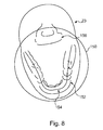
- the shape of the dental arch 152 is thus obtained, as represented seen from above in Figure 8 in which the envelope of the volume 150 is also indicated.
- the procedure continues during the following step S6 with the determination of the median line 154 which extends, in the dental arch, seen from above, between the opposite edges of this.
- this median line 154 ( Figure 8 ) will be used subsequently, when the apparatus will operate in panoramic mode, as a trajectory which the generator and the sensor will travel in order to obtain a panoramic image of the object.
- This trajectory in the shape of a horseshoe will allow the panoramic apparatus 10 to be programmed, in a manner matched and personalized to the object.
- the panoramic apparatuses according to the prior art operate from standard forms of dental arch which are therefore not suitable for the object to be radiographed and are not very precise, unlike the invention.
- the thresholding step forms part of the determination of the trajectory.
- step S6 The trajectory identified in step S6 is sometimes disturbed by different phenomena (metal artefacts such as fillings which are likely to give rise to star-shaped noise around the metal objects, presence of other objects in the field such as the vertebral column 156 in Figure 8 ).
- metal artefacts such as fillings which are likely to give rise to star-shaped noise around the metal objects, presence of other objects in the field such as the vertebral column 156 in Figure 8 ).
- step S7 (optional) correcting this trajectory, for example by smoothing, is provided for.
- step S8 is carried out, during which the sensor is again driven in a 90° pivoting movement in order to bring it into an orientation parallel to the Z-axis (here, the vertical axis).
- the displacement of the slits support 22 is activated in order to bring the slit 18e in front of the window 18b of the generator and thus return to the first mode of operation of the generator.
- the arrangement of the sensor and of the slit of the generator is that of Figure 2 which has already been described.
- the panoramic apparatus can thus be programmed anew to operate in panoramic mode.
- step S6 is used to program the displacement of the assembly formed of the generator provided with the collimation slit and the sensor that have been recently newly positioned parallel to the Z-axis.
- the assembly formed of the generator and the sensor carries out a rotation movement about its vertical axis of rotation which also moves in a controlled manner along this trajectory using the different drive means illustrated in Figure 3 .
- the vertically positioned sensor operating in TDI mode as explained above, acquires image data of the object (here the arch) illuminated by the radiation which produce the sought panoramic image.
- a panoramic image of the arch is obtained from the image data acquired by the sensor during the displacement along the trajectory in the shape of a horseshoe.
- Figure 9 illustrates schematically the panoramic image obtained according to the invention.
- the panoramic image obtained in this way has an optimized quality compared with the techniques known according to the prior art, since the panoramic image is here perfectly matched to the object, in this case the morphology of the patient's jaw.
Landscapes
- Health & Medical Sciences (AREA)
- Life Sciences & Earth Sciences (AREA)
- Medical Informatics (AREA)
- Engineering & Computer Science (AREA)
- Optics & Photonics (AREA)
- Biomedical Technology (AREA)
- Biophysics (AREA)
- High Energy & Nuclear Physics (AREA)
- Oral & Maxillofacial Surgery (AREA)
- Nuclear Medicine, Radiotherapy & Molecular Imaging (AREA)
- Dentistry (AREA)
- Pathology (AREA)
- Radiology & Medical Imaging (AREA)
- Physics & Mathematics (AREA)
- Heart & Thoracic Surgery (AREA)
- Molecular Biology (AREA)
- Surgery (AREA)
- Animal Behavior & Ethology (AREA)
- General Health & Medical Sciences (AREA)
- Public Health (AREA)
- Veterinary Medicine (AREA)
- Apparatus For Radiation Diagnosis (AREA)
Abstract
- means of pivoting the sensor by 90° in order that it is elongated in a direction parallel to the plane P,
- means (22) of switching the generator provided with the said at least one collimation slit (18e, 18f) from the first mode of operation to a second mode of operation so as to produce, in this second mode, an X-ray beam elongated parallel to said direction of the sensor, in order that the sensor positioned in this way is always in correspondence with said beam.
Description
- The present invention relates to a dental radiology apparatus and a method for using this apparatus.
- In the field of dental radiology, radiology apparatuses are known which comprise an X-ray generator and an X-ray sensor each mounted on an arm with an arch-shaped structure, for example within the framework of acquisitions of panoramic or cone beam tomographic images.
- There are apparatuses which allow only panoramic photographs to be taken and others which are capable of producing both panoramic images and cone beam tomographic images.
- In the first type of apparatus, the X-ray generator is provided with a vertical collimation slit and the sensor made in the form of an array of pixels is placed behind a vertical slit arranged opposite the slit of the generator.
- The object to be radiographed is placed between the X-ray generator and the sensor. The X-rays are emitted by the generator in the shape of a cone collimated by the slit in the direction of the object. The sensor receives the rays that have illuminated the object, converts them into electrical signals and provides at the output an image signal of the illuminated object.
- When it is desired to produce, with this type of apparatus, a radiograph of a patient's jaw and in particular to obtain a panoramic image of it, the patient is placed in a sitting or standing position under the arch, between the generator and the sensor.
- The arch pivots about a vertical axis of rotation while the jaw is illuminated by the X-rays in order that the sensor can provide image signals of the patient's jaw.
- Simultaneously with the rotation movement, the axis of rotation of the arch describes a trajectory in the shape of a horseshoe which follows the shape of the patient's dental arch. The zone of interest under investigation (dental arch) covers the jaw.
- However, as the generator and the sensor are placed on either side of the patient, during the rotation bony structures will be superposed on the jaw in the resultant image captured by the sensor.
- In order to limit the effects of this superposition, the pixels of the sensor are shifted at a rate which is governed by the movement and position of the arch. This gives rise to a kinetic blurring such that the undesirable bony structures mentioned above manifest themselves in horizontal bands (streaking) which limit the inconvenience when establishing a diagnosis.
- Moreover, the procedure is such that the pixels of the sensor which are read shifted in the opposite direction to the movement of travel along the trajectory remain fixed in relation to the plane of the arch located in the clear zone.
- This technique, which also contributes to a better dosimetric balance, is known under the name of TDI ("Time Delay Integration").
- The combination of the rotational speed of the arch, the trajectory of the centre of rotation and the translation speed of the pixels on the sensor allows a focal trough to be obtained which has the shape of a band of greater or lesser width which follows the patient's dental arch. The objects located on either side of this focal trough manifest themselves in streaking.
- In the resultant image which presents itself as a developed image of the patient's jaw, the objects located in the focal trough will stand out clearly from the streaking caused by the objects located on either side of this zone, thus facilitating diagnosis.
- The displacement of the sensor and the generator along this trajectory is achieved using a servo-motor mechanism (for example an X,Y-controlled table) placed above the arch and controlled to steer the movement along the X- and Y-axes in the plane of rotation of the sensor and the generator.
- The control of this mechanism requires knowledge of the trajectory matched to the shape of the patient's dental arch.
- When producing panoramic pictures, the operator of the apparatus does not have available information allowing him to control the displacement of the sensor and the generator in a manner suitable for the patient's jaw.
- Thus, the apparatus very often makes several standard forms of dental arch available to the operator from which he selects the one that seems to him to be the most suitable for the patient to be radiographed. These standard forms are based on statistical data of typical morphologies. The apparatus is then programmed in order that the assembly formed of the sensor and the generator travels the trajectory corresponding to the selected standard form of arch (the trajectory is defined as being the median line between the two opposite edges of the standard form of the dental arch).
- However, this solution is not entirely satisfactory, since the sensor and the generator are not positioned in a manner matched to the morphology of the patient's jaw.
- Problems of clarity may result for the zone of interest in the image obtained in this way. For example, the patient's teeth cannot be completely registered in the standard form of arch selected by the operator.
- Moreover, the selection process which has just been described requires the operator to carry out several manoeuvres in order to obtain a panoramic image which, moreover, is sometimes vague over certain zones of the dental arch (incisors, molars...).
- In the light of the above, it would be useful to have available an apparatus and an associated method which allow at least a partial contribution to the resolution of at least one of the problems described above.
- The present invention thus proposes a dental radiology apparatus comprising an X-radiation generator and a sensor opposite it receiving the radiation that has come from the generator, the apparatus being suitable for producing a panoramic image of an object by displacement of the assembly formed of the generator and the sensor along a given trajectory in a plane P, the generator being provided with at least one collimation slit elongated along a Z-axis perpendicular to the plane P so as to produce an X-ray beam elongated along this axis in a first mode of operation, the sensor with an array of pixels being elongated along the Z-axis in correspondence with said beam, characterized in that the apparatus comprises:
- means of pivoting the sensor by 90° in order that it is elongated in a direction parallel to the plane P,
- means of switching the generator provided with the said at least one collimation slit from the first mode of operation to a second mode of operation so as to produce, in this second mode, an X-ray beam elongated parallel to said direction of the sensor, in order that the sensor arranged in this way is always in correspondence with said beam.
- The panoramic apparatus fitted with a sensor suitable for the taking of panoramic photographs is therefore equipped with means allowing the sensor to be displaced from its conventional position (panoramic mode) to a position where it will be able to acquire a three-dimensional model of a part of interest of the object by cone beam tomography. Likewise, the apparatus comprises means allowing the mode of operation of the generator provided with the said at least one slit to be subsequently changed, i.e. the elongated orientation of the X-ray beam to be changed. The elongated orientation of the beam must in fact be matched to the orientation of the sensor after pivoting.
- This new configuration of a panoramic dental radiology apparatus gives the apparatus a new functionality allowing a three-dimensional model of a specific zone of the object to be obtained (by cone beam tomography). This three-dimensional model will be used by the apparatus when it will operate in conventional panoramic mode in order to produce a panoramic image.
- Moreover, the apparatus more particularly comprises:
- means of driving in rotation, about a fixed axis of rotation parallel to the Z-axis, the assembly formed of the generator in the second mode of operation and the sensor arranged parallel to the plane P,
- means of acquiring several image signals of the object illuminated by the collimated radiation for a plurality of angular positions occupied by the generator-sensor assembly during the rotation movement,
- means of obtaining a three-dimensional model of the illuminated object from the set of acquired image signals,
- means of identifying, from the three-dimensional model obtained in this way, a trajectory which the generator-sensor assembly will have to follow during the subsequent production of a panoramic image of the object.
- In this new configuration (different spatial orientation of the sensor and the X-ray beam produced), the panoramic apparatus comprises means allowing it to obtain, by processing of the data provided by cone beam tomography, a trajectory matched to the object to be radiographed. When a panoramic image of this object is developed, the displacement of the apparatus will be guided along this trajectory in order that the sensor and the generator follow the contours of the object as closely as possible, i.e. as faithfully as possible.
- The result is that the panoramic image of the object which will be generated will be of better quality than previously. In fact, it is thus ensured that the object (for example dental arches) is in the focal trough.
- Moreover, the operator will not need to choose from standard types of dental arch, which will limit the risk of errors and manoeuvres.
- According to a characteristic feature, the means of acquiring several image signals comprise means of reading the data captured by the array of pixels of the sensor, said reading means comprising means of grouping the pixels according to a predetermined number of pixels for the purpose of reading the pixels grouped in this way.
- The grouping of pixels allows the dose of X-rays used to operate the apparatus to be reduced.
- Although spatial resolution is lost in the image acquired during the grouping of pixels, this is not harmful taking account of the sought information.
- According to a feature, the means of identifying a trajectory from the obtained three-dimensional model comprise means of thresholding or segmenting the data constituting this three-dimensional model.
- According to a feature, the generator is provided with a single collimation slit and is thus able to produce an X-ray beam elongated in a direction parallel to the plane P by pivoting the generator and the slit by 90°.
- To this end, the apparatus comprises means (for example a motor) of pivoting, on command, the assembly constituted by the generator and its collimation slit.
- According to a feature, the generator is provided with two collimation slits elongated in perpendicular directions which are each able to pass successively, on command, in front of the generator so as to produce an X-ray beam which is elongated along the Z-axis and along an axis perpendicular to the Z-axis respectively.
- To this end, the apparatus comprises means (for example a motor) of displacing, on command, the slits and thus positioning the slit having the suitable direction in front of the exit window of the generator in order to produce the slit elongated along the desired axis.
- According to a feature, the generator is provided with a single collimation slit, the apparatus comprising means of adjusting the elongation of the slit in directions perpendicular to each other.
- Thus, the orientation of the slit in one or other of the directions can be adjusted on command.
- It will be noted that the dimensions of the slit can also be adjusted according to need.
- According to a feature, the adjustment means are independent as regards the directions.
- It is thus possible to choose to elongate the slit in one direction without modifying its elongation in the other direction using the adjustment means specific to each direction.
- According to a feature, the collimation slit is delimited by four edges and the adjustment means are able to displace each of the edges independently of one another.
- This arrangement thus provides a great flexibility of use and a particularly fine adjustment of the distance between the pairs of opposite edges.
- Another object of the invention is a method for producing a panoramic image of an object from a dental radiology apparatus comprising an X-radiation generator and a sensor opposite it receiving the radiation that has come from the generator, the generator being provided with at least one collimation slit elongated along a Z-axis perpendicular to a plane P so as to produce an X-ray beam elongated along this axis in a first mode of operation, the sensor with an array of pixels being elongated along the Z-axis in correspondence with said beam, characterized in that the method comprises the following preliminary steps with a view to operating the apparatus in cone beam tomographic mode in order to obtain a trajectory to be travelled in the plane P by the generator-sensor assembly to produce a panoramic image of the object:
- pivoting of the sensor by 90° in order that it is elongated in a direction parallel to the plane P,
- switching from the first mode of operation of the generator provided with the said at least one collimation slit to a second mode of operation in which an X-ray beam elongated parallel to said direction of the sensor is produced in order that the latter is always in correspondence with said beam.
- This method thus provides for the temporary switching from a panoramic mode of operation to a cone beam tomographic mode of operation in order to acquire data which will be used to improve the operation of the apparatus in panoramic mode and, in particular, to increase the quality of the panoramic images.
- More particularly, the method comprises the following steps, still prior to the acquisition of a panoramic image:
- driving in rotation of the assembly formed of the generator in the second mode of operation and the sensor arranged parallel to the plane P about a fixed axis of rotation parallel to the Z-axis,
- acquisition of several image signals of the object illuminated by the collimated radiation for a plurality of angular positions occupied by the generator-sensor assembly during the rotation movement,
- obtaining, from the set of acquired image signals, of a three-dimensional model of the illuminated object,
- identification, from the three-dimensional model obtained in this way, of a trajectory along which the generator-sensor assembly will move during the subsequent production of a panoramic image of the object.
- When the apparatus is used according to a cone beam tomographic mode of operation, it is thus possible to obtain a three-dimensional model of the illuminated object or of a part or zone of interest of it.
- In order to avoid damaging the dosimetric balance of the set of operations carried out in order to obtain a panoramic image, the doses necessary to obtain this three-dimensional model are reduced.
- This reduction in the dose is made possible by the fact that the three-dimensional model of the object is recorded in a cylinder whose height is too small for the data constituting it to be able to be used for the purpose of diagnosis.
- Moreover, the processing operations (thresholding or segmentation) which will be carried out on the data constituting the three-dimensional model of the object (envelope of the object or of part of it) in order to determine the sought trajectory for the panoramic mode of operation do not require a high-quality image.
- A reduction of the X-ray doses is thus possible, since it will not prevent this trajectory from being obtained.
- The sought trajectory can be defined as being the median line relative to the envelope of the object or of part of the object provided by the aforementioned three-dimensional model.
- It will be noted that it is possible to further reduce the X-ray doses used for the cone beam tomographic mode of operation. To do this, the acquisition of several image signals comprises a step of reading the data captured by the array of pixels which provides for the grouping of the pixels of the sensor according to a predetermined number (such that the group of pixels forms a square) for the purpose of reading the pixels grouped in this way.
- Thus, by way of example, if the pixels are grouped two-by-two, the signal-to-noise ratio is multiplied by four and the X-ray dose is reduced fourfold.
- When the apparatus will subsequently be used according to a panoramic mode of operation, the generator-sensor assembly will move along the trajectory obtained above using the live data of the object, which will guarantee the quality of the panoramic image produced, in particular its clarity.
- According to a feature, the method comprises the following steps:
- pivoting of the sensor by 90° to bring it into a position parallel to the Z-axis,
- switching from the second mode of operation of the generator provided with the said at least one collimation slit to the first mode of operation,
- controlling of the displacement of the assembly formed of the generator provided with the said at least one collimation slit and the sensor arranged parallel to the Z-axis along the previously identified trajectory combined with a rotation movement about an axis parallel to the Z-axis,
- acquisition of a panoramic image of the object during this controlled displacement combined with a shift of the pixels of the sensor.
- It is thus easy to revert to the conventional panoramic mode of operation by activating the 90° pivoting of the sensor and the first mode of operation of the generator provided with the said at least one collimation slit.
- The obtained trajectory thus allows the precise and reliable programming of the displacement of the sensor and the generator in the plane in order to produce a final image of high quality.
- Other details and advantages of the invention will appear during the description given below in non-limitative manner with reference to the attached drawings, in which:
-
Figure 1 is a general schematic view of a dental radiology apparatus according to the invention; -
Figure 2 is a general schematic view showing the arrangement of the sensor and of the vertical slit in position for the panoramic mode of operation; -
Figure 3 is a simplified general schematic view of the displacement table 24 of the apparatus ofFigure 1 ; -
Figure 4 is a general schematic view showing the arrangement of the sensor and of the horizontal slit in position for the mode of operation for determining a trajectory; -
Figures 5a and 5b schematically illustrate the means used to create a single variable-geometry slit; -
Figure 5c illustrates an example of a slit obtained with the arrangements ofFigures 5a and 5b ; -
Figure 6 represents an operating algorithm of the apparatus ofFigure 1 ; -
Figure 7 schematically illustrates the reconstructed volume of a part of theobject 23; -
Figure 8 schematically illustrates, seen from above, the dental arch and the trajectory obtained using the invention; -
Figure 9 is a schematic representation of a panoramic image obtained from the trajectory ofFigure 8 . - As represented in
Figure 1 and designated by thegeneral reference number 10, a dental radiology apparatus according to the invention is an apparatus of the panoramic type. This apparatus allows the production of panoramic images of an object such as a dental arch. The apparatus comprises a fixedcolumn 12, for example a vertical support tube, on which a revolvingradiographic unit 14 is mounted which will now be described. - This unit comprises a
mobile structure 16 in the form of a flattened C (arch) comprising a horizontalcentral beam 16a forming a support which constitutes the body of the C and twovertical arms - An X-ray source or
generator 18 is mounted in fixed manner on thearm 16b, while anX-ray sensor 20 is mounted on thearm 16c. - The
generator 18 and thesensor 20 are thus arranged opposite each other and are in a fixed geometric relation to each other. - The
structure 16 which acts as a support for thegenerator 18 and thesensor 20 constitutes the core of the revolvingradiographic unit 14. - The
radiology apparatus 10 also comprises, in a manner not represented, a lower arm fixed at one end to thecolumn 12. The free end of the arm is equipped with a positioning device allowing the patient's head to be immobilized while radiographic photographs are taken, during the operation of the apparatus. The head is thus interposed between thegenerator 18 and thesensor 20. - The radiation generator is equipped with a
mobile support 22, for example in the form of a portion of a circle (angular sector), fitted against theface 18a of the generator which faces thesensor 20 and in which anopening 18b is made for the emergence of the X-rays from the generator. - The support is positioned in front of this
exit window 18b for the X-rays and comprises several collimation slits, for example two. These slits are intended to each be placed facing thewindow 18b depending on the controlled displacement of the support. - A displacement means such as a
motor 18c allows the displacement of the support which takes place, here in the form of a pivoting about anaxis 18d perpendicular to theface 18a of the generator, to be controlled. - In the example represented, the slits are elongated in directions which are perpendicular to each other: when each slit is arranged in turn in front of the
window 18b, theslit 18e is vertical and theslit 18f is horizontal. - Each slit is, for example, rectangular in shape.
- The collimated X-ray beam thus has the form of a cone which has been truncated by its passage through the slit opposite the rectangular section. This beam is elongated, at its base (in a section parallel to the plane of the slit), in a direction corresponding to the direction in which the slit is elongated.
- In the position represented in
Figure 1 , theslit 18e which is elongated along the Z-axis has been selected (first mode of operation of the generator). - The
sensor 20 attached to thearm 16c is positioned opposite thegenerator 18. It is able, on the one hand, to receive the X-radiation originating from the generator that has illuminated the object placed between generator and sensor and, on the other hand, to transform this radiation attenuated by its passage through the object into an electrical signal representing a radiographic image of this object. - It will be noted that the sensor comprises an array of pixels which is elongated in a longitudinal direction parallel to the Z-axis (
Figure 1 ) and arranged to correspond to the beam that has come from thecollimation slit 18e for this first mode of operation of the apparatus. - This sensor is, for example, a charge transfer sensor of CCD type and its rectangular dimensions are for example 12 cm (height along the Z-axis) x 1 cm (width). An
electronics unit 20a controlling and feeding the sensor is provided behind it. - The apparatus of
Figure 1 is able to operate in known manner in panoramic mode (first mode). - To do this, the assembly comprising the generator and the sensor carried by the arch-shaped structure carries out a displacement in a plane P perpendicular to the Z-axis which, here, is a horizontal plane (
Figure 2 ). The operation of the apparatus would, however, be identical if the Z-axis and the plane P, both perpendicular, adopted a different spatial orientation. - The displacement in the plane P is a movement resulting from a combination of an axis of rotation parallel to the Z-axis and a displacement along a trajectory in the shape of a horseshoe which reproduces the general shape of a dental arch of a patient's
jaw 23. - This trajectory corresponds, in a horizontal plane, to the median line between the two opposite edges of the dental arch.
- The displacement of the generator-sensor assembly is carried out by means of displacement of the load-bearing structure.
- These means are, for example, in the form of an X,Y-controlled displacement table 24 (servo-control mechanism) which is programmed to describe the aforementioned trajectory.
- As represented very schematically in
Figure 3 , the table 24 comprises afirst carriage 30 sliding on twolongitudinal rails motor 36 connected to the carriage by anendless screw 38. - The table also comprises a
second carriage 40 sliding on twolongitudinal rails motor 46 connected to the carriage by anendless screw 48. - The table 24 is integral with the arch-shaped
structure 16 and a drive means 49 such as a motor is connected to thestructure 16 in order to drive this structure in rotation, on command, about the axis ofrotation 51 perpendicular to the plane P and thus perpendicular to the plane defined by the directions A1 and A2. - By controlling the displacement of the
carriages structure 16 describes the sought trajectory (in the shape of a horseshoe) in the plane P. - It will be noted that, during the displacement of the generator and sensor around the object (patient's jaw) in the plane P, the sensor operates in what is called TDI ("Time Delay Integration") mode.
- This mode of operation known per se has the aim of functioning such that the pixels of the mobile sensor which capture the radiation that has illuminated the patient's jaw are regarded as fixed in relation to the jaw.
- To do this, the frequency of reading of the array of pixels is arranged such that the shift of the lines of the array towards the shift register, under the reading pulses of the latter, takes place in a direction opposite to that of the displacement of the sensor.
- The TDI mode thus allows the blurring phenomena in the panoramic image obtained to be avoided.
- The first mode of operation of the apparatus of
Figure 1 which has just been described relates to the panoramic mode. - The apparatus according to the invention is however capable of being used in a second mode of operation in order to determine a trajectory which will be travelled by the sensor and the generator in the panoramic mode of operation.
- To do this, the apparatus comprises means 20b (for example a motor) for pivoting the
sensor 20 ofFigure 2 by 90° in order to bring it into the position illustrated inFigure 4 . - The sensor is thus arranged elongated in a direction parallel to the plane P.
- The apparatus also comprises means adapted in order that the X-ray generator provided, in a general manner, with at least one collimation slit switches from the first mode of operation (slit elongated along the Z-axis in
Figure 2 ) to a second mode of operation in which the slit is elongated in a direction parallel to the plane P and to the longitudinal direction of the sensor. - In this second mode of operation, the generator which is fitted with a slit having such a spatial orientation is capable of producing an X-ray beam elongated, at its base, in this same orientation.
- Thus, the sensor and the slit are always positioned opposite each other, such that the X-ray beam can still reach the sensor after pivoting.
- In the embodiment of
Figure 1 , the radiology apparatus is provided with twocollimation slits slit support 22. - By switching the slits (pivoting of the slits support in the direction indicated by the arrow 25), the
vertical slit 18e ofFigure 2 is replaced by thehorizontal slit 18f which has just positioned itself in front of theexit window 18b. - The
sensor 20 and theslit 18f arranged in this way (Figure 4 ) will then be driven in rotation about an axis of rotation B (vertical) by themeans 49 ofFigure 3 in order to determine the aforementioned trajectory matched to theobject 23, as will be explained below. -
Figures 5a and 5b illustrate a variant allowing a single collimation variable-geometry slit to be produced by replacing theslits Figure 1 . - Adjustment means are provided in order to vary, on command, the geometry of the slit and, in particular, its elongation in two directions perpendicular to each other, for example horizontal and vertical.
- More particularly, the adjustment means suitable for modifying the elongation of the slit in one direction are independent of those suitable for modifying the elongation in the other direction, thus offering a greater flexibility of adjustment.
- In the example illustrated, the radiology apparatus comprises four independent adjustment means 50, 52, 54, 56 for independently varying the position of each of the four
edges - The apparatus comprises a slit support, not represented, for example carried by the
generator 18 ofFigure 1 , or even attached directly to the structure 16 (for example to thearm 16b), which is placed in front of thewindow 18b. - On this support are superposed, in succession, the arrangement of
Figure 5b , then that ofFigure 5a . - These arrangements have not been represented superposed, for the sake of clarity.
- More particularly, the arrangement of
Figure 5a comprises twoedges plates plate - Each pair of
plates - The
second plate teeth - A means of displacing the edge 58 (or 60) comprises a motor 50 (or 52) equipped on its output shaft with a toothed pinion 78 (or 80). This pinion cooperates with the teeth 76 (or 74) to initiate the displacement of the
plates - A guide slot 82 (or 84) is provided in the second plate 72 (or 70) and two guide pins 86, 88 (or 90, 92) integral with the aforementioned support are positioned in this groove in order to longitudinally guide the displacement of the corresponding plate and thus of the corresponding edge.
- This arrangement allows, by adjusting the distance between the
opposite edges - In the same way, the arrangement illustrated in
Figure 5b allows, by adjusting the distance between theopposite edges - Thus, by bringing the
edges edges Figure 5c (like theslit 18e ofFigures 1 and2 ) is thus obtained. - On the other hand, if the
edges edges slit 18f ofFigures 1 and4 is thus obtained. - The different elements represented in
Figure 5b , namely the first andsecond plates 100, 102 (or 104, 106), the grooves 108 (or 110), the motor 54 (or 56) and its toothed pinion 116 (or 118), as well as the guide pins 120, 122 (or 124, 126) in the guide slot 128 (or 130), are identical to the corresponding elements inFigure 5a but are shifted by only 90°. - The
panoramic apparatus 10 which has just been described comprises the means allowing it to produce panoramic images of improved quality compared with the state of the art and its use/mode of operation will now be described. -
Figure 6 represents an algorithm detailing the principal steps of an operating method of theapparatus 10 according to the invention. - This algorithm is for example stored in a storage area of a programmable device (example: a computer of PC type) which controls the operation of the
apparatus 10 and is executed on command. - The method according to the invention can advantageously be used automatically, thus limiting human involvement.
- The algorithm of the method illustrated in
Figure 6 comprises a first step S1 during which the radiology apparatus leaves the panoramic mode (first mode of operation) and switches to a pivoting mode (second mode of operation). - More particularly, during this step the sensor is automatically driven in rotation by the
motor 20b in a 90° pivoting movement from the initial position which it occupies when the apparatus is operating in panoramic mode (Figures 1 and2 ). - The sensor is thus positioned elongated in a direction parallel to the plane P (
Figure 4 ). Similarly, the displacement of theslit support 22 is activated in order to bring theslit 18f in front of thewindow 18b in the second mode of operation of the generator. Thus, the X-ray beam collimated by this slit which is oriented parallel to the plane P and parallel to the sensor is shaped so as to always be in correspondence with the new position of the sensor. The radiation that has come from the generator and been collimated by the slit is therefore always received by the sensor opposite it. - It will be noted that with the variant illustrated in
Figures 5a and 5b the adjustable slit is transformed in order to switch from that ofFigure 2 (Figure 5c ) to that ofFigure 4 by displacing the edges in an suitable manner, as explained above. - During the following step S2 the radiology apparatus is activated in order to change to CBCT ("Cone Beam Computed Tomography") mode of operation.
- It will be noted that the panoramic apparatus is not normally equipped to produce radiographic photographs according to CBCT technology because of the unsuitable shape of its image sensor.
- However, the invention will not allow a complete radiographic photograph to be obtained by this technique but will use this mode of operation, temporarily, only to acquire certain personalized data, not accessible in panoramic mode, which will be used subsequently in this mode.
- Thus, step S2 is followed by a step S3 of acquiring data in cone beam tomographic (CBCT) mode of operation on the object (for example the
object 23 ofFigure 4 ) placed between the generator and the sensor, and more particularly the patient's jaw. - In particular, during step S3 the assembly formed of the generator equipped with its collimation slit and the sensor is driven in rotation in the plane P, about an axis B parallel to the Z-axis. During this rotation movement, this assembly occupies a plurality of successive angular positions for each of which image signals of the object illuminated by the collimated radiation are acquired by the sensor.
- During this movement, the centre of rotation of the generator-sensor assembly is fixed. This centre is for example positioned on the
object 23. - For each angular position of this assembly, the data captured by the sensor represent a projection of the object along the generator-image sensor axis.
- Thus, at the end of a complete rotation of the generator-sensor assembly, a set of image signals each representing a projection of the
object 23 illuminated by the beam for example is obtained and, for example, 360 projections of this object in the case where a photograph is taken for each degree of rotation. - Each analogue image signal is captured by the array of pixels of the sensor, transformed into an analogue electrical signal by the sensor, then converted into a digital signal.
- It will be noted that in order to reduce the dose of X-radiation used to obtain these signals, it may be advisable to use the capability of the sensor to group the pixels of the array according to a predetermined number, for example in twos or threes, for the purpose of reading.
- In fact, by reading the pixels per group of two or three depending on the chosen grouping ("binning"), the array reading noise is reduced and the signal-to-noise ratio of the sensor is increased, thus allowing the dose of radiation to be reduced.
- During the following step S4 the volume of the illuminated part of the object is reconstructed from the set of image signals obtained previously and the reconstructed volume is in the form of a
cylinder 150 of small height. The height or thickness of the cylinder z1 corresponds to the smallest dimension of the sensor (width), while the diameter of the cylinder z1, for its part, is limited by the largest dimension of the sensor (length) apart from enlargement coefficients. - By way of example, the height of the cylinder ranges from some hundreds of micrometres to some millimetres.
- The
volume 150 is represented inFigure 7 and it surrounds the patient's dental arch. - This
reconstructed volume 150 provides a three-dimensional model of the shape of the illuminated object which contains sufficient information to determine the sought data specific to the object. - It will be noted that the three-dimensional model of the object is vertically centred (along the Z-axis) in relation to the zone of interest. This centring is carried out when the generator-sensor assembly is positioned before the assembly is rotated (step S2). The zone of interest in the example described is the "occlusal plane" of the patient's jaw, that is to say the contact interface between the teeth.
- During the following step S5 the object or the part of the object of interest, namely in this case the patient's dental arch, is defined from the volume reconstructed in this way.
- To do this, what is called a "thresholding" or "segmentation" operation is carried out on the data in the reconstructed volume.
- The procedure continues, for example by thresholding, by analyzing the differences in the shades of grey between the teeth and their environment which represent differences in density and the shape of the dental arch is deduced from it in three dimensions.
- The shape of the
dental arch 152 is thus obtained, as represented seen from above inFigure 8 in which the envelope of thevolume 150 is also indicated. - By extracting horizontal sections from the shape of the
dental arch 152, the procedure continues during the following step S6 with the determination of themedian line 154 which extends, in the dental arch, seen from above, between the opposite edges of this. - The determination of this median line corresponds to the identification of a "trajectory".
- More particularly, this median line 154 (
Figure 8 ) will be used subsequently, when the apparatus will operate in panoramic mode, as a trajectory which the generator and the sensor will travel in order to obtain a panoramic image of the object. - This trajectory in the shape of a horseshoe will allow the
panoramic apparatus 10 to be programmed, in a manner matched and personalized to the object. The panoramic apparatuses according to the prior art operate from standard forms of dental arch which are therefore not suitable for the object to be radiographed and are not very precise, unlike the invention. - It will be noted that the thresholding step forms part of the determination of the trajectory.
- The trajectory identified in step S6 is sometimes disturbed by different phenomena (metal artefacts such as fillings which are likely to give rise to star-shaped noise around the metal objects, presence of other objects in the field such as the
vertebral column 156 inFigure 8 ). - In order to improve the accuracy of the trajectory obtained in step S6, a step S7 (optional) correcting this trajectory, for example by smoothing, is provided for.
- When the corrected trajectory has been obtained, the following step S8 is carried out, during which the sensor is again driven in a 90° pivoting movement in order to bring it into an orientation parallel to the Z-axis (here, the vertical axis).
- Similarly, the displacement of the slits support 22 is activated in order to bring the
slit 18e in front of thewindow 18b of the generator and thus return to the first mode of operation of the generator. The arrangement of the sensor and of the slit of the generator is that ofFigure 2 which has already been described. - After this pivoting step, the panoramic apparatus can thus be programmed anew to operate in panoramic mode.
- On this occasion, the trajectory obtained in step S6, optionally corrected in step S7, is used to program the displacement of the assembly formed of the generator provided with the collimation slit and the sensor that have been recently newly positioned parallel to the Z-axis.
- During the operation of the apparatus in parameterized panoramic mode with a more suitable trajectory than in the prior art, the assembly formed of the generator and the sensor carries out a rotation movement about its vertical axis of rotation which also moves in a controlled manner along this trajectory using the different drive means illustrated in
Figure 3 . - During this displacement, the vertically positioned sensor, operating in TDI mode as explained above, acquires image data of the object (here the arch) illuminated by the radiation which produce the sought panoramic image.
- In known manner, a panoramic image of the arch is obtained from the image data acquired by the sensor during the displacement along the trajectory in the shape of a horseshoe.
- By combining the movements of rotation of the arch 16, displacement of the centre of rotation of the arch using the displacement table 24, sliding of the pixels of the sensor 20 (TDI mode), a virtual rotation point is recreated which is contained at any time in the focal trough. Thus, the anatomical structures located outside this manifest themselves in a streaking which does not harm the diagnosis, and the structures contained in the focal trough appear clear.
-
Figure 9 illustrates schematically the panoramic image obtained according to the invention. - It will be noted that the panoramic image obtained in this way has an optimized quality compared with the techniques known according to the prior art, since the panoramic image is here perfectly matched to the object, in this case the morphology of the patient's jaw.
- Moreover, the method which has just been described avoids numerous manoeuvres by the operator, manoeuvres which moreover manifest themselves in inaccurate results.
- It will be noted that when the apparatus is operating in CBCT mode the aim is not to obtain a high-quality image using this mode. It is for this reason that the dose of radiation can be reduced in this mode of operation.
Claims (14)
- Dental radiology apparatus (10) comprising an X-radiation generator (18) and a sensor (20) opposite it receiving the radiation that has come from the generator, the apparatus being suitable for producing a panoramic image of an object by displacement of the assembly formed of the generator and the sensor along a given trajectory in a plane (P), the generator being provided with at least one collimation slit (18e, 18f) elongated along an axis (Z) perpendicular to the plane (P) so as to produce an X-ray beam elongated along this axis in a first mode of operation, the sensor with an array of pixels being elongated along the Z-axis in correspondence with said beam, characterized in that the apparatus comprises:- means of pivoting the sensor by 90° in order that it is elongated in a direction parallel to the plane P,- means (22) of switching the generator provided with the said at least one collimation slit (18e, 18f) from the first mode of operation to a second mode of operation so as to produce, in this second mode, an X-ray beam elongated parallel to said direction of the sensor, in order that the sensor arranged in this way is always in correspondence with said beam.
- Apparatus according to claim 1, characterized in that it comprises:- means (49) of driving in rotation, about a fixed axis of rotation parallel to the axis (Z), the assembly formed of the generator in the second mode of operation and the sensor arranged parallel to the plane (P),- means of acquiring several image signals of the object illuminated by the collimated radiation for a plurality of angular positions occupied by the generator-sensor assembly during the rotation movement,- means of obtaining a three-dimensional model of the illuminated object from the set of acquired image signals,- means of identifying, from the three-dimensional model obtained in this way, a trajectory which the generator-sensor assembly will have to follow during the subsequent production of a panoramic image of the object.
- Apparatus according to claim 2, characterized in that the means of acquiring several image signals comprise means of reading the data captured by the array of pixels of the sensor, said reading means comprising means of grouping the pixels according to a predetermined number of pixels for the purpose of reading the pixels grouped in this way.
- Apparatus according to claim 2 or 3, characterized in that the means of identifying a trajectory from the obtained three-dimensional model comprise means of thresholding or segmenting the data constituting this three-dimensional model.
- Apparatus according to one of claims 1 to 4, characterized in that the generator (18) is provided with a single collimation slit and is thus able to produce an X-ray beam elongated in a direction parallel to the plane (P) by pivoting the generator and the slit by 90°.
- Apparatus according to one of claims 1 to 4, characterized in that the generator is provided with two collimation slits (18e, 18f) elongated in perpendicular directions which are each able to pass successively, on command, in front of the generator so as to produce an X-ray beam which is elongated along the Z-axis and along an axis perpendicular to the Z-axis respectively.
- Apparatus according to one of claims 1 to 4, characterized in that the generator (18) is provided with a single collimation slit, the apparatus comprising means of adjusting (74, 76, 78, 80, 108, 110, 116, 118) the elongation of the slit in directions perpendicular to each other.
- Apparatus according to claim 7, characterized in that the adjustment means are independent as regards the directions.
- Apparatus according to claim 7 or 8, characterized in that the collimation slit is delimited by four edges (58, 60, 62, 64) and the adjustment means are able to displace each of the edges independently of one another.
- Method for producing a panoramic image of an object from a dental radiology apparatus comprising an X-radiation generator (18) and a sensor (20) opposite it receiving the radiation that has come from the generator, the generator being provided with at least one collimation slit (18e, 18f) elongated along an axis (Z) perpendicular to a plane (P) so as to produce an X-ray beam elongated along this axis in a first mode of operation, the sensor with an array of pixels being elongated along the axis (Z) in correspondence with said beam, characterized in that the method comprises the following preliminary steps with a view to operating the apparatus in cone beam tomographic mode in order to obtain a trajectory to be travelled in the plane (P) by the generator-sensor assembly to produce a panoramic image of the object:- pivoting (S1) the sensor by 90° in order that it is elongated in a direction parallel to the plane (P),- switching (S2) from the first mode of operation of the generator provided with the said at least one collimation slit to a second mode of operation in which an X-ray beam elongated parallel to said direction of the sensor is produced in order that the latter is always in correspondence with said beam.
- Method according to claim 10, characterized in that it comprises the following steps:- driving in rotation of the assembly formed of the generator in the second mode of operation and the sensor arranged parallel to the plane (P) about a fixed axis of rotation parallel to the axis (Z),- acquisition of (S3) several image signals of the object illuminated by the collimated radiation for a plurality of angular positions occupied by the generator-sensor assembly during the rotation movement,- obtaining (S4), from the set of acquired image signals, of a three-dimensional model of the illuminated object,- identification (S6), from the three-dimensional model obtained in this way, of a trajectory along which the generator-sensor assembly will move during the subsequent production of a panoramic image of the object.
- Method according to claim 11, characterized in that the acquisition of several image signals comprises a step of reading the data captured by the array of pixels of the sensor which comprises the grouping of pixels according to a predetermined number of pixels for the purpose of reading the pixels grouped in this way.
- Method according to claim 11 or 12, characterized in that the identification of a trajectory from the three-dimensional model obtained comprises a step of thresholding (S5) or segmenting the data constituting this three-dimensional model.
- Method according to one of claims 11 to 13, characterized in that it comprises the following steps:- pivoting (S8) of the sensor by 90° to bring it into a position parallel to the axis (Z),- switching from the second mode of operation of the generator provided with the said at least one collimation slit to the first mode of operation,- controlling of the displacement of the assembly formed of the generator provided with the said at least one collimation slit and the sensor arranged parallel to the axis (Z) along the previously identified trajectory combined with a rotation movement about an axis parallel to the axis (Z),- acquisition of a panoramic image of the object during this controlled displacement combined with a shift of the pixels of the sensor.
Applications Claiming Priority (1)
| Application Number | Priority Date | Filing Date | Title |
|---|---|---|---|
| FR0855685A FR2938183B1 (en) | 2008-08-22 | 2008-08-22 | PANORAMIC DENTAL RADIOLOGY APPARATUS AND METHOD OF USE THEREOF |
Publications (2)
| Publication Number | Publication Date |
|---|---|
| EP2156792A1 true EP2156792A1 (en) | 2010-02-24 |
| EP2156792B1 EP2156792B1 (en) | 2013-03-13 |
Family
ID=40419086
Family Applications (1)
| Application Number | Title | Priority Date | Filing Date |
|---|---|---|---|
| EP09168422A Not-in-force EP2156792B1 (en) | 2008-08-22 | 2009-08-21 | Panoramic dental radiology apparatus and associated method of use |
Country Status (5)
| Country | Link |
|---|---|
| US (1) | US8503604B2 (en) |
| EP (1) | EP2156792B1 (en) |
| JP (1) | JP5547443B2 (en) |
| KR (1) | KR101642987B1 (en) |
| FR (1) | FR2938183B1 (en) |
Cited By (2)
| Publication number | Priority date | Publication date | Assignee | Title |
|---|---|---|---|---|
| EP2589339A1 (en) * | 2011-11-02 | 2013-05-08 | J. Morita Manufacturing Corporation | Panoramic tomography X-ray apparatus and image processing device |
| EP3453334A1 (en) * | 2017-08-23 | 2019-03-13 | J. Morita Manufacturing Corporation | X-ray imaging apparatus and x-ray imaging method |
Families Citing this family (19)
| Publication number | Priority date | Publication date | Assignee | Title |
|---|---|---|---|---|
| JP5618293B2 (en) * | 2010-09-22 | 2014-11-05 | 朝日レントゲン工業株式会社 | Medical X-ray equipment |
| ES2788102T3 (en) * | 2010-12-22 | 2020-10-20 | Trophy | Digital detector |
| FR2982759B1 (en) | 2011-11-17 | 2013-11-29 | Trophy | PANORAMIC DENTAL RADIOLOGY APPARATUS |
| KR101361076B1 (en) * | 2012-03-12 | 2014-02-11 | (주)제노레이 | X-ray Imaging System |
| FR2992877B1 (en) * | 2012-07-06 | 2015-07-03 | Phenix Systems | LASER BEAM DRIVING METHOD FOR MANUFACTURING THREE DIMENSIONAL OBJECTS WITH SUPERIMPOSED LAYERS. |
| EP2892432B1 (en) * | 2012-09-07 | 2022-12-28 | Trophy | Apparatus for partial ct imaging |
| KR20150088679A (en) * | 2014-01-24 | 2015-08-03 | 주식회사바텍 | Apparatus for Obtaining Computed Tomography |
| US9724055B2 (en) | 2014-03-07 | 2017-08-08 | Elwha Llc | Systems, devices, and methods for lowering dental x-ray dosage including feedback sensors |
| CN103908288B (en) * | 2014-03-21 | 2016-03-02 | 北京工业大学 | Along the digitized dentistry surface fault panoramic X-ray machine of true dental arch track scanning |
| US9888891B2 (en) | 2014-06-26 | 2018-02-13 | Palodex Group Oy | X-ray imaging unit for medical imaging |
| US10405815B2 (en) | 2014-07-28 | 2019-09-10 | Vatech Co., Ltd. | X-ray imaging device |
| CN105741239B (en) * | 2014-12-11 | 2018-11-30 | 合肥美亚光电技术股份有限公司 | Generation method, device and the panorama machine for shooting tooth of tooth panoramic picture |
| US10049467B2 (en) * | 2015-03-18 | 2018-08-14 | Vatech Co., Ltd. | Apparatus and method for reconstructing medical image |
| KR102117290B1 (en) * | 2015-03-18 | 2020-06-01 | 주식회사바텍 | Medical image reconstruction device and method |
| US11872056B2 (en) | 2015-10-09 | 2024-01-16 | Koninklijke Philips N.V. | Advanced control features for steering devices for intravascular devices and associated systems and methods |
| ITUA20162102A1 (en) * | 2016-03-30 | 2017-09-30 | Cefla S C | BEAM RESTRICTION DEVICE FOR RADIOGRAPHIC EQUIPMENT |
| US11341609B2 (en) * | 2017-09-28 | 2022-05-24 | 3Shape A/S | Method and system for generating a panoramic image |
| KR102026716B1 (en) | 2017-11-15 | 2019-09-30 | 주식회사 에스엠디솔루션 | X-ray imaging apparatus and imaging method using the apparatus |
| KR102026715B1 (en) | 2017-11-15 | 2019-09-30 | 주식회사 에스엠디솔루션 | Cable alignment device, x-ray imaging apparatus comprising the cable alignment device and imaging method using the x-ray imaging apparatus |
Citations (3)
| Publication number | Priority date | Publication date | Assignee | Title |
|---|---|---|---|---|
| US6289074B1 (en) * | 1998-09-02 | 2001-09-11 | J. Morita Manufacturing Corporation | X-ray computed tomography method and system |
| WO2006109802A1 (en) * | 2005-04-11 | 2006-10-19 | J. Morita Manufacturing Corporation | X-ray ct imaging unit and x-ray imager |
| WO2008092009A2 (en) * | 2007-01-24 | 2008-07-31 | Imaging Sciences International Llc | Adjustable scanner |
Family Cites Families (26)
| Publication number | Priority date | Publication date | Assignee | Title |
|---|---|---|---|---|
| EP0340349B1 (en) * | 1988-05-06 | 1998-10-21 | Dentsply Research & Development Corp. | Dental X-ray apparatus for panoramic tomography |
| JP3291406B2 (en) * | 1995-02-09 | 2002-06-10 | 株式会社モリタ製作所 | Panoramic X-ray equipment |
| JP3319905B2 (en) * | 1995-03-24 | 2002-09-03 | 株式会社モリタ製作所 | Digital X-ray equipment |
| US7136452B2 (en) * | 1995-05-31 | 2006-11-14 | Goldpower Limited | Radiation imaging system, device and method for scan imaging |
| JP3331284B2 (en) | 1995-11-06 | 2002-10-07 | 株式会社モリタ製作所 | Medical X-ray tomography system |
| JP3807833B2 (en) * | 1996-12-10 | 2006-08-09 | 株式会社モリタ製作所 | X-ray equipment |
| JP3743594B2 (en) * | 1998-03-11 | 2006-02-08 | 株式会社モリタ製作所 | CT imaging device |
| KR100338974B1 (en) * | 1999-03-15 | 2002-05-31 | 최은백, 이찬경 | Simulation method for identifying bone density of mandible or maxilla and recording media storing program to perform the same |
| US6493415B1 (en) * | 1999-03-25 | 2002-12-10 | Nihon University | X-ray computed tomography method and apparatus |
| JP2001284210A (en) * | 2000-03-30 | 2001-10-12 | Canon Inc | Exposure apparatus, device manufacturing method, semiconductor manufacturing factory, and maintenance method of exposure apparatus |
| JP3926120B2 (en) * | 2001-02-16 | 2007-06-06 | 株式会社モリタ製作所 | X-ray imaging position setting means for an object, and X-ray imaging apparatus provided with this means |
| JP2003175031A (en) * | 2001-10-02 | 2003-06-24 | Morita Mfg Co Ltd | Digital X-ray panoramic imaging device |
| US7421059B2 (en) * | 2002-04-11 | 2008-09-02 | J. Morita Manufacturing Corporation | X-ray computer tomography apparatus |
| JP2006061501A (en) * | 2004-08-27 | 2006-03-09 | Morita Mfg Co Ltd | X-ray equipment |
| FI118413B (en) * | 2005-04-11 | 2007-11-15 | Planmeca Oy | Computed tomography system |
| US7336763B2 (en) * | 2005-05-02 | 2008-02-26 | Oy Ajat Ltd | Dental extra-oral x-ray imaging system and method |
| KR100794563B1 (en) * | 2005-08-08 | 2008-01-17 | 주식회사바텍 | Panorama and Citi X-ray System |
| KR100707796B1 (en) * | 2005-08-08 | 2007-04-13 | 주식회사바텍 | Panorama and Citi X-ray System |
| WO2007046372A1 (en) * | 2005-10-17 | 2007-04-26 | J. Morita Manufacturing Corporation | Medical digital x-ray imager and medical digital x-ray sensor |
| JP4738152B2 (en) * | 2005-12-02 | 2011-08-03 | 富士通株式会社 | Simulation program to support dental treatment |
| JP4758747B2 (en) * | 2005-12-09 | 2011-08-31 | 株式会社日立メディコ | X-ray measuring apparatus, X-ray measuring method and X-ray measuring program |
| DK1815794T3 (en) * | 2006-02-01 | 2016-02-01 | Dental Imaging Technologies Corp | Dental X-ray device and method for positioning a patient therein |
| JP4823780B2 (en) * | 2006-06-19 | 2011-11-24 | 株式会社日立メディコ | Panoramic tomographic image generation apparatus and panoramic tomographic image generation program |
| JP2008229322A (en) * | 2007-02-22 | 2008-10-02 | Morita Mfg Co Ltd | Image processing method, image display method, image processing program, storage medium, image processing apparatus, X-ray imaging apparatus |
| US7715526B2 (en) * | 2008-03-13 | 2010-05-11 | Oy Ajat Limited | Single sensor multi-functional dental extra-oral x-ray imaging system and method |
| FR2938182B1 (en) * | 2008-08-22 | 2010-11-19 | Trophy | DENTAL RADIOLOGY APPARATUS AND METHOD OF USE THEREOF |
-
2008
- 2008-08-22 FR FR0855685A patent/FR2938183B1/en not_active Expired - Fee Related
-
2009
- 2009-08-21 EP EP09168422A patent/EP2156792B1/en not_active Not-in-force
- 2009-08-21 KR KR1020090077861A patent/KR101642987B1/en not_active Expired - Fee Related
- 2009-08-24 JP JP2009193280A patent/JP5547443B2/en not_active Expired - Fee Related
- 2009-08-24 US US12/546,137 patent/US8503604B2/en not_active Expired - Fee Related
Patent Citations (4)
| Publication number | Priority date | Publication date | Assignee | Title |
|---|---|---|---|---|
| US6289074B1 (en) * | 1998-09-02 | 2001-09-11 | J. Morita Manufacturing Corporation | X-ray computed tomography method and system |
| WO2006109802A1 (en) * | 2005-04-11 | 2006-10-19 | J. Morita Manufacturing Corporation | X-ray ct imaging unit and x-ray imager |
| US20090052616A1 (en) * | 2005-04-11 | 2009-02-26 | J. Morita Manufacturing Corporation | Unit for X-Ray CT Imaging and X-Ray Imaging Apparatus |
| WO2008092009A2 (en) * | 2007-01-24 | 2008-07-31 | Imaging Sciences International Llc | Adjustable scanner |
Cited By (4)
| Publication number | Priority date | Publication date | Assignee | Title |
|---|---|---|---|---|
| EP2589339A1 (en) * | 2011-11-02 | 2013-05-08 | J. Morita Manufacturing Corporation | Panoramic tomography X-ray apparatus and image processing device |
| US9119575B2 (en) | 2011-11-02 | 2015-09-01 | J. Morita Manufacturing Corporation | Panoramic tomography X-ray apparatus and image processing device |
| EP3453334A1 (en) * | 2017-08-23 | 2019-03-13 | J. Morita Manufacturing Corporation | X-ray imaging apparatus and x-ray imaging method |
| US10806423B2 (en) | 2017-08-23 | 2020-10-20 | J. Morita Manufacturing Corporation | X-ray imaging apparatus and x-ray imaging method |
Also Published As
| Publication number | Publication date |
|---|---|
| EP2156792B1 (en) | 2013-03-13 |
| JP2010046486A (en) | 2010-03-04 |
| KR101642987B1 (en) | 2016-07-26 |
| FR2938183A1 (en) | 2010-05-14 |
| US8503604B2 (en) | 2013-08-06 |
| KR20100023785A (en) | 2010-03-04 |
| JP5547443B2 (en) | 2014-07-16 |
| US20100074403A1 (en) | 2010-03-25 |
| FR2938183B1 (en) | 2011-12-09 |
Similar Documents
| Publication | Publication Date | Title |
|---|---|---|
| EP2156792B1 (en) | Panoramic dental radiology apparatus and associated method of use | |
| EP2156791B1 (en) | Dental radiology apparatus and associated method of use | |
| JP7295917B2 (en) | X-ray equipment for medical diagnostic imaging | |
| US7463715B2 (en) | System and method for real time dual energy x-ray image acquisition | |
| US9743893B2 (en) | Dental imaging with photon-counting detector | |
| US11154260B2 (en) | Apparatus for partial CT imaging comprising a collimator to center a radiation beam toward a region of interest spaced apart from a rotation axis | |
| US11793476B2 (en) | Method and a system for obtaining operating parameters for x ray data acquisition | |
| EP3574839B1 (en) | Dental imaging with photon-counting detector | |
| US10456097B2 (en) | X-ray generation apparatus for intra-oral X-ray imaging, guide holder, and intra-oral X-ray imaging system comprising same | |
| CN106999142B (en) | X-ray imaging device | |
| US9066687B2 (en) | Panoramic dental x-ray unit | |
| US10390776B2 (en) | Three-dimentional serial focused intraoral digital tomosynthesis scanner and controlling method thereof | |
| KR102304968B1 (en) | Method for capturing a three-dimensional x-ray image | |
| WO2017111863A1 (en) | Method and device for creating a cephalometric image |
Legal Events
| Date | Code | Title | Description |
|---|---|---|---|
| PUAI | Public reference made under article 153(3) epc to a published international application that has entered the european phase |
Free format text: ORIGINAL CODE: 0009012 |
|
| AK | Designated contracting states |
Kind code of ref document: A1 Designated state(s): AT BE BG CH CY CZ DE DK EE ES FI FR GB GR HR HU IE IS IT LI LT LU LV MC MK MT NL NO PL PT RO SE SI SK SM TR |
|
| AX | Request for extension of the european patent |
Extension state: AL BA RS |
|
| 17P | Request for examination filed |
Effective date: 20100802 |
|
| 17Q | First examination report despatched |
Effective date: 20100827 |
|
| GRAP | Despatch of communication of intention to grant a patent |
Free format text: ORIGINAL CODE: EPIDOSNIGR1 |
|
| GRAS | Grant fee paid |
Free format text: ORIGINAL CODE: EPIDOSNIGR3 |
|
| GRAA | (expected) grant |
Free format text: ORIGINAL CODE: 0009210 |
|
| AK | Designated contracting states |
Kind code of ref document: B1 Designated state(s): AT BE BG CH CY CZ DE DK EE ES FI FR GB GR HR HU IE IS IT LI LT LU LV MC MK MT NL NO PL PT RO SE SI SK SM TR |
|
| REG | Reference to a national code |
Ref country code: GB Ref legal event code: FG4D |
|
| REG | Reference to a national code |
Ref country code: CH Ref legal event code: EP Ref country code: AT Ref legal event code: REF Ref document number: 600305 Country of ref document: AT Kind code of ref document: T Effective date: 20130315 |
|
| REG | Reference to a national code |
Ref country code: IE Ref legal event code: FG4D |
|
| REG | Reference to a national code |
Ref country code: DE Ref legal event code: R096 Ref document number: 602009013845 Country of ref document: DE Effective date: 20130508 |
|
| PG25 | Lapsed in a contracting state [announced via postgrant information from national office to epo] |
Ref country code: ES Free format text: LAPSE BECAUSE OF FAILURE TO SUBMIT A TRANSLATION OF THE DESCRIPTION OR TO PAY THE FEE WITHIN THE PRESCRIBED TIME-LIMIT Effective date: 20130624 Ref country code: BG Free format text: LAPSE BECAUSE OF FAILURE TO SUBMIT A TRANSLATION OF THE DESCRIPTION OR TO PAY THE FEE WITHIN THE PRESCRIBED TIME-LIMIT Effective date: 20130613 Ref country code: LT Free format text: LAPSE BECAUSE OF FAILURE TO SUBMIT A TRANSLATION OF THE DESCRIPTION OR TO PAY THE FEE WITHIN THE PRESCRIBED TIME-LIMIT Effective date: 20130313 Ref country code: SE Free format text: LAPSE BECAUSE OF FAILURE TO SUBMIT A TRANSLATION OF THE DESCRIPTION OR TO PAY THE FEE WITHIN THE PRESCRIBED TIME-LIMIT Effective date: 20130313 Ref country code: NO Free format text: LAPSE BECAUSE OF FAILURE TO SUBMIT A TRANSLATION OF THE DESCRIPTION OR TO PAY THE FEE WITHIN THE PRESCRIBED TIME-LIMIT Effective date: 20130613 |
|
| REG | Reference to a national code |
Ref country code: AT Ref legal event code: MK05 Ref document number: 600305 Country of ref document: AT Kind code of ref document: T Effective date: 20130313 |
|
| REG | Reference to a national code |
Ref country code: NL Ref legal event code: VDEP Effective date: 20130313 |
|
| REG | Reference to a national code |
Ref country code: LT Ref legal event code: MG4D |
|
| PG25 | Lapsed in a contracting state [announced via postgrant information from national office to epo] |
Ref country code: LV Free format text: LAPSE BECAUSE OF FAILURE TO SUBMIT A TRANSLATION OF THE DESCRIPTION OR TO PAY THE FEE WITHIN THE PRESCRIBED TIME-LIMIT Effective date: 20130313 Ref country code: SI Free format text: LAPSE BECAUSE OF FAILURE TO SUBMIT A TRANSLATION OF THE DESCRIPTION OR TO PAY THE FEE WITHIN THE PRESCRIBED TIME-LIMIT Effective date: 20130313 Ref country code: GR Free format text: LAPSE BECAUSE OF FAILURE TO SUBMIT A TRANSLATION OF THE DESCRIPTION OR TO PAY THE FEE WITHIN THE PRESCRIBED TIME-LIMIT Effective date: 20130614 |
|
| PG25 | Lapsed in a contracting state [announced via postgrant information from national office to epo] |
Ref country code: BE Free format text: LAPSE BECAUSE OF FAILURE TO SUBMIT A TRANSLATION OF THE DESCRIPTION OR TO PAY THE FEE WITHIN THE PRESCRIBED TIME-LIMIT Effective date: 20130313 Ref country code: HR Free format text: LAPSE BECAUSE OF FAILURE TO SUBMIT A TRANSLATION OF THE DESCRIPTION OR TO PAY THE FEE WITHIN THE PRESCRIBED TIME-LIMIT Effective date: 20130313 |
|
| PG25 | Lapsed in a contracting state [announced via postgrant information from national office to epo] |
Ref country code: CZ Free format text: LAPSE BECAUSE OF FAILURE TO SUBMIT A TRANSLATION OF THE DESCRIPTION OR TO PAY THE FEE WITHIN THE PRESCRIBED TIME-LIMIT Effective date: 20130313 Ref country code: EE Free format text: LAPSE BECAUSE OF FAILURE TO SUBMIT A TRANSLATION OF THE DESCRIPTION OR TO PAY THE FEE WITHIN THE PRESCRIBED TIME-LIMIT Effective date: 20130313 Ref country code: NL Free format text: LAPSE BECAUSE OF FAILURE TO SUBMIT A TRANSLATION OF THE DESCRIPTION OR TO PAY THE FEE WITHIN THE PRESCRIBED TIME-LIMIT Effective date: 20130313 Ref country code: IS Free format text: LAPSE BECAUSE OF FAILURE TO SUBMIT A TRANSLATION OF THE DESCRIPTION OR TO PAY THE FEE WITHIN THE PRESCRIBED TIME-LIMIT Effective date: 20130713 Ref country code: SK Free format text: LAPSE BECAUSE OF FAILURE TO SUBMIT A TRANSLATION OF THE DESCRIPTION OR TO PAY THE FEE WITHIN THE PRESCRIBED TIME-LIMIT Effective date: 20130313 Ref country code: AT Free format text: LAPSE BECAUSE OF FAILURE TO SUBMIT A TRANSLATION OF THE DESCRIPTION OR TO PAY THE FEE WITHIN THE PRESCRIBED TIME-LIMIT Effective date: 20130313 Ref country code: RO Free format text: LAPSE BECAUSE OF FAILURE TO SUBMIT A TRANSLATION OF THE DESCRIPTION OR TO PAY THE FEE WITHIN THE PRESCRIBED TIME-LIMIT Effective date: 20130313 Ref country code: PT Free format text: LAPSE BECAUSE OF FAILURE TO SUBMIT A TRANSLATION OF THE DESCRIPTION OR TO PAY THE FEE WITHIN THE PRESCRIBED TIME-LIMIT Effective date: 20130715 |
|
| PG25 | Lapsed in a contracting state [announced via postgrant information from national office to epo] |
Ref country code: CY Free format text: LAPSE BECAUSE OF FAILURE TO SUBMIT A TRANSLATION OF THE DESCRIPTION OR TO PAY THE FEE WITHIN THE PRESCRIBED TIME-LIMIT Effective date: 20130313 Ref country code: PL Free format text: LAPSE BECAUSE OF FAILURE TO SUBMIT A TRANSLATION OF THE DESCRIPTION OR TO PAY THE FEE WITHIN THE PRESCRIBED TIME-LIMIT Effective date: 20130313 |
|
| PLBE | No opposition filed within time limit |
Free format text: ORIGINAL CODE: 0009261 |
|
| STAA | Information on the status of an ep patent application or granted ep patent |
Free format text: STATUS: NO OPPOSITION FILED WITHIN TIME LIMIT |
|
| PG25 | Lapsed in a contracting state [announced via postgrant information from national office to epo] |
Ref country code: DK Free format text: LAPSE BECAUSE OF FAILURE TO SUBMIT A TRANSLATION OF THE DESCRIPTION OR TO PAY THE FEE WITHIN THE PRESCRIBED TIME-LIMIT Effective date: 20130313 |
|
| 26N | No opposition filed |
Effective date: 20131216 |
|
| PG25 | Lapsed in a contracting state [announced via postgrant information from national office to epo] |
Ref country code: IT Free format text: LAPSE BECAUSE OF FAILURE TO SUBMIT A TRANSLATION OF THE DESCRIPTION OR TO PAY THE FEE WITHIN THE PRESCRIBED TIME-LIMIT Effective date: 20130313 |
|
| REG | Reference to a national code |
Ref country code: DE Ref legal event code: R097 Ref document number: 602009013845 Country of ref document: DE Effective date: 20131216 |
|
| REG | Reference to a national code |
Ref country code: CH Ref legal event code: PL |
|
| PG25 | Lapsed in a contracting state [announced via postgrant information from national office to epo] |
Ref country code: LI Free format text: LAPSE BECAUSE OF NON-PAYMENT OF DUE FEES Effective date: 20130831 Ref country code: MC Free format text: LAPSE BECAUSE OF FAILURE TO SUBMIT A TRANSLATION OF THE DESCRIPTION OR TO PAY THE FEE WITHIN THE PRESCRIBED TIME-LIMIT Effective date: 20130313 Ref country code: CH Free format text: LAPSE BECAUSE OF NON-PAYMENT OF DUE FEES Effective date: 20130831 |
|
| REG | Reference to a national code |
Ref country code: IE Ref legal event code: MM4A |
|
| PG25 | Lapsed in a contracting state [announced via postgrant information from national office to epo] |
Ref country code: IE Free format text: LAPSE BECAUSE OF NON-PAYMENT OF DUE FEES Effective date: 20130821 |
|
| PG25 | Lapsed in a contracting state [announced via postgrant information from national office to epo] |
Ref country code: SM Free format text: LAPSE BECAUSE OF FAILURE TO SUBMIT A TRANSLATION OF THE DESCRIPTION OR TO PAY THE FEE WITHIN THE PRESCRIBED TIME-LIMIT Effective date: 20130313 |
|
| PG25 | Lapsed in a contracting state [announced via postgrant information from national office to epo] |
Ref country code: TR Free format text: LAPSE BECAUSE OF FAILURE TO SUBMIT A TRANSLATION OF THE DESCRIPTION OR TO PAY THE FEE WITHIN THE PRESCRIBED TIME-LIMIT Effective date: 20130313 Ref country code: MT Free format text: LAPSE BECAUSE OF FAILURE TO SUBMIT A TRANSLATION OF THE DESCRIPTION OR TO PAY THE FEE WITHIN THE PRESCRIBED TIME-LIMIT Effective date: 20130313 |
|
| PG25 | Lapsed in a contracting state [announced via postgrant information from national office to epo] |
Ref country code: LU Free format text: LAPSE BECAUSE OF NON-PAYMENT OF DUE FEES Effective date: 20130821 Ref country code: HU Free format text: LAPSE BECAUSE OF FAILURE TO SUBMIT A TRANSLATION OF THE DESCRIPTION OR TO PAY THE FEE WITHIN THE PRESCRIBED TIME-LIMIT; INVALID AB INITIO Effective date: 20090821 Ref country code: MK Free format text: LAPSE BECAUSE OF FAILURE TO SUBMIT A TRANSLATION OF THE DESCRIPTION OR TO PAY THE FEE WITHIN THE PRESCRIBED TIME-LIMIT Effective date: 20130313 |
|
| REG | Reference to a national code |
Ref country code: FR Ref legal event code: PLFP Year of fee payment: 8 |
|
| REG | Reference to a national code |
Ref country code: FR Ref legal event code: PLFP Year of fee payment: 9 |
|
| REG | Reference to a national code |
Ref country code: FR Ref legal event code: PLFP Year of fee payment: 10 |
|
| PGFP | Annual fee paid to national office [announced via postgrant information from national office to epo] |
Ref country code: GB Payment date: 20190728 Year of fee payment: 11 |
|
| PGFP | Annual fee paid to national office [announced via postgrant information from national office to epo] |
Ref country code: FI Payment date: 20200727 Year of fee payment: 12 |
|
| GBPC | Gb: european patent ceased through non-payment of renewal fee |
Effective date: 20200821 |
|
| PG25 | Lapsed in a contracting state [announced via postgrant information from national office to epo] |
Ref country code: GB Free format text: LAPSE BECAUSE OF NON-PAYMENT OF DUE FEES Effective date: 20200821 |
|
| REG | Reference to a national code |
Ref country code: FI Ref legal event code: MAE |
|
| PG25 | Lapsed in a contracting state [announced via postgrant information from national office to epo] |
Ref country code: FI Free format text: LAPSE BECAUSE OF NON-PAYMENT OF DUE FEES Effective date: 20210821 |
|
| PGFP | Annual fee paid to national office [announced via postgrant information from national office to epo] |
Ref country code: DE Payment date: 20220615 Year of fee payment: 14 |
|
| PGFP | Annual fee paid to national office [announced via postgrant information from national office to epo] |
Ref country code: FR Payment date: 20220713 Year of fee payment: 14 |
|
| REG | Reference to a national code |
Ref country code: DE Ref legal event code: R119 Ref document number: 602009013845 Country of ref document: DE |
|
| PG25 | Lapsed in a contracting state [announced via postgrant information from national office to epo] |
Ref country code: FR Free format text: LAPSE BECAUSE OF NON-PAYMENT OF DUE FEES Effective date: 20230831 Ref country code: DE Free format text: LAPSE BECAUSE OF NON-PAYMENT OF DUE FEES Effective date: 20240301 |