JP2010046486A - Dental radiology apparatus and associated method of use - Google Patents
Dental radiology apparatus and associated method of use Download PDFInfo
- Publication number
- JP2010046486A JP2010046486A JP2009193280A JP2009193280A JP2010046486A JP 2010046486 A JP2010046486 A JP 2010046486A JP 2009193280 A JP2009193280 A JP 2009193280A JP 2009193280 A JP2009193280 A JP 2009193280A JP 2010046486 A JP2010046486 A JP 2010046486A
- Authority
- JP
- Japan
- Prior art keywords
- sensor
- ray generator
- axis
- slit
- ray
- Prior art date
- Legal status (The legal status is an assumption and is not a legal conclusion. Google has not performed a legal analysis and makes no representation as to the accuracy of the status listed.)
- Granted
Links
- 238000000034 method Methods 0.000 title claims description 23
- 239000011159 matrix material Substances 0.000 claims abstract description 17
- 230000005855 radiation Effects 0.000 claims description 24
- 238000003325 tomography Methods 0.000 claims description 12
- 238000006073 displacement reaction Methods 0.000 abstract 1
- 210000002455 dental arch Anatomy 0.000 description 27
- 210000001847 jaw Anatomy 0.000 description 16
- 238000003384 imaging method Methods 0.000 description 15
- 230000007246 mechanism Effects 0.000 description 11
- 239000007787 solid Substances 0.000 description 11
- 230000008859 change Effects 0.000 description 8
- 238000001514 detection method Methods 0.000 description 5
- 230000006870 function Effects 0.000 description 5
- 230000008901 benefit Effects 0.000 description 3
- 238000003745 diagnosis Methods 0.000 description 3
- 238000010586 diagram Methods 0.000 description 3
- 230000001678 irradiating effect Effects 0.000 description 3
- 230000009471 action Effects 0.000 description 2
- 210000000988 bone and bone Anatomy 0.000 description 2
- 230000010354 integration Effects 0.000 description 2
- 239000002184 metal Substances 0.000 description 2
- 238000012545 processing Methods 0.000 description 2
- 230000011218 segmentation Effects 0.000 description 2
- 230000003213 activating effect Effects 0.000 description 1
- 210000003484 anatomy Anatomy 0.000 description 1
- 230000002238 attenuated effect Effects 0.000 description 1
- 230000000694 effects Effects 0.000 description 1
- 238000009499 grossing Methods 0.000 description 1
- 210000004283 incisor Anatomy 0.000 description 1
- 230000013011 mating Effects 0.000 description 1
- 230000004048 modification Effects 0.000 description 1
- 238000012986 modification Methods 0.000 description 1
- 230000008569 process Effects 0.000 description 1
- 238000002601 radiography Methods 0.000 description 1
- 230000009467 reduction Effects 0.000 description 1
- 238000010187 selection method Methods 0.000 description 1
- 238000012546 transfer Methods 0.000 description 1
- 230000007704 transition Effects 0.000 description 1
- 238000013519 translation Methods 0.000 description 1
Images


Classifications
-
- A61B6/51—
Abstract
Description
本発明は、歯科用放射線装置と、その利用法に関する。 The present invention relates to a dental radiation device and a method of using the same.
歯科放射線医学の分野では、例えばパノラマ画像またはコーン・ビーム断層画像を取得するため、X線発生装置とX線センサーのそれぞれをアーチの形態になった構造体のアームに取り付けた状態で備える歯科用放射線装置が知られている。 In the field of dental radiology, for example, in order to obtain panoramic images or cone beam tomographic images, an X-ray generator and an X-ray sensor are each attached to an arm of a structure in the form of an arch. Radiation devices are known.
パノラマ画像しか得られない装置が存在している一方で、別の装置は、パノラマ画像とコーン・ビーム断層画像の両方を生成させることができる。 While there are devices that can only obtain panoramic images, other devices can generate both panoramic images and cone beam tomographic images.
第1のタイプの装置では、X線発生装置は鉛直方向のコリメーション用スリットを備えていて、画素マトリックスの形態にされたセンサーは、そのX線発生装置のスリットと向かい合って配置された鉛直方向のスリットの背後に配置されている。 In a first type of device, the X-ray generator comprises a vertical collimation slit, and a sensor in the form of a pixel matrix is arranged in a vertical direction arranged opposite the slit of the X-ray generator. Located behind the slit.
X線撮影をする対象物は、X線発生装置とセンサーの間に配置される。X線は、スリットによってコリメートされた円錐の形態でX線発生装置からその対象物に向けて発生する。センサーは、その対象物を照射したX線を受光して電気信号に変換し、照射された対象物の画像の信号を出力する。 An object to be X-rayed is placed between the X-ray generator and the sensor. X-rays are generated from the X-ray generator toward the object in the form of a cone collimated by the slit. The sensor receives X-rays that irradiate the object, converts them into electrical signals, and outputs an image signal of the irradiated object.
このタイプの装置を用いて患者の顎のX線撮影を行ない、特にその顎のパノラマ画像を取得することを望む場合には、患者はアーチの下でX線発生装置とセンサーの間に座った状態または立った状態になる。 The patient sat under the arch between the X-ray generator and the sensor, especially when it was desired to take an x-ray of the patient's jaw using this type of device, particularly to obtain a panoramic image of the jaw. State or standing.
センサーが患者の顎の画像信号を供給できるよう、アーチは、顎にX線を照射している間に鉛直回転軸のまわりを回転する。 The arch rotates around a vertical axis of rotation while irradiating the jaws with X-rays so that the sensor can provide an image signal of the patient's jaw.
アーチの回転軸は、回転運動すると同時に、患者の歯列弓の形状に沿った馬蹄形の軌跡を描く。興味の対象となる求める領域(歯列弓)は顎をカバーしている。 The rotational axis of the arch rotates at the same time and draws a horseshoe-shaped locus along the shape of the patient's dental arch. The area of interest (dental arch) of interest covers the jaw.
しかしX線発生装置とセンサーは患者の両側に位置しているため、回転中にセンサーによって捕集される取得画像において骨構造が顎と重なることになる。 However, because the X-ray generator and sensor are located on both sides of the patient, the bone structure will overlap the jaw in the acquired image collected by the sensor during rotation.
この重複の影響を制限するため、センサーの画素を、アーチの運動と位置に依存した速度でシフトさせる。すると運動によるぼけが生じ、望ましくない上記の骨構造が水平な帯(引きずりによるぼけ)となるため、診断を確立する際の不便さが制限される。 To limit the effects of this overlap, the sensor pixels are shifted at a speed that depends on the movement and position of the arch. This results in motion blur and the undesirable bone structure described above becomes a horizontal band (blur due to drag), limiting inconvenience in establishing a diagnosis.
さらに、軌跡がたどる運動とは逆方向にシフトして読み取られるセンサーの画素は、鮮明領域にある歯列弓の面に対して固定されたままに留まるようにされている。 In addition, the sensor pixels, which are read in a direction opposite to the movement that the trajectory follows, remain fixed with respect to the surface of the dental arch in the sharp area.
この方法はTDI(時間遅延積分)という名称で知られており、線量の収支をよりよくするのにも寄与する。 This method is known by the name of TDI (Time Delay Integration) and contributes to a better dose balance.
アーチの回転速度、回転中心の軌跡、センサー上の画素の並進速度を組み合わせることで、患者の歯列弓に従うある程度広い帯の形状の鮮明領域を得ることができる。この鮮明領域の両側に位置する対象物は、引きずりによるぼけとなる。 By combining the rotation speed of the arch, the trajectory of the rotation center, and the translation speed of the pixels on the sensor, it is possible to obtain a clear area having a somewhat wide band shape following the patient's dental arch. Objects located on both sides of this clear area are blurred by dragging.
患者の顎の展開図として現われる得られた画像のレベルでは、鮮明領域の中に位置する対象物は、この鮮明領域の両側に位置する対象物によって生じる引きずりによるぼけから明らかに分離しているため、診断が容易になる。 At the level of the resulting image that appears as a developed view of the patient's jaw, objects located within the sharp area are clearly separated from the blur caused by drag caused by objects located on both sides of this sharp area. , Making diagnosis easier.
この軌跡に沿ったセンサーとX線発生装置の移動は、アーチの上方に位置していて回転面内でX軸とY軸に沿ってセンサーとX線発生装置の運動を制御するためのサーボモータ機構(例えばX、Y方向に制御される盤)のおかげでなされる。 The movement of the sensor and the X-ray generator along the trajectory is located above the arch and is a servo motor for controlling the movement of the sensor and the X-ray generator along the X axis and the Y axis in the rotation plane. This is done thanks to a mechanism (for example, a board controlled in the X and Y directions).
この機構を制御するには、患者の歯列弓の形状に合った軌跡を知る必要がある。 To control this mechanism, it is necessary to know a trajectory that matches the shape of the patient's dental arch.
ところでパノラマ画像を得るとき、装置のオペレータは、患者の顎に合わせてセンサーとX線発生装置の移動を制御することを可能にする情報を利用できない。 By the way, when obtaining a panoramic image, the operator of the apparatus cannot use information that allows the movement of the sensor and the X-ray generator to be controlled in accordance with the patient's jaw.
したがって装置は、オペレータが標準的な複数の歯列弓の形状を利用できるようにされていることが非常にしばしばあり、オペレータはその中から、X線撮影する患者に最も合っていると思われるものを選択する。標準的な形状は典型的な形状の統計データに基づいている。次に、センサーとX線発生装置の組立体が、選択した歯列弓の標準的な形状に対応する軌跡をたどるように装置をプログラムする(軌跡は、歯列弓の標準的な形状の互いに反対側の2つの辺の間の平均線として規定される)。 Thus, the device is very often made available to the operator to take advantage of the standard multiple dental arch shape, from which the operator appears to best suit the patient to be x-rayed. Choose one. Standard shapes are based on statistical data of typical shapes. Next, the device is programmed so that the sensor and x-ray generator assembly follows a trajectory that corresponds to the standard shape of the selected dental arch (the trajectory is relative to each other of the standard shape of the dental arch). Defined as the average line between the two opposite sides).
しかしこの解決法は完全に満足のゆくものではない。というのも、センサーとX線発生装置が患者の顎の形状に合った位置にないからである。 However, this solution is not completely satisfactory. This is because the sensor and the X-ray generator are not in a position that matches the shape of the patient's jaw.
その結果、このようにして得られた画像内の興味の対象となる領域の鮮明さに問題が生じる可能性がある。例えば患者の歯は、オペレータが選択した歯列弓の標準的な形状に完全には含まれない可能性がある。 As a result, there may be a problem in the sharpness of the region of interest in the image obtained in this way. For example, the patient's teeth may not be completely contained in the standard shape of the dental arch selected by the operator.
さらに、上に説明したばかりの選択法では、パノラマ画像を得るのにオペレータが複数の操作を実行せねばならない。しかもこのパノラマ画像では、歯列弓のいくつかの領域(門歯、臼歯など)が不正確になることがある。 Further, the selection method just described above requires the operator to perform multiple operations to obtain a panoramic image. In addition, in this panoramic image, some regions of the dental arch (such as incisors and molars) may be inaccurate.
以上のことを考慮すると、上記の問題のうちの少なくとも1つを解決するのに少なくともわずかでも寄与できる装置と、その利用法があると興味深いであろう。 In view of the above, it would be interesting to have a device that can contribute at least in part to solving at least one of the above problems, and how to use it.
そこで本発明では、X線発生装置と、その正面にあってそのX線発生装置から出るX線を受光するセンサーとを備えていて、そのX線発生装置とそのセンサーで構成される組立体をある面P内の所定の軌跡に沿って移動させることによってパノラマ画像を生成させることができ、X線発生装置は、面Pに垂直な軸Zに沿って延伸する少なくとも1つのコリメーション用スリットを備えていて、第1の動作モードにおいて、この軸に沿って延伸するX線ビームを発生させ、センサーは画素マトリックスを備えていて、このビームに対応して軸Zに沿って延伸する構成にされた歯科用放射線装置において、この歯科用放射線装置が、
センサーを90°軸回転させて面Pに平行な方向に延伸するようにする手段と、
少なくとも1つのコリメーション用スリットを備えるX線発生装置を第1の動作モードから第2の動作モードに移行させ、その第2の動作モードにおいて、センサーの方向に平行に延伸するX線ビームを発生させることで、このように配置されたセンサーがそのビームと常に対応しているようにする手段と、
を備える歯科用放射線装置を提案する。
Therefore, in the present invention, an X-ray generator and a sensor that receives X-rays emitted from the X-ray generator in front of the X-ray generator are provided. A panoramic image can be generated by moving along a predetermined trajectory in a certain plane P, and the X-ray generator includes at least one collimation slit extending along an axis Z perpendicular to the plane P. In the first mode of operation, an X-ray beam extending along this axis is generated, and the sensor is provided with a pixel matrix and is configured to extend along axis Z corresponding to this beam. In the dental radiation apparatus, this dental radiation apparatus is
Means for rotating the sensor by 90 ° and extending in a direction parallel to the plane P;
An X-ray generator having at least one collimation slit is shifted from the first operation mode to the second operation mode, and an X-ray beam extending parallel to the direction of the sensor is generated in the second operation mode. Means to ensure that a sensor arranged in this way always corresponds to the beam,
A dental radiation device comprising:
したがってパノラマ画像の取得に適したセンサーを有するパノラマ撮影装置は、センサーを通常の位置(パノラマ撮影モード)から、コーン・ビーム断層撮影によって対象物の興味の対象となる領域の立体表示を取得できる位置に移動させることのできる手段を備えている。同様に、この装置は、その結果としてその少なくとも1つのスリットを備えるX線発生装置の動作モードを変えることのできる手段、すなわちX線ビームが延伸する方向を変えることのできる手段を備えている。というのもビームが延伸する方向は、軸回転の後にセンサーの方向に合っていなければならないからである。 Therefore, a panoramic imaging apparatus having a sensor suitable for acquiring a panoramic image can acquire a stereoscopic display of a region of interest of the object by cone beam tomography from the normal position (panoramic imaging mode). It is provided with means that can be moved. Similarly, the apparatus comprises means capable of changing the operating mode of the X-ray generator comprising the at least one slit as a result, i.e. changing the direction in which the X-ray beam extends. This is because the direction in which the beam extends must match the direction of the sensor after the shaft rotation.
パノラマ画像を撮影する歯科用放射線装置のこの新しい構成では、装置の新しい機能が獲得されて、(コーン・ビーム断層撮影により)対象物に固有の特別な領域の立体表示を得ることができる。この立体表示は、装置が通常のパノラマ撮影モードで動作してパノラマ画像を生成させるときにこの装置によって利用される。 In this new configuration of a dental radiology device for taking panoramic images, a new function of the device is acquired, and a stereoscopic display of a special area specific to the object (by cone beam tomography) can be obtained. This stereoscopic display is used by the apparatus when the apparatus operates in a normal panorama shooting mode to generate a panoramic image.
さらに、この装置は、特に、
第2の動作モードにあるX線発生装置と、面Pに平行に配置されたセンサーとで構成される組立体を、軸Zに平行な固定軸のまわりを回転駆動させる手段と、
その回転運動の間にX線発生装置−センサーの組立体が取る複数の角度位置について、コリメートされたX線を照射された対象物の複数の画像信号を取得する手段と、
取得した画像信号の集合をもとにして、照射された対象物の立体表示を得る手段と、
このようにして得られた立体表示をもとにして、その対象物のパノラマ画像をのちに生成させるときにX線発生装置−センサーの組立体がたどらねばならない軌跡を特定する手段とを備えている。
In addition, this device is particularly
Means for rotationally driving an assembly composed of the X-ray generator in the second operation mode and a sensor arranged parallel to the plane P around a fixed axis parallel to the axis Z;
Means for acquiring a plurality of image signals of an object irradiated with collimated X-rays for a plurality of angular positions taken by the X-ray generator-sensor assembly during its rotational movement;
Means for obtaining a three-dimensional display of the irradiated object based on the acquired set of image signals;
Means for identifying a locus that the X-ray generator-sensor assembly must follow when a panoramic image of the object is to be generated later on the basis of the stereoscopic display thus obtained. Yes.
(センサーと生成するX線ビームで空間的な方向が異なる)この新しい構成では、パノラマ撮影装置は、コーン・ビーム断層撮影によって供給されるデータを処理することにより、断層撮影する対象物に合った軌跡を得ることのできる手段を備えている。この対象物のパノラマ画像を作り出すとき、パノラマ撮影装置の移動がこの軌跡に沿ってガイドされ、センサーとX線発生装置が、対象物の輪郭のできるだけ近くをたどる、すなわち対象物の輪郭をできるだけ忠実にたどることになる。 In this new configuration (where the sensor and the generated X-ray beam have different spatial orientations), the panoramic radiography device is adapted to the tomographic object by processing the data supplied by cone beam tomography. A means for obtaining a trajectory is provided. When creating a panoramic image of this object, the movement of the panoramic imaging device is guided along this trajectory and the sensor and the X-ray generator follow as close as possible to the contour of the object, i.e., as faithfully as possible to the contour of the object. Will follow.
その結果、生成する対象物のパノラマ画像は、以前よりも優れた品質になろう。このようにして対象物(例えば歯列弓)が鮮明面の中にあることを保証する。 As a result, the generated panoramic image of the object will be of better quality than before. In this way it is ensured that the object (for example a dental arch) is in a sharp surface.
さらに、オペレータは、標準的ないろいろなタイプの歯列弓の中から選択する必要がなくなる。するとエラーの危険性と操作の回数が減る。 Furthermore, the operator does not have to choose between various standard types of dental arches. This reduces the risk of errors and the number of operations.
1つの特徴によれば、複数の画像信号を取得する手段は、センサーの画素マトリックスによって捕集されたデータを読み取る手段を備えていて、その読み取り手段が、所定数の画素に従って画素をグループ化する手段を備えているため、このようにグループ化された画素が読み取られる。 According to one feature, the means for obtaining a plurality of image signals comprises means for reading data collected by the pixel matrix of the sensor, the reading means grouping pixels according to a predetermined number of pixels. Since the means are provided, the pixels grouped in this way are read.
画素をグループ化すると、装置を動作させるために用いるX線の線量を減らすことができる。 Grouping pixels can reduce the X-ray dose used to operate the device.
画素をグループ化することで取得する画像の空間解像度が失われるとしても、求める情報が何であるかを考慮するとこれは問題ではない。 Even if the spatial resolution of an image acquired by grouping pixels is lost, this is not a problem when considering what information is sought.
1つの特徴によれば、得られた立体表示をもとにして軌跡を特定する手段は、この立体表示を構成するデータを閾値化またはセグメント化する手段を備えている。 According to one feature, the means for specifying the trajectory based on the obtained stereoscopic display includes means for thresholding or segmenting data constituting the stereoscopic display.
1つの特徴によれば、X線発生装置は単一のコリメーション用スリットを備えているため、そのX線発生装置とそのスリットを90°軸回転させることによって面Pに平行な方向に沿って延伸するX線ビームを生成させることができる。
According to one feature, the X-ray generator is equipped with a single collimation slit, so that the X-ray generator and the slit are stretched along a direction parallel to the plane P by rotating the
装置は、その目的で、X線発生装置とそのコリメーション用スリットからなる組立体を命令によって軸回転させる手段(例えばモータ)を備えている。 For this purpose, the apparatus is provided with means (for example, a motor) for rotating an assembly of an X-ray generator and its collimation slit by command.
1つの特徴によれば、X線発生装置は、互いに垂直な方向に沿って延伸する2つのコリメーション用スリットを備えているため、それぞれが、命令によりそのX線発生装置の前を次々に通過し、軸Zに沿って延伸するX線ビームと、その軸Zに垂直な軸に沿って延伸するX線ビームをそれぞれ生成させることができる。 According to one feature, the X-ray generator comprises two collimation slits extending along directions perpendicular to each other so that each passes through the X-ray generator one after another by command. An X-ray beam extending along the axis Z and an X-ray beam extending along an axis perpendicular to the axis Z can be generated.
装置は、その目的で、命令によってスリットを移動させ、そのことによって適切な方向を向いたそのスリットをX線発生装置の出力ウインドウの前に位置させることで、望む軸に沿って延伸するビームを発生させる手段(例えばモータ)を備えている。 The apparatus, for that purpose, moves the slit on command, thereby positioning the slit in the appropriate direction in front of the output window of the X-ray generator so that the beam extending along the desired axis is Means for generating (for example, a motor) is provided.
1つの特徴によれば、X線発生装置は単一のコリメーション用スリットを備えていて、歯科用放射線装置は、そのスリットの互いに垂直な方向に沿った長さを調節する手段を備えている。 According to one characteristic, the X-ray generator comprises a single collimation slit, and the dental radiology device comprises means for adjusting the lengths of the slits along mutually perpendicular directions.
したがってスリットの向きが一方の方向であるか他方の方向であるかを命令によって調節できる。 Therefore, it is possible to adjust whether the direction of the slit is one direction or the other direction by a command.
スリットのサイズも必要に応じて調節されることに注意されたい。 Note that the size of the slit is also adjusted as needed.
1つの特徴によれば、調節手段は、それぞれの方向に独立である。 According to one characteristic, the adjusting means are independent in each direction.
このようにして、それぞれの方向に固有の調節手段のおかげで、スリットを一方の方向に沿って延伸するように選択し、他方の方向に沿った延び方は変えないことが可能である。 In this way, thanks to the adjusting means specific to each direction, it is possible to choose the slits to extend along one direction and not change the way they extend along the other direction.
1つの特徴によれば、コリメーション用スリットは4つの辺によって区画されていて、調節手段がその各辺を互いに独立に移動させることができる。 According to one characteristic, the collimation slit is partitioned by four sides, and the adjusting means can move each side independently of each other.
したがってこの機構により、利用の柔軟性が大きくなり、2つずつ向かい合った辺の間の離れ具合を特に細かく調節できる。 Therefore, this mechanism increases the flexibility of use, and allows a particularly fine adjustment of the distance between the sides facing each other.
本発明は、X線発生装置と、その正面にあってそのX線発生装置から出るX線を受光するセンサーとを備えていて、そのX線発生装置は、面Pに垂直な軸Zに沿って延伸する少なくとも1つのコリメーション用スリットを備えていて、第1の動作モードにおいて、この軸に沿って延伸するX線ビームを発生させ、センサーは画素マトリックスを備えていて、このビームに対応して軸Zに沿って延伸する構成にされた歯科用放射線装置をもとにして、対象物のパノラマ画像を生成させる方法であって、この方法が、その対象物のパノラマ画像を生成させるためにX線発生装置−センサーの組立体が面P内をたどる軌跡を得るため、この歯科用放射線装置をコーン・ビーム断層撮影モードで動作させることを目的として、
− センサーを90°軸回転させて面Pに平行な方向に延伸するようにするステップと、
− 少なくとも1つのコリメーション用スリットを備えるX線発生装置を第1の動作モードから第2の動作モードに移行させ、その第2の動作モードにおいて、センサーの方向に平行に延伸するX線ビームを発生させることで、このように配置されたセンサーがそのビームと常に対応しているようにするステップをあらかじめ含むことを特徴とする方法も目的とする。
The present invention includes an X-ray generator and a sensor in front of which receives X-rays emitted from the X-ray generator, and the X-ray generator is along an axis Z perpendicular to the plane P. And at least one collimation slit extending in the first mode of operation to generate an X-ray beam extending along this axis, and the sensor includes a pixel matrix corresponding to the beam. A method for generating a panoramic image of an object based on a dental radiation device configured to extend along an axis Z, the method comprising: For the purpose of operating this dental radiology device in cone beam tomography mode in order to obtain a trajectory of the line generator-sensor assembly in plane P,
-Rotating the sensor by 90 ° to extend in a direction parallel to the plane P;
A transition of the X-ray generator comprising at least one collimation slit from the first operating mode to the second operating mode, in which the X-ray beam extending parallel to the direction of the sensor is generated. It is also an object to provide a method characterized in that it includes in advance the step of ensuring that a sensor arranged in this way always corresponds to the beam.
したがってこの方法では、パノラマ撮影モードで動作する装置の機能改善に利用されることになるデータを取得するためとパノラマ画像の品質を向上させるため(特に後者)、一時的にパノラマ撮影動作モードからコーン・ビーム断層撮影動作モードに移るようにされている。 Therefore, in this method, in order to acquire data that will be used to improve the function of the device that operates in the panoramic shooting mode and to improve the quality of the panoramic image (particularly the latter), the cone is temporarily changed from the panoramic shooting mode. -It is designed to shift to the beam tomography operation mode.
特に、この方法は、
第2の動作モードにあるX線発生装置と、面Pに平行に配置されたセンサーとで構成される組立体を、軸Zに平行な固定軸のまわりを回転駆動させるステップと、
その回転運動の間にX線発生装置−センサーの組立体が取る複数の角度位置について、コリメートされたX線を照射された対象物の複数の画像信号を取得するステップと、
取得した画像信号の集合をもとにして、照射された対象物の立体表示を得るステップと、
このようにして得られた立体表示をもとにして、その対象物のパノラマ画像をのちに生成させるときにX線発生装置−センサーの組立体がたどらねばならない軌跡を特定するステップと、
を含んでいる。
In particular, this method
Rotating an assembly composed of the X-ray generator in the second operation mode and a sensor arranged parallel to the plane P around a fixed axis parallel to the axis Z;
Obtaining a plurality of image signals of an object irradiated with collimated X-rays for a plurality of angular positions taken by the X-ray generator-sensor assembly during the rotational movement;
Obtaining a three-dimensional display of the irradiated object based on the set of acquired image signals;
Identifying a trajectory that the X-ray generator-sensor assembly must follow when generating a panoramic image of the object on the basis of the stereoscopic display thus obtained;
Is included.
したがって装置をコーン・ビーム断層撮影動作モードにするとき、照射された対象物の立体表示、またはその対象物の一部または興味の対照となる領域の立体表示を得ることが可能である。 Therefore, when the apparatus is set to the cone beam tomography operation mode, it is possible to obtain a stereoscopic display of the irradiated object or a part of the object or a region of interest.
パノラマ画像を得るのに実行する全操作の線量の収支が不利な状況になることを避けるため、この立体表示を得るのに必要な線量を少なくする。 The dose required to obtain this stereoscopic display is reduced in order to avoid an unfavorable situation in the dose balance of all operations performed to obtain a panoramic image.
線量のこの低下が可能なのは、対象物の立体表示が低すぎる円筒形に内接しているため、その円筒形を構成するデータを診断の目的では利用できないからである。 This reduction in dose is possible because the 3D display of the object is inscribed in a cylinder that is too low and the data making up that cylinder cannot be used for diagnostic purposes.
さらに、パノラマ撮影動作モード用に求める軌跡を決定するために対象物の立体表示(対象物またはその一部の包絡線)を構成するデータに対して行なわれる処理操作(閾値化またはセグメント化)では、品質の優れた画像が必要とされない。 Furthermore, in the processing operation (thresholding or segmentation) performed on the data constituting the stereoscopic display of the object (the object or an envelope of a part thereof) in order to determine the trajectory required for the panoramic shooting operation mode , Good quality images are not needed.
したがってX線の線量の低下が可能である。なぜならこの低下によってこの軌跡を得ることは妨げられないからである。 Therefore, the X-ray dose can be reduced. This is because it is not impeded to obtain this trajectory by this decrease.
求める軌跡は、上記の立体表示によって供給される対象物またはその一部の包絡線に対する平均線として規定することができる。 The trajectory to be obtained can be defined as an average line with respect to an object supplied by the above-described stereoscopic display or an envelope of a part thereof.
コーン・ビーム断層撮影動作モードで利用されるX線の線量をさらに減らせることに注意されたい。そのためには、複数の画像信号を取得するステップに、画素マトリックスによって捕集されたデータを読み取るステップが含まれる。このステップでは、センサーの画素を所定の数に従って(画素のグループが正方形を形成するように)グループ化し、このようにしてグループ化された画素を読み取ることが想定されている。 Note that the X-ray dose utilized in the cone beam tomography mode of operation can be further reduced. For this purpose, the step of acquiring the plurality of image signals includes the step of reading the data collected by the pixel matrix. In this step, it is assumed that the pixels of the sensor are grouped according to a predetermined number (so that the group of pixels forms a square) and the pixels thus grouped are read.
例えば画素を2×2のグループにする場合には、信号対雑音比が4倍になり、X線の線量が1/4になる。 For example, if the pixels are grouped 2 × 2, the signal-to-noise ratio is quadrupled and the X-ray dose is ¼.
装置をのちにパノラマ撮影動作モードで用いるとき、X線発生装置−センサーの組立体は、対象物の実際のデータのおかげで上記のようにして得られた軌跡に沿って移動することになる。すると生成するパノラマ画像の品質、特に鮮明さが保証されることになる。 When the device is later used in a panoramic mode of operation, the X-ray generator-sensor assembly will move along the trajectory obtained as described above thanks to the actual data of the object. Then, the quality of the generated panoramic image, in particular, clearness is guaranteed.
1つの特徴によれば、本発明の方法は、
センサーを90°軸回転させてそのセンサーを軸Zに平行な位置に戻すステップと、
少なくとも1つのコリメーション用スリットを有するX線発生装置を第2の動作モードから第1の動作モードに移行させるステップと、
少なくとも1つのコリメーション用スリットを有するX線発生装置と、軸Zに平行に配置されたスリットとで構成される組立体を、あらかじめ特定された軌跡に沿って移動させる命令を、軸Zに平行な軸のまわりの回転運動と組み合わせるステップと、
命令されたこの移動をセンサーの画素のシフトと組み合わせてパノラマ画像を取得するステップとを、
含んでいる。
According to one characteristic, the method of the invention comprises:
Rotating the
Transitioning the X-ray generator having at least one collimation slit from the second operation mode to the first operation mode;
A command for moving an assembly composed of an X-ray generator having at least one collimation slit and a slit arranged in parallel to the axis Z along a predetermined trajectory is parallel to the axis Z. Combining with rotational movement around the axis;
Combining this commanded movement with a sensor pixel shift to obtain a panoramic image;
Contains.
したがって、センサーを90°軸回転させ、上記の少なくとも1つのコリメーション用スリットを有するX線発生装置の第1の動作モードをアクティブにすることにより、通常のパノラマ撮影動作モードに容易に戻る。 Therefore, by rotating the sensor by 90 ° and activating the first operation mode of the X-ray generator having the at least one collimation slit, the normal panorama imaging operation mode can be easily returned.
したがって得られる軌跡によってセンサーとX線発生装置の面内での移動を正確かつ信頼性よくプログラムし、優れた品質の最終画像を生成させることができる。 Therefore, the movement in the plane of the sensor and the X-ray generator can be programmed accurately and reliably based on the obtained trajectory, and a final image of excellent quality can be generated.
本発明の他の特徴と利点は、添付の図面を参照した例示としての以下の説明に現われるであろう。 Other features and advantages of the present invention will appear in the following description by way of example with reference to the accompanying drawings.
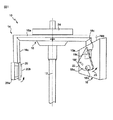
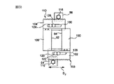
図1に全体を参照番号10で示してあるように、本発明による歯科用放射線装置は、パノラマ撮影タイプの装置である。この装置により、ある対象物(例えば歯列弓)のパノラマ画像を生成させることができる。この装置は、固定されたフレーム12(例えば鉛直な支柱)を備えており、そのフレームに、回転する断層撮影ユニット14が取り付けられている。断層撮影ユニットについてこれから説明する。
As indicated generally by the
このユニットは、横倒しにされたC字形の可動構造体16(アーチ)を備えていて、このアーチは、支持体を形成していてC字の本体を構成する中央の水平な支柱16aと、この水平な支柱から下に向かってそれぞれがC字の2つの枝を構成する鉛直な2本のアーム16b、16cとを有する。
This unit is provided with a C-shaped movable structure 16 (arch) that is laid sideways, and this arch forms a support and forms a C-shaped main body with a central
X線源またはX線発生装置18がアーム16bに固定されている一方で、可動検出ユニット20がアーム16cに取り付けられている。
While the X-ray source or
したがってX線発生装置18と検出ユニット20は互いに向かい合って配置されていて、互いに固定された幾何学的関係にある。
Therefore, the
X線発生装置18と検出ユニット20の支持体として機能する構造体16は、回転するX線撮影ユニット14の心臓部を構成する。
The
放射線医学装置10は、図示していないが、フレーム12の一端に固定された下方アームも備えている。このアームの自由端には、この装置が動作してX線画像を取得している間、患者の頭部を動かなくすることのできる位置決め装置が取り付けられている。したがって頭部はX線発生装置18と検出ユニット20の間に挿入される。
Although not shown, the
X線発生装置18には、検出ユニット20と向かい合う面18aに、例えば円弧の形状(扇形)の可動支持体22が取り付けられている。この面18aには、X線発生装置から出るX線の出力ウインドウ18bが設けられている。
In the
支持体22は、X線のこの出力ウインドウ18bの前に位置しており、複数(例えば3つ)のコリメーション用スリットを備えている。これらスリットは、それぞれ、支持体の制御状態に応じて出力ウインドウ18bの正面に位置する。
The
移動手段(例えばモータ18c)により、支持体22の移動を制御することができる。ここでは移動は、X線発生装置の面18aに垂直な軸18dのまわりを回転する形態でなされる。
The movement of the
図示した例では、スリットは、互いに垂直な方向に延びている。各スリットが順番にウインドウ18bの前に配置されるとき、スリット18eは鉛直方向であり、スリット18fは水平方向である。
In the illustrated example, the slits extend in directions perpendicular to each other. When each slit is arranged in front of the
各スリットは例えば長方形の形状である。 Each slit has, for example, a rectangular shape.
したがってコリメートされたX線ビームは、正面にある長方形断面のスリットを通過することによって先端が切断された円錐の形状を持つ。このビームは、底面において(スリットの面に平行な断面内で)、スリットが延伸する方向に対応する方向に沿って延びている。 Therefore, the collimated X-ray beam has a conical shape in which the tip is cut by passing through a rectangular cross-section slit in front. The beam extends along the direction corresponding to the direction in which the slit extends in the bottom surface (within a cross section parallel to the plane of the slit).
図1に示した状態では、Z軸に沿って延伸するスリット18eが選択された(X線発生装置の第1の動作モード)。
In the state shown in FIG. 1, the
アーム16cに固定されたセンサー20は、X線発生装置18と向かい合った位置にある。このセンサーは、X線発生装置から出てそのX線発生装置とセンサーの間に配置された対象物を照射した後のX線を受光することと、対象物を横断することによって減衰したX線を、この対象物のX線画像を表わす電気信号に変換することができる。
The
センサーは、装置のこの第1の動作モードのため、Z軸(図1)に平行な長手方向に沿って延伸していてコリメーション用スリット18eから出るビームに対応する構成にされた画素マトリックスを備えていることに注意されたい。
For this first mode of operation of the device, the sensor comprises a pixel matrix configured to correspond to the beam extending along the longitudinal direction parallel to the Z axis (FIG. 1) and exiting from the
このセンサーは、例えばCCDタイプの電荷移動センサーであり、その長方形のサイズは例えば12cm(Z軸に沿った高さ)×1cm(幅)である。センサー20aの制御と電力供給のための電子回路が、そのセンサーの裏側に設けられている。
This sensor is, for example, a CCD type charge transfer sensor, and its rectangular size is, for example, 12 cm (height along the Z axis) × 1 cm (width). An electronic circuit for controlling the
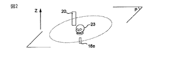
図1の装置は、公知のようにパノラマ撮影モード(第1のモード)で動作することができる。 The apparatus of FIG. 1 can operate in a panoramic shooting mode (first mode) as is well known.
そうするため、第1の形状のスリット22aを備えたX線発生装置とアーチ状構造体によって支持された第1のセンサー20aとを含む組立体が、Z軸に垂直な面P内を移動する(図2)。しかし装置の動作は、互いに垂直なZ軸と面Pがそれぞれ鉛直方向と水平方向でないとしても同じであろう。
To do so, an assembly including an X-ray generator having a first-shaped slit 22a and a
面P内の移動は、Z軸に平行な軸の回転と、患者23の顎の歯列弓の全体形状を再現する馬蹄形の軌跡に沿った移動を組み合わせた結果としての運動である。 The movement in the plane P is a movement resulting from a combination of rotation of an axis parallel to the Z axis and movement along a horseshoe-shaped trajectory that reproduces the overall shape of the dental arch of the patient's 23 jaw.
この軌跡は、水平面内で、歯列弓の互いに反対側の2つの辺の間の平均線に対応している。 This trajectory corresponds to an average line between two opposite sides of the dental arch in the horizontal plane.
X線発生装置−センサーの組立体の移動は、支持構造体の移動手段によって保証される。 Movement of the X-ray generator-sensor assembly is ensured by means of movement of the support structure.
この手段は、例えばX、Y方向に制御される移動盤の形態(サーボ制御機構)であり、上記の軌跡を描くようプログラムされている。 This means is, for example, in the form of a moving board (servo control mechanism) controlled in the X and Y directions, and is programmed to draw the trajectory.
図3に非常に大まかに示してあるように、盤24は、第1の方向A1(Y)を向いた長手方向の2本のレール32、34の上を第1の駆動手段の作用によって滑る第1の台車30を備えている。第1の駆動手段は、例えばウォーム38によってその台車に接続されたモータ36である。
As shown very roughly in FIG. 3, the
盤は、第2の方向A2(X)(方向A1とA2は、面Pに平行な平面内に含まれる)の長手方向を向いた2本のレール42、44の上を第2の駆動手段の作用によって滑る第2の台車40も備えている。第2の駆動手段は、例えばウォーム48によってその台車に接続されたモータ46である。
The board is a second drive means on the two
盤24はアーチ形状の構造体16と一体化しており、駆動手段49(例えばモータ)が構造体16に接続されていて、命令により、この構造体を、面Pに垂直で、したがって方向A1とA2によって規定される面に垂直な回転軸51のまわりに回転駆動する。
The
台車30と40がX方向とY方向に沿って移動するのを適切に制御することにより、構造体16は、面P内で求める(馬蹄形の)軌跡を描く。
By appropriately controlling the movement of the
X線発生装置と第1のセンサー20aが面P内で対象物(患者の顎)のまわりを移動するとき、そのセンサーは、TDI(時間遅延積分として知られる)と呼ばれるモードで動作する。
When the X-ray generator and the
公知のこの動作モードは、患者の顎を照射したX線を捕集する可動センサーの画素が顎に対して固定されていると見なされるようにすることを目的としている。 This known mode of operation is intended to ensure that the pixels of the movable sensor that collects the X-rays irradiating the patient's jaw are considered fixed relative to the jaw.
そうするため、マトリックスの読み取りパルスのもとで、シフト・レジスタに向けてのマトリックスの行のシフトがセンサーの移動方向と逆になるように画素マトリックスの読み取り頻度を調節する。 To do so, the pixel matrix read frequency is adjusted under the matrix read pulse so that the shift of the matrix row towards the shift register is opposite to the direction of movement of the sensor.
したがってTDIモードにより、得られるパノラマ画像のぼけ現象を避けることができる。 Therefore, the blurring phenomenon of the obtained panoramic image can be avoided by the TDI mode.
図1の装置に関して上に説明したばかりの第1の動作モードは、パノラマ撮影モードに関する。 The first operating mode just described above with respect to the apparatus of FIG. 1 relates to the panoramic shooting mode.
しかし本発明の装置を第2の動作モードで利用し、パノラマ撮影動作モードにおいてセンサーとX線発生装置がたどることになる軌跡を決定することができる。 However, by using the apparatus of the present invention in the second operation mode, it is possible to determine the trajectory that the sensor and the X-ray generator follow in the panoramic imaging operation mode.
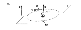
そうするため、装置は、図2のセンサー20を90°軸回転させてそのセンサーを図4に示した位置にする手段20b(例えばモータ)を備えている。
To do so, the apparatus includes
するとセンサーは面Pに平行な方向に沿って延びた状態に配置される。 Then, a sensor is arrange | positioned in the state extended along the direction parallel to the surface P. FIG.
装置は、一般に少なくとも1つのコリメーション用スリット(図2でZ軸に沿って延伸するスリット)を有するX線発生装置が、第1の動作モードから、スリットが面Pとセンサーの長手方向に平行な方向に沿って延びている第2の動作モードへと移行するのに適した手段をさらに備えている。 The apparatus is generally an X-ray generator having at least one collimation slit (slit extending along the Z-axis in FIG. 2) from the first mode of operation where the slit is parallel to the plane P and the longitudinal direction of the sensor. There is further provided means suitable for transitioning to a second mode of operation extending along the direction.
第2の動作モードでは、このような空間的方向のスリットを有するX線発生装置は、底面においてその同じ方向に沿って延伸するX線ビームを生成させることができる。 In the second mode of operation, an X-ray generator having such spatial slits can generate an X-ray beam that extends along the same direction at the bottom surface.
したがってセンサーとスリットは常に向かい合った位置にあるため、X線ビームは軸回転した後に常にセンサーに到達することができる。 Therefore, since the sensor and the slit are always in a position facing each other, the X-ray beam can always reach the sensor after rotating the axis.
図1に示した実施例では、放射線医学装置は、スリットの支持体22の駆動手段18cに対する移動命令に従って切り換えることのできる2つのコリメーション用スリット18e、18fを備えている。
In the embodiment shown in FIG. 1, the radiology apparatus comprises two
スリットを切り換える(スリット支持体を矢印25で示した方向に軸回転させる)ことにより、図2の鉛直方向のスリット18eは水平方向のスリット18fで置き換えられ、そのスリット18fが出力ウインドウ18bの前に来る。
By switching the slits (rotating the slit support in the direction indicated by the arrow 25), the
このように配置されたセンサー20とスリット18f(図4)は、次に、対象物23に合った上記の軌跡を決定するため、図3の手段49によって回転軸B(鉛直方向)のまわりに回転駆動される。軌跡の決定についてはあとで説明する。
The
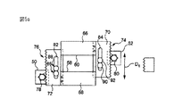
図5aと図5bは、図1のスリット18eと18fの代わりに、幾何学的形状を変えることのできる単一のコリメーション用スリットを実現できる一変形例を示している。
FIGS. 5a and 5b show a variation in which a single collimation slit with a changeable geometric shape can be realized instead of the
命令によってスリットの幾何学的形状を変えるため、その中でも特に互いに垂直な2つの方向(例えば水平方向と鉛直方向)に沿った長さを変えるため、調節手段が設けられている。 In order to change the geometric shape of the slit according to the command, an adjusting means is provided in order to change the length along two directions perpendicular to each other (for example, the horizontal direction and the vertical direction).
より詳細には、スリットの1つの方向に沿った長さを変えることのできる調節手段は、別の方向での長さを変えることのできる手段とは独立であるため、調節の柔軟性が非常に大きい。 More specifically, the adjustment means that can change the length along one direction of the slit is independent of the means that can change the length in another direction, so the flexibility of adjustment is very high. Big.
図示した実施例では、放射線医学装置は、コリメーション用スリットを規定する4つの辺58、60、62、64のそれぞれの位置を独立に変化させる独立な4つの調節手段50、52、54、56を備えている。
In the illustrated embodiment, the radiology device comprises four independent adjustment means 50, 52, 54, 56 that independently change the position of each of the four
この装置は、例えば図1のX線発生装置に支持されるか、構造体16(例えばアーム16b)に直接固定されてウインドウ18bの前に位置するスリット支持体(図示せず)を備えている。
This apparatus includes, for example, a slit support (not shown) that is supported by the X-ray generator of FIG. 1 or directly fixed to the structure 16 (for example, the
この支持体には、順番に、図5bの機構が、次いで図5aの機構が重ねられる。 This support is in turn overlaid with the mechanism of FIG. 5b and then the mechanism of FIG. 5a.
これらの機構は、図を見やすくするために重ねた状態では示していない。 These mechanisms are not shown in a stacked state for the sake of clarity.
より詳細には、図5aの機構は、互いに向かい合って配置された2枚の(例えば長方形の)プレート66、68の2つの辺58、60を備えており、それぞれ、垂直に配置された別のプレート70、72に固定されている。
More specifically, the mechanism of FIG. 5a comprises two
したがってそれぞれのプレート対66、70と68、72は、L字、または180°回転したL字を形成する。
Thus, each
それぞれの対の第2のプレート70、72は、第1のプレートが固定されている辺とは反対側の辺に、一列になった長手方向の歯74、76を備えている。
Each pair of
辺58(または60)の移動手段は、歯の付いたピニオン78(または80)を出力軸に有するモータ50(または52)を備えている。このピニオンは、歯76(または74)と協働し、ピニオンの回転方向に応じてプレート72と68を方向D1に沿っていずれかの方向に移動させる。
The moving means of the side 58 (or 60) includes a motor 50 (or 52) having a toothed pinion 78 (or 80) as an output shaft. This pinion cooperates with the teeth 76 (or 74) and moves the
対応するプレート、したがって対応する辺の長手方向の移動をガイドするため、ガイド用開口部82(または84)が第2のプレート72(または70)に設けられるとともに、上記の支持体に固定された2つのガイド用ピン86、88(または90、92)がこの開口部の中に位置している。 A guide opening 82 (or 84) is provided in the second plate 72 (or 70) and is fixed to the support to guide the longitudinal movement of the corresponding plate and thus the corresponding side. Two guide pins 86, 88 (or 90, 92) are located in this opening.
この機構によって向かい合った辺58と60の方向D1に沿った離れ具合を調節することで、スリットの1つの方向のサイズ、したがって1つの方向の長さを調節することができる。
By adjusting the distance along the direction D1 between the opposing
それと同様に、図5bに示した機構によって向かい合った辺62と64の垂直な方向D2に沿った離れ具合を調節することで、別の方向に沿ったスリットの1つのサイズを調節することができる。
Similarly, by adjusting the distance along the vertical direction D2 of the
例えば辺62と64を近づけ、辺58と60を離すと、方向D1に沿って細長い形状のスリットになる。すると(図1と図2のスリット18eと同様)図5cに示したZ軸に沿って細長いスリットが得られる。
For example, when the
逆に、辺62と64を離し、辺58と60を近づけると、方向D2に沿って細長い形状のスリットが実現する。したがって図1と図4のスリット18fのようにZ軸に垂直な軸に沿って細長いスリットが得られる。
Conversely, when the
図5bに示したさまざまな要素、すなわち第1と第2のプレート100、102(または104、106)、歯108(または110)、モータ54(または56)、歯の付いたピニオン116(または118)、ガイド用開口部128(または130)の中のガイド用ピン120、122(または124、126)は、図6aの対応する要素と同じだが、90°だけずれている。
The various elements shown in FIG. 5b: first and
上に説明したばかりのパノラマ撮影装置10は、従来よりも品質が向上したパノラマ画像の実現を可能にする手段を備えている。この装置の利用法/動作モードについてこれから説明する。
The
図6は、本発明の装置10を動作させる方法の主要なステップを詳細に示すアルゴリズムである。
FIG. 6 is an algorithm detailing the main steps of the method of operating the
このアルゴリズムは、例えば装置10の機能を制御するプログラム可能な装置(例えばPCタイプのコンピュータ)のメモリ領域に記憶され、命令によって実行される。
This algorithm is stored, for example, in a memory area of a programmable device (for example, a PC type computer) that controls the function of the
本発明の方法は、自動的に実施できると望ましかろう。すると人間の介入が制限される。 It would be desirable to be able to perform the method of the present invention automatically. This limits human intervention.
図6に示した本発明の方法のアルゴリズムは、放射線医学装置がパノラマ撮影モード(第1の動作モード)から出て軸回転モード(第2の動作モード)に移る第1のステップS1を含んでいる。 The algorithm of the method of the present invention shown in FIG. 6 includes a first step S1 in which the radiology apparatus exits the panoramic imaging mode (first operation mode) and moves to the axis rotation mode (second operation mode). Yes.
より詳細には、このステップにおいて、センサーはモータ20bによって自動的に回転駆動され、装置がパノラマ撮影モードで動作するとき(図1と図2)に占める初期位置から90°軸回転運動する。
More specifically, in this step, the sensor is automatically driven to rotate by the
このときセンサーは、面Pに平行な方向に沿って延伸する配置にされている(図4)。同様に、X線発生装置の第2の動作モードでは、スリット支持体22が移動してスリット18fがウインドウ18bの前に来る。したがって面Pおよびセンサーと平行な方向を向いたこのスリットによってコリメートされたX線ビームは、センサーの新しい位置に常に対応するようになっている。したがってX線発生装置から出てスリットによってコリメートされたX線は、向かい合ったセンサーによって常に受光される。
At this time, the sensor is arranged to extend along a direction parallel to the surface P (FIG. 4). Similarly, in the second operation mode of the X-ray generator, the
図5aと図5bに示した変形例だと、上に説明したように適切なやり方で辺を移動させて調節可能なスリットを変形させ、図2(図5c)のスリットから図4のスリットに移すことに注意されたい。 In the modification shown in FIGS. 5a and 5b, the adjustable slit is deformed by moving the sides in an appropriate manner as described above, from the slit of FIG. 2 (FIG. 5c) to the slit of FIG. Please note that it is transferred.
次のステップS2では、放射線医学装置がCBCT(コーン・ビーム断層撮影)動作モードに移る。 In the next step S2, the radiology apparatus moves to a CBCT (cone beam tomography) operation mode.
パノラマ撮影装置は、CBCT技術の画像センサーが不適切な形状であるため、通常は、CBCT技術でX線撮影を行なう装備を備えていないことに注意されたい。 It should be noted that a panoramic imaging apparatus usually does not include equipment for performing X-ray imaging with the CBCT technology because the image sensor of the CBCT technology has an inappropriate shape.
しかし本発明では、この技術を利用して完全なX線画像を得ることはできず、この動作モードは、一時的に、パノラマ撮影モードではアクセスできない(照射された対象物に固有の)個人的ないくつかのデータを取得するのに用いられる。このデータは、のちにパノラマ撮影モードで利用されることになる。 However, in the present invention, this technique cannot be used to obtain a complete X-ray image, and this mode of operation is temporarily inaccessible in the panoramic imaging mode (individually specific to the illuminated object). It is used to acquire some data. This data will be used later in the panoramic shooting mode.
したがってステップS2の後に、X線発生装置とセンサーの間に配置された対象物(例えば図4の対象物23、より詳細には患者の顎)のデータをコーン・ビーム断層撮影(CBCT)モードで取得するステップS3が続く。
Therefore, after step S2, data of an object (eg, the
特にステップS3においては、コリメーション用スリットを有するX線発生装置とセンサーからなる組立体が面P内でZ軸に平行な軸Bのまわりに回転駆動される。この回転運動の間、この組立体は、順番に複数の角度位置を占め、その各角度位置において、コリメートされたX線を照射された対象物の画像信号がセンサーによって取得される。 In particular, in step S3, an assembly composed of an X-ray generator having a collimation slit and a sensor is rotated around an axis B parallel to the Z axis in the plane P. During this rotational movement, the assembly occupies a plurality of angular positions in turn, and at each angular position, an image signal of an object irradiated with collimated X-rays is acquired by a sensor.
この運動の間、X線発生装置−センサーの組立体の回転中心は固定されている。この中心は、例えば対象物23の上に位置する。
During this movement, the center of rotation of the X-ray generator-sensor assembly is fixed. This center is located on the
この組立体の各角度位置に関してセンサーによって捕集されたデータは、対象物の、X線発生装置−画像センサーの軸に沿った射影を表わす。 The data collected by the sensor for each angular position of the assembly represents the projection of the object along the X-ray generator-image sensor axis.
したがってX線発生装置とセンサーの組立体が完全に一回転し終わると、例えば、ビームを照射された対象物23の1つの射影をそれぞれが表わす画像信号の集合と、対象物の360通りの射影(1°回転するごとに撮影される場合)が得られる。
Therefore, when the assembly of the X-ray generator and the sensor is completed one complete rotation, for example, a set of image signals each representing one projection of the
それぞれのアナログ画像信号は、センサーの画素マトリックスによって捕集され、そのセンサーによってアナログ電気信号に変換され、次いでディジタル信号に変換される。 Each analog image signal is collected by the sensor's pixel matrix, converted to an analog electrical signal by the sensor, and then converted to a digital signal.
これらの信号を得るのに用いるX線の線量を減らすには、読み取りのためにセンサーがマトリックスの画素をあらかじめ決めた数(例えば2または3)に従ってグループ化できることを利用するのが適切であることに注意されたい。
To reduce the dose of X-rays used to obtain these signals, it is appropriate to take advantage of the fact that the sensor can group matrix pixels according to a predetermined number (
確かに、選択したグループ化に従って画素を2つまたは3つのグループによって読み取ることにより、マトリックスの読み取りの雑音が減ってセンサーの信号対雑音比が大きくなるため、X線の線量を少なくすることができる。 Indeed, reading the pixels by two or three groups according to the selected grouping can reduce the dose of X-rays because the noise of the matrix reading is reduced and the sensor signal-to-noise ratio is increased. .
次のステップS4では、対象物の照射された部分の立体が、あらかじめ得られた画像信号の集合をもとにして再構成される。再構成されたこの立体は、高さが低い円柱150の形状である。倍率は別にして、この円柱の高さまたは厚さz1は、センサーの最も短い部分の長さ(短辺)に対応しているのに対し、この円柱の直径のほうは、センサーの最も長い部分の長さ(長辺)によって制限される。
In the next step S4, the solid of the irradiated part of the object is reconstructed based on a set of image signals obtained in advance. This reconstructed solid is in the shape of a
例えば円柱の高さは、数ミクロンから数ミリメートルになる。 For example, the height of the cylinder is several microns to several millimeters.
立体150を図7に示してある。この立体は、患者の歯列弓を包含している。 A solid 150 is shown in FIG. This solid contains the patient's dental arch.
再構成されたこの立体150は、照射された対象物の形状の立体表示を提供する。この立体には、この対象物に特有の求めるデータを明らかにするのに十分な情報が含まれる。 This reconstructed solid 150 provides a three-dimensional display of the shape of the illuminated object. This solid contains enough information to reveal the desired data specific to this object.
対象物の立体表示は、興味の対象である領域の(軸Zに沿った)高さの中心に位置することに注意されたい。このように中心を決める操作は、X線発生装置−センサーの組立体を、その組立体を回転させる前に位置決めするとき(ステップS2)に実現される。ここで説明している例において興味の対象となる領域は、患者の顎の“噛み合わせ面”、すなわち歯と歯の接触面である。 Note that the stereoscopic display of the object is located at the center of the height (along axis Z) of the region of interest. The operation of determining the center as described above is realized when the X-ray generator-sensor assembly is positioned before the assembly is rotated (step S2). In the example described here, the area of interest is the “mating surface” of the patient's jaw, ie the tooth-to-tooth contact surface.
次のステップS5では、このようにして再構成された立体から、興味の対象である対象物またはその一部を、すなわち特にここでは患者の歯列弓を明確にする。 In the next step S5, the object of interest or part of it, ie in particular here the patient's dental arch, is clarified from the solid thus reconstructed.
そのためには、再構成された立体中のデータに対して“閾値化”または“セグメント化”と呼ばれる操作を行なう。 For this purpose, an operation called “thresholding” or “segmentation” is performed on the data in the reconstructed solid.
例えば閾値化によって歯とその周辺環境の間で密度の差を表わすグレーのレベルの差を分析することで、歯列弓の三次元形状を導出する。 For example, the three-dimensional shape of the dental arch is derived by analyzing the difference in gray level representing the difference in density between the tooth and the surrounding environment by thresholding.
歯列弓152の形状がこのようにして得られる。それを上から見た図として図8に示してある。この図では、再構成された立体150の包絡線も示してある。
The shape of the
歯列弓152の形状から水平断面を取り出すことにより、次のステップS6において、上から見たときに歯列弓の中でその歯列弓の互いに向かい合った辺の間を延伸する平均線154を決定する。
By taking a horizontal cross section from the shape of the
この平均線の決定は、“軌跡”を特定することに対応する。 This determination of the average line corresponds to specifying the “trajectory”.
より詳細には、この平均線154(図8)は、のちに装置がパノラマ撮影モードで動作するとき、X線発生装置とセンサーが対象物のパノラマ画像を得るためにたどる軌跡として利用されることになる。 More specifically, this average line 154 (FIG. 8) is used as a trajectory that the X-ray generator and sensor follow to obtain a panoramic image of the object when the apparatus is later operated in a panoramic imaging mode. become.
馬蹄形のこの軌跡により、対象物に適合していて個人に合わせた状態で、パノラマ撮影装置10をプログラムすることができる。従来のパノラマ撮影装置は、標準的な歯列弓の形状をもとにして機能する。したがってその歯列弓はX線撮影する対象物に合っておらず、本発明とは異なってほとんど正確ではない。
With this horseshoe-shaped trajectory, the
閾値化のステップは、軌跡の決定の一部をなすことに注意されたい。 Note that the thresholding step is part of the trajectory determination.
ステップS6で特定される軌跡は、さまざまな現象(歯の充填物などの金属アーチファクト(金属対象物の周囲に星状のノイズを生じさせる可能性がある)や、場の中に存在する他の対象物(例えば図8の脊柱156))によって乱されることがある。
The trajectory identified in step S6 can be a variety of phenomena (metal artifacts such as tooth filling (which can cause star-like noise around the metal object) and other phenomena present in the field. It may be disturbed by an object (eg,
ステップS6で得られた軌跡の精度を向上させるため、この軌跡を例えば平滑化によって修正する(オプションの)ステップS7が設けられている。 In order to improve the accuracy of the trajectory obtained in step S6, an optional step S7 is provided for correcting the trajectory, for example by smoothing.
修正された軌跡が得られると、次のステップS8に移る。このステップでは、スリットは新たに90°軸回転し、Z軸(ここでは鉛直軸)に平行な向きに戻される。 When the corrected trajectory is obtained, the process proceeds to the next step S8. In this step, the slit is newly rotated by 90 ° and returned to a direction parallel to the Z axis (here, the vertical axis).
同様に、スリット支持体22を移動させてスリット18eをX線発生装置のウインドウ18bの前に来させると、X線発生装置は第1の動作モードに戻る。センサーとX線発生装置のスリットのこの配置は、すでに説明した図2の配置である。
Similarly, when the
軸まわりのこの回転ステップの後、パノラマ撮影装置を新たにプログラムしてパノラマ撮影モードで動作させることができる。 After this rotation step about the axis, the panoramic imager can be newly programmed and operated in the panoramic mode.
この機会に、ステップS6で得られて場合によってはステップS7で変更された軌跡が利用され、コリメーション用スリットを有するX線発生装置とセンサーとが新たにZ軸に平行に配置された状態の組立体の移動がプログラムされる。 On this occasion, the trajectory obtained in step S6 and possibly changed in step S7 is used, and the X-ray generator and sensor having a collimation slit are newly arranged in parallel to the Z axis. Solid movement is programmed.
従来よりも合致した軌跡を利用して装置がパノラマ撮影モードで動作している間、X線発生装置とセンサーからなる組立体は、鉛直方向の回転軸のまわりを回転運動する。この回転軸は、命令を受け、図3に示したさまざまな駆動手段のおかげでこの軌跡に沿った移動もする。 While the apparatus operates in the panoramic imaging mode using a locus that is more consistent than the conventional one, the assembly including the X-ray generator and the sensor rotates around the vertical rotation axis. The axis of rotation also receives commands and moves along this trajectory thanks to the various drive means shown in FIG.
この移動の間、鉛直方向に配置されたセンサーは、上に説明したTDIモードで動作し、X線を照射された対象物(ここでは歯列弓)の画像データを取得する。その画像データから、求めるパノラマ画像が生成される。 During this movement, the sensor arranged in the vertical direction operates in the TDI mode described above, and acquires image data of an object (here, a dental arch) irradiated with X-rays. A desired panoramic image is generated from the image data.
公知のように、歯列弓のパノラマ画像は、馬蹄形の軌跡に沿って移動している間にセンサーによって取得された画像データをもとにして得られる。 As is well known, a panoramic image of a dental arch is obtained based on image data acquired by a sensor while moving along a horseshoe-shaped trajectory.
アーチ16の回転運動と、移動盤24の助けを借りたアーチの回転中心の移動と、センサーの画素のシフト(TDIモード)とを組み合わせることにより、鮮明領域の中に常に含まれる仮想的な回転点を再び作り出す。したがって鮮明領域の外に位置する解剖学的構造体は引きずりによるぼけとなって診断を損なうことはないのに対し、鮮明領域に含まれる構造体は鮮明に現われる。
By combining the rotational movement of the arch 16, the movement of the rotational center of the arch with the help of the moving
図9は、本発明によって得られたパノラマ画像の概略図である。 FIG. 9 is a schematic view of a panoramic image obtained by the present invention.
このようにして得られたパノラマ画像は、従来から知られている方法と比べて最適化された品質を持つことに注意されたい。というのも、パノラマ画像は、ここでは、対象物、特にこの場合には患者の顎の形状に完全に合っているからである。 It should be noted that the panoramic image obtained in this way has an optimized quality compared to the methods known in the art. This is because the panoramic image here perfectly matches the shape of the object, in this case the patient's jaw.
さらに、上に説明したばかりの方法では、オペレータが、不正確な結果をもたらす多数の操作をすることが回避される。 Furthermore, the method just described avoids the operator from performing many operations that yield inaccurate results.
装置がCBCTモードで動作しているとき、このモードでは高品質の画像を得ようとしていないことに注意されたい。それが理由で、この動作モードではX線の線量を減らすことができる。 Note that when the device is operating in CBCT mode, it is not trying to obtain high quality images in this mode. For this reason, the X-ray dose can be reduced in this mode of operation.
Claims (14)
X線発生装置(18)と、その正面にあってそのX線発生装置から出るX線を受光するセンサー(20)とを備えていて、そのX線発生装置とそのセンサーで構成される組立体をある面(P)内の所定の軌跡に沿って移動させることによって対象物のパノラマ画像を生成させることができるもので、
X線発生装置は、面(P)に垂直な軸(Z)に沿って延伸する少なくとも1つのコリメーション用スリット(18e、18f)を備えていて、
第1の動作モードにおいて、この軸に沿って延伸するX線ビームを発生させ、
センサーは画素マトリックスを備えていて、このビームに対応して軸(Z)に沿って延伸する構成にされているものにおいて、
センサーを90°軸回転させて面(P)に平行な方向に延伸するようにする手段と、
少なくとも1つのコリメーション用スリット(18e、18f)を備えるX線発生装置を第1の動作モードから第2の動作モードに移行させ、その第2の動作モードにおいて、センサーの方向に平行に延伸するX線ビームを発生させることで、このように配置されたセンサーがそのビームと常に対応しているようにする手段(22)とを備える、
ことを特徴とする歯科用放射線装置。 A dental radiation device (10) comprising:
An X-ray generator (18) and a sensor (20) for receiving X-rays emitted from the X-ray generator in front of the X-ray generator, and an assembly comprising the X-ray generator and the sensor Can be generated along a predetermined trajectory in a certain plane (P) to generate a panoramic image of the object.
The X-ray generator comprises at least one collimation slit (18e, 18f) extending along an axis (Z) perpendicular to the plane (P),
In a first mode of operation, generating an X-ray beam extending along this axis;
The sensor includes a pixel matrix and is configured to extend along the axis (Z) corresponding to the beam.
Means for rotating the sensor by 90 ° and extending in a direction parallel to the plane (P);
An X-ray generator having at least one collimation slit (18e, 18f) is shifted from the first operation mode to the second operation mode, and in the second operation mode, X extends parallel to the direction of the sensor. Means (22) for generating a line beam so that the sensor arranged in this way always corresponds to the beam;
A dental radiation apparatus characterized by that.
その回転運動の間にX線発生装置−センサーの組立体が取る複数の角度位置について、コリメートされたX線を照射された対象物の複数の画像信号を取得する手段と、
取得した画像信号の集合をもとにして、照射された対象物の立体表示を得る手段と、
このようにして得られた立体表示をもとにして、その対象物のパノラマ画像をのちに生成させるときにX線発生装置−センサーの組立体がたどらねばならない軌跡を特定する手段と、を備える、
ことを特徴とする請求項1に記載の歯科用放射線装置。 Means for rotationally driving an assembly composed of the X-ray generator in the second operation mode and a sensor arranged in parallel with the plane (P) around a fixed axis parallel to the axis (Z) ( 49),
Means for acquiring a plurality of image signals of an object irradiated with collimated X-rays for a plurality of angular positions taken by the X-ray generator-sensor assembly during its rotational movement;
Means for obtaining a three-dimensional display of the irradiated object based on the acquired set of image signals;
Means for identifying a trajectory that the X-ray generator-sensor assembly must follow when a panoramic image of the object is to be generated later on the basis of the stereoscopic display thus obtained. ,
The dental radiation apparatus according to claim 1.
その読み取り手段が、所定数の画素に従って画素をグループ化する手段を備えているため、このようにグループ化された画素が読み取られる、
ことを特徴とする請求項2に記載の歯科用放射線装置。 Means for acquiring a plurality of image signals comprises means for reading data collected by the pixel matrix of the sensor;
Since the reading means includes means for grouping pixels according to a predetermined number of pixels, the pixels grouped in this way are read.
The dental radiation apparatus according to claim 2, wherein:
ことを特徴とする、請求項2または3に記載の歯科用放射線装置。 The means for specifying the trajectory based on the obtained stereoscopic display includes means for thresholding or segmenting data constituting the stereoscopic display.
The dental radiation apparatus according to claim 2, wherein the dental radiation apparatus is characterized in that
ことを特徴とする請求項1から4のいずれか1項に記載の歯科用放射線装置。 Since the X-ray generator (18) includes a single collimation slit, the X-ray generator and the slit are rotated along the direction parallel to the plane (P) by rotating the slit by 90 °. A line beam can be generated,
The dental radiation apparatus according to any one of claims 1 to 4, wherein the dental radiation apparatus is characterized in that
ことを特徴とする請求項1から4のいずれか1項に記載の歯科用放射線装置。 Since the X-ray generator is provided with two collimation slits (18e, 18f) extending along directions perpendicular to each other, each passes in front of the X-ray generator one after another according to a command. An X-ray beam extending along (Z) and an X-ray beam extending along an axis perpendicular to the axis (Z) can be generated, respectively.
The dental radiation apparatus according to any one of claims 1 to 4, wherein the dental radiation apparatus is characterized in that
ことを特徴とする請求項1から4のいずれか1項に記載の歯科用放射線装置。 The X-ray generator (18) comprises a single collimation slit, and the dental radiology device adjusts the lengths (74, 76, 78, 80) of the slits in the direction perpendicular to each other. , 108, 110, 116, 118),
The dental radiation apparatus according to any one of claims 1 to 4, wherein the dental radiation apparatus is characterized in that
歯科用放射線装置が、
X線発生装置(18)と、その正面にあってそのX線発生装置から出るX線を受光するセンサー(20)とを備えていて、
そのX線発生装置は、面(P)に垂直な軸(Z)に沿って延伸する少なくとも1つのコリメーション用スリット(18e、18f)を備えていて、第1の動作モードにおいて、この軸に沿って延伸するX線ビームを発生させ、センサーは画素マトリックスを備えていて、このビームに対応して軸(Z)に沿って延伸する構成にされていて、
この方法が、
その対象物のパノラマ画像を生成させるためにX線発生装置−センサーの組立体が面(P)内をたどる軌跡を得るため、この歯科用放射線装置をコーン・ビーム断層撮影モードで動作させることを目的として、
センサーを90°軸回転させて面(P)に平行な方向に延伸するようにするステップ(S1)と、
少なくとも1つのコリメーション用スリット(18e、18f)を備えるX線発生装置を第1の動作モードから第2の動作モードに移行させ、その第2の動作モードにおいて、センサーの方向に平行に延伸するX線ビームを発生させることで、このように配置されたセンサーがそのビームと常に対応しているようにするステップ(S2)と、
をあらかじめ含む、
ことを特徴とする方法。 A method for generating a panoramic image of an object based on a dental radiation apparatus,
Dental radiology equipment
An X-ray generator (18), and a sensor (20) for receiving X-rays emitted from the X-ray generator in front of the X-ray generator;
The X-ray generator comprises at least one collimation slit (18e, 18f) extending along an axis (Z) perpendicular to the plane (P), and along this axis in the first mode of operation. Generating an X-ray beam that extends, and the sensor includes a pixel matrix and is configured to extend along an axis (Z) corresponding to the beam,
This method
In order to obtain a trajectory that the X-ray generator-sensor assembly follows in the plane (P) in order to generate a panoramic image of the object, the dental radiation apparatus is operated in cone beam tomography mode. as a goal,
Rotating the sensor 90 ° axis to extend in a direction parallel to the plane (P) (S1);
An X-ray generator having at least one collimation slit (18e, 18f) is shifted from the first operation mode to the second operation mode, and in the second operation mode, X extends parallel to the direction of the sensor. Generating a line beam so that the sensor arranged in this way always corresponds to the beam (S2);
Including in advance,
A method characterized by that.
その回転運動の間にX線発生装置−センサーの組立体が取る複数の角度位置について、コリメートされたX線を照射された対象物の複数の画像信号を取得するステップ(S3)と、
取得した画像信号の集合をもとにして、照射された対象物の立体表示を得るステップ(S4)と、
このようにして得られた立体表示をもとにして、その対象物のパノラマ画像をのちに生成させるときにX線発生装置−センサーの組立体がたどらねばならない軌跡を特定するステップ(S6)と、を含む、
ことを特徴とする請求項10に記載の方法。 Rotationally driving an assembly composed of the X-ray generator in the second operation mode and a sensor arranged parallel to the plane (P) around a fixed axis parallel to the axis (Z); ,
Obtaining a plurality of image signals of an object irradiated with collimated X-rays for a plurality of angular positions taken by the X-ray generator-sensor assembly during the rotational movement (S3);
Obtaining a three-dimensional display of the irradiated object based on the acquired set of image signals (S4);
Based on the stereoscopic display obtained in this way, a step (S6) of identifying a trajectory that the X-ray generator-sensor assembly must follow when a panoramic image of the object is to be generated later. ,including,
The method according to claim 10.
ことを特徴とする請求項11に記載の方法。 Acquiring the plurality of image signals includes reading data collected by the pixel matrix of the sensor, and the reading step includes an operation of grouping the pixels according to a predetermined number of pixels; The pixels grouped in this way are read,
The method according to claim 11.
ことを特徴とする請求項11または12に記載の方法。 The step of identifying the trajectory based on the obtained stereoscopic display includes a step of thresholding or segmenting data constituting the stereoscopic display (S5).
The method according to claim 11 or 12, characterized in that:
少なくとも1つのコリメーション用スリットを有するX線発生装置を第2の動作モードから第1の動作モードに移行させるステップと、
少なくとも1つのコリメーション用スリットを有するX線発生装置と、軸(Z)に平行に配置されたスリットとで構成される組立体を、あらかじめ特定された軌跡に沿って移動させる命令を、軸(Z)に平行な軸のまわりの回転運動と組み合わせるステップと、
命令されたこの移動をセンサーの画素のシフトと組み合わせてパノラマ画像を取得するステップと、を含む、
ことを特徴とする請求項11から13のいずれか1項に記載の方法。 Rotating the sensor 90 degrees to return the sensor to a position parallel to the axis (Z) (S8);
Transitioning the X-ray generator having at least one collimation slit from the second operation mode to the first operation mode;
A command for moving an assembly composed of an X-ray generator having at least one collimation slit and a slit arranged in parallel to the axis (Z) along a predetermined trajectory is given to the axis (Z Combined with rotational movement about an axis parallel to
Combining this commanded movement with a shift of the pixel of the sensor to obtain a panoramic image;
14. A method according to any one of claims 11 to 13, characterized in that
Applications Claiming Priority (2)
| Application Number | Priority Date | Filing Date | Title |
|---|---|---|---|
| FR0855685A FR2938183B1 (en) | 2008-08-22 | 2008-08-22 | PANORAMIC DENTAL RADIOLOGY APPARATUS AND METHOD OF USE THEREOF |
| FR0855685 | 2008-08-22 |
Publications (2)
| Publication Number | Publication Date |
|---|---|
| JP2010046486A true JP2010046486A (en) | 2010-03-04 |
| JP5547443B2 JP5547443B2 (en) | 2014-07-16 |
Family
ID=40419086
Family Applications (1)
| Application Number | Title | Priority Date | Filing Date |
|---|---|---|---|
| JP2009193280A Expired - Fee Related JP5547443B2 (en) | 2008-08-22 | 2009-08-24 | Dental radiation device and its use |
Country Status (5)
| Country | Link |
|---|---|
| US (1) | US8503604B2 (en) |
| EP (1) | EP2156792B1 (en) |
| JP (1) | JP5547443B2 (en) |
| KR (1) | KR101642987B1 (en) |
| FR (1) | FR2938183B1 (en) |
Cited By (5)
| Publication number | Priority date | Publication date | Assignee | Title |
|---|---|---|---|---|
| JP2012065779A (en) * | 2010-09-22 | 2012-04-05 | Asahi Roentgen Kogyo Kk | Medical radiography device |
| JP2013116318A (en) * | 2011-11-02 | 2013-06-13 | Morita Mfg Co Ltd | Panoramic tomography x-ray apparatus and image processing device |
| JP2015516825A (en) * | 2012-03-12 | 2015-06-18 | ジェノレイ カンパニー、リミテッド | X-ray equipment |
| WO2016018002A1 (en) * | 2014-07-28 | 2016-02-04 | 주식회사바텍 | X-ray imaging device and x-ray imaging method |
| JP2018532482A (en) * | 2015-10-09 | 2018-11-08 | コーニンクレッカ フィリップス エヌ ヴェKoninklijke Philips N.V. | Advanced control functions for steering devices for intravascular devices and related systems and methods |
Families Citing this family (16)
| Publication number | Priority date | Publication date | Assignee | Title |
|---|---|---|---|---|
| CN103458793B (en) * | 2010-12-22 | 2018-08-03 | 特罗菲公司 | Digital detector |
| FR2982759B1 (en) | 2011-11-17 | 2013-11-29 | Trophy | PANORAMIC DENTAL RADIOLOGY APPARATUS |
| FR2992877B1 (en) * | 2012-07-06 | 2015-07-03 | Phenix Systems | LASER BEAM DRIVING METHOD FOR MANUFACTURING THREE DIMENSIONAL OBJECTS WITH SUPERIMPOSED LAYERS. |
| JP6370297B2 (en) * | 2012-09-07 | 2018-08-08 | トロフィー | Device for partial CT imaging |
| KR20150088679A (en) * | 2014-01-24 | 2015-08-03 | 주식회사바텍 | Apparatus for Obtaining Computed Tomography |
| US9730656B2 (en) | 2014-03-07 | 2017-08-15 | Elwha Llc | Systems, devices, and methods for lowering dental x-ray dosage including feedback sensors |
| CN103908288B (en) * | 2014-03-21 | 2016-03-02 | 北京工业大学 | Along the digitized dentistry surface fault panoramic X-ray machine of true dental arch track scanning |
| US9888891B2 (en) | 2014-06-26 | 2018-02-13 | Palodex Group Oy | X-ray imaging unit for medical imaging |
| CN105741239B (en) * | 2014-12-11 | 2018-11-30 | 合肥美亚光电技术股份有限公司 | Generation method, device and the panorama machine for shooting tooth of tooth panoramic picture |
| US10049467B2 (en) * | 2015-03-18 | 2018-08-14 | Vatech Co., Ltd. | Apparatus and method for reconstructing medical image |
| EP3272291B1 (en) * | 2015-03-18 | 2021-01-27 | Vatech Co., Ltd. | Device and method for reconstructing medical image |
| ITUA20162102A1 (en) * | 2016-03-30 | 2017-09-30 | Cefla S C | BEAM RESTRICTION DEVICE FOR RADIOGRAPHIC EQUIPMENT |
| JP6837400B2 (en) * | 2017-08-23 | 2021-03-03 | 株式会社モリタ製作所 | X-ray imaging device and X-ray imaging method |
| WO2019063797A1 (en) * | 2017-09-28 | 2019-04-04 | 3Shape A/S | Method and system for generating a panoramic image |
| KR102026716B1 (en) | 2017-11-15 | 2019-09-30 | 주식회사 에스엠디솔루션 | X-ray imaging apparatus and imaging method using the apparatus |
| KR102026715B1 (en) | 2017-11-15 | 2019-09-30 | 주식회사 에스엠디솔루션 | Cable alignment device, x-ray imaging apparatus comprising the cable alignment device and imaging method using the x-ray imaging apparatus |
Citations (7)
| Publication number | Priority date | Publication date | Assignee | Title |
|---|---|---|---|---|
| JPH09122118A (en) * | 1995-11-06 | 1997-05-13 | Morita Mfg Co Ltd | X-ray tomography apparatus for medical use |
| US6224373B1 (en) * | 1999-03-15 | 2001-05-01 | Samsung Sds Co., Ltd. | Simulation method for visualizing density of jawbone for dental implantation |
| JP2003175031A (en) * | 2001-10-02 | 2003-06-24 | Morita Mfg Co Ltd | Digital x-ray panoramic imaging apparatus |
| WO2007046372A1 (en) * | 2005-10-17 | 2007-04-26 | J. Morita Manufacturing Corporation | Medical digital x-ray imager and medical digital x-ray sensor |
| JP2007156706A (en) * | 2005-12-02 | 2007-06-21 | Fujitsu Ltd | Simulation method supporting dental treatment |
| JP2007159635A (en) * | 2005-12-09 | 2007-06-28 | Hitachi Medical Corp | X-ray measuring apparatus, x-ray measuring method and x-ray measuring program |
| JP2007330687A (en) * | 2006-06-19 | 2007-12-27 | Hitachi Medical Corp | Device and program for generating panorama tomographic image |
Family Cites Families (22)
| Publication number | Priority date | Publication date | Assignee | Title |
|---|---|---|---|---|
| DE3856259T2 (en) * | 1988-05-06 | 1999-06-24 | Dentsply Res & Dev | Dental panoramic x-ray machine |
| JP3291406B2 (en) * | 1995-02-09 | 2002-06-10 | 株式会社モリタ製作所 | Panoramic X-ray equipment |
| JP3319905B2 (en) * | 1995-03-24 | 2002-09-03 | 株式会社モリタ製作所 | Digital X-ray equipment |
| US7136452B2 (en) * | 1995-05-31 | 2006-11-14 | Goldpower Limited | Radiation imaging system, device and method for scan imaging |
| JP3807833B2 (en) * | 1996-12-10 | 2006-08-09 | 株式会社モリタ製作所 | X-ray equipment |
| JP3743594B2 (en) * | 1998-03-11 | 2006-02-08 | 株式会社モリタ製作所 | CT imaging device |
| JP3919048B2 (en) * | 1998-09-02 | 2007-05-23 | 株式会社モリタ製作所 | Local irradiation X-ray CT imaging system |
| US6493415B1 (en) * | 1999-03-25 | 2002-12-10 | Nihon University | X-ray computed tomography method and apparatus |
| JP2001284210A (en) * | 2000-03-30 | 2001-10-12 | Canon Inc | Exposure system, method of manufacturing device, maintenance method for semiconductor manufacturing plant and exposure system |
| JP3926120B2 (en) * | 2001-02-16 | 2007-06-06 | 株式会社モリタ製作所 | X-ray imaging position setting means for an object, and X-ray imaging apparatus provided with this means |
| US7421059B2 (en) * | 2002-04-11 | 2008-09-02 | J. Morita Manufacturing Corporation | X-ray computer tomography apparatus |
| JP2006061501A (en) * | 2004-08-27 | 2006-03-09 | Morita Mfg Co Ltd | X-ray equipment |
| JP4488948B2 (en) * | 2005-04-11 | 2010-06-23 | 株式会社モリタ製作所 | X-ray CT imaging unit and X-ray imaging apparatus |
| FI118413B (en) * | 2005-04-11 | 2007-11-15 | Planmeca Oy | Computed tomography system |
| US7336763B2 (en) * | 2005-05-02 | 2008-02-26 | Oy Ajat Ltd | Dental extra-oral x-ray imaging system and method |
| KR100794563B1 (en) * | 2005-08-08 | 2008-01-17 | 주식회사바텍 | The combined panoramic and computed tomography photographing apparatus |
| KR100707796B1 (en) * | 2005-08-08 | 2007-04-13 | 주식회사바텍 | The combined panoramic and computed tomography photographing apparatus |
| DK1815794T3 (en) * | 2006-02-01 | 2016-02-01 | Dental Imaging Technologies Corp | Dental X-ray device and method for positioning a patient therein |
| DK2119326T3 (en) * | 2007-01-24 | 2017-05-22 | Dental Imaging Tech Corp | Adjustable scanner |
| JP2008229322A (en) * | 2007-02-22 | 2008-10-02 | Morita Mfg Co Ltd | Image processing method, image displaying method, image processing program, storage medium, image processor, and x-ray imaging device |
| US7715526B2 (en) * | 2008-03-13 | 2010-05-11 | Oy Ajat Limited | Single sensor multi-functional dental extra-oral x-ray imaging system and method |
| FR2938182B1 (en) * | 2008-08-22 | 2010-11-19 | Trophy | DENTAL RADIOLOGY APPARATUS AND METHOD OF USE THEREOF |
-
2008
- 2008-08-22 FR FR0855685A patent/FR2938183B1/en not_active Expired - Fee Related
-
2009
- 2009-08-21 KR KR1020090077861A patent/KR101642987B1/en active IP Right Grant
- 2009-08-21 EP EP09168422A patent/EP2156792B1/en active Active
- 2009-08-24 US US12/546,137 patent/US8503604B2/en not_active Expired - Fee Related
- 2009-08-24 JP JP2009193280A patent/JP5547443B2/en not_active Expired - Fee Related
Patent Citations (7)
| Publication number | Priority date | Publication date | Assignee | Title |
|---|---|---|---|---|
| JPH09122118A (en) * | 1995-11-06 | 1997-05-13 | Morita Mfg Co Ltd | X-ray tomography apparatus for medical use |
| US6224373B1 (en) * | 1999-03-15 | 2001-05-01 | Samsung Sds Co., Ltd. | Simulation method for visualizing density of jawbone for dental implantation |
| JP2003175031A (en) * | 2001-10-02 | 2003-06-24 | Morita Mfg Co Ltd | Digital x-ray panoramic imaging apparatus |
| WO2007046372A1 (en) * | 2005-10-17 | 2007-04-26 | J. Morita Manufacturing Corporation | Medical digital x-ray imager and medical digital x-ray sensor |
| JP2007156706A (en) * | 2005-12-02 | 2007-06-21 | Fujitsu Ltd | Simulation method supporting dental treatment |
| JP2007159635A (en) * | 2005-12-09 | 2007-06-28 | Hitachi Medical Corp | X-ray measuring apparatus, x-ray measuring method and x-ray measuring program |
| JP2007330687A (en) * | 2006-06-19 | 2007-12-27 | Hitachi Medical Corp | Device and program for generating panorama tomographic image |
Cited By (6)
| Publication number | Priority date | Publication date | Assignee | Title |
|---|---|---|---|---|
| JP2012065779A (en) * | 2010-09-22 | 2012-04-05 | Asahi Roentgen Kogyo Kk | Medical radiography device |
| JP2013116318A (en) * | 2011-11-02 | 2013-06-13 | Morita Mfg Co Ltd | Panoramic tomography x-ray apparatus and image processing device |
| JP2015516825A (en) * | 2012-03-12 | 2015-06-18 | ジェノレイ カンパニー、リミテッド | X-ray equipment |
| WO2016018002A1 (en) * | 2014-07-28 | 2016-02-04 | 주식회사바텍 | X-ray imaging device and x-ray imaging method |
| US10405815B2 (en) | 2014-07-28 | 2019-09-10 | Vatech Co., Ltd. | X-ray imaging device |
| JP2018532482A (en) * | 2015-10-09 | 2018-11-08 | コーニンクレッカ フィリップス エヌ ヴェKoninklijke Philips N.V. | Advanced control functions for steering devices for intravascular devices and related systems and methods |
Also Published As
| Publication number | Publication date |
|---|---|
| KR101642987B1 (en) | 2016-07-26 |
| FR2938183A1 (en) | 2010-05-14 |
| US8503604B2 (en) | 2013-08-06 |
| FR2938183B1 (en) | 2011-12-09 |
| US20100074403A1 (en) | 2010-03-25 |
| JP5547443B2 (en) | 2014-07-16 |
| EP2156792A1 (en) | 2010-02-24 |
| EP2156792B1 (en) | 2013-03-13 |
| KR20100023785A (en) | 2010-03-04 |
Similar Documents
| Publication | Publication Date | Title |
|---|---|---|
| JP5547443B2 (en) | Dental radiation device and its use | |
| JP5519974B2 (en) | Dental radiation device and its use | |
| US7676022B2 (en) | Extra-oral digital panoramic dental x-ray imaging system | |
| CN108463170B (en) | X-ray image display apparatus and X-ray image display method | |
| JP5123702B2 (en) | Radiation CT system | |
| CN106999142B (en) | X-ray imaging apparatus | |
| KR20130018896A (en) | Radiation imaging apparatus and phantom used for the same | |
| JP6040502B2 (en) | Dental X-ray equipment | |
| EP3574839B1 (en) | Dental imaging with photon-counting detector | |
| EP2594201B1 (en) | Panoramic dental X-ray unit | |
| JP2019536605A (en) | Method for reconstructing 2D image from multiple X-ray images | |
| KR101941019B1 (en) | X-ray photographing apparatus and method | |
| JP2007151849A (en) | X-ray ct imaging method and x-ray ct apparatus | |
| KR20200037998A (en) | Method and Apparatus for generating panoramic image, computer-readable recording medium | |
| KR20180096410A (en) | X-ray photographing apparatus and method | |
| KR20170105756A (en) | 3 Dimensional optical dividing Computerized tomography |
Legal Events
| Date | Code | Title | Description |
|---|---|---|---|
| A621 | Written request for application examination |
Free format text: JAPANESE INTERMEDIATE CODE: A621 Effective date: 20120217 |
|
| RD03 | Notification of appointment of power of attorney |
Free format text: JAPANESE INTERMEDIATE CODE: A7423 Effective date: 20130307 |
|
| RD04 | Notification of resignation of power of attorney |
Free format text: JAPANESE INTERMEDIATE CODE: A7424 Effective date: 20130307 |
|
| A977 | Report on retrieval |
Free format text: JAPANESE INTERMEDIATE CODE: A971007 Effective date: 20130425 |
|
| A131 | Notification of reasons for refusal |
Free format text: JAPANESE INTERMEDIATE CODE: A131 Effective date: 20130501 |
|
| A601 | Written request for extension of time |
Free format text: JAPANESE INTERMEDIATE CODE: A601 Effective date: 20130801 |
|
| A602 | Written permission of extension of time |
Free format text: JAPANESE INTERMEDIATE CODE: A602 Effective date: 20130806 |
|
| A521 | Request for written amendment filed |
Free format text: JAPANESE INTERMEDIATE CODE: A523 Effective date: 20131101 |
|
| A131 | Notification of reasons for refusal |
Free format text: JAPANESE INTERMEDIATE CODE: A131 Effective date: 20131211 |
|
| A521 | Request for written amendment filed |
Free format text: JAPANESE INTERMEDIATE CODE: A523 Effective date: 20140311 |
|
| TRDD | Decision of grant or rejection written | ||
| A01 | Written decision to grant a patent or to grant a registration (utility model) |
Free format text: JAPANESE INTERMEDIATE CODE: A01 Effective date: 20140421 |
|
| A61 | First payment of annual fees (during grant procedure) |
Free format text: JAPANESE INTERMEDIATE CODE: A61 Effective date: 20140515 |
|
| R150 | Certificate of patent or registration of utility model |
Ref document number: 5547443 Country of ref document: JP Free format text: JAPANESE INTERMEDIATE CODE: R150 |
|
| R250 | Receipt of annual fees |
Free format text: JAPANESE INTERMEDIATE CODE: R250 |
|
| R250 | Receipt of annual fees |
Free format text: JAPANESE INTERMEDIATE CODE: R250 |
|
| R250 | Receipt of annual fees |
Free format text: JAPANESE INTERMEDIATE CODE: R250 |
|
| R250 | Receipt of annual fees |
Free format text: JAPANESE INTERMEDIATE CODE: R250 |
|
| R250 | Receipt of annual fees |
Free format text: JAPANESE INTERMEDIATE CODE: R250 |
|
| R250 | Receipt of annual fees |
Free format text: JAPANESE INTERMEDIATE CODE: R250 |
|
| LAPS | Cancellation because of no payment of annual fees |