EP2156588B1 - Cdd precoding for an open loop su-mimo system - Google Patents
Cdd precoding for an open loop su-mimo system Download PDFInfo
- Publication number
- EP2156588B1 EP2156588B1 EP08766174.0A EP08766174A EP2156588B1 EP 2156588 B1 EP2156588 B1 EP 2156588B1 EP 08766174 A EP08766174 A EP 08766174A EP 2156588 B1 EP2156588 B1 EP 2156588B1
- Authority
- EP
- European Patent Office
- Prior art keywords
- matrix
- precoding
- mod
- codebook
- subset
- Prior art date
- Legal status (The legal status is an assumption and is not a legal conclusion. Google has not performed a legal analysis and makes no representation as to the accuracy of the status listed.)
- Active
Links
Images


Classifications
-
- H—ELECTRICITY
- H04—ELECTRIC COMMUNICATION TECHNIQUE
- H04L—TRANSMISSION OF DIGITAL INFORMATION, e.g. TELEGRAPHIC COMMUNICATION
- H04L27/00—Modulated-carrier systems
- H04L27/26—Systems using multi-frequency codes
- H04L27/2601—Multicarrier modulation systems
- H04L27/2626—Arrangements specific to the transmitter only
- H04L27/2627—Modulators
- H04L27/2634—Inverse fast Fourier transform [IFFT] or inverse discrete Fourier transform [IDFT] modulators in combination with other circuits for modulation
-
- H—ELECTRICITY
- H04—ELECTRIC COMMUNICATION TECHNIQUE
- H04B—TRANSMISSION
- H04B7/00—Radio transmission systems, i.e. using radiation field
- H04B7/02—Diversity systems; Multi-antenna system, i.e. transmission or reception using multiple antennas
- H04B7/04—Diversity systems; Multi-antenna system, i.e. transmission or reception using multiple antennas using two or more spaced independent antennas
- H04B7/0413—MIMO systems
- H04B7/0456—Selection of precoding matrices or codebooks, e.g. using matrices antenna weighting
- H04B7/0486—Selection of precoding matrices or codebooks, e.g. using matrices antenna weighting taking channel rank into account
-
- H—ELECTRICITY
- H04—ELECTRIC COMMUNICATION TECHNIQUE
- H04B—TRANSMISSION
- H04B7/00—Radio transmission systems, i.e. using radiation field
- H04B7/02—Diversity systems; Multi-antenna system, i.e. transmission or reception using multiple antennas
- H04B7/04—Diversity systems; Multi-antenna system, i.e. transmission or reception using multiple antennas using two or more spaced independent antennas
- H04B7/06—Diversity systems; Multi-antenna system, i.e. transmission or reception using multiple antennas using two or more spaced independent antennas at the transmitting station
- H04B7/0613—Diversity systems; Multi-antenna system, i.e. transmission or reception using multiple antennas using two or more spaced independent antennas at the transmitting station using simultaneous transmission
- H04B7/0667—Diversity systems; Multi-antenna system, i.e. transmission or reception using multiple antennas using two or more spaced independent antennas at the transmitting station using simultaneous transmission of delayed versions of same signal
- H04B7/0671—Diversity systems; Multi-antenna system, i.e. transmission or reception using multiple antennas using two or more spaced independent antennas at the transmitting station using simultaneous transmission of delayed versions of same signal using different delays between antennas
-
- H—ELECTRICITY
- H04—ELECTRIC COMMUNICATION TECHNIQUE
- H04L—TRANSMISSION OF DIGITAL INFORMATION, e.g. TELEGRAPHIC COMMUNICATION
- H04L1/00—Arrangements for detecting or preventing errors in the information received
- H04L1/02—Arrangements for detecting or preventing errors in the information received by diversity reception
- H04L1/06—Arrangements for detecting or preventing errors in the information received by diversity reception using space diversity
-
- H—ELECTRICITY
- H04—ELECTRIC COMMUNICATION TECHNIQUE
- H04B—TRANSMISSION
- H04B7/00—Radio transmission systems, i.e. using radiation field
- H04B7/02—Diversity systems; Multi-antenna system, i.e. transmission or reception using multiple antennas
- H04B7/04—Diversity systems; Multi-antenna system, i.e. transmission or reception using multiple antennas using two or more spaced independent antennas
- H04B7/06—Diversity systems; Multi-antenna system, i.e. transmission or reception using multiple antennas using two or more spaced independent antennas at the transmitting station
- H04B7/0613—Diversity systems; Multi-antenna system, i.e. transmission or reception using multiple antennas using two or more spaced independent antennas at the transmitting station using simultaneous transmission
- H04B7/0615—Diversity systems; Multi-antenna system, i.e. transmission or reception using multiple antennas using two or more spaced independent antennas at the transmitting station using simultaneous transmission of weighted versions of same signal
- H04B7/0619—Diversity systems; Multi-antenna system, i.e. transmission or reception using multiple antennas using two or more spaced independent antennas at the transmitting station using simultaneous transmission of weighted versions of same signal using feedback from receiving side
- H04B7/0636—Feedback format
- H04B7/0639—Using selective indices, e.g. of a codebook, e.g. pre-distortion matrix index [PMI] or for beam selection
-
- H—ELECTRICITY
- H04—ELECTRIC COMMUNICATION TECHNIQUE
- H04L—TRANSMISSION OF DIGITAL INFORMATION, e.g. TELEGRAPHIC COMMUNICATION
- H04L25/00—Baseband systems
- H04L25/02—Details ; arrangements for supplying electrical power along data transmission lines
- H04L25/03—Shaping networks in transmitter or receiver, e.g. adaptive shaping networks
- H04L25/03891—Spatial equalizers
- H04L25/03898—Spatial equalizers codebook-based design
-
- H—ELECTRICITY
- H04—ELECTRIC COMMUNICATION TECHNIQUE
- H04L—TRANSMISSION OF DIGITAL INFORMATION, e.g. TELEGRAPHIC COMMUNICATION
- H04L27/00—Modulated-carrier systems
- H04L27/26—Systems using multi-frequency codes
- H04L27/2601—Multicarrier modulation systems
- H04L27/2626—Arrangements specific to the transmitter only
- H04L27/2627—Modulators
- H04L27/2634—Inverse fast Fourier transform [IFFT] or inverse discrete Fourier transform [IDFT] modulators in combination with other circuits for modulation
- H04L27/26362—Subcarrier weighting equivalent to time domain filtering, e.g. weighting per subcarrier multiplication
Definitions
- the present invention relates to a method and to a circuit for transmitting data in a communication system, and more specifically, to more reliable and efficient methods and circuits for selecting precoding matrix for the open-loop structures.
- Orthogonal Frequency Division Multiplexing is a popular wireless communication technology used to multiplex data in the frequency.
- the total bandwidth in an OFDM system is divided into narrowband frequency units called subcarriers.
- subcarriers narrowband frequency units.
- a contiguous set of subcarriers potentially experiencing upfade distortion is allocated for transmission to a user.
- the allocated subcarriers are preferably uniformly distributed over the whole spectrum.
- the overall system performance and efficiency can be improved by using, in addition to time-domain scheduling, frequency-selective multi-user scheduling.
- time-varying frequency-selective mobile wireless channel it is also possible to improve the reliability of the channel by spreading and/or coding the information over the subcarriers.
- a multiple antenna communication system which is often referred to as a multiple input multiple output (MIMO) system, is widely used in combination with OFDM technology, in a wireless communication system to improve system performance.
- MIMO schemes use multiple transmitting antennas and multiple receiving antennas to improve the capacity and reliability of a wireless communication channel.
- a popular MIMO scheme is MIMO precoding.
- precoding the data streams to be transmitted are precoded, i.e., pre-multiplied by a precoding matrix, before being passed on to the multiple transmitting antennas in a transmitter.
- inverse operations are performed at the receiver to recover the transmitted symbols.
- the received symbols are multiplied with the inverse precoding matrices.
- a composite precoder is constructed based on a unitary precoder such as Fourier matrix precoder multiplied with another unitary precoder representing a transmit diversity scheme such as Cyclic Delay Diversity (CDD).
- CDD Cyclic Delay Diversity
- Matrix D is introduced as a symbol for a CDD precoding matrix
- Matrix P is introduced as a symbol for a Discrete Fourier transform (DFT) matrix
- DFT Discrete Fourier transform
- a large-delay CDD is applied in conjunction with the precoding matric, if a feedback of Precoding Matrix Indication (PMI) is available.
- PMI Precoding Matrix Indication
- the codebook shall be selected from the Single User MIMO (SU-MIMO) codebook or a subset thereof.
- precoding for spatial multiplexing shall be done according to the following equation:
- W(k) In the contemporary methods for obtaining W(k), it is assumed that the choice of W(k) is chosen according the PMI, which is obtained from uplink feedback. Once a PMI is obtained for a subband, the same choice of W(k) is applied throughout this subband. That is, W(k) stays the same within the same subband.
- the high speed system may be defined as an open-loop system. It is therefore not clear how the precoder W(k) should be selected in an open-loop system.
- the prior methods have no solution for the cases where no PMI is available for the less than full rank case.
- an object of the present invention to provide an improved method and an improved circuit for high speed, open-loop precoding.
- FIG. 1 A simplified example of data transmission/reception using Orthogonal Frequency Division Multiplexing (OFDM) is shown in Figure 1 .
- the data to be transmitted is modulated by a quadrature amplitude modulation (QAM) modulator 111.
- the QAM modulated symbols are serial-to-parallel converted by a serial-to-parallel convertor 113 and input to an inverse fast Fourier transform (IFFT) unit 115.
- IFFT inverse fast Fourier transform
- the serial-to-parallel converted modulated symbols are precoded by a precoder 114.
- N time-domain samples are obtained.
- N refers to the sampling number of IFFT/FFT used by the OFDM system.
- the signal transmitted from IFFT unit 115 is parallel-to-serial converted by a parallel-to-serial convertor 117 and a cyclic prefix (CP) 119 is added to the signal sequence.
- the resulting sequence of samples is referred to as OFDM symbol.
- the cyclic prefix is firstly removed at cyclic prefix remover 121 and the signal is serial-to-parallel converted by parallel-to-serial convertor 123 before feeding the converted parallel signal into fast Fourier transform (FFT) transformer 125.
- FFT fast Fourier transform
- the precoded modulated symbols are decoded and recovered by a decoder 126.
- Output of decoder 126 is parallel-to-serial converted by parallel-to-serial convertor 128 and the resulting symbols are input to the QAM demodulator 129.
- the total bandwidth in an OFDM system is divided into narrowband frequency units called subcarriers.
- the number of subcarriers is equal to the FFT/IFFT size N used in the system.
- the number of subcarriers used for data is less than N because some subcarriers at the edge of the frequency spectrum are reserved as guard subcarriers. In general, no information is transmitted on guard subcarriers.
- a multi-path channel results in a frequency-selective fading.
- the channel also results in a time-varying fading. Therefore, in a wireless mobile system employing OFDM based access, the overall system performance and efficiency can be improved by using, in addition to time-domain scheduling, frequency-selective multi-user scheduling.
- a time-varying frequency-selective mobile wireless channel it is also possible to improve the reliability of the channel by spreading and/or coding the information over the subcarriers.
- Figure 2 illustrates contiguous or localized subcarrier allocation for frequency-selective multi-user scheduling and frequency diversity in OFDM
- Figure 3 illustrates of distributed subcarrier allocation for frequency-selective multi-user scheduling and frequency diversity in OFDM.
- a contiguous set of subcarriers potentially experiencing an upfade is allocated for transmission to a user.
- the total bandwidth is divided into subbands grouping multiple contiguous, or localized subcarriers as shown in Figure 2 where subcarriers f 1 , f 2 , f 3 and f 4 are grouped into a subband for transmission to a user in frequency-selective multi-user scheduling mode.
- Upfade describes a situation where signal gains strength when signals travel from the transmitting to the receiving antenna by two or more paths.
- the allocated subcarriers are preferably uniformly distributed over the whole spectrum as is also shown in Figure 3 .
- the frequency-selective multi-user scheduling is generally beneficial for low mobility users for which the channel quality can be tracked.
- the channel quality can generally not be tracked for high mobility users (particularly in a frequency-division-duplex system where the fading between the downlink and uplink is independent), however, due to channel quality feedback delays and hence the frequency diversity transmission mode is preferred.
- MIMO Multiple Input Multiple Output
- a simplified example of a 4x4 MIMO system is shown in Figure 4 .
- four different data streams Data Streams 1 to 4 are transmitted separately from the four transmitting antennas Ant1 T to Ant4 T .
- the transmitted signals are received at the four receiving antennas Ant1 R to Ant4 R . Spatial signal processing is performed on the received signals in order to recover the four data streams.
- V-BLAST which uses the successive interference cancellation principle to recover the transmitted data streams.
- MIMO schemes include schemes that perform some kind of space-time coding across the transmitting antennas (e.g. D-BLAST) and also beamforming schemes such as SDMA (Spatial Division multiple Access).
- the MIMO channel estimation contemplates estimating the channel gain and phase information for links from each of the transmitting antennas to each of the receiving antennas. Therefore, the channel for MxN MIMO system uses an NxM matrix:
- H is the MIMO channel matrix and a ij represents the channel gain from transmitting antenna j to receiving antenna i.
- a ij represents the channel gain from transmitting antenna j to receiving antenna i.
- an optional pre-coding scheme employs a unitary precoding before mapping the data streams to physical antennas as is shown in Fig. 5 and Fig. 6 .
- Fig. 5 shows the precoding process happening at precoder 114 at transmitter as shown in Fig. 6 .
- Transmitter as shown in Fig. 6 has same structure and components as the transmitter as shown in Figure 1 .
- a set of Virtual Antennas (VA) 411 including VA 1 and VA2 is created before the pre-coding.
- each of the codeword is potentially transmitted from all physical transmitting antennas 413 used in the superimposed information transmission.
- a virtual antenna is a virtual port created by precoding matrix in front of the physical antennas. Symbols or signals transmitted over virtual antennas are mapped to multiple physical antennas.
- Two examples of unitary precoding matrices, P 1 and P 2 for the case of two transmitting antennas may be:
- modulation symbols S 1 and S 2 are transmitted at a given time from stream 1 and stream 2 respectively. Then the modulation symbols after precoding with matrix P 1 and P 2 may be written as:
- precoding is done on an OFDM subcarrier level before the IFFT operation is performed by IFFT unit 115, as illustrated in Figure 5 and Figure 6 .
- inverse operations are performed at the receiver as shown in Figure 8 to recover the transmitted symbols.
- Receiver as shown in Figure 8 has same structure and components as the receiver as shown in Figure 1 .
- Precoding reverting process as shown in Figure 7 happens at precoding inverter 126.
- the received symbols are multiplied with the inverse precoding matrices as given below.
- Figure 7 shows the inverse precoding executed in precoding inverter 126 as shown in Figure 8 .
- the symbols transmitted by physical transmitting antennas 413 including are decoded by multiplying the received symbol vector with the inverse pre-coding matrices as given below.
- a precoding approach is applied to both transmit diversity and MIMO spatial multiplexing.
- a composite precoder is constructed based on a unitary precoder such as Fourier matrix precoder multiplied with another unitary precoder representing a transmit diversity scheme such as cyclic delay diversity. It should be noted that the principles of the current invention also applies to the cases of non-unitary precoding or unitary precoders other than Fourier matrix precoder.
- a Fourier matrix is a NxN square matrix with entries given by:
- a 2x2 Fourier matrix can be expressed as:
- Multiple precoding matrices may be defined by introducing a shift parameter (g/G) in the Fourier matrix as given by:
- G denotes a shift value
- a cyclic delay diversity scheme can be implemented in the frequency domain with a phase shift of e j ⁇ i k applied to subcarrier k transmitted from the ith transmitting antenna.
- D i is the value of cyclic delay in samples applied from the ith antenna.
- phase shifts ⁇ 1 through ⁇ 8 present constant phase shift value for SB1 through SB8 respectively.
- a total phase shift is 2 ⁇ for a subband and the phase shift for each subcarrier is 2 ⁇ /8.
- the number of subbands in Figure 9 may be numbers other than eight.
- the cyclic delay diversity can be seen as precoding with precoding matrix D 4 as shown in equation (19) for the case of four transmitting antennas:
- Figure 10 illustrate cyclic delay diversity (CDD) procoding.
- symbol S1 with antenna and frequency (subcarrier) dependent phase shifts are transmitted from multiple antennas VA1-VA4.
- No phase shift is applied for the symbol transmitted from the first antenna ANT1 T .
- a symbol S 1 is selected as a sample symbol among multiple symbols to show the phase shift at different antennas.
- S 1 has no phase shift at antenna ANT1 T
- the Fourier matrix precoding may be combined with the CDD precoding to generate a composite precoder C for the four transmitting antennas case as below:
- cyclic delay diversity precoding matrix D is matrix D 4 and Fourier matrix P is matrix P 4 for this four transmitting antennas transmitter.
- Equation (21) The order of matrix D and matrix P in this multiplication may be exchanged and thus resulting in a transpose of matrix C (i.e. C T ) as given in equation (21). Since a cyclic time delay (or an equivalent frequency shift) precoding is a component of combined matrix C, the physical antennas are delayed when matrix C is used as a precoding matrix , and the virtual antennas are delayed when matrix C T is used.
- the virtual antennas need to be delayed relatively to each other in order to introduce frequency selectivity.
- the symbol is multiplied with a weight vector w, and weight vector w should not be orthogonal to any row of precoder C.
- Figure 11 in the case of spatial multiplexing of four streams in a 4x4 system, symbol column matrix S is multiplied by the composite precoding matrix C to get a symbol column vector T (i.e. [T 1 , T 2 , T 3 , T 4 ] T ) transmitted from the physical antennas.
- Figure 11 illustrates a precoding by composite matrix C for spatial multiplexing of four streams S 1 , S 2 , S 3 and S 4 in a 4x4 MIMO (i.e., 4 transmitting antennas and 4 receiving antennas) system.
- T 1 T 2 T 3 T 4 S 1 + S 2 + S 3 + S 4 S 1 ⁇ e j ⁇ 1 k + S 2 ⁇ e j ⁇ / 2 + ⁇ 1 k + S 3 ⁇ e j ⁇ + ⁇ 1 k + S 4 ⁇ e j 3 ⁇ / 2 + ⁇ 1 k S 1 ⁇ e j ⁇ 2 k + S 2 ⁇ e j ⁇ + ⁇ 2 k + S 3 ⁇ e j 2 ⁇ + ⁇ 2 k + S 4 ⁇ e j 3 ⁇ + ⁇ 2 k S 1 ⁇ e j ⁇ 3 k + S 2 ⁇ e j 3 ⁇ / 2 + ⁇ 3 k + S 3 ⁇ e j 3 ⁇ + ⁇ 3 k + S 4 ⁇ e j 9 ⁇ / 2 + ⁇ 3 k
- 2Tx indicates two transmitting antennas structure transmitter.
- precoding matrix C is again a column permutation matrix as follows:
- 4Tx indicates four transmitting antennas structure transmitter.
- precoding for spatial multiplexing may be done according to following equation:
- D(k) is a N t ⁇ N t matrix (N t denotes the number of transmitting antennas)
- P 4xp matrix
- s(k) is symbols to be precoded
- y(k) is precoded symbols.
- Figure 12 illustrates an alternative precoding CDD structure is proposed in documents R1-072461 and R1-072019 of "3GPP TSG-RAN WG1 #49".
- large-delay CDD is applied in conjunction with the precoding matrix, if a feedback of PMI (precoding matrix indication) is available.
- PMI precoding matrix indication
- the codebook shall be selected from the single user MIMO (SU-MIMO) codebook or a subset thereof. Therefore, for large-delay CDD, precoding for spatial multiplexing shall be done according to equation (27) as follows:
- Fourier matrix P may be defined as follows:
- Cyclic delay diversity precoder D(k) shall be selected from Table 1.
- Table 1 [Table 1] Table 1: Large-delay cyclic delay diversity with PMI feedback Number of antenna port N t Transmissi on rank p D(k) ⁇ Large delay 1 1 - - 2 1 [1] 0 2 1 0 0 e ⁇ j 2 ⁇ ⁇ k ⁇ ⁇ 1/2 4 1 [I] 0 2 1 0 0 e ⁇ j 2 ⁇ ⁇ k ⁇ ⁇ 1/2 3 1 0 0 0 e ⁇ j 2 ⁇ k ⁇ 0 0 0 0 e ⁇ j 2 ⁇ ⁇ k ⁇ 2 ⁇ 1/3 4 1 0 0 0 0 0 0 e ⁇ j 2 ⁇ k ⁇ 0 0 0 0 0 e ⁇ j 2 ⁇ k ⁇ 2 ⁇ 0 0 0 0 e ⁇ j 2 ⁇ ⁇ k
- Figure 12 shows a transmission rank adapted spatial multiplexing method.
- Symbol s(k) having symbol vectors s 1 (k) to s p (k) carried by system layers 1 to N*p are precoded by procoding matrix W(k), Q and P.
- the precoding matrix W(k) is a channel dependent precoder which is dependent upon a feedback of PMI (precoding matrix indication).
- Fourier matrix P may be defined as follows:
- the precoded symbols y(k) are transformed by inverse fast Fourier transform (IFFT) unit 115 and transmitted by transmitters ANT1 T to ANT4 T .
- IFFT inverse fast Fourier transform
- matrix W(k) is chosen according the PMI, which is obtained from uplink feedback.
- the uplink feedback refers to the feedback signal transmitted from the mobile receiver.
- PMI is defined as "precoding matrix index", and is used in the 3GPP LTE RAN1 discussion to indicate the choice of the codeword within a codebook, and this choice is being feedback from the mobile to the basestation.
- precoder W(k) it was not clear how to select precoder W(k) in this open-loop system case.
- the PMI feedback by the User Equipment (UE) on subcarrier k is used to pick one code-word out of a number of N p code-words, and the selection of this codeword on subcarrier k is called precoding matrix W(k).
- W(k) is selected according to a feedback without precoding matrix index (PMI) in the uplink for each given UE, and this feedback is different from the dynamic PMI. Same W(k) is applied to the UE across the scheduled subband. This method is especially useful in the configuration where the Node-B antennas are highly correlated.
- PMI precoding matrix index
- the SU-MIMO codebook is denoted as C U (p), for a given transmission rank p that may be 1,2,3 or 4.
- the size of the codebook for rank p is denoted by N p .
- Codewords c i (p) are denoted in the code book as equation (31):
- c i (p) is a G xp matrix.
- the codebook is predetermined in the standard in a matrix form.
- precoding matrix W(k) for rank p is to cycle through the codebook C U (p) as k increases.
- a "code book” is a set of predetermined reference data from which a precoder is selected when a predetermined situation is met.
- a "code word” refers to each data in a code book.
- Figure 13 illustrates the first option of how fast the precoding matrix changes.
- the symbol s(k) to be precoded includes symbol vectors s 1 (1), s 1 (2),...,s 1 (p) (which is signal to be transmitted on the first groups of subcarriers) , s 2 (1), ..., s 2 (p), (which is signal to be transmitted on the second group of subcarriers),..., s N (1), ..., and s N (p) (which is signal to be transmitted on N-th group subcarriers).
- Precoding matrix W(k) may change every p subcarriers within a subband.
- transmission rank adapted symbol vectors s 1 (1) to s 1 (p) are precoded by the same precoding matrix W(k) which is shown as C 1
- transmission rank adapted symbol vectors s 2 (1) to s 2 (p) are precoded by the same precoding matrix W(k) which is C 2 (not shown in Figure 13 )
- the transmission rank adapted symbol vectors s N (1) to s N (p) are precoded by the same procoding matrix C N .
- the precoded transmission rank adapted symbol vectors are then processed by IFFT unit and P/S unit in their corresponding transmission ranks, are summarized and transmitted to their corresponding transmitting antennas.
- ANTG T indicates #G transmitting antenna.
- N p is the size of codebook.
- the second option is as shown in Figure 14 .
- the symbol s(k) to be precoded includes symbol vectors s 1 (1), s 1 (2),...,s 1 (p), s 2 (1), ..., s 2 (p),... , ..., s N (1), ..., and s N (p).
- the precoding matrix W(k) changes every subcarrier within the subband.
- transmission rank adapted symbol vector s 1 (1) is precoded by the precoding matrix W(k) which is shown as C 1
- transmission rank adapted symbol vectors s 1 (2) is precoded by the precoding matrix W(k) which is C 2 (not shown in Figure 14 )
- the transmission rank adapted symbol vectors s 1 (p) is precoded by the procoding matrix C p
- the transmission rank adapted symbol vectors s N (p) is precoded by the procoding matrix C Np
- the precoded transmission rank adapted symbol vectors are then processed by IFFT unit and P/S unit in their corresponding transmission ranks, are summarized and transmitted to their corresponding transmitting antennas.
- ANTG T indicates #G transmitting antenna.
- one way of selecting the precoding matrix for W(k) is to pick a subset C U,S (p) for a given rank p, and then cycle through this subset as k increases.
- the precoding matrix W(k) changes every p subcarriers within the subband, or, mathematically, for any subcarrier k that satisfies 1 ⁇ k ⁇ N sub where N sub is the total number of subcarriers in the sub-band scheduled for the UE.
- N sub is the total number of subcarriers in the sub-band scheduled for the UE.
- mod() is the modulo operation and ⁇ ⁇ is the ceiling operation.
- the precoding matrix W(k) changes every subcarrier within the subband, or, mathematically, for any subcarrier k:
- W(k) is selected as one of the submatrices in the set C U (p), for a given rank p. And the W(k) is fixed for all the subcarriers in the subband scheduled for the UE.
- a 4Tx structure system will be explained as an example. This embodiment, however, is not limited to a 4Tx structure system but may be applied to NTx structure system (a system having a number of transmitters other than 4).
- a 4Tx DFT matrix is defined as follows:
- one subset of the rank 2 set is
- one way of selecting the precoding matrix for W(k) is to pick a subset C F,S (p) for a given rank p, and then cycle through this subset as k increases.
- the precoding matrix W(k) changes every p subcarriers within the subband, or, mathematically, for any subcarrier k that satisfies 1 ⁇ k ⁇ N sub where N sub is the total number of subcarriers in the sub-band scheduled for the UE.
- N sub is the total number of subcarriers in the sub-band scheduled for the UE.
- mod() is the modulo operation and ⁇ ⁇ is the ceiling operation.
- "s” here indicates precoder matrix selection is among a subset of codebook. For example, c s,2 (p) is the second code word within a subset of the codebook, this is to distinguish from c 2 (p) which indicates the second codeword within the original codebook.
- the precoding matrix W(k) changes every subcarrier within the subband, or, mathematically, for any subcarrier k:
- the subset is chosen as
- W(k) is selected as one of the sub-W(k) is selected as one of the submatrices in the set C F (p), for a given rank p.
- W(k) is fixed for all the subcarriers in the subband scheduled for the UE.
- the preceeding embodiments mentioned above are reversible (i.e. readably decodable) with advance reception of the precoded symbols by the receiver.
- the precoded symbols may be decoded in likely methods at the receiver.
- a precoded symbol may be decoded by a selected decoding matrix, the decoding matrix is selected by cycling through a decode code-book within a subband, and the decoding matrix may either change every p subcarrier or change every subcarrier within a subband.
- the precoded symbol may be decoded by a selected decoding matrix, the decoding matrix is selected by cycling through a subset of the decode code-book, and the decoding matrix may either change every p subcarrier or change every subcarrier within a subband.
- the precoder is a part of the eNB baseband microprocessor.
Landscapes
- Engineering & Computer Science (AREA)
- Computer Networks & Wireless Communication (AREA)
- Signal Processing (AREA)
- Physics & Mathematics (AREA)
- Discrete Mathematics (AREA)
- General Physics & Mathematics (AREA)
- Mathematical Physics (AREA)
- Radio Transmission System (AREA)
Description
- The present invention relates to a method and to a circuit for transmitting data in a communication system, and more specifically, to more reliable and efficient methods and circuits for selecting precoding matrix for the open-loop structures.
- Orthogonal Frequency Division Multiplexing (OFDM) is a popular wireless communication technology used to multiplex data in the frequency. The total bandwidth in an OFDM system is divided into narrowband frequency units called subcarriers. In frequency-selective multi-user scheduling, a contiguous set of subcarriers potentially experiencing upfade distortion is allocated for transmission to a user. In frequency-diversity transmission, however, the allocated subcarriers are preferably uniformly distributed over the whole spectrum.
- In a wireless mobile system employing OFDM based access, the overall system performance and efficiency can be improved by using, in addition to time-domain scheduling, frequency-selective multi-user scheduling. In a time-varying frequency-selective mobile wireless channel, it is also possible to improve the reliability of the channel by spreading and/or coding the information over the subcarriers.
- A multiple antenna communication system, which is often referred to as a multiple input multiple output (MIMO) system, is widely used in combination with OFDM technology, in a wireless communication system to improve system performance. MIMO schemes use multiple transmitting antennas and multiple receiving antennas to improve the capacity and reliability of a wireless communication channel.
- A popular MIMO scheme is MIMO precoding. With precoding, the data streams to be transmitted are precoded, i.e., pre-multiplied by a precoding matrix, before being passed on to the multiple transmitting antennas in a transmitter. In a pre-coded MIMO system, inverse operations are performed at the receiver to recover the transmitted symbols. The received symbols are multiplied with the inverse precoding matrices.
- Recent efforts of the precoding approach were applies to both transmit diversity and MIMO spatial multiplexing. A composite precoder is constructed based on a unitary precoder such as Fourier matrix precoder multiplied with another unitary precoder representing a transmit diversity scheme such as Cyclic Delay Diversity (CDD). It should be noted that the principles of the current invention also applies to the cases of non-unitary precoding or unitary precoders other than Fourier matrix precoder. Matrix D is introduced as a symbol for a CDD precoding matrix and Matrix P is introduced as a symbol for a Discrete Fourier transform (DFT) matrix, then the combined matrix C = DP becomes column permutation on alternative subcarriers. Affords has been made to improve precoding methods in both of open loop structures and closed loop structures in following 3rd Generation Partnership Project (3GPP TM) documents:
- [1]. 3GPP RAN1 contribution R1-072461, "High Delay CDD in Rank Adapted Spatial Multiplexing Mode for LTE DL", May 2007, Kobe, Japan;
- [2]. 3GPP RAN1 contribution R1-072019 "CDD precoding for 4 Tx antennas", May 2007, Kobe, Japan;
- [3]. 3GPP RAN1 contribution R1-072633 "Updated TS36.211 v1.1.0", May 2007, Kobe, Japan;
- [4]. 3GPP 36211-110: "3GPP TS 36.211 v1.1.0 3rd Generation Partnership Project; Technical Specification Group Radio Access Network; Physical Channels and .
- Document
US 2007/041457 discloses a method and an apparatus for modulating a plurality of bits to generate a plurality of symbols s(k) and generating precoded symbols x(k) based on the formula: x(k)=D(k)MP(k)s(k), wherein k is a subcarrier index, D(k) is a diagonal matrix for applying small-delay cyclic delay diversity and MP(k) is a precoding matrix that is cyclically selected in a codebook. - In an alternative precoding CDD structure, a large-delay CDD is applied in conjunction with the precoding matric, if a feedback of Precoding Matrix Indication (PMI) is available. For Large-delay CDD with PMI feedback, the codebook shall be selected from the Single User MIMO (SU-MIMO) codebook or a subset thereof. For large-delay CDD, precoding for spatial multiplexing shall be done according to the following equation:
- MathFigure 1
[Math.1]
where the precoding matrix W(k) is the channel-dependent default precoding (sub)matrix which is selected from a codebook of size Nt xp. Note that k is the subcarrier index, Nt is the number of antenna ports in transmitter and p is the transmission rank. The matrices P, and D(k) are of size pxp, while W(k) is Nt×p. The choice of Q can be of several different forms. Q= I where I is pxp identity matrix (in this case Q can be removed); or
- In the contemporary methods for obtaining W(k), it is assumed that the choice of W(k) is chosen according the PMI, which is obtained from uplink feedback. Once a PMI is obtained for a subband, the same choice of W(k) is applied throughout this subband. That is, W(k) stays the same within the same subband. However, in the high speed scenarios the PMI feedback is not reliable and the PMI in the feedback cannot be used. The high speed system may be defined as an open-loop system. It is therefore not clear how the precoder W(k) should be selected in an open-loop system. Furthermore, the prior methods have no solution for the cases where no PMI is available for the less than full rank case.
- It is, therefore, an object of the present invention to provide an improved method and an improved circuit for high speed, open-loop precoding.
- It is another object to provide reliable circuit and more reliable methods of selecting W(k) for high-speed open-loop precoding CDD, for various antenna correlation configurations.
- The invention is defined by the attached independent claims.
- A more complete appreciation of the invention and many of the attendant advantages thereof, will be readily apparent as the same becomes better understood by reference to the following detailed description when considered in conjunction with the accompanying drawings in which like reference symbols indicate the same or similar components, wherein:
-
Figure 1 is an illustration of a simplified example of data transmission and reception using Orthogonal Frequency Division Multiplexing (OFDM); -
Figure 2 is a two coordinate illustration of contiguous, or localized subcarrier allocation for frequency-selective multi-user scheduling and frequency diversity in OFDM; -
Figure 3 is a two coordinate illustration of distributed subcarrier allocation for frequency-selective multi-user scheduling and frequency diversity in OFDM; -
Figure 4 is an illustration of a simplified example of a 4x4 MIMO system; -
Figure 5 andFigure 6 show an illustration of an example of pre-coding as used in a MIMO system; -
Figure 7 andFigure 8 show an illustration of an example of receiver processing of pre-coding as used in a MINO system; -
Figure 9 is an illustration of an example of phase shift applied to subcarriers; -
Figure 10 is an illustration of cyclic delay diversity (CDD) procoding; -
Figure 11 is an illustration of precoding with a composite matrix C used for spatial multiplexing of four data streams in a 4X4 MIMO system; -
Figure 12 is an illustration of a transmission rank adapted spatial multiplexing method using cyclic delay diversity (CDD) percoding; -
Figure 13 is an illustration of a method to change precoders for each subcarrier for the practice of the principles of the present inventions; and -
Figure 14 is an illustration of another method to change precoders each subcarrier or the practice of the principles of the present inventions. - For easily understanding the present invention, like numbers refer to like elements throughout this specification.
- A simplified example of data transmission/reception using Orthogonal Frequency Division Multiplexing (OFDM) is shown in
Figure 1 . The data to be transmitted is modulated by a quadrature amplitude modulation (QAM)modulator 111. The QAM modulated symbols are serial-to-parallel converted by a serial-to-parallel convertor 113 and input to an inverse fast Fourier transform (IFFT)unit 115. The serial-to-parallel converted modulated symbols are precoded by aprecoder 114. At the output ofIFFT unit 115, N time-domain samples are obtained. Here N refers to the sampling number of IFFT/FFT used by the OFDM system. The signal transmitted fromIFFT unit 115 is parallel-to-serial converted by a parallel-to-serial convertor 117 and a cyclic prefix (CP) 119 is added to the signal sequence. The resulting sequence of samples is referred to as OFDM symbol. At the receiver, the cyclic prefix is firstly removed atcyclic prefix remover 121 and the signal is serial-to-parallel converted by parallel-to-serial convertor 123 before feeding the converted parallel signal into fast Fourier transform (FFT)transformer 125. The precoded modulated symbols are decoded and recovered by adecoder 126. Output ofdecoder 126 is parallel-to-serial converted by parallel-to-serial convertor 128 and the resulting symbols are input to theQAM demodulator 129. - The total bandwidth in an OFDM system is divided into narrowband frequency units called subcarriers. The number of subcarriers is equal to the FFT/IFFT size N used in the system. In general, the number of subcarriers used for data is less than N because some subcarriers at the edge of the frequency spectrum are reserved as guard subcarriers. In general, no information is transmitted on guard subcarriers.
- In a communication link, a multi-path channel results in a frequency-selective fading. Moreover, in a mobile wireless environment, the channel also results in a time-varying fading. Therefore, in a wireless mobile system employing OFDM based access, the overall system performance and efficiency can be improved by using, in addition to time-domain scheduling, frequency-selective multi-user scheduling. In a time-varying frequency-selective mobile wireless channel, it is also possible to improve the reliability of the channel by spreading and/or coding the information over the subcarriers.
-
Figure 2 illustrates contiguous or localized subcarrier allocation for frequency-selective multi-user scheduling and frequency diversity in OFDM, andFigure 3 illustrates of distributed subcarrier allocation for frequency-selective multi-user scheduling and frequency diversity in OFDM. - In case of frequency-selective multi-user scheduling, a contiguous set of subcarriers potentially experiencing an upfade is allocated for transmission to a user. The total bandwidth is divided into subbands grouping multiple contiguous, or localized subcarriers as shown in
Figure 2 where subcarriers f1, f2, f3 and f4 are grouped into a subband for transmission to a user in frequency-selective multi-user scheduling mode. Upfade describes a situation where signal gains strength when signals travel from the transmitting to the receiving antenna by two or more paths. - In case of frequency-diversity transmission, the allocated subcarriers are preferably uniformly distributed over the whole spectrum as is also shown in
Figure 3 . The frequency-selective multi-user scheduling is generally beneficial for low mobility users for which the channel quality can be tracked. The channel quality can generally not be tracked for high mobility users (particularly in a frequency-division-duplex system where the fading between the downlink and uplink is independent), however, due to channel quality feedback delays and hence the frequency diversity transmission mode is preferred. - Turning now to
Figure 4 , Multiple Input Multiple Output (MIMO) schemes use multiple transmitting antennas and multiple receiving antennas to improve the capacity and reliability of a wireless communication channel. A MIMO system capacity increases a function of K where K is the minimum of number of transmitting antennas (M) at transmitter and receiving antennas (N) at receiver, i.e. K=min(M,N). A simplified example of a 4x4 MIMO system is shown inFigure 4 . In this example, four different data streamsData Streams 1 to 4 are transmitted separately from the four transmitting antennas Ant1T to Ant4T. The transmitted signals are received at the four receiving antennas Ant1R to Ant4R. Spatial signal processing is performed on the received signals in order to recover the four data streams. An example of spatial signal processing is V-BLAST which uses the successive interference cancellation principle to recover the transmitted data streams. Other variants of MIMO schemes include schemes that perform some kind of space-time coding across the transmitting antennas (e.g. D-BLAST) and also beamforming schemes such as SDMA (Spatial Division multiple Access). - The MIMO channel estimation contemplates estimating the channel gain and phase information for links from each of the transmitting antennas to each of the receiving antennas. Therefore, the channel for MxN MIMO system uses an NxM matrix:
-
MathFigure 6
[Math.6]
- where H is the MIMO channel matrix and aij represents the channel gain from transmitting antenna j to receiving antenna i. In order to enable the estimations of the elements of the MIMO channel matrix, separate pilots are transmitted from each of the transmitting antennas.
- Turning now to
Figure 5 ,6 , an optional pre-coding scheme employs a unitary precoding before mapping the data streams to physical antennas as is shown inFig. 5 andFig. 6 .Fig. 5 shows the precoding process happening atprecoder 114 at transmitter as shown inFig. 6 . Transmitter as shown inFig. 6 has same structure and components as the transmitter as shown inFigure 1 . A set of Virtual Antennas (VA) 411 includingVA 1 and VA2 is created before the pre-coding. In this case, each of the codeword is potentially transmitted from all physical transmitting antennas 413 used in the superimposed information transmission. A virtual antenna is a virtual port created by precoding matrix in front of the physical antennas. Symbols or signals transmitted over virtual antennas are mapped to multiple physical antennas. Two examples of unitary precoding matrices, P1 and P2 for the case of two transmitting antennas may be: -
MathFigure 7
[Math.7]
- Assuming modulation symbols S1 and S2 are transmitted at a given time from
stream 1 andstream 2 respectively. Then the modulation symbols after precoding with matrix P1 and P2 may be written as: -
MathFigure 8
[Math. 8]
- MathFigure 9
[Math.9]
- Therefore,
symbol 

Figure 5 . It should be noted that precoding is done on an OFDM subcarrier level before the IFFT operation is performed byIFFT unit 115, as illustrated inFigure 5 andFigure 6 . - Turning now to
Figure 7 andFigure 8 , in a pre-coded MIMO system, inverse operations are performed at the receiver as shown inFigure 8 to recover the transmitted symbols. Receiver as shown inFigure 8 has same structure and components as the receiver as shown inFigure 1 . Precoding reverting process as shown inFigure 7 happens atprecoding inverter 126. The received symbols are multiplied with the inverse precoding matrices as given below. - MathFigure 10
[Math.10]
- It should be noted that the inverse of a unitary precoding matrix can simply be obtained by taking the complex conjugate transpose of the pre-coding matrix.
Figure 7 shows the inverse precoding executed inprecoding inverter 126 as shown inFigure 8 . The symbols transmitted by physical transmitting antennas 413 including are decoded by multiplying the received symbol vector with the inverse pre-coding matrices as given below. -
MathFigure 11
[Math. 11]
- MathFigure 12
[Math. 12]
- In the prior art, a precoding approach is applied to both transmit diversity and MIMO spatial multiplexing. A composite precoder is constructed based on a unitary precoder such as Fourier matrix precoder multiplied with another unitary precoder representing a transmit diversity scheme such as cyclic delay diversity. It should be noted that the principles of the current invention also applies to the cases of non-unitary precoding or unitary precoders other than Fourier matrix precoder.
- A Fourier matrix is a NxN square matrix with entries given by:
- MathFigure 13
[Math. 13]
- A 2x2 Fourier matrix can be expressed as:
- MathFigure 14
[Math. 14]
- Similarly, a 4x4 Fourier matrix can be expressed as:
- MathFigure 15
[Math. 15]
- Multiple precoding matrices may be defined by introducing a shift parameter (g/G) in the Fourier matrix as given by:
- MathFigure 16
[Math. 16]
- Here, G denotes a shift value.
- A set of four 2x2 Fourier matrices can be defined by taking G=4. These four 2x2 matrices with g=0, 1, 2 and 3 are written as:
- MathFigure 17
[Math. 17]
- A cyclic delay diversity scheme can be implemented in the frequency domain with a phase shift of

- MathFigure 18
[Math. 18]
- where Di is the value of cyclic delay in samples applied from the ith antenna.
- It should be noted that other functions can be used to derive the frequency domain phase shift. As shown in
Figure 9 , it is also possible to keep the phase shift constant for a group of subcarriers and allowed to vary from one group of subcarriers to the next group. InFigure 9 , SB1 through SB8 present eight subbands. Phase shifts Φ1 through Φ8 present constant phase shift value for SB1 through SB8 respectively. For example, a total phase shift is 2π for a subband and the phase shift for each subcarrier is 2π/8. The number of subbands inFigure 9 may be numbers other than eight. - The cyclic delay diversity can be seen as precoding with precoding matrix D4 as shown in equation (19) for the case of four transmitting antennas:
- MathFigure 19
[Math. 19]
-
Figure 10 illustrate cyclic delay diversity (CDD) procoding. As shown inFigure 10 , symbol S1 with antenna and frequency (subcarrier) dependent phase shifts are transmitted from multiple antennas VA1-VA4. No phase shift is applied for the symbol transmitted from the first antenna ANT1T. InFigure 10 , a symbol S1 is selected as a sample symbol among multiple symbols to show the phase shift at different antennas. S1 has no phase shift at antenna ANT1T, while S1 different phase shifts at the second antenna ANT2T through the forth antenna ANT4T by multiplying
- The Fourier matrix precoding may be combined with the CDD precoding to generate a composite precoder C for the four transmitting antennas case as below:
- MathFigure 20
[Math.20]
- where cyclic delay diversity precoding matrix D is matrix D4 and Fourier matrix P is matrix P4 for this four transmitting antennas transmitter.
- The order of matrix D and matrix P in this multiplication may be exchanged and thus resulting in a transpose of matrix C (i.e. CT) as given in equation (21). Since a cyclic time delay (or an equivalent frequency shift) precoding is a component of combined matrix C, the physical antennas are delayed when matrix C is used as a precoding matrix , and the virtual antennas are delayed when matrix CT is used. When symbol S1 is input into the precoder, the virtual antennas need to be delayed relatively to each other in order to introduce frequency selectivity. When a single symbol is input into the precoder, the symbol is multiplied with a weight vector w, and weight vector w should not be orthogonal to any row of precoder C. For example, when vector w is selected as [1 1 1 1] T which is equal to the first row of precoder C, the vector is orthogonal to the other rows. Therefore, [1 1 1 1] T cannot be selected as vector w. When multiple symbols are input into the precoder through multiple antennas respectively, each physical antenna needs to be delayed according to the corresponding symbol since one symbol is transmitted by one virtual antenna.
- MathFigure 21
[Math.21]
- Turing now to
Figure 11 , in the case of spatial multiplexing of four streams in a 4x4 system, symbol column matrix S is multiplied by the composite precoding matrix C to get a symbol column vector T (i.e. [T1, T2, T3, T4]T) transmitted from the physical antennas.Figure 11 illustrates a precoding by composite matrix C for spatial multiplexing of four streams S1, S2, S3 and S4 in a 4x4 MIMO (i.e., 4 transmitting antennas and 4 receiving antennas) system. - MathFigure 22
[Math.22]
- MathFigure 23
[Math.23]
- In the case of 2Tx antennas and ϕ1 = π, and P is a DFT matrix, the combined matrix C becomes column permutation on alternative subcarriers as follows:
- MathFigure 24
[Math.24]
- Here, 2Tx indicates two transmitting antennas structure transmitter.
- In case of 4Tx antennas and with a further restriction of ϕ1 = π /2, ϕ2 = 2 ϕ1, ϕ3 = 3ϕ1 , precoding matrix C is again a column permutation matrix as follows:
- MathFigure 25
[Math.25]
- Here, 4Tx indicates four transmitting antennas structure transmitter.
- For a large-delay CDD, precoding for spatial multiplexing may be done according to following equation:
- MathFigure 26
[Math.26]
- where D(k) is a Nt×Nt matrix (Nt denotes the number of transmitting antennas), P is 4xp matrix, s(k) is symbols to be precoded and y(k) is precoded symbols.
-
Figure 12 illustrates an alternative precoding CDD structure is proposed in documents R1-072461 and R1-072019 of "3GPP TSG-RAN WG1 #49". In this structure, large-delay CDD is applied in conjunction with the precoding matrix, if a feedback of PMI (precoding matrix indication) is available. For large-delay CDD with PMI feedback, the codebook shall be selected from the single user MIMO (SU-MIMO) codebook or a subset thereof. Therefore, for large-delay CDD, precoding for spatial multiplexing shall be done according to equation (27) as follows: - MathFigure 27
[Math.27]
- Note that the number of layers is equal to the transmission rank p in case of spatial multiplexing. Fourier matrix P may be defined as follows:
- MathFigure 28
[Math.28]
- Cyclic delay diversity precoder D(k) shall be selected from Table 1.
Table 1 [Table 1] Table 1: Large-delay cyclic delay diversity with PMI feedback Number of antenna port Nt Transmissi on rank p D(k) δ Large delay 1 1 - - 2 1 [1] 0 2 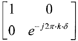
1/2 4 1 [I] 0 2 
1/2 3 
1/3 4 
1/4 -
Figure 12 shows a transmission rank adapted spatial multiplexing method. Symbol s(k) having symbol vectors s1(k) to sp(k) carried bysystem layers 1 to N*p are precoded by procoding matrix W(k), Q and P. The precoding matrix W(k) is a channel dependent precoder which is dependent upon a feedback of PMI (precoding matrix indication). Fourier matrix P may be defined as follows: - MathFigure 29
[Math.29]
- Precoding matrix Q may be in several different forms. Two examples of Q is Q= I where I is pxp identity matrix (in this case Q can be removed), or

- MathFigure 30
[Math.30]
- The precoded symbols y(k) are transformed by inverse fast Fourier transform (IFFT)
unit 115 and transmitted by transmitters ANT1T to ANT4T. - In this precoding CDD method, it is assumed that matrix W(k) is chosen according the PMI, which is obtained from uplink feedback. The uplink feedback refers to the feedback signal transmitted from the mobile receiver. PMI is defined as "precoding matrix index", and is used in the 3GPP LTE RAN1 discussion to indicate the choice of the codeword within a codebook, and this choice is being feedback from the mobile to the basestation. Once a PMI is obtained for a subband, the same choice of precoding matrix W(k) is applied throughout this subband. That is, W(k) maintains the same within the same subband. In high speed scenarios, however, the PMI feedback is not reliable and the PMI in the feedback cannot be used. This system is defined as an open-loop mode. It was not clear how to select precoder W(k) in this open-loop system case. On the assumption that there is a system codebook

- In this invention, several improved methods of selecting precoding matrix W(k) for high-speed open-loop precoding CDD are proposed for various antenna correlation configurations.
- In a related method, W(k) is selected according to a feedback without precoding matrix index (PMI) in the uplink for each given UE, and this feedback is different from the dynamic PMI. Same W(k) is applied to the UE across the scheduled subband. This method is especially useful in the configuration where the Node-B antennas are highly correlated.
- Selection based on SU-MIMO codebook
- In an embodiment of the current invention, the SU-MIMO codebook is denoted as CU(p), for a given transmission rank p that may be 1,2,3 or 4. The size of the codebook for rank p is denoted by Np. Codewords ci(p) are denoted in the code book as equation (31):
- MathFigure 31
[Math.31]
- Note that ci(p) is a G xp matrix. The codebook is predetermined in the standard in a matrix form.
- Furthermore, one way of selecting precoding matrix W(k) for rank p is to cycle through the codebook CU(p) as k increases. There are two options of how fast the precoding matrix may change. A "code book" is a set of predetermined reference data from which a precoder is selected when a predetermined situation is met. A "code word" refers to each data in a code book.
-
Figure 13 illustrates the first option of how fast the precoding matrix changes. The symbol s(k) to be precoded includes symbol vectors s1(1), s1(2),...,s1(p) (which is signal to be transmitted on the first groups of subcarriers) , s2(1), ..., s2(p), (which is signal to be transmitted on the second group of subcarriers),..., sN(1), ..., and sN(p) (which is signal to be transmitted on N-th group subcarriers). Note each group comprises of p subcarriers, and there are a total of N groups, and thus the total number of subcarriers is Nsub =N*p. Precoding matrix W(k) may change every p subcarriers within a subband. For example, transmission rank adapted symbol vectors s1(1) to s1(p) are precoded by the same precoding matrix W(k) which is shown as C1, transmission rank adapted symbol vectors s2(1) to s2(p) are precoded by the same precoding matrix W(k) which is C2 (not shown inFigure 13 ), and the transmission rank adapted symbol vectors sN(1) to sN(p) are precoded by the same procoding matrix CN. The precoded transmission rank adapted symbol vectors are then processed by IFFT unit and P/S unit in their corresponding transmission ranks, are summarized and transmitted to their corresponding transmitting antennas. Here, ANTGT indicates #G transmitting antenna. Mathematically, for any subcarrier k that satisfies
- MathFigure 32
[Math.32]
- where Np is the size of codebook.
- Note that "a" is a constant shift, and a typical value of "a" is 0. Also note that mod() is the modulo operation and

- The second option is as shown in
Figure 14 . The symbol s(k) to be precoded includes symbol vectors s1(1), s1(2),...,s1(p), s2(1), ..., s2(p),... , ..., sN(1), ..., and sN(p). The precoding matrix W(k) changes every subcarrier within the subband. For example, transmission rank adapted symbol vector s1(1) is precoded by the precoding matrix W(k) which is shown as C1, transmission rank adapted symbol vectors s1(2) is precoded by the precoding matrix W(k) which is C2 (not shown inFigure 14 ), the transmission rank adapted symbol vectors s1(p) is precoded by the procoding matrix Cp , and the transmission rank adapted symbol vectors sN(p) is precoded by the procoding matrix CNp. The precoded transmission rank adapted symbol vectors are then processed by IFFT unit and P/S unit in their corresponding transmission ranks, are summarized and transmitted to their corresponding transmitting antennas. Here, ANTGT indicates #G transmitting antenna. Mathematically, for any subcarrier k : - MathFigure 33
[Math.33]
- In
Figures 13 and14 , there are a total of N*p subcarriers. InFigure 13 , the codeword changes every p subcarriers, resulting in a total of N*p/p =N codewords; and inFigure 14 , the codeword changes every subcarrier, resulting in a total of N*p/1=N*p codewords. - In another embodiment of the current invention, for each codebook CU(p), subsets


- Furthermore, one way of selecting the precoding matrix for W(k) is to pick a subset CU,S(p) for a given rank p, and then cycle through this subset as k increases. There are two options of how fast the precoding matrix changes. In the first option, the precoding matrix W(k) changes every p subcarriers within the subband, or, mathematically, for any subcarrier k that satisfies

- MathFigure 34
[Math.34]
- In the second option, the precoding matrix W(k) changes every subcarrier within the subband, or, mathematically, for any subcarrier k:
- MathFigure 35
[Math.35]
- In another embodiment of the invention, W(k) is selected as one of the submatrices in the set CU(p), for a given rank p. And the W(k) is fixed for all the subcarriers in the subband scheduled for the UE.
- In a related method, a 4Tx structure system will be explained as an example. This embodiment, however, is not limited to a 4Tx structure system but may be applied to NTx structure system (a system having a number of transmitters other than 4). A 4Tx DFT matrix is defined as follows:
- MathFigure 36
[Math.36]
- Where

- MathFigure 37
[Math.37]
- MathFigure 38
[Math.38]
- MathFigure 39
[Math.39]
- For each set CF(p), subsets


rank 2 set is - MathFigure 40
[Math.40]
- Furthermore, one way of selecting the precoding matrix for W(k) is to pick a subset CF,S(p) for a given rank p, and then cycle through this subset as k increases. There are two options of how fast the precoding matrix changes.
- In the first option, the precoding matrix W(k) changes every p subcarriers within the subband, or, mathematically, for any subcarrier k that satisfies


- MathFigure 41
[Math.41]
- In the second option, the precoding mat[0080] In the second option, the precoding matrix W(k) changes every subcarrier within the subband, or, mathematically, for any subcarrier k:
- MathFigure 42
[Math.42]
- As an example, in case of p=2, a=0, the subset is chosen as
- MathFigure 43
[Math.43]
- If the first option is adopted, where the precoding matrix changes every p=2 subcarriers, the selecting of precoding matrix W(k) becomes:
- MathFigure 44
[Math.44]
- In a related method, W(k) is selected as one of the sub-W(k) is selected as one of the submatrices in the set CF(p), for a given rank p. And the W(k) is fixed for all the subcarriers in the subband scheduled for the UE.
- In a related method, the preceeding embodiments mentioned above are reversible (i.e. readably decodable) with advance reception of the precoded symbols by the receiver. In other words, the precoded symbols may be decoded in likely methods at the receiver. A precoded symbol may be decoded by a selected decoding matrix, the decoding matrix is selected by cycling through a decode code-book within a subband, and the decoding matrix may either change every p subcarrier or change every subcarrier within a subband. Also, the precoded symbol may be decoded by a selected decoding matrix, the decoding matrix is selected by cycling through a subset of the decode code-book, and the decoding matrix may either change every p subcarrier or change every subcarrier within a subband.
- The precoder is a part of the eNB baseband microprocessor.
Claims (8)
- A method for transmitting in a communication system, the method comprising:modulating a plurality of bits to generate a plurality of modulation symbols; andgenerating precoded symbols y(i) based on:

- The method of claim 1, wherein the elements of U are defined as Umn = e -j2πmn/υ , for m = 0,1,...,υ-1, and n = 0,1,...,υ-1
- The method of claim 1, wherein W(i) is cyclically selected by modulo N operation of a value derived from i/q, where i is the subcarrier index, q is υ, and N is a size of the subset of the codebook.
- The method of claim 1, wherein W(i) = Ck,
where Ck is a precoding matrix of the subset of the codebook, the index k being established by:
- An apparatus for transmitting in a communication system, the apparatus comprising:a modulator (111) to modulate a plurality of bits to generate a plurality of modulation symbols;
anda precoder (114) to generate precoded symbols y(i) based on where s(i) indicates the plurality of modulation symbols, W(i) is a precoding matrix of size P×υ, D(i) is a diagonal matrix of size υ×υ for support of large-delay cyclic delay diversity, U is a matrix of size υ×υ, P is the number of antenna ports, υ is the number of layers, and i is a subcarrier index, wherein W(i) is cyclically selected in a subset of a codebook based on the number of layers υ.
 - The apparatus of claim 5, wherein the elements of U are defined as Umn = e-j2πmn/υ , for m = 0, 1,..., υ-1, and n = 0, 1,...,υ-1.
- The apparatus of claim 5, wherein W(i) is cyclically selected by modulo N operation of a value derived from i/q, where i is the subcarrier index, q is υ, and N is a size of the subset of the codebook.
- The apparatus of claim 5, wherein W(i) = Ck,
where Ck is a precoding matrix of the subset of the codebook, the index k being established by:
Applications Claiming Priority (4)
| Application Number | Priority Date | Filing Date | Title |
|---|---|---|---|
| US92902707P | 2007-06-08 | 2007-06-08 | |
| US92945507P | 2007-06-28 | 2007-06-28 | |
| US12/155,097 US8325852B2 (en) | 2007-06-08 | 2008-05-29 | CDD precoding for open loop SU MIMO |
| PCT/KR2008/003212 WO2008150148A2 (en) | 2007-06-08 | 2008-06-09 | Cdd precoding for open loop su mimo |
Publications (3)
| Publication Number | Publication Date |
|---|---|
| EP2156588A2 EP2156588A2 (en) | 2010-02-24 |
| EP2156588A4 EP2156588A4 (en) | 2013-10-02 |
| EP2156588B1 true EP2156588B1 (en) | 2016-03-30 |
Family
ID=40094317
Family Applications (1)
| Application Number | Title | Priority Date | Filing Date |
|---|---|---|---|
| EP08766174.0A Active EP2156588B1 (en) | 2007-06-08 | 2008-06-09 | Cdd precoding for an open loop su-mimo system |
Country Status (5)
| Country | Link |
|---|---|
| US (2) | US8325852B2 (en) |
| EP (1) | EP2156588B1 (en) |
| CN (2) | CN102882578B (en) |
| MY (1) | MY145202A (en) |
| WO (1) | WO2008150148A2 (en) |
Families Citing this family (62)
| Publication number | Priority date | Publication date | Assignee | Title |
|---|---|---|---|---|
| US8160177B2 (en) * | 2007-06-25 | 2012-04-17 | Samsung Electronics Co., Ltd. | Transmit methods with delay diversity and space-frequency diversity |
| US9287951B2 (en) * | 2007-12-03 | 2016-03-15 | Telefonaktiebolaget L M Ericsson (Publ) | Precoder for spatial multiplexing, multiple antenna transmitter |
| WO2009072960A2 (en) * | 2007-12-03 | 2009-06-11 | Telefonaktiebolaget L M Ericsson (Publ) | Precoder for spatial multiplexing, multiple antenna transmitter |
| JP4652420B2 (en) * | 2008-01-08 | 2011-03-16 | 株式会社エヌ・ティ・ティ・ドコモ | User apparatus, transmission method, and mobile communication system |
| PT2232726T (en) * | 2008-01-14 | 2017-05-02 | ERICSSON TELEFON AB L M (publ) | Open loop precoder cycling in mimo communications |
| KR101409730B1 (en) * | 2008-01-17 | 2014-06-19 | 알까뗄 루슨트 | Method and device for cyclic delay mapping for the signal in the multi-antenna transmitter |
| KR101430476B1 (en) * | 2008-03-24 | 2014-08-18 | 엘지전자 주식회사 | A method for transmitting and receiving precoded signal in MIMO communication system |
| US8958408B1 (en) * | 2008-06-05 | 2015-02-17 | The Boeing Company | Coded aperture scanning |
| TWI506976B (en) * | 2008-07-02 | 2015-11-01 | Interdigital Patent Holdings | Method and apparatus for measuring and reporting a rank and a precoding matrix for multiple-input multiple-output communication |
| US8725186B2 (en) * | 2008-09-22 | 2014-05-13 | Ntt Docomo, Inc. | Base station apparatus, user equipment and precoding method |
| WO2010055676A1 (en) | 2008-11-14 | 2010-05-20 | パナソニック株式会社 | Wireless communication terminal apparatus, wireless communication base station apparatus, and cluster constellation setting method |
| KR101707680B1 (en) * | 2008-12-21 | 2017-02-17 | 엘지전자 주식회사 | Apparatus and method of transmitting information in wireless communication system |
| US8687731B2 (en) * | 2009-02-02 | 2014-04-01 | Qualcomm Incorporated | Uplink open-loop spatial multiplexing in wireless communications |
| US8494088B2 (en) * | 2009-04-27 | 2013-07-23 | Samsung Electronics Co., Ltd. | Transmitting/receiving apparatus and method thereof in codebook based multiple antenna system |
| US8693356B2 (en) | 2009-07-16 | 2014-04-08 | Ralink Technology Corp. | Method for wireless communication system and device using the same |
| US20110013575A1 (en) * | 2009-07-16 | 2011-01-20 | Yen-Chin Liao | Method of generating preamble sequence for wireless local area network system and device thereof |
| US8488539B2 (en) * | 2009-07-16 | 2013-07-16 | Ralink Technology Corp. | Method of generating preamble sequence |
| US20110013547A1 (en) * | 2009-07-16 | 2011-01-20 | Yen-Chin Liao | Method of generating preamble sequence for wireless communication system and device thereof |
| CN101997650B (en) * | 2009-08-28 | 2014-07-30 | 华为技术有限公司 | Transmission method, device and system of multi-antenna system data signals |
| CN102783112B (en) * | 2009-12-21 | 2015-08-05 | 瑞典爱立信有限公司 | Data modulation |
| US8958495B2 (en) * | 2010-01-08 | 2015-02-17 | Samsung Electronics Co., Ltd. | Codebook design method for multiple-input multiple-output (MIMO) communication system and method for using the codebook |
| CN102088340B (en) * | 2010-01-11 | 2013-04-17 | 电信科学技术研究院 | Method and device of multi-aerial system for transmitting and receiving information |
| US8644422B2 (en) * | 2010-02-12 | 2014-02-04 | Blackberry Limited | Low overhead PMI and CQI feedback and pairing schemes for MU-MIMO |
| JP2011254171A (en) * | 2010-05-31 | 2011-12-15 | Sharp Corp | Communication system, transmission device, transmission control method, transmission control program, and processor |
| US8548511B2 (en) * | 2010-06-21 | 2013-10-01 | Qualcomm Incorporated | Energy saving mode with maintained number of advertised transmit antennas |
| CN102299731B (en) * | 2010-06-28 | 2016-06-29 | 中兴通讯股份有限公司 | The discharger of ofdm system and the method for raising cyclic delay diversity performance |
| US9014287B2 (en) | 2010-08-24 | 2015-04-21 | Qualcomm Incorporated | Open loop MIMO mode for LTE-A uplink |
| KR20120030200A (en) * | 2010-09-17 | 2012-03-28 | 주식회사 팬택 | Apparatus and method of transmitting data using multiple antenna and beam forming |
| CN103004118B (en) | 2010-12-10 | 2016-04-27 | 松下电器(美国)知识产权公司 | Method for precoding, dispensing device |
| EP2673892A4 (en) | 2011-02-07 | 2016-09-14 | Intel Corp | Co-phasing of transmissions from multiple infrastructure nodes |
| CN107104716B (en) * | 2011-04-19 | 2020-10-02 | 太阳专利托管公司 | Signal generation method and device, and signal processing method and device |
| EP2518906B1 (en) * | 2011-04-29 | 2013-10-30 | NTT DoCoMo, Inc. | Method and apparatus for determining a precoding matrix for precoding symbols to be transmitted to a plurality of wireless devices |
| CN102255691B (en) * | 2011-07-13 | 2018-08-24 | 中兴通讯股份有限公司 | A kind of launching technique and device of uplink multiaerial system Open-Loop Spatial Multiplexing |
| CN102271027B (en) * | 2011-07-21 | 2018-03-23 | 中兴通讯股份有限公司 | A kind of recoding processing method and system of up Open-Loop Spatial Multiplexing |
| US8929473B2 (en) * | 2011-07-28 | 2015-01-06 | Samsung Electronics Co., Ltd. | Combining baseband processing and radio frequency beam steering in wireless communication systems |
| US9225482B2 (en) | 2011-10-17 | 2015-12-29 | Golba Llc | Method and system for MIMO transmission in a distributed transceiver network |
| TWI446770B (en) * | 2012-01-20 | 2014-07-21 | Nat Univ Tsing Hua | Communication system having data-dependent superimposed training mechanism and communication method thereof |
| KR20130110396A (en) * | 2012-03-29 | 2013-10-10 | 삼성전자주식회사 | Method and apparatus for reference signal design in mixed analog/digital beam forming system |
| US20150065153A1 (en) * | 2012-04-13 | 2015-03-05 | Nokia Corporation | Arrangement for Enhanced Multi-Transmit Antenna Sounding |
| KR101285848B1 (en) | 2012-06-29 | 2013-07-12 | 연세대학교 산학협력단 | A device for mimo system based on codebook and precoding method |
| US10020861B2 (en) * | 2012-08-08 | 2018-07-10 | Golba Llc | Method and system for distributed transceivers and mobile device connectivity |
| US9755716B2 (en) | 2013-03-07 | 2017-09-05 | Nec Corporation | Codebook construction |
| KR102115853B1 (en) * | 2013-03-07 | 2020-05-27 | 닛본 덴끼 가부시끼가이샤 | Codebook construction |
| CN103249225A (en) * | 2013-04-10 | 2013-08-14 | 安徽海聚信息科技有限责任公司 | WiFi (Wireless Fidelity) technology-based LED control system |
| US9806926B2 (en) * | 2013-11-04 | 2017-10-31 | Samsung Electronics Co., Ltd. | Multistage beamforming of multiple-antenna communication system |
| US9680542B2 (en) * | 2013-12-26 | 2017-06-13 | Telefonaktiebolaget Lm Ericsson (Publ) | Precoding in a wireless communication network |
| WO2015194230A1 (en) * | 2014-06-16 | 2015-12-23 | Nec Corporation | COMPUTING PMIs, PARTICULARLY IN WIRELESS COMMUNICATIONS SYSTEMS HAVING A THREE-DIMENSIONAL COMMUNICATIONS CHANNEL |
| CN107615694B (en) * | 2015-06-17 | 2021-02-05 | 苹果公司 | Method and precoding module for determining a precoding matrix |
| US10854995B2 (en) | 2016-09-02 | 2020-12-01 | Movandi Corporation | Wireless transceiver having receive antennas and transmit antennas with orthogonal polarizations in a phased array antenna panel |
| US10199717B2 (en) | 2016-11-18 | 2019-02-05 | Movandi Corporation | Phased array antenna panel having reduced passive loss of received signals |
| US10321332B2 (en) | 2017-05-30 | 2019-06-11 | Movandi Corporation | Non-line-of-sight (NLOS) coverage for millimeter wave communication |
| US10916861B2 (en) | 2017-05-30 | 2021-02-09 | Movandi Corporation | Three-dimensional antenna array module |
| US10484078B2 (en) | 2017-07-11 | 2019-11-19 | Movandi Corporation | Reconfigurable and modular active repeater device |
| WO2019052485A1 (en) * | 2017-09-12 | 2019-03-21 | Mediatek Inc. | Codebook-based uplink transmission in wireless communications |
| US10862559B2 (en) | 2017-12-08 | 2020-12-08 | Movandi Corporation | Signal cancellation in radio frequency (RF) device network |
| US10090887B1 (en) | 2017-12-08 | 2018-10-02 | Movandi Corporation | Controlled power transmission in radio frequency (RF) device network |
| US11088457B2 (en) | 2018-02-26 | 2021-08-10 | Silicon Valley Bank | Waveguide antenna element based beam forming phased array antenna system for millimeter wave communication |
| US10637159B2 (en) | 2018-02-26 | 2020-04-28 | Movandi Corporation | Waveguide antenna element-based beam forming phased array antenna system for millimeter wave communication |
| US10606790B2 (en) * | 2018-04-16 | 2020-03-31 | Intel Corporation | Precoding mechanism in PCI-express |
| US11205855B2 (en) | 2018-12-26 | 2021-12-21 | Silicon Valley Bank | Lens-enhanced communication device |
| US11145986B2 (en) | 2018-12-26 | 2021-10-12 | Silicon Valley Bank | Lens-enhanced communication device |
| US11121900B2 (en) * | 2019-05-03 | 2021-09-14 | Qualcomm Incorporated | Discrete Fourier transform size decomposition |
Family Cites Families (22)
| Publication number | Priority date | Publication date | Assignee | Title |
|---|---|---|---|---|
| JP4214440B2 (en) * | 2000-10-19 | 2009-01-28 | ソニー株式会社 | Data processing apparatus, data processing method, and recording medium |
| WO2005081481A1 (en) * | 2004-02-19 | 2005-09-01 | Ntt Docomo, Inc. | Channel estimator and method for estimating a channel transfer function and apparatus and method for providing pilot sequences |
| US7623439B2 (en) | 2004-05-20 | 2009-11-24 | Webster Mark A | Cyclic diversity systems and methods |
| EP1766789B1 (en) * | 2004-06-22 | 2019-02-27 | Apple Inc. | Methods and systems for enabling feedback in wireless communication networks |
| WO2006021227A1 (en) * | 2004-08-27 | 2006-03-02 | Ntt Docomo, Inc. | Apparatus and method for obtaining delay diversity |
| GB2423675B (en) | 2005-02-28 | 2009-08-19 | King S College London | Diversity transmitter and method |
| US20070041457A1 (en) | 2005-08-22 | 2007-02-22 | Tamer Kadous | Method and apparatus for providing antenna diversity in a wireless communication system |
| EP1941647B1 (en) * | 2005-10-27 | 2013-06-19 | Qualcomm Incorporated | Precoding for segment sensitive scheduling in wireless communication systems |
| US8760994B2 (en) * | 2005-10-28 | 2014-06-24 | Qualcomm Incorporated | Unitary precoding based on randomized FFT matrices |
| KR20070068300A (en) * | 2005-12-26 | 2007-06-29 | 삼성전자주식회사 | Apparatus and method for transmitting and receiving data in a communication system |
| TWI343200B (en) * | 2006-05-26 | 2011-06-01 | Lg Electronics Inc | Method and apparatus for signal generation using phase-shift based pre-coding |
| US7839835B2 (en) * | 2006-08-22 | 2010-11-23 | Nec Laboratories America, Inc. | Quantized precoding over a set of parallel channels |
| US7944985B2 (en) * | 2006-08-24 | 2011-05-17 | Interdigital Technology Corporation | MIMO transmitter and receiver for supporting downlink communication of single channel codewords |
| CA2819715A1 (en) * | 2006-11-06 | 2008-05-15 | Qualcomm Incorporated | Mimo transmission with layer permutation in a wireless communication system |
| DK3444967T3 (en) * | 2007-01-12 | 2021-02-15 | Ericsson Telefon Ab L M | Method and device in a wireless communication system |
| US8780771B2 (en) * | 2007-02-06 | 2014-07-15 | Qualcomm Incorporated | Cyclic delay diversity and precoding for wireless communication |
| US7995671B2 (en) * | 2007-02-09 | 2011-08-09 | Qualcomm Incorporated | Multiple-input multiple-output (MIMO) transmission with rank-dependent precoding |
| DK2119038T3 (en) * | 2007-02-13 | 2015-06-22 | Ericsson Telefon Ab L M | Combined precoding and cyclic delay diversity methods and systems |
| KR20080076683A (en) * | 2007-02-14 | 2008-08-20 | 엘지전자 주식회사 | Phase shift based precoding method and tranceiver supporting the same |
| US8259824B2 (en) * | 2007-05-23 | 2012-09-04 | Texas Instruments Incorporated | Nested precoding codebook structures for MIMO systems |
| EP2078443A1 (en) * | 2007-08-31 | 2009-07-15 | Fujitsu Limited | Feedback apparatus, feedback method, scheduling apparatus, and scheduling method |
| US20130321207A1 (en) * | 2012-05-31 | 2013-12-05 | Alcatel-Lucent Usa Inc. | Transforming precoded signals for wireless communication |
-
2008
- 2008-05-29 US US12/155,097 patent/US8325852B2/en active Active
- 2008-06-09 CN CN201210347735.2A patent/CN102882578B/en active Active
- 2008-06-09 MY MYPI20095010A patent/MY145202A/en unknown
- 2008-06-09 EP EP08766174.0A patent/EP2156588B1/en active Active
- 2008-06-09 CN CN200880019001.3A patent/CN101682453B/en active Active
- 2008-06-09 WO PCT/KR2008/003212 patent/WO2008150148A2/en active Application Filing
-
2012
- 2012-12-04 US US13/693,873 patent/US9356667B2/en active Active
Also Published As
| Publication number | Publication date |
|---|---|
| WO2008150148A2 (en) | 2008-12-11 |
| US20130094344A1 (en) | 2013-04-18 |
| CN101682453B (en) | 2014-11-19 |
| CN102882578B (en) | 2016-08-24 |
| US8325852B2 (en) | 2012-12-04 |
| EP2156588A4 (en) | 2013-10-02 |
| MY145202A (en) | 2012-01-13 |
| CN101682453A (en) | 2010-03-24 |
| US9356667B2 (en) | 2016-05-31 |
| CN102882578A (en) | 2013-01-16 |
| US20080303701A1 (en) | 2008-12-11 |
| WO2008150148A3 (en) | 2009-01-29 |
| EP2156588A2 (en) | 2010-02-24 |
Similar Documents
| Publication | Publication Date | Title |
|---|---|---|
| EP2156588B1 (en) | Cdd precoding for an open loop su-mimo system | |
| US8837622B2 (en) | Transmit methods with delay diversity and space-frequency diversity | |
| EP2161850B1 (en) | Data transmitting and receiving method using phase shift based precoding and transceiver supporting the same | |
| EP2127134B1 (en) | Precoding apparatus and method in a wireless communication system using multiple input multiple output | |
| US8369450B2 (en) | Pilot boosting and traffic to pilot ratio estimation in a wireless communication system | |
| KR101056614B1 (en) | Data transmission method in multi-antenna system | |
| RU2446574C2 (en) | Method for data transmission and receive using based on phase shift of precoding and transceiver to support same | |
| JP4995319B2 (en) | Multi-user multiple-input multiple-output feedback and transfer in wireless communication systems | |
| EP2272180B1 (en) | Method for transmitting and receiving signals in open-loop spatial multiplexing mode | |
| KR101440628B1 (en) | Apparatus and method for data transmission using transmit diversity in sc-fdma system | |
| KR101567078B1 (en) | Apparatus and method for data transmission using multiple antenna | |
| KR20100072146A (en) | Apparatus and method of transmitting information in wireless communication system | |
| CN113381789B (en) | Physical layer channel processing method and device for multi-input multi-output data antenna | |
| Jing et al. | The Scheme of MIMO-OFDM Linear Precoding Based on CDD | |
| Ding et al. | Mali 3] S1-e |
Legal Events
| Date | Code | Title | Description |
|---|---|---|---|
| PUAI | Public reference made under article 153(3) epc to a published international application that has entered the european phase |
Free format text: ORIGINAL CODE: 0009012 |
|
| 17P | Request for examination filed |
Effective date: 20091125 |
|
| AK | Designated contracting states |
Kind code of ref document: A2 Designated state(s): AT BE BG CH CY CZ DE DK EE ES FI FR GB GR HR HU IE IS IT LI LT LU LV MC MT NL NO PL PT RO SE SI SK TR |
|
| AX | Request for extension of the european patent |
Extension state: AL BA MK RS |
|
| DAX | Request for extension of the european patent (deleted) | ||
| RAP1 | Party data changed (applicant data changed or rights of an application transferred) |
Owner name: SAMSUNG ELECTRONICS CO., LTD. |
|
| A4 | Supplementary search report drawn up and despatched |
Effective date: 20130829 |
|
| RIC1 | Information provided on ipc code assigned before grant |
Ipc: H04L 25/03 20060101ALN20130823BHEP Ipc: H04B 7/04 20060101AFI20130823BHEP Ipc: H04L 27/26 20060101ALI20130823BHEP Ipc: H04L 5/00 20060101ALN20130823BHEP Ipc: H04B 7/06 20060101ALI20130823BHEP |
|
| 17Q | First examination report despatched |
Effective date: 20140507 |
|
| REG | Reference to a national code |
Ref country code: DE Ref legal event code: R079 Ref document number: 602008043195 Country of ref document: DE Free format text: PREVIOUS MAIN CLASS: H04J0011000000 Ipc: H04B0007040000 |
|
| RIC1 | Information provided on ipc code assigned before grant |
Ipc: H04B 7/06 20060101ALI20151013BHEP Ipc: H04L 25/03 20060101ALN20151013BHEP Ipc: H04L 27/26 20060101ALI20151013BHEP Ipc: H04L 1/06 20060101ALI20151013BHEP Ipc: H04B 7/04 20060101AFI20151013BHEP |
|
| GRAP | Despatch of communication of intention to grant a patent |
Free format text: ORIGINAL CODE: EPIDOSNIGR1 |
|
| INTG | Intention to grant announced |
Effective date: 20151204 |
|
| GRAS | Grant fee paid |
Free format text: ORIGINAL CODE: EPIDOSNIGR3 |
|
| GRAA | (expected) grant |
Free format text: ORIGINAL CODE: 0009210 |
|
| AK | Designated contracting states |
Kind code of ref document: B1 Designated state(s): AT BE BG CH CY CZ DE DK EE ES FI FR GB GR HR HU IE IS IT LI LT LU LV MC MT NL NO PL PT RO SE SI SK TR |
|
| REG | Reference to a national code |
Ref country code: GB Ref legal event code: FG4D |
|
| REG | Reference to a national code |
Ref country code: CH Ref legal event code: EP |
|
| REG | Reference to a national code |
Ref country code: AT Ref legal event code: REF Ref document number: 786388 Country of ref document: AT Kind code of ref document: T Effective date: 20160415 |
|
| REG | Reference to a national code |
Ref country code: IE Ref legal event code: FG4D |
|
| REG | Reference to a national code |
Ref country code: DE Ref legal event code: R096 Ref document number: 602008043195 Country of ref document: DE |
|
| REG | Reference to a national code |
Ref country code: SE Ref legal event code: TRGR |
|
| REG | Reference to a national code |
Ref country code: FR Ref legal event code: PLFP Year of fee payment: 9 |
|
| REG | Reference to a national code |
Ref country code: NL Ref legal event code: FP |
|
| REG | Reference to a national code |
Ref country code: LT Ref legal event code: MG4D |
|
| PG25 | Lapsed in a contracting state [announced via postgrant information from national office to epo] |
Ref country code: GR Free format text: LAPSE BECAUSE OF FAILURE TO SUBMIT A TRANSLATION OF THE DESCRIPTION OR TO PAY THE FEE WITHIN THE PRESCRIBED TIME-LIMIT Effective date: 20160701 Ref country code: NO Free format text: LAPSE BECAUSE OF FAILURE TO SUBMIT A TRANSLATION OF THE DESCRIPTION OR TO PAY THE FEE WITHIN THE PRESCRIBED TIME-LIMIT Effective date: 20160630 Ref country code: HR Free format text: LAPSE BECAUSE OF FAILURE TO SUBMIT A TRANSLATION OF THE DESCRIPTION OR TO PAY THE FEE WITHIN THE PRESCRIBED TIME-LIMIT Effective date: 20160330 |
|
| REG | Reference to a national code |
Ref country code: AT Ref legal event code: MK05 Ref document number: 786388 Country of ref document: AT Kind code of ref document: T Effective date: 20160330 |
|
| PG25 | Lapsed in a contracting state [announced via postgrant information from national office to epo] |
Ref country code: LT Free format text: LAPSE BECAUSE OF FAILURE TO SUBMIT A TRANSLATION OF THE DESCRIPTION OR TO PAY THE FEE WITHIN THE PRESCRIBED TIME-LIMIT Effective date: 20160330 Ref country code: LV Free format text: LAPSE BECAUSE OF FAILURE TO SUBMIT A TRANSLATION OF THE DESCRIPTION OR TO PAY THE FEE WITHIN THE PRESCRIBED TIME-LIMIT Effective date: 20160330 |
|
| PG25 | Lapsed in a contracting state [announced via postgrant information from national office to epo] |
Ref country code: IS Free format text: LAPSE BECAUSE OF FAILURE TO SUBMIT A TRANSLATION OF THE DESCRIPTION OR TO PAY THE FEE WITHIN THE PRESCRIBED TIME-LIMIT Effective date: 20160730 Ref country code: PL Free format text: LAPSE BECAUSE OF FAILURE TO SUBMIT A TRANSLATION OF THE DESCRIPTION OR TO PAY THE FEE WITHIN THE PRESCRIBED TIME-LIMIT Effective date: 20160330 Ref country code: EE Free format text: LAPSE BECAUSE OF FAILURE TO SUBMIT A TRANSLATION OF THE DESCRIPTION OR TO PAY THE FEE WITHIN THE PRESCRIBED TIME-LIMIT Effective date: 20160330 |
|
| PG25 | Lapsed in a contracting state [announced via postgrant information from national office to epo] |
Ref country code: RO Free format text: LAPSE BECAUSE OF FAILURE TO SUBMIT A TRANSLATION OF THE DESCRIPTION OR TO PAY THE FEE WITHIN THE PRESCRIBED TIME-LIMIT Effective date: 20160330 Ref country code: SK Free format text: LAPSE BECAUSE OF FAILURE TO SUBMIT A TRANSLATION OF THE DESCRIPTION OR TO PAY THE FEE WITHIN THE PRESCRIBED TIME-LIMIT Effective date: 20160330 Ref country code: AT Free format text: LAPSE BECAUSE OF FAILURE TO SUBMIT A TRANSLATION OF THE DESCRIPTION OR TO PAY THE FEE WITHIN THE PRESCRIBED TIME-LIMIT Effective date: 20160330 Ref country code: CZ Free format text: LAPSE BECAUSE OF FAILURE TO SUBMIT A TRANSLATION OF THE DESCRIPTION OR TO PAY THE FEE WITHIN THE PRESCRIBED TIME-LIMIT Effective date: 20160330 Ref country code: PT Free format text: LAPSE BECAUSE OF FAILURE TO SUBMIT A TRANSLATION OF THE DESCRIPTION OR TO PAY THE FEE WITHIN THE PRESCRIBED TIME-LIMIT Effective date: 20160801 Ref country code: ES Free format text: LAPSE BECAUSE OF FAILURE TO SUBMIT A TRANSLATION OF THE DESCRIPTION OR TO PAY THE FEE WITHIN THE PRESCRIBED TIME-LIMIT Effective date: 20160330 |
|
| PG25 | Lapsed in a contracting state [announced via postgrant information from national office to epo] |
Ref country code: BE Free format text: LAPSE BECAUSE OF FAILURE TO SUBMIT A TRANSLATION OF THE DESCRIPTION OR TO PAY THE FEE WITHIN THE PRESCRIBED TIME-LIMIT Effective date: 20160330 |
|
| REG | Reference to a national code |
Ref country code: DE Ref legal event code: R097 Ref document number: 602008043195 Country of ref document: DE |
|
| PG25 | Lapsed in a contracting state [announced via postgrant information from national office to epo] |
Ref country code: MC Free format text: LAPSE BECAUSE OF FAILURE TO SUBMIT A TRANSLATION OF THE DESCRIPTION OR TO PAY THE FEE WITHIN THE PRESCRIBED TIME-LIMIT Effective date: 20160330 Ref country code: DK Free format text: LAPSE BECAUSE OF FAILURE TO SUBMIT A TRANSLATION OF THE DESCRIPTION OR TO PAY THE FEE WITHIN THE PRESCRIBED TIME-LIMIT Effective date: 20160330 |
|
| REG | Reference to a national code |
Ref country code: CH Ref legal event code: PL |
|
| PLBE | No opposition filed within time limit |
Free format text: ORIGINAL CODE: 0009261 |
|
| STAA | Information on the status of an ep patent application or granted ep patent |
Free format text: STATUS: NO OPPOSITION FILED WITHIN TIME LIMIT |
|
| 26N | No opposition filed |
Effective date: 20170103 |
|
| REG | Reference to a national code |
Ref country code: IE Ref legal event code: MM4A |
|
| PG25 | Lapsed in a contracting state [announced via postgrant information from national office to epo] |
Ref country code: LI Free format text: LAPSE BECAUSE OF NON-PAYMENT OF DUE FEES Effective date: 20160630 Ref country code: CH Free format text: LAPSE BECAUSE OF NON-PAYMENT OF DUE FEES Effective date: 20160630 |
|
| REG | Reference to a national code |
Ref country code: FR Ref legal event code: PLFP Year of fee payment: 10 |
|
| PG25 | Lapsed in a contracting state [announced via postgrant information from national office to epo] |
Ref country code: IE Free format text: LAPSE BECAUSE OF NON-PAYMENT OF DUE FEES Effective date: 20160609 Ref country code: SI Free format text: LAPSE BECAUSE OF FAILURE TO SUBMIT A TRANSLATION OF THE DESCRIPTION OR TO PAY THE FEE WITHIN THE PRESCRIBED TIME-LIMIT Effective date: 20160330 |
|
| REG | Reference to a national code |
Ref country code: FR Ref legal event code: PLFP Year of fee payment: 11 |
|
| PG25 | Lapsed in a contracting state [announced via postgrant information from national office to epo] |
Ref country code: CY Free format text: LAPSE BECAUSE OF FAILURE TO SUBMIT A TRANSLATION OF THE DESCRIPTION OR TO PAY THE FEE WITHIN THE PRESCRIBED TIME-LIMIT Effective date: 20160330 Ref country code: HU Free format text: LAPSE BECAUSE OF FAILURE TO SUBMIT A TRANSLATION OF THE DESCRIPTION OR TO PAY THE FEE WITHIN THE PRESCRIBED TIME-LIMIT; INVALID AB INITIO Effective date: 20080609 |
|
| PG25 | Lapsed in a contracting state [announced via postgrant information from national office to epo] |
Ref country code: MT Free format text: LAPSE BECAUSE OF NON-PAYMENT OF DUE FEES Effective date: 20160630 Ref country code: LU Free format text: LAPSE BECAUSE OF NON-PAYMENT OF DUE FEES Effective date: 20160609 Ref country code: TR Free format text: LAPSE BECAUSE OF FAILURE TO SUBMIT A TRANSLATION OF THE DESCRIPTION OR TO PAY THE FEE WITHIN THE PRESCRIBED TIME-LIMIT Effective date: 20160330 |
|
| PG25 | Lapsed in a contracting state [announced via postgrant information from national office to epo] |
Ref country code: BG Free format text: LAPSE BECAUSE OF FAILURE TO SUBMIT A TRANSLATION OF THE DESCRIPTION OR TO PAY THE FEE WITHIN THE PRESCRIBED TIME-LIMIT Effective date: 20160330 |
|
| PGFP | Annual fee paid to national office [announced via postgrant information from national office to epo] |
Ref country code: NL Payment date: 20230523 Year of fee payment: 16 Ref country code: IT Payment date: 20230523 Year of fee payment: 16 Ref country code: FR Payment date: 20230522 Year of fee payment: 16 Ref country code: DE Payment date: 20230522 Year of fee payment: 16 |
|
| PGFP | Annual fee paid to national office [announced via postgrant information from national office to epo] |
Ref country code: SE Payment date: 20230523 Year of fee payment: 16 Ref country code: FI Payment date: 20230522 Year of fee payment: 16 |
|
| PGFP | Annual fee paid to national office [announced via postgrant information from national office to epo] |
Ref country code: GB Payment date: 20230523 Year of fee payment: 16 |