EP2155284B1 - Neues flüssigkeitsmanagementsystem für präzise kontinuierliche blutfiltrierung - Google Patents
Neues flüssigkeitsmanagementsystem für präzise kontinuierliche blutfiltrierung Download PDFInfo
- Publication number
- EP2155284B1 EP2155284B1 EP08770325.2A EP08770325A EP2155284B1 EP 2155284 B1 EP2155284 B1 EP 2155284B1 EP 08770325 A EP08770325 A EP 08770325A EP 2155284 B1 EP2155284 B1 EP 2155284B1
- Authority
- EP
- European Patent Office
- Prior art keywords
- fluid
- container
- replacement fluid
- ultrafiltrate
- blood
- Prior art date
- Legal status (The legal status is an assumption and is not a legal conclusion. Google has not performed a legal analysis and makes no representation as to the accuracy of the status listed.)
- Not-in-force
Links
Images


Classifications
-
- A—HUMAN NECESSITIES
- A61—MEDICAL OR VETERINARY SCIENCE; HYGIENE
- A61M—DEVICES FOR INTRODUCING MEDIA INTO, OR ONTO, THE BODY; DEVICES FOR TRANSDUCING BODY MEDIA OR FOR TAKING MEDIA FROM THE BODY; DEVICES FOR PRODUCING OR ENDING SLEEP OR STUPOR
- A61M1/00—Suction or pumping devices for medical purposes; Devices for carrying-off, for treatment of, or for carrying-over, body-liquids; Drainage systems
- A61M1/34—Filtering material out of the blood by passing it through a membrane, i.e. hemofiltration or diafiltration
- A61M1/342—Adding solutions to the blood, e.g. substitution solutions
- A61M1/3441—Substitution rate control as a function of the ultrafiltration rate
- A61M1/3448—Substitution rate control as a function of the ultrafiltration rate by mechanically linked pumps in both ultra-filtrate and substitution flow line
-
- A—HUMAN NECESSITIES
- A61—MEDICAL OR VETERINARY SCIENCE; HYGIENE
- A61M—DEVICES FOR INTRODUCING MEDIA INTO, OR ONTO, THE BODY; DEVICES FOR TRANSDUCING BODY MEDIA OR FOR TAKING MEDIA FROM THE BODY; DEVICES FOR PRODUCING OR ENDING SLEEP OR STUPOR
- A61M1/00—Suction or pumping devices for medical purposes; Devices for carrying-off, for treatment of, or for carrying-over, body-liquids; Drainage systems
- A61M1/34—Filtering material out of the blood by passing it through a membrane, i.e. hemofiltration or diafiltration
- A61M1/342—Adding solutions to the blood, e.g. substitution solutions
- A61M1/3441—Substitution rate control as a function of the ultrafiltration rate
- A61M1/3444—Substitution rate control as a function of the ultrafiltration rate in which the collected ultra-filtrate expels an equal volume of substitution fluid from a reservoir
-
- A—HUMAN NECESSITIES
- A61—MEDICAL OR VETERINARY SCIENCE; HYGIENE
- A61M—DEVICES FOR INTRODUCING MEDIA INTO, OR ONTO, THE BODY; DEVICES FOR TRANSDUCING BODY MEDIA OR FOR TAKING MEDIA FROM THE BODY; DEVICES FOR PRODUCING OR ENDING SLEEP OR STUPOR
- A61M1/00—Suction or pumping devices for medical purposes; Devices for carrying-off, for treatment of, or for carrying-over, body-liquids; Drainage systems
- A61M1/36—Other treatment of blood in a by-pass of the natural circulatory system, e.g. temperature adaptation, irradiation ; Extra-corporeal blood circuits
- A61M1/3621—Extra-corporeal blood circuits
- A61M1/3666—Cardiac or cardiopulmonary bypass, e.g. heart-lung machines
-
- A—HUMAN NECESSITIES
- A61—MEDICAL OR VETERINARY SCIENCE; HYGIENE
- A61M—DEVICES FOR INTRODUCING MEDIA INTO, OR ONTO, THE BODY; DEVICES FOR TRANSDUCING BODY MEDIA OR FOR TAKING MEDIA FROM THE BODY; DEVICES FOR PRODUCING OR ENDING SLEEP OR STUPOR
- A61M1/00—Suction or pumping devices for medical purposes; Devices for carrying-off, for treatment of, or for carrying-over, body-liquids; Drainage systems
- A61M1/14—Dialysis systems; Artificial kidneys; Blood oxygenators ; Reciprocating systems for treatment of body fluids, e.g. single needle systems for hemofiltration or pheresis
- A61M1/16—Dialysis systems; Artificial kidneys; Blood oxygenators ; Reciprocating systems for treatment of body fluids, e.g. single needle systems for hemofiltration or pheresis with membranes
- A61M1/1698—Blood oxygenators with or without heat-exchangers
Definitions
- the present invention relates to a system for fluid management in critically ill patients. More particularly, the present invention relates to a system for fluid management that is continuous, automated, and accurate for treatment of critically ill patients who also require extracorporeal membrane oxygenation treatment.
- Extracorporeal life support is a widely used technique in intensive care units to assist patients with severe organ deficiencies.
- extracorporeal membrane oxygenation provides life-saving temporary heart and lung support to patients who experience cardiac and/or respiratory failure unresponsive to standard ventilator and pharmacologic management.
- the clinical implementation of ECMO varies, but generally consists of a drain cannula through which blood is drained from the patient's venous system, a roller or centrifugal pump, a membrane oxygenator that oxygenates the blood and removes carbon dioxide, a bladder pressure module, a heat exchanger, and an arterial cannula through which the oxygenated blood is returned to the patient's arterial system.
- Fluid restriction can be employed in management; however this is often at the expense of decreasing caloric intake, which could be detrimental to improving overall outcomes. Treating or preventing fluid overload in this setting can require aggressive use of diuretics, which has been suggested to worsen outcomes in critically ill adults with renal failure.
- Renal support can be provided by a continuous renal replacement therapy (CRRT) such as continuous venovenous hemofiltration (CVVH).
- CRRT continuous renal replacement therapy
- CVVH continuous venovenous hemofiltration
- This technique allows for precise control of fluid balance by providing continuous fluid, electrolyte and toxin clearance even in the absence of adequate native renal function via convective processes through a permeable membrane.
- the hemofiltration retains proteins and cellular components of the intravascular space and eliminates plasma water and dissolved solutes.
- a typical CVVH setup consists of a hemofilter and a pair of pumps to achieve the drainage of the ultrafiltrate which is discarded and the delivery of replacement fluid, respectively. The portion of the ultrafiltrate that corresponds to body weight loss within a patient is discarded merely as removal filtrate.
- CVVH has also been used in combination with other extracorporeal therapies, including ECMO.
- a single roller pump drives simultaneously the blood in the ECMO and CVVH circuits. Blood from the oxygenator is drained to the hemofilter and returns to the ECMO circuit via the ECMO bladder.
- percent fluid overload was correlated with mortality in patients receiving CVVH.
- the benefits of a combined ECMO-CVVH therapy were assessed to treat neonatal cardiac and respiratory failure. The results demonstrated that the reduction of fluid overload via CVVH could lead to a significant improvement in both oxygenation and cardiac output.
- similar benefits were observed when implementing CVVH along with ECMO in the pediatric intensive care unit. Those results suggest that the use of CVVH during ECMO is associated with improved fluid balance and caloric intake with less use of diuretics compared to standard ECMO approaches.
- CVVH is a common method of providing renal replacement therapy to critically ill and hemodynamically unstable patients in the pediatric intensive care unit.
- CVVH device for use in the neonatal and pediatric populations.
- CVVH devices approved for adults to treat children.
- CVVH devices are used on smaller patients, similar inaccuracy in fluid management as described above occur and complications are common.
- the present invention is an accurate continuous venovenous hemofiltration (CVVH) fluid management system that is configured for operation as a stand alone unit and for integration with an ECMO circuit. It is an objective of the CVVH system to produce either a zero or negative fluid balance between the replacement fluid delivered to the patient and the ultrafiltrate extracted from the hemofilter.
- CVVH continuous venovenous hemofiltration
- a method for managing fluid for accurate continuous venovenous hemofiltration comprising the steps of filling a first container with replacement fluid; continuously filtering unfiltered blood to extract ultrafiltrate; transferring the replacement fluid from the first container to the filtered blood; occurring simultaneously with the performance of the previous step, transferring the ultrafiltrate to a second container in an amount equal to the amount of replacement fluid transferred from the first container; continuously monitoring the state of replacement fluid in the first container and the state of ultrafiltrate in the second container; upon detecting that the first container no longer contains replacement fluid, stopping the transfer of ultrafiltrate to the second container; after transferring all of the replacement fluid from the first container, refilling the first container with additional replacement fluid; and occurring simultaneously with the performance of the previous step, emptying the ultrafiltrate that is in the second container so that the second container no longer contains ultrafiltrate.
- a method not part of the present invention further comprises the step of repeating the foregoing steps to achieve a zero fluid balance between the ultrafiltrate extracted from the filtered blood and the replacement fluid transferred to the filtered blood.
- the method of the present invention further comprises the steps of transferring a portion of the replacement fluid to a third container so that the portion of replacement fluid transferred to the third container is not combined with the filtered blood and emptying the portion of the replacement fluid that is in the third container so that the third container no longer contains replacement fluid.
- a method of the present invention may also comprise the step of continuously monitoring a patient to determine the need for zero fluid balance and negative fluid balance.
- the present invention discloses a system for managing fluid for accurate continuous venovenous hemofiltration, comprising a hemofilter configured to continuously filter unfiltered blood to extract ultrafiltrate, thereby configured to produce filtered blood; a first container filled with replacement fluid, wherein the replacement fluid is configured to be transferred from the container to the filtered blood; a second container and the first container coupled to a translating arm, wherein the translating arm is configured to move to simultaneously allow the replacement fluid to be transferred from the first container to the filtered blood and allow the ultrafiltrate to be transferred from the hemofilter to the second container, the amount of the replacement fluid and the ultrafiltrate transferred being equal to each other; at least one sensor being structurally connected to the translating arm to continuously monitor the relative position of the translating arm, thereby configure to determine whether there is replacement fluid contained in the first container and ultrafiltrate contained in the second container; upon at least one sensor configure to detect that the translating arm is in a minimum or a maximum position in connection with the first container and the second container, means for causing the translating arm to stop and reverse its direction
- the present invention discloses a system further comprising a third container for containing a portion of the replacement fluid that is configured to be transferred from the first container to the filtered blood so that the portion of replacement fluid configured to be transferred to the third container is not combined with the filtered blood, thereby producing a negative fluid balance between the ultrafiltrate configured to be extracted from the filtered blood and the replacement fluid configured to be transferred to the filtered blood.
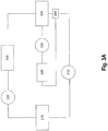
- the present invention is a combined ECMO-CVVH system 300 comprised of an ECMO bladder 305, a blood pump 310, an oxygenator 315, and a flow probe 325.
- Blood is continuously drained from a patient's venous system and circulated through the ECMO bladder 305.
- the blood pump 310 draws blood from the ECMO bladder 305, which works like the right atrium.
- the function of this ECMO bladder 305 is to prevent negative pressure from pulling the vessel wall into the cannula and to reduce the risk of damage to the vena cava.
- the blood pump 310 serves as an artificial heart that drives the blood simultaneously through the entire combined ECMO-CVVH system 300.
- the blood is carried through the oxygenator 315, which serves as an artificial lung that oxygenates the blood and removes carbon dioxide.
- pump 310 causes the oxygenated blood to be carried into the patient.
- the flow probe 325 is used to physically test the amount of fluid that is running in the circuit.
- the output of the flow probe 325 is a number representative of the amount of fluid running in the circuit, measured in liters per hour.
- the CVVH device 320 is inserted between the blood pump 310 and the oxygenator 315.
- the blood pump 310 drives the deoxygenated blood through the CVVH device 320.
- the novel CVVH device 320 described in greater detail below in connection with Figures 4A- 9B , is configured to directly measure the volume of fluid removed from a patient during therapy and utilize that measurement in order to determine a more accurate amount of replacement fluid that is to be returned to the patient.
- This aspect of the present invention may be utilized in a stand alone CVVH device or within the CVVH portion of the combined ECMO-CVVH system 300.
- the novel aspect of the CVVH portion of the present invention facilitates optimal return of replacement fluid.
- FIG. 3B illustrates an alternative embodiment of the present invention, a combined ECMO-CVVH system 300 comprised of an ECMO bladder 305, an ECMO blood pump 310, an oxygenator 315, a flow probe 325, a novel CVVH device 320, a CVVH blood pump 335, and a post bladder blood access port 340.
- Blood is continuously drained from a patient's venous system and circulated through the ECMO bladder 305.
- the ECMO blood pump 310 draws blood from the ECMO bladder 305, which works like the right atrium.
- the function of this ECMO bladder 305 is to prevent negative pressure from pulling the vessel wall into the cannula and to reduce the risk of damage to the vena cava.
- the ECMO blood pump 310 serves as an artificial heart that drives the blood through the ECMO circuit 300 and back to the patient.
- the blood is carried through the oxygenator 315, which serves as an artificial lung that oxygenates the blood and removes carbon dioxide. Once the blood has been oxygenated, the ECMO blood pump 310 causes the oxygenated blood to be carried into the patient.
- the CVVH device 320 is inserted between the ECMO blood pump 310 and the ECMO bladder 305.
- a CVVH blood pump 335 drives deoxygenated blood from the ECMO bladder 305 through the CVVH device 320 rather than relying on the ECMO blood pump 310 to drive the blood.
- the novel CVVH device 320 will be described in greater detail below in connection with Figures 4A-9B .
- FIGS. 4A and 4B aspects of CVVH system 400 illustrating the principles of "conservation of volume” in fluid management as applied in the present invention are shown.
- a unique linear positioner 402 is employed as shown in Figures 4A and 4B .
- the linear positioner 402 translates within a cylinder 405 and simultaneously controls both the delivery of replacement fluid 410 from a replacement fluid bag 411 and the removal of ultrafiltrate 415 after the blood has been filtered by a hemofilter 416.
- the linear positioner 402 divides the cylinder 405 into two chambers, namely replacement fluid chamber 420 and ultrafiltrate fluid chamber 425.
- the replacement fluid chamber 420 is dedicated to the delivery of replacement fluid 410 and the ultrafiltrate fluid chamber 425 is dedicated to the drainage of ultrafiltrate 415.
- the linear positioner 402 which is commercially available, facilitates balanced removal of ultrafiltrate and delivery of replacement fluids, hi the present embodiment, linear positioner 402, model number LP28-T0150-D01-G21-M1322-H3-L2, is manufactured by Parker Hannifin Corporation of Cleveland Ohio. It is contemplated that other linear positioners may be utilized so long as they perform the function of operating both the replacement fluid and ultrafiltration piston-syringes.
- the pinch valves utilized in the present embodiment are also commercially available, model number 100P3-MP12-05-S-F, manufactured by Bio Chem Valve hie, of Boonton, New Jersey. It is contemplated that other pinch valves or valve systems may be used.
- DE3801316A1 a system for managing fluid for accurate continuous venovenous hemofiltration is disclosed. Similarly to the present embodiment herein, the system comprises a hemofilter, a first container filled with replacement fluid and a second container into which ultrafiltrate from the hemofilter is transferred. The two containers are connected to a translating arm which facilitates the transfer of the replacement fluid from the first container simultaneously as the ultrafiltrate is transferred into the second container.
- the system disclosed herein comprises advantages over DE3801316A1 in terms of monitoring and adjusting the translating arm, which will be described further.
- a syringe-pump system 430 consisting of a syringe 431 and piston 432, a negative fluid balance bag 435, and valves 470 and 475 are located downstream of the replacement fluid chamber 420.
- the syringe-pump system 430 removes some replacement fluid 410 before its delivery to an ECMO bladder in order to achieve a net negative fluid balance.
- the syringe pump system 430 utilized in the present embodiment of the invention is commercially available, model 309653, manufactured by Becton Dickinson of Franklin Lakes, New Jersey. It is contemplated that syringes other than the specific model identified herein may be utilized, so long as they perform the function of facilitating a negative fluid balance within the system.
- Valves 450, 455, 460, 465, 470, and 475 are used to control the flow of filtered blood and replacement fluid in the system.
- Valve 450 is positioned between the fluid replacement bag 41 land the replacement fluid chamber 420.
- Valve 455 is positioned between the replacement fluid chamber 420 and the filtered blood.
- Valve 460 is positioned between the hemofilter 416 and the ultrafiltrate fluid chamber 425.
- Valve 465 is positioned between the ultrafiltrate fluid chamber 425 and the drainage bag 445.
- Valve 470 is positioned downstream between the filtered blood and the syringe 431 and valve 475 is positioned between the negative balance bag 435 and the syringe 431.
- valve 460 is open and valve 465 is closed, thereby allowing ultrafiltrate 415 to enter and fill the ultrafiltrate fluid chamber 425.
- valve 450 is closed and valve 455 is open, thereby allowing replacement fluid 410 to exit the replacement fluid chamber 420.
- the system may be configured to generate a net negative fluid balance in order to correct the fluid overload.
- a net negative fluid balance is achieved using the syringe pump system 430 located downstream of the replacement fluid chamber 420.
- valve 470 is open and valve 475 is closed, thereby allowing a portion of the replacement fluid to be captured in the syringe 431 of the syringe-pump system 430. Hence, the captured portion of replacement fluid will not enter the ECMO bladder.
- the system automatically pulls up 500ml of replacement fluid from the replacement fluid bag 411. If the 500ml of replacement fluid is pushed back into the patient, there would be an even balance.
- valve 470 is opened so that replacement fluid 410 may be extracted and placed in the negative fluid balance bag 435. In this example, the amount of replacement fluid that is delivered back to the ECMO bladder is less than 500 ml.
- the present invention shall include a processor, and a software module that operatively controls the motion of the syringe pump system 430 and the linear positioner 402.
- the linear positioner 402 controls the replacement fluid piston-syringe and the ultrafiltration piston-syringe and thereby controls the rate of fluid replacement and extraction with respect to each other.
- the syringe pump system 430 is automatically engaged by the processor and software controls to facilitate an appropriate level of replacement fluid removal from the circuit.
- the processor and software module shall be completely integrated and are operatively connected to a user interface that allows a system user to input data representative of the rate at which fluid is to be replaced and the rate at which fluid is to be extracted from a patient.
- valve 460 is closed and valve 465 is open, thereby allowing ultrafiltrate 415 to drain from the ultrafiltrate fluid chamber 425 into the drain bag 445.
- valve 450 is open and valve 455 is closed, thereby allowing replacement fluid 410 from the replacement fluid bag 411 to enter and fill the replacement fluid chamber 420.
- the syringe pump system 430 was used to produce a net negative fluid balance as described in the first step in connection with Figure 4A , then the syringe 431 that contains replacement fluid drains into the negative balance bag 435 and the contents of the negative balance bag 435 are emptied.
- valve 470 is closed and valve 475 is open.
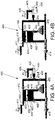
- the CVVH device 320 has a front panel 500 as shown in Figure 5 A and a back panel 505 as shown in Figure 5B .
- the front panel 500 includes a perfect fluid balance pump compartment 510, a negative fluid balance pump compartment 515, a stepper drive 520, a hemofilter 525, a replacement fluid bag 530 and a negative fluid balance bag 535.
- An inlet 540 is connected to the membrane oxygenator 315 of the ECMO system of Figure 3 while an outlet 545 is connected to the ECMO bladder 305 of Figure 3 .
- the CVVH device 320 can be mounted on a stand 580 with wheels for mobility.
- Stepper drive 520 is commercially available, manufactured by Parker Hannifin, model number VIX-250. It is contemplated that stepper drives other than the specific model identified herein may be utilized, so long as it performs the function of controlling the motion of the linear positioner.
- the perfect fluid balance pump compartment 510 houses a dual syringe-pump system 550, which includes a replacement fluid syringe 555, replacement fluid piston 556, a toxin clearance or ultrafiltration syringe 560, and toxin clearance or ultrafiltration piston 561.
- the pistons 556 and 561 are coupled to a translating arm 605, as shown in Figure 6 , which is a detailed illustration of the dual syringe-pump system 550.
- This syringe-pump system 550 is used to achieve a perfect fluid balance.
- the dual syringe-pump system 550 incorporated in the present invention consists of a pair of pistons 556 and 561 coupled to a single translating arm 605.
- the pistons 556 and 561 push or pull fluid in their respective syringes 555 and 560 (60cc syringe model 309653, BD, Franklin Lakes, NJ).
- Syringe 555 delivers replacement fluid while syringe 560 extracts the ultrafiltrate.
- This dual syringe-pump system 550 achieves a perfect fluid balance as the displacement of the translating arm 605 is identical for each piston while maintaining sterility as the replacement fluid and ultrafiltrate are stored in their respective syringes 555 and 560.
- the translating arm 605 is attached to a bearing truck (not shown) driven by a linear positioner 610 (LP28T0150-D01-G21-M1322-H3-L2, Parker Hannifin Corp., Cleveland, OH).
- the linear positioner 610 consists of a lead screw (not shown) and a stepper motor (not shown) programmed via a stepper drive 520 ( Figure 5A ) mounted on the front panel 500.
- the linear positioner 610 utilized in the embodiment illustrated is dimensioned to achieve up to four strokes per minute, resulting in a maximum flow rate of 8L/hour. It is contemplated that maximum allowable strokes per minute and thereby the maximum flow rate may be modified by altering the dimensions of the linear positioner 610.
- the negative fluid balance pump compartment 515 houses a singular syringe-pump system 564 having a negative fluid balance syringe 565 and a negative fluid balance piston 575.
- This singular syringe-pump system 564 extracts a portion of the replacement fluid in order to achieve a net negative fluid balance.
- the singular syringe-pump system 564 is mounted in-line with the dual syringe-pump system 550. The system 564 extracts replacement fluid before this fluid is delivered to the patient, thus reducing the overall replacement fluid flow rate while maintaining the same ultrafiltrate removal flow rate.
- the singular syringe-pump system 564 used in the present invention is shown.
- the system 564 has a negative fluid balance syringe 565 and a negative fluid balance piston 575.
- this singular piston-syringe system 564 is driven by a linear positioner 710 that consists of an identical lead screw (not shown) and stepper motor (not shown) programmed via a stepper drive 520 ( Figure 5A ) mounted on the front panel 500.
- the stepper drive 520 controls the motion of both piston-syringe systems 550 and 564.
- the compartments 510 and 515 can be enclosed in a transparent box with a hinged lid made of polycarbonate in order to allow for easy access.
- space is provided above the compartments 510 and 515 for the replacement fluid bag 530 and the negative fluid balance bag 535.
- These bags 530 and 535 can be placed in individual compartments as shown in Figure 5A , whereby the compartments for the bags have a transparent box containing a sliding drawer that accommodates a 1000 niL disposable bag (Viaflex bag, Baxter International Inc., Deerfield, IL).
- the present invention was designed as described herein to simplify the handling of the fluids and to ensure fluid sterility, as well as the sterility of the whole system.
- a replacement fluid bag 530 filled with replacement fluid is positioned in the CVVH device 320 and an empty negative fluid bag 535 is positioned in the CVVH device 320.
- the replacement fluid syringe 555 is filled with replacement fluid while the ultrafiltration or toxin clearance syringe 560 is mounted with its piston 561 pushed to its lowest position (i.e., minimum stroke position).
- the hemofilter 525 can be mounted vertically on the left side of the replacement fluid bag 530.
- Other components of the front panel 500 include tubing (high-purity medical grade silicone tubing, part# 51845K55, McMaster-Carr, Aurora, OH) for connecting the syringes and fluid bags to the stepper driver and three three-way pinch valves 585, 587, and 589 (100P3-MP12-05-S-F, Bio-Chem Valve Inc., Boonton, NJ) for controlling the path of each fluid from the syringes 555, 560, and 565 to the tubing network.
- the pinch valves chosen are designed such that there is no contact between the valve components and the fluid, thereby facilitating system sterility.
- pinch valve 585 connects the replacement fluid syringe 555 to either the hemofilter outlet or the replacement fluid bag 530.
- Pinch valve 587 connects the ultrafiltration or toxin clearance syringe 560 and either the ultrafiltrate port of the hemofilter or the ultrafiltrate clearance bag 590 shown in Figure 5B .
- Pinch valve 589 connects the negative fluid balance syringe 565 to either the tube connecting the replacement fluid syringe 555 to the hemofilter outlet or the negative fluid balance bag 535.
- the back panel 505 is designed to house the ultrafiltrate clearance bag 590.
- the ultrafiltrate clearance bag 590 can be housed in a compartment having a drawer for the bag 590.
- a 5000 mL disposable bag can be used for the collection of ultrafiltrate that is removed from the hemofilter 525 of Figure 5A .
- the first mode involves the dual syringe-pump system and the second mode involves the singular syringe-pump system.
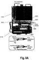
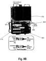
- FIGs 8A and 8B drawings showing the mechanisms involved in the production of a perfect fluid balance according to the present invention are illustrated.
- a perfect fluid balance is attained in two phases.
- Figure 8A represents the first phase.
- the first phase in the production of a perfect fluid balance consists of the delivery of replacement fluid and the extraction of ultrafiltrate.
- Two pinch valves 800 and 805 are involved in performing these functions.
- the first pinch valve 800 connects the replacement fluid syringe 810 to the filtered blood coming from the hemofilter 815.
- the second pinch valve 805 connects the ultrafiltrate coming from the hemofilter 815 to the ultrafiltration or toxin clearance syringe 820.
- the sensors mounted on the linear positioner, are utilized to transmit information reflecting the location of the linear positioner along the rail.
- the sensors are used to switch the pinch valves to different configurations. Each time the linear positioner reaches the end of the rail, the pinch valves are switched to their opposite state. If a first pinch valve is open, the second pinch valve is closed and if the second pinch valve is open the first pinch valve is closed.
- Figure 8B represents the second phase.
- the second phase in the production of a perfect fluid balance consists of refilling the replacement fluid syringe 810 and draining the ultrafiltration syringe 820.
- the first pinch valve 800 now connects the replacement fluid bag 840 to the replacement fluid syringe 810 and the second pinch valve 805 connects the ultrafiltration syringe 820 to the ultrafiltrate clearance bag located on the back panel (not shown) of the CVVH device.
- the empty replacement fluid syringe 810 refills with replacement fluid while the full ultrafiltration syringe 820 empties its toxin content into the ultrafiltrate clearance bag located on the back panel (not shown) of the CVVH device.
- the novel CVVH device is operated to achieve a perfect fluid balance, these two phases are all that is necessary to achieve that result. Once the two-phase cycle has ended, the system reinitializes to restart phase one.
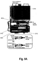
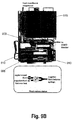
- FIGS 9A and 9B are drawings showing the mechanisms involved in the production of a negative fluid balance according to the present invention.
- the first phase occurs at the same time as the first phase in the production of a perfect fluid balance of Figure 8A .
- extra replacement fluid is removed and involves a third pinch valve 900 that connects the replacement fluid coming from the replacement fluid syringe 810 to the negative fluid balance syringe 905.
- Figure 9B represents the second phase.
- the third pinch valve 900 allows communication between the negative fluid balance syringe 905 and the negative fluid balance bag 915. Once the negative fluid balance syringe 905 is full, the syringe 905 empties its contents into the negative fluid balance bag 915. As the piston 910 reaches its minimum stroke, pinch valve 900 switches back to its initial state and the cycle is repeated.
- the present invention is a CVVH system 336 for use in patients that are not receiving ECMO.
- the CVVH circuit utilizes the same components as previously described in Figure 3B ; however the method of obtaining venous blood from the patient differs. Since the patient is not on ECMO, central venous access must be obtained with the use of a multiple lumen large bore intravenous dialysis catheter (not shown) 336.
- the CVVH system 304 is comprised of a patient with a standard dialysis access catheter 1010, a CVVH blood pump 335, and the novel CVVH device 320.
- a CVVH blood pump 335 blood is continuously drained from a patient's venous system through the venous lumen of the dialysis catheter 336.
- the force generated by the CVVH blood pump 335 is utilized to circulate the blood through the novel CVVH device 320.
- the novel CVVH device 320 is inserted in the venous lumen of the dialysis catheter 336 after the CVVH blood pump 335.
- CVVH device 320 Once the blood has been treated with CVVH device 320, it is returned into the arterial lumen of the dialysis catheter 336.
- the force generated by the CVVH blood pump 335 as well as the dual syringe pump system 550 subsequently returns the blood to the patient via the arterial lumen of the dialysis access catheter 336.
Claims (3)
- System (400) zur Regelung eins Fluids zur genauen kontinuierlichen venovenösen Hämofiltration umfassend(a) ein Hämofilter (416), das zum kontinuierlichen Filtern ungefilterten Blutes zur Extraktion eines Ultrafiltrates (415) ausgebildet ist, wodurch es zum Herstellen gefilterten Blutes ausgebildet ist,(b) einen ersten Behälter (420), der mit einem Ersatzfluid (410) gefüllt ist, wobei das Ersatzfluid (410) zur Überführung aus dem Behälter (420) in das gefilterte Blut vorgesehen ist,(c) einen zweiten Behälter (425) und den ersten Behälter (420), die mit einem Übersetzungsarm (402) verbunden sind, wobei der Übersetzungsarm (402) beweglich ausgebildet ist, um gleichzeitig dem Ersatzfluid (410) zu erlauben aus dem ersten Behälter (420) in das gefilterte Blut und dem Ultrafiltrat (415) aus dem Hämofilter (416) in den zweiten Behälter (425) überführt zu werden, wobei die Menge des Ersatzfluids (410) und des Ultrafiltrat (415) zueinander gleich ist,
gekennzeichnet durch(d) mindestens einen Sensor, der strukturell mit dem Übersetzungsarm (402) verbunden ist, um die relative Position des Übersetzungsarms (402) kontinuierlich zu überwachen, wodurch er ausgebildet ist zu bestimmen, ob ein Ersatzfluid (410) im ersten Behälter (411) und ein Ultrafiltrat (415) im zweiten Behälter (425) enthalten ist, und(e) Mittel, die ausgebildet sind zu veranlassen, dass der Übersetzungsarm stoppt und die Richtung wechselt, wenn der mindestens eine Sensor feststellt, dass der Übersetzungsarm (402) in Verbindung mit dem ersten Behälter (420) und dem zweiten Behälter (425) in einer Minimum- oder einer Maximumposition ist,wobei, in einer ersten Phase, der erste Behälter (420) zur Wiederbefüllung mit zusätzlichem Ersatzfluid (410) ausgebildet ist, zur gleichen Zeit wenn das Ultrafiltrat (415) zur Entleerung aus dem zweiten Behälter (425) vorgesehen ist, und
wobei, in einer zweiten Phase, das Ersatzfluid (410) zur Überführung aus dem ersten Behälter (420) vorgesehen ist, zur gleichen Zeit wenn das Ultrafiltrat (415) zur Extraktion aus dem Hämofilter (416) and zur Überführung in den zweiten Behälter (425) vorgesehen ist. - System nach Anspruch 1, ferner umfassend
einen dritten Behälter (435) zum Beinhalten eines Teils des Ersatzfluids (410), das zur Überführung aus dem ersten Behälter (420) in das gefilterte Blut vorgesehen ist, so dass der Teil des Ersatzfluids (410), der zur Überführung in den dritten Behälter (435) vorgesehen ist, nicht mit dem gefilterten Blut vermengt wird, wodurch eine negative Fluidbalance zwischen dem Ultrafiltrat (415), das zur Extraktion aus dem gefilterten Blut vorgesehen ist, und dem Ersatzfluid (410), das zur Überführung in das gefilterte Blut vorgesehen ist, hergestellt wird. - System nach Anspruch 1, dadurch gekennzeichnet, dass
die Mittel zum Veranlassen, dass der Übersetzungsarm (402) stoppt und die Richtung wechselt, ein Schrittantrieb (520) sind.
Applications Claiming Priority (2)
| Application Number | Priority Date | Filing Date | Title |
|---|---|---|---|
| US94221807P | 2007-06-06 | 2007-06-06 | |
| PCT/US2008/066108 WO2008154376A2 (en) | 2007-06-06 | 2008-06-06 | Novel fluid management system for accurate continuous hemofiltration in extracorporeal membrane oxygenation |
Publications (3)
| Publication Number | Publication Date |
|---|---|
| EP2155284A2 EP2155284A2 (de) | 2010-02-24 |
| EP2155284A4 EP2155284A4 (de) | 2015-10-28 |
| EP2155284B1 true EP2155284B1 (de) | 2018-10-17 |
Family
ID=40130450
Family Applications (1)
| Application Number | Title | Priority Date | Filing Date |
|---|---|---|---|
| EP08770325.2A Not-in-force EP2155284B1 (de) | 2007-06-06 | 2008-06-06 | Neues flüssigkeitsmanagementsystem für präzise kontinuierliche blutfiltrierung |
Country Status (6)
| Country | Link |
|---|---|
| US (1) | US8206594B2 (de) |
| EP (1) | EP2155284B1 (de) |
| JP (1) | JP2010528781A (de) |
| CA (1) | CA2724682A1 (de) |
| ES (1) | ES2705612T3 (de) |
| WO (1) | WO2008154376A2 (de) |
Families Citing this family (13)
| Publication number | Priority date | Publication date | Assignee | Title |
|---|---|---|---|---|
| USD669185S1 (en) * | 2009-11-12 | 2012-10-16 | Maquet Cardiopulmonary Ag | Medical device for extra-corporeal heart and/or lung support |
| US8821135B2 (en) | 2010-08-25 | 2014-09-02 | Emory University | Devices and systems for medical fluid treatment |
| US9211369B2 (en) | 2012-06-13 | 2015-12-15 | Ension, Inc | Compact integrated blood pump oxygenator or gas transfer device with hydrogel impeller packing material and rollover impeller outlet |
| DE102012110067A1 (de) | 2012-07-20 | 2014-05-15 | Hypower Gmbh | Verfahren und Vorrichtung zur Einstellung der Menge oder der Partialdrücke zweier Gase in einem Fluid |
| DE102013112523A1 (de) | 2013-11-14 | 2015-05-21 | Technische Universität Dresden | Verfahren und Vorrichtung zum Einstellen der Mengenanteile unterschiedlicher Gase in einer Flüssigkeit |
| ITUB20159161A1 (it) * | 2015-12-18 | 2017-06-18 | Eurosets Srl | Apparecchiatura per la decapneizzazione del sangue |
| ITUB20159389A1 (it) * | 2015-12-18 | 2017-06-18 | Eurosets Srl | Apparecchiatura per la decapneizzazione del sangue |
| WO2017218987A1 (en) | 2016-06-16 | 2017-12-21 | Ension, Inc. | Adult and pediatric extracorporeal life support system with heparin treated oxygenator surface and magnetic levitation motor |
| DE102017210134A1 (de) * | 2016-12-15 | 2018-06-21 | Fresenius Medical Care Deutschland Gmbh | System zur extrakorporalen Blutbehandlung, Behandlungsvorrichtung, Kit und Verfahren zum Betreiben eines Systems zur extrakorporalen Blutbehandlung |
| US10833570B2 (en) | 2017-12-22 | 2020-11-10 | Massachusetts Institute Of Technology | Homopolar bearingless slice motors |
| WO2021167614A1 (en) | 2020-02-20 | 2021-08-26 | First Pass, Llc | Manual clot aspiration and filtration system and method of removing a clot |
| WO2024009994A1 (ja) * | 2022-07-06 | 2024-01-11 | 株式会社ジェイ・エム・エス | 中間システム及び血液浄化システム |
| EP4353275A1 (de) | 2022-10-13 | 2024-04-17 | Gambro Lundia AB | Vorrichtung zur extrakorporalen blutbehandlung |
Family Cites Families (12)
| Publication number | Priority date | Publication date | Assignee | Title |
|---|---|---|---|---|
| DE2739350A1 (de) * | 1977-09-01 | 1979-03-15 | Schi Wa Arzneimittel | Vorrichtung zur behandlung uraemischer patienten |
| JPS56136566A (en) * | 1980-03-25 | 1981-10-24 | Daicel Ltd | Filtration type artificial kidney device |
| DE3801316A1 (de) * | 1987-01-20 | 1988-07-28 | Knoll Ag | Geraet zur behandlung uraemischer patienten |
| US5306510A (en) * | 1988-01-14 | 1994-04-26 | Cyberlab, Inc. | Automated pipetting system |
| DE4116178C1 (de) * | 1991-05-17 | 1992-11-12 | Fresenius Ag, 6380 Bad Homburg, De | |
| DE4220436A1 (de) * | 1992-06-25 | 1994-01-05 | Riggers Medizintechnik Thalhei | Gleitkolbenmeßeinrichtung zur Messung von Flußmengen, Ultrafiltrationsmengen und Ultrafiltrationsraten, insbesondere in Dialysemaschinen |
| US6852090B2 (en) * | 1997-02-14 | 2005-02-08 | Nxstage Medical, Inc. | Fluid processing systems and methods using extracorporeal fluid flow panels oriented within a cartridge |
| US20010016699A1 (en) * | 1997-02-14 | 2001-08-23 | Jeffrey H. Burbank | Hemofiltration system |
| CA2495561C (en) * | 2002-08-08 | 2008-11-18 | Asahi Kasei Medical Co., Ltd. | Blood purifying device and method of operating the same |
| US7029456B2 (en) * | 2003-10-15 | 2006-04-18 | Baxter International Inc. | Medical fluid therapy flow balancing and synchronization system |
| US7338461B2 (en) * | 2004-02-02 | 2008-03-04 | The General Hospital Corporation | Modified organ support devices |
| WO2006002151A1 (en) * | 2004-06-21 | 2006-01-05 | Hemolife Medical, Inc. | Plasma detoxification and volume control system and methods of use |
-
2008
- 2008-06-06 EP EP08770325.2A patent/EP2155284B1/de not_active Not-in-force
- 2008-06-06 WO PCT/US2008/066108 patent/WO2008154376A2/en active Application Filing
- 2008-06-06 ES ES08770325T patent/ES2705612T3/es active Active
- 2008-06-06 JP JP2010511362A patent/JP2010528781A/ja active Pending
- 2008-06-06 US US12/663,253 patent/US8206594B2/en active Active
- 2008-06-06 CA CA2724682A patent/CA2724682A1/en not_active Abandoned
Non-Patent Citations (1)
| Title |
|---|
| None * |
Also Published As
| Publication number | Publication date |
|---|---|
| WO2008154376A3 (en) | 2010-01-07 |
| EP2155284A2 (de) | 2010-02-24 |
| US20100288703A1 (en) | 2010-11-18 |
| US8206594B2 (en) | 2012-06-26 |
| JP2010528781A (ja) | 2010-08-26 |
| EP2155284A4 (de) | 2015-10-28 |
| WO2008154376A2 (en) | 2008-12-18 |
| ES2705612T3 (es) | 2019-03-26 |
| CA2724682A1 (en) | 2008-12-18 |
Similar Documents
| Publication | Publication Date | Title |
|---|---|---|
| EP2155284B1 (de) | Neues flüssigkeitsmanagementsystem für präzise kontinuierliche blutfiltrierung | |
| JP6869551B2 (ja) | 腹膜限外濾過を実行するための装置 | |
| JP6554476B2 (ja) | 腹膜限外濾過を実行するための方法および装置 | |
| US8562822B2 (en) | Dynamic weight balancing of flow in kidney failure treatment systems | |
| TW503097B (en) | Method and apparatus for monitoring and controlling peritoneal dialysis therapy | |
| US7311689B2 (en) | Method and apparatus for peripheral vein fluid removal in heart failure | |
| EP2739325B1 (de) | Hämodialysesystem mit einem durchflussweg mit gesteuertem nachgiebigem volumen | |
| JPS62500006A (ja) | 完全携帯式、半自動機械式心肺機能代行装置およびその方法 | |
| US20060030809A1 (en) | Apparatus and method for multiple organ assist | |
| Pstras et al. | Dialysis therapies: Investigation of transport and regulatory processes using mathematical modelling | |
| Stone Mountain | Fortenberry et al.(45) Date of Patent: Jun. 26, 2012 | |
| Blumenthal et al. | Inflow time and recirculation in single-needle hemodialysis | |
| EP4292623A1 (de) | Peritonealdialyseschaltung | |
| EP4157392B1 (de) | Peritonealdialyse unter verwendung eines unter druck stehenden zylinders | |
| US20240009365A1 (en) | Weight-based peritoneal dialysis system including a drain trolley | |
| Dasi | Philippe Sucosky | |
| WO2024081155A1 (en) | Peritoneal dialysis system using cylinder and optionally air pump | |
| Mason | The role of spontaneous and pumped haemofiltration | |
| Ronco et al. | Technical requirements for high volume hemofiltration |
Legal Events
| Date | Code | Title | Description |
|---|---|---|---|
| PUAI | Public reference made under article 153(3) epc to a published international application that has entered the european phase |
Free format text: ORIGINAL CODE: 0009012 |
|
| 17P | Request for examination filed |
Effective date: 20091203 |
|
| AK | Designated contracting states |
Kind code of ref document: A2 Designated state(s): AT BE BG CH CY CZ DE DK EE ES FI FR GB GR HR HU IE IS IT LI LT LU LV MC MT NL NO PL PT RO SE SI SK TR |
|
| AX | Request for extension of the european patent |
Extension state: AL BA MK RS |
|
| RIN1 | Information on inventor provided before grant (corrected) |
Inventor name: YOGANATHAN, AJIT, P. Inventor name: FORTENBERRY, JAMES, D. Inventor name: DASI, LAKSHMI, PRASAD Inventor name: SUCOSKY, PHILIPPE Inventor name: PADEN, MATTHEW, L. |
|
| DAX | Request for extension of the european patent (deleted) | ||
| RAP1 | Party data changed (applicant data changed or rights of an application transferred) |
Owner name: EMORY UNIVERSITY Owner name: GEORGIA TECH RESEARCH CORPORATION Owner name: CHILDREN'S HEALTH CARE OF ATLANTA |
|
| A4 | Supplementary search report drawn up and despatched |
Effective date: 20150924 |
|
| RIC1 | Information provided on ipc code assigned before grant |
Ipc: A61M 1/34 20060101AFI20150918BHEP |
|
| STAA | Information on the status of an ep patent application or granted ep patent |
Free format text: STATUS: EXAMINATION IS IN PROGRESS |
|
| 17Q | First examination report despatched |
Effective date: 20170830 |
|
| GRAP | Despatch of communication of intention to grant a patent |
Free format text: ORIGINAL CODE: EPIDOSNIGR1 |
|
| STAA | Information on the status of an ep patent application or granted ep patent |
Free format text: STATUS: GRANT OF PATENT IS INTENDED |
|
| INTG | Intention to grant announced |
Effective date: 20180511 |
|
| GRAS | Grant fee paid |
Free format text: ORIGINAL CODE: EPIDOSNIGR3 |
|
| GRAA | (expected) grant |
Free format text: ORIGINAL CODE: 0009210 |
|
| STAA | Information on the status of an ep patent application or granted ep patent |
Free format text: STATUS: THE PATENT HAS BEEN GRANTED |
|
| AK | Designated contracting states |
Kind code of ref document: B1 Designated state(s): AT BE BG CH CY CZ DE DK EE ES FI FR GB GR HR HU IE IS IT LI LT LU LV MC MT NL NO PL PT RO SE SI SK TR |
|
| REG | Reference to a national code |
Ref country code: GB Ref legal event code: FG4D |
|
| REG | Reference to a national code |
Ref country code: CH Ref legal event code: EP |
|
| REG | Reference to a national code |
Ref country code: IE Ref legal event code: FG4D |
|
| REG | Reference to a national code |
Ref country code: DE Ref legal event code: R096 Ref document number: 602008057468 Country of ref document: DE Ref country code: AT Ref legal event code: REF Ref document number: 1053250 Country of ref document: AT Kind code of ref document: T Effective date: 20181115 |
|
| REG | Reference to a national code |
Ref country code: NL Ref legal event code: MP Effective date: 20181017 |
|
| REG | Reference to a national code |
Ref country code: LT Ref legal event code: MG4D |
|
| REG | Reference to a national code |
Ref country code: AT Ref legal event code: MK05 Ref document number: 1053250 Country of ref document: AT Kind code of ref document: T Effective date: 20181017 |
|
| REG | Reference to a national code |
Ref country code: ES Ref legal event code: FG2A Ref document number: 2705612 Country of ref document: ES Kind code of ref document: T3 Effective date: 20190326 |
|
| PG25 | Lapsed in a contracting state [announced via postgrant information from national office to epo] |
Ref country code: NL Free format text: LAPSE BECAUSE OF FAILURE TO SUBMIT A TRANSLATION OF THE DESCRIPTION OR TO PAY THE FEE WITHIN THE PRESCRIBED TIME-LIMIT Effective date: 20181017 |
|
| PG25 | Lapsed in a contracting state [announced via postgrant information from national office to epo] |
Ref country code: AT Free format text: LAPSE BECAUSE OF FAILURE TO SUBMIT A TRANSLATION OF THE DESCRIPTION OR TO PAY THE FEE WITHIN THE PRESCRIBED TIME-LIMIT Effective date: 20181017 Ref country code: LV Free format text: LAPSE BECAUSE OF FAILURE TO SUBMIT A TRANSLATION OF THE DESCRIPTION OR TO PAY THE FEE WITHIN THE PRESCRIBED TIME-LIMIT Effective date: 20181017 Ref country code: PL Free format text: LAPSE BECAUSE OF FAILURE TO SUBMIT A TRANSLATION OF THE DESCRIPTION OR TO PAY THE FEE WITHIN THE PRESCRIBED TIME-LIMIT Effective date: 20181017 Ref country code: HR Free format text: LAPSE BECAUSE OF FAILURE TO SUBMIT A TRANSLATION OF THE DESCRIPTION OR TO PAY THE FEE WITHIN THE PRESCRIBED TIME-LIMIT Effective date: 20181017 Ref country code: FI Free format text: LAPSE BECAUSE OF FAILURE TO SUBMIT A TRANSLATION OF THE DESCRIPTION OR TO PAY THE FEE WITHIN THE PRESCRIBED TIME-LIMIT Effective date: 20181017 Ref country code: BG Free format text: LAPSE BECAUSE OF FAILURE TO SUBMIT A TRANSLATION OF THE DESCRIPTION OR TO PAY THE FEE WITHIN THE PRESCRIBED TIME-LIMIT Effective date: 20190117 Ref country code: NO Free format text: LAPSE BECAUSE OF FAILURE TO SUBMIT A TRANSLATION OF THE DESCRIPTION OR TO PAY THE FEE WITHIN THE PRESCRIBED TIME-LIMIT Effective date: 20190117 Ref country code: LT Free format text: LAPSE BECAUSE OF FAILURE TO SUBMIT A TRANSLATION OF THE DESCRIPTION OR TO PAY THE FEE WITHIN THE PRESCRIBED TIME-LIMIT Effective date: 20181017 Ref country code: IS Free format text: LAPSE BECAUSE OF FAILURE TO SUBMIT A TRANSLATION OF THE DESCRIPTION OR TO PAY THE FEE WITHIN THE PRESCRIBED TIME-LIMIT Effective date: 20190217 |
|
| PG25 | Lapsed in a contracting state [announced via postgrant information from national office to epo] |
Ref country code: GR Free format text: LAPSE BECAUSE OF FAILURE TO SUBMIT A TRANSLATION OF THE DESCRIPTION OR TO PAY THE FEE WITHIN THE PRESCRIBED TIME-LIMIT Effective date: 20190118 Ref country code: PT Free format text: LAPSE BECAUSE OF FAILURE TO SUBMIT A TRANSLATION OF THE DESCRIPTION OR TO PAY THE FEE WITHIN THE PRESCRIBED TIME-LIMIT Effective date: 20190217 Ref country code: SE Free format text: LAPSE BECAUSE OF FAILURE TO SUBMIT A TRANSLATION OF THE DESCRIPTION OR TO PAY THE FEE WITHIN THE PRESCRIBED TIME-LIMIT Effective date: 20181017 |
|
| REG | Reference to a national code |
Ref country code: DE Ref legal event code: R097 Ref document number: 602008057468 Country of ref document: DE |
|
| PG25 | Lapsed in a contracting state [announced via postgrant information from national office to epo] |
Ref country code: DK Free format text: LAPSE BECAUSE OF FAILURE TO SUBMIT A TRANSLATION OF THE DESCRIPTION OR TO PAY THE FEE WITHIN THE PRESCRIBED TIME-LIMIT Effective date: 20181017 Ref country code: CZ Free format text: LAPSE BECAUSE OF FAILURE TO SUBMIT A TRANSLATION OF THE DESCRIPTION OR TO PAY THE FEE WITHIN THE PRESCRIBED TIME-LIMIT Effective date: 20181017 |
|
| PGFP | Annual fee paid to national office [announced via postgrant information from national office to epo] |
Ref country code: IT Payment date: 20190620 Year of fee payment: 12 Ref country code: DE Payment date: 20190521 Year of fee payment: 12 |
|
| PLBE | No opposition filed within time limit |
Free format text: ORIGINAL CODE: 0009261 |
|
| STAA | Information on the status of an ep patent application or granted ep patent |
Free format text: STATUS: NO OPPOSITION FILED WITHIN TIME LIMIT |
|
| PG25 | Lapsed in a contracting state [announced via postgrant information from national office to epo] |
Ref country code: SK Free format text: LAPSE BECAUSE OF FAILURE TO SUBMIT A TRANSLATION OF THE DESCRIPTION OR TO PAY THE FEE WITHIN THE PRESCRIBED TIME-LIMIT Effective date: 20181017 Ref country code: EE Free format text: LAPSE BECAUSE OF FAILURE TO SUBMIT A TRANSLATION OF THE DESCRIPTION OR TO PAY THE FEE WITHIN THE PRESCRIBED TIME-LIMIT Effective date: 20181017 Ref country code: RO Free format text: LAPSE BECAUSE OF FAILURE TO SUBMIT A TRANSLATION OF THE DESCRIPTION OR TO PAY THE FEE WITHIN THE PRESCRIBED TIME-LIMIT Effective date: 20181017 |
|
| PGFP | Annual fee paid to national office [announced via postgrant information from national office to epo] |
Ref country code: FR Payment date: 20190510 Year of fee payment: 12 |
|
| 26N | No opposition filed |
Effective date: 20190718 |
|
| PG25 | Lapsed in a contracting state [announced via postgrant information from national office to epo] |
Ref country code: SI Free format text: LAPSE BECAUSE OF FAILURE TO SUBMIT A TRANSLATION OF THE DESCRIPTION OR TO PAY THE FEE WITHIN THE PRESCRIBED TIME-LIMIT Effective date: 20181017 |
|
| PGFP | Annual fee paid to national office [announced via postgrant information from national office to epo] |
Ref country code: ES Payment date: 20190701 Year of fee payment: 12 Ref country code: GB Payment date: 20190605 Year of fee payment: 12 |
|
| PG25 | Lapsed in a contracting state [announced via postgrant information from national office to epo] |
Ref country code: MC Free format text: LAPSE BECAUSE OF FAILURE TO SUBMIT A TRANSLATION OF THE DESCRIPTION OR TO PAY THE FEE WITHIN THE PRESCRIBED TIME-LIMIT Effective date: 20181017 |
|
| REG | Reference to a national code |
Ref country code: CH Ref legal event code: PL |
|
| REG | Reference to a national code |
Ref country code: BE Ref legal event code: MM Effective date: 20190630 |
|
| PG25 | Lapsed in a contracting state [announced via postgrant information from national office to epo] |
Ref country code: TR Free format text: LAPSE BECAUSE OF FAILURE TO SUBMIT A TRANSLATION OF THE DESCRIPTION OR TO PAY THE FEE WITHIN THE PRESCRIBED TIME-LIMIT Effective date: 20181017 |
|
| PG25 | Lapsed in a contracting state [announced via postgrant information from national office to epo] |
Ref country code: IE Free format text: LAPSE BECAUSE OF NON-PAYMENT OF DUE FEES Effective date: 20190606 |
|
| PG25 | Lapsed in a contracting state [announced via postgrant information from national office to epo] |
Ref country code: BE Free format text: LAPSE BECAUSE OF NON-PAYMENT OF DUE FEES Effective date: 20190630 Ref country code: LI Free format text: LAPSE BECAUSE OF NON-PAYMENT OF DUE FEES Effective date: 20190630 Ref country code: CH Free format text: LAPSE BECAUSE OF NON-PAYMENT OF DUE FEES Effective date: 20190630 Ref country code: LU Free format text: LAPSE BECAUSE OF NON-PAYMENT OF DUE FEES Effective date: 20190606 |
|
| REG | Reference to a national code |
Ref country code: DE Ref legal event code: R119 Ref document number: 602008057468 Country of ref document: DE |
|
| GBPC | Gb: european patent ceased through non-payment of renewal fee |
Effective date: 20200606 |
|
| PG25 | Lapsed in a contracting state [announced via postgrant information from national office to epo] |
Ref country code: FR Free format text: LAPSE BECAUSE OF NON-PAYMENT OF DUE FEES Effective date: 20200630 Ref country code: GB Free format text: LAPSE BECAUSE OF NON-PAYMENT OF DUE FEES Effective date: 20200606 |
|
| PG25 | Lapsed in a contracting state [announced via postgrant information from national office to epo] |
Ref country code: DE Free format text: LAPSE BECAUSE OF NON-PAYMENT OF DUE FEES Effective date: 20210101 Ref country code: CY Free format text: LAPSE BECAUSE OF FAILURE TO SUBMIT A TRANSLATION OF THE DESCRIPTION OR TO PAY THE FEE WITHIN THE PRESCRIBED TIME-LIMIT Effective date: 20181017 |
|
| PG25 | Lapsed in a contracting state [announced via postgrant information from national office to epo] |
Ref country code: MT Free format text: LAPSE BECAUSE OF FAILURE TO SUBMIT A TRANSLATION OF THE DESCRIPTION OR TO PAY THE FEE WITHIN THE PRESCRIBED TIME-LIMIT Effective date: 20181017 Ref country code: HU Free format text: LAPSE BECAUSE OF FAILURE TO SUBMIT A TRANSLATION OF THE DESCRIPTION OR TO PAY THE FEE WITHIN THE PRESCRIBED TIME-LIMIT; INVALID AB INITIO Effective date: 20080606 |
|
| PG25 | Lapsed in a contracting state [announced via postgrant information from national office to epo] |
Ref country code: IT Free format text: LAPSE BECAUSE OF NON-PAYMENT OF DUE FEES Effective date: 20200606 |
|
| REG | Reference to a national code |
Ref country code: ES Ref legal event code: FD2A Effective date: 20211102 |
|
| PG25 | Lapsed in a contracting state [announced via postgrant information from national office to epo] |
Ref country code: ES Free format text: LAPSE BECAUSE OF NON-PAYMENT OF DUE FEES Effective date: 20200607 |