EP2155120B1 - Chirurgisch implantierbare knieprothese mit erfasstem kiel - Google Patents
Chirurgisch implantierbare knieprothese mit erfasstem kiel Download PDFInfo
- Publication number
- EP2155120B1 EP2155120B1 EP08755543.9A EP08755543A EP2155120B1 EP 2155120 B1 EP2155120 B1 EP 2155120B1 EP 08755543 A EP08755543 A EP 08755543A EP 2155120 B1 EP2155120 B1 EP 2155120B1
- Authority
- EP
- European Patent Office
- Prior art keywords
- keel
- prosthesis
- posterior
- prosthesis according
- anterior
- Prior art date
- Legal status (The legal status is an assumption and is not a legal conclusion. Google has not performed a legal analysis and makes no representation as to the accuracy of the status listed.)
- Active
Links
Images


Classifications
-
- A—HUMAN NECESSITIES
- A61—MEDICAL OR VETERINARY SCIENCE; HYGIENE
- A61F—FILTERS IMPLANTABLE INTO BLOOD VESSELS; PROSTHESES; DEVICES PROVIDING PATENCY TO, OR PREVENTING COLLAPSING OF, TUBULAR STRUCTURES OF THE BODY, e.g. STENTS; ORTHOPAEDIC, NURSING OR CONTRACEPTIVE DEVICES; FOMENTATION; TREATMENT OR PROTECTION OF EYES OR EARS; BANDAGES, DRESSINGS OR ABSORBENT PADS; FIRST-AID KITS
- A61F2/00—Filters implantable into blood vessels; Prostheses, i.e. artificial substitutes or replacements for parts of the body; Appliances for connecting them with the body; Devices providing patency to, or preventing collapsing of, tubular structures of the body, e.g. stents
- A61F2/02—Prostheses implantable into the body
- A61F2/30—Joints
- A61F2/38—Joints for elbows or knees
- A61F2/389—Tibial components
-
- A—HUMAN NECESSITIES
- A61—MEDICAL OR VETERINARY SCIENCE; HYGIENE
- A61F—FILTERS IMPLANTABLE INTO BLOOD VESSELS; PROSTHESES; DEVICES PROVIDING PATENCY TO, OR PREVENTING COLLAPSING OF, TUBULAR STRUCTURES OF THE BODY, e.g. STENTS; ORTHOPAEDIC, NURSING OR CONTRACEPTIVE DEVICES; FOMENTATION; TREATMENT OR PROTECTION OF EYES OR EARS; BANDAGES, DRESSINGS OR ABSORBENT PADS; FIRST-AID KITS
- A61F2/00—Filters implantable into blood vessels; Prostheses, i.e. artificial substitutes or replacements for parts of the body; Appliances for connecting them with the body; Devices providing patency to, or preventing collapsing of, tubular structures of the body, e.g. stents
- A61F2/02—Prostheses implantable into the body
- A61F2/30—Joints
- A61F2/38—Joints for elbows or knees
- A61F2/3836—Special connection between upper and lower leg, e.g. constrained
-
- A—HUMAN NECESSITIES
- A61—MEDICAL OR VETERINARY SCIENCE; HYGIENE
- A61F—FILTERS IMPLANTABLE INTO BLOOD VESSELS; PROSTHESES; DEVICES PROVIDING PATENCY TO, OR PREVENTING COLLAPSING OF, TUBULAR STRUCTURES OF THE BODY, e.g. STENTS; ORTHOPAEDIC, NURSING OR CONTRACEPTIVE DEVICES; FOMENTATION; TREATMENT OR PROTECTION OF EYES OR EARS; BANDAGES, DRESSINGS OR ABSORBENT PADS; FIRST-AID KITS
- A61F2/00—Filters implantable into blood vessels; Prostheses, i.e. artificial substitutes or replacements for parts of the body; Appliances for connecting them with the body; Devices providing patency to, or preventing collapsing of, tubular structures of the body, e.g. stents
- A61F2/02—Prostheses implantable into the body
- A61F2/30—Joints
- A61F2/38—Joints for elbows or knees
- A61F2/3886—Joints for elbows or knees for stabilising knees against anterior or lateral dislocations
-
- A—HUMAN NECESSITIES
- A61—MEDICAL OR VETERINARY SCIENCE; HYGIENE
- A61F—FILTERS IMPLANTABLE INTO BLOOD VESSELS; PROSTHESES; DEVICES PROVIDING PATENCY TO, OR PREVENTING COLLAPSING OF, TUBULAR STRUCTURES OF THE BODY, e.g. STENTS; ORTHOPAEDIC, NURSING OR CONTRACEPTIVE DEVICES; FOMENTATION; TREATMENT OR PROTECTION OF EYES OR EARS; BANDAGES, DRESSINGS OR ABSORBENT PADS; FIRST-AID KITS
- A61F2/00—Filters implantable into blood vessels; Prostheses, i.e. artificial substitutes or replacements for parts of the body; Appliances for connecting them with the body; Devices providing patency to, or preventing collapsing of, tubular structures of the body, e.g. stents
- A61F2/02—Prostheses implantable into the body
- A61F2/30—Joints
- A61F2002/30001—Additional features of subject-matter classified in A61F2/28, A61F2/30 and subgroups thereof
- A61F2002/30108—Shapes
- A61F2002/3011—Cross-sections or two-dimensional shapes
- A61F2002/30112—Rounded shapes, e.g. with rounded corners
- A61F2002/30125—Rounded shapes, e.g. with rounded corners elliptical or oval
-
- A—HUMAN NECESSITIES
- A61—MEDICAL OR VETERINARY SCIENCE; HYGIENE
- A61F—FILTERS IMPLANTABLE INTO BLOOD VESSELS; PROSTHESES; DEVICES PROVIDING PATENCY TO, OR PREVENTING COLLAPSING OF, TUBULAR STRUCTURES OF THE BODY, e.g. STENTS; ORTHOPAEDIC, NURSING OR CONTRACEPTIVE DEVICES; FOMENTATION; TREATMENT OR PROTECTION OF EYES OR EARS; BANDAGES, DRESSINGS OR ABSORBENT PADS; FIRST-AID KITS
- A61F2/00—Filters implantable into blood vessels; Prostheses, i.e. artificial substitutes or replacements for parts of the body; Appliances for connecting them with the body; Devices providing patency to, or preventing collapsing of, tubular structures of the body, e.g. stents
- A61F2/02—Prostheses implantable into the body
- A61F2/30—Joints
- A61F2/30767—Special external or bone-contacting surface, e.g. coating for improving bone ingrowth
- A61F2/30771—Special external or bone-contacting surface, e.g. coating for improving bone ingrowth applied in original prostheses, e.g. holes or grooves
- A61F2002/30878—Special external or bone-contacting surface, e.g. coating for improving bone ingrowth applied in original prostheses, e.g. holes or grooves with non-sharp protrusions, for instance contacting the bone for anchoring, e.g. keels, pegs, pins, posts, shanks, stems, struts
- A61F2002/30884—Fins or wings, e.g. longitudinal wings for preventing rotation within the bone cavity
-
- A—HUMAN NECESSITIES
- A61—MEDICAL OR VETERINARY SCIENCE; HYGIENE
- A61F—FILTERS IMPLANTABLE INTO BLOOD VESSELS; PROSTHESES; DEVICES PROVIDING PATENCY TO, OR PREVENTING COLLAPSING OF, TUBULAR STRUCTURES OF THE BODY, e.g. STENTS; ORTHOPAEDIC, NURSING OR CONTRACEPTIVE DEVICES; FOMENTATION; TREATMENT OR PROTECTION OF EYES OR EARS; BANDAGES, DRESSINGS OR ABSORBENT PADS; FIRST-AID KITS
- A61F2/00—Filters implantable into blood vessels; Prostheses, i.e. artificial substitutes or replacements for parts of the body; Appliances for connecting them with the body; Devices providing patency to, or preventing collapsing of, tubular structures of the body, e.g. stents
- A61F2/02—Prostheses implantable into the body
- A61F2/30—Joints
- A61F2/38—Joints for elbows or knees
- A61F2002/3895—Joints for elbows or knees unicompartimental
Definitions
- This invention relates to a prosthesis which is surgically implantable into a body joint, such as the knee.
- this area of exposed bone is 2-3 mm below the area of existing eroded bone surface and generally requires removal of the entire subchondral bone in the area of implant location.
- SC subchondral bone of the tibial plateau, which is attached to the remaining articular surface, is removed as standard practice for both the total knee (TKR) and partial or unicompartmental knee (UKR) replacement procedures.
- PE polyethylene
- tibial plateau generally greater than 7 mm.
- the subchondral bone thickness on a typical tibial plateau is generally 2-3 mm.
- a typical TKR or UKR implant will require resection of the entire SC bone present on the tibial plateau, leaving only cancellous bone.
- the PE is typically held in place by an interference fit or by melt infusion to a metal backing plate known as the tibial baseplate.
- This baseplate is held in place on the now exposed cancellous bone of the tibia by screws, keels, posts, or combinations of some or all of these devices.
- the screws and keels generally provide immediate fixation, but these are usually enhanced by the addition of the PMMA cement.
- perforated keels, tapered and hourglass shaped posts when these projections are set in uncured cement, the cement forms around and through them and, once hardened, provides an almost indestructible bond between the PMMA cement and the tibial baseplate.
- the cement also permeates the open cellular structure of the cancellous bone, thus resulting in the same type of bond between the bone and the tibial baseplate.
- the metal tibial baseplate is not used and an all-PE design is bonded directly to the cancellous bone with the PMMA cement utilizing a roughened PE surface or molded posts to facilitate the bond with the PMMA cement.
- THA tibial hemiarthroplasty
- Previous keel designs whether utilized for THA, UKR, or TKR implants, typically utilize an anteriorly-oriented keel.
- the Zimmer Sbarbaro "skate" implant has a keel aligned in the anterior-posterior (AP) direction, with the posterior portion being rounded and sharpened and the anterior portion having an anterior (forward) pointing distal tip.
- AP anterior-posterior
- the length of the saw cut needed to insert the bottommost portion of the keel would be significantly longer the length of the keel at the base of the implant, thus allowing the implant to be able to slide in an anterior fashion upon implantation in an anterior to posterior insertion direction.
- keel which extends the majority of the length of the baseplate.
- the keel also comprises an hourglass shape in medial-lateral (ML) section. Due to the length of the keel and the hourglass design along its length, this implant cannot be inserted into the tibia without first making a substantial femoral cut to provide access to the tibia, or otherwise inserting the implant via a lengthwise insertion from the most anterior portion of the tibial plateau.
- ML medial-lateral
- the tibial plateau rather than receiving a simple angle saw cut in order to receive the implant, must have a milled hourglass shape cut in the plateau which extends through the most anterior cortical bone in order for the keel to be inserted into the joint. If such a milled cut is not prepared, then a cut equal to the largest width of the keel must be made, which would not provide positive locking with the keel unless a mantle of cement is used.
- US2007/0100462 describes known joint arthroplasty devices.
- EP1136045 describes a known prosthesis with a securing flange.
- FR2738739 describes a single-cotylar sliding knee joint replacement prosthesis.
- the present invention is defined in claim 1.
- the present invention includes a prosthesis with a captured keel design which provides for positive interlocking that resists unintended dislodgement of the implant without the need for PMMA cement.
- the prosthesis according to the present invention may be used in conjunction with a tibial preparation that removes much of the remaining cartilage but leaves the majority of the SC bone of the tibial plateau intact.
- the keel disclosed herein is differentiated from prior keel designs and incorporates a notched, angled, or other design wherein the most distal, posterior portion of the keel may extend more posteriorly than the most proximal, posterior portion of the keel, thus providing a keel shape of negative draft.
- the distal end of the keel may be longer in an AP direction than the proximal end of the keel, giving a recessed or hooked appearance.
- the keel may be of sufficient depth such that while the bottom of the prosthesis sits predominantly on the existing SC bone, the extended portion of the keel may reach below the underside of the SC bone, thus capturing the prosthesis with the remaining SC bone.
- the risk over time of prosthesis subsidence into the tibia may be largely eliminated. This may be of great significance to patients who have unicompartmental disease but are contra-indicated for UKR or TKR procedures because of gross obesity. Further, unlike other THA implants, the captured keel prosthesis according to the present invention may provide for significantly reduced motion against the tibia because of the interlocking keel design.
- One function of the prosthesis according to the present invention may be to effectively replace the articular material that has been lost due to the effects of osteoarthritis by spanning the diseased area and supporting the prosthesis by intimate contact with the surrounding healthy tissue.
- An advantage of this approach is that the combination of removing healthy articular material and replacing that same material with the prosthesis allows for a minimal thickness prosthesis to be utilized which does not need to disturb the meniscal function or location. This approach may result in an area under the prosthesis where the prosthesis is barely in contact with the area of osteoarthritis (where SC bone has been deformed or eburnated).
- the prosthesis according to the present invention may not disturb SC bone, thus reducing the chance of any prosthesis subsidence into cancellous bone like a UKR baseplate often does.
- the tibial plateau may have an absolutely flat surface after surgical preparation. Rather, the majority of the plateau, once the remaining articular material has been largely removed, may provide an adequate peripheral shoulder on which the prosthesis can be supported. Thus, if the area of the osteoarthritis defect were still lower than the SC bone once the majority of the plateau has been flattened, the prosthesis may simply bridge this area while the keel may pass through the defect to the underside of the SC bone in that area, providing an interlocking behavior.
- the keel of the prosthesis according to the present invention is arranged to be at least partially received within a cut prepared on the tibial plateau.
- the tibial cut may be of a size substantially equal to the size of a proximal end of the keel right underneath the prosthesis, such that little or no give exists between the tibial cut and keel, such that use of cement may be avoided.
- the desired location and size of the tibial cut may be matched with a particular prosthesis selected from a library of prostheses having different locations and sizes of keels.
- the tibial cut may be prepared with an appropriate milling device or the like which may be accurately located via temporary fixation, computer guidance, or other means.
- the surgical procedure may involve resection (flattening) of the remaining articular material on the tibial plateau in the area where the prosthesis will reside using an oscillating saw or other tool, sizing the plateau for the proper length, width and thickness and, utilizing a cutting guide, making a saw or rasp cut at the proper angle and direction with the oscillating saw.
- This vertical saw cut may ultimately determine the final position of the prosthesis.
- the keel of the prosthesis may be positioned into the guided saw cut location with the knee flexed and once in position, gently hammered into place.
- the prosthesis does not require femoral resection to implant.
- prosthesis is shown and described herein as being implanted in a knee joint, specifically as a unicompartmental knee prosthesis implantable in a knee joint between a femoral condyle and a corresponding tibial plateau, it is understood that the prosthesis could be utilized in joints other than the knee such as, but not limited to, the hip, shoulder, wrist, ankle, or elbow, or other small joints of the foot or hand.
- the prosthesis according to the present invention comprises a body 12 which is generally elliptical and which includes a bottom, or tibial, face 14 and an opposed top, or femoral, face 16.
- Body 12 includes an anterior end 18 and a posterior end 20, corresponding to the anatomical location of these ends 18, 20 of body 12 upon implantation into the knee joint, wherein the prosthesis shape may generally cover the majority of the medial or lateral tibial plateau T.
- a keel 22 is provided on the bottom face 14, and has an AP orientation as depicted herein.
- the keel 22 can have any location on the bottom face 14 and can be of any size suitable for insertion.
- Keel 22 has an anterior end 24 and a posterior end 26, again according to the anatomical location of these ends 24, 26 upon implantation.
- Keel posterior end 26 includes a distal posterior portion 28 that extends farther toward the body posterior end 20 compared with a proximal posterior portion 30 of the keel posterior end 26, creating a posterior keel design which is relieved, undercut, hooked, or similar.
- the keel designs according to the present invention provide inherent stability to the prosthesis 10 because femoral loading on the prosthesis 10 cannot reproduce motion of the prosthesis 10 required to dislodge it from the tibial plateau T. In addition to the embodiments depicted herein, it is understood that any keel having a distal posterior portion extending further toward the body posterior end than does the proximal posterior portion of the keel is fully contemplated according to the present invention.
- the top face 16 could be of uniform shape or could have a combination of sloped and flat surfaces.
- the entire top face 16 or portions thereof may range from generally convex to generally concave or combinations of those surfaces, and range from generally conformal to non-conformal, depending on the compartment for implantation, the condition of the ligaments and other soft tissue structure at the time of surgery, and how much stability the knee will require.
- the femoral face 16 shape may be characterized as an aspect ratio defined by the chord line and the thickness above or below this chord line as a function of distance from a defined point on the chord line, such as the leading edge or midpoint, much like an airfoil can be described. It is understood that the terms "concave” and “convex” as used herein are not restricted to describing surfaces with a constant radius of curvature, but rather are used to denote the general appearance of the surface.
- the remainder of the bottom face 14, excluding the keel 22, may include, for example, a generally flat surface which does not require “seating.”
- the bottom face 14 may be generally concave, flat, or convex, or anywhere within the range from concave to convex or combinations of those surfaces.
- concave and convex as used herein is not restricted to describing a surface with a constant radius of curvature, but rather is used to denote the general appearance of the surface.
- the body 12 further includes a peripheral edge 32 extending between the bottom face 14 and the top face 16. Edges along the periphery of the prosthesis 10 can be rounded. Any thickness of the prosthesis 10 or variation of thickness within the prosthesis 10 may be utilized, and may be determined so as to provide proper joint tensioning throughout the range of motion of the knee.
- the prosthesis 10 according to the present invention may have length and width proportions roughly similar to any of the current UKR tibial base plates, whereas its thickness may generally be 2-3 mm less than the UKR overall baseplate/PE thickness since the SC bone is not being removed. Of course, prosthesis 10 is not limited to these dimensions.
- the prosthesis 10 according to the present invention may be used in conjunction with the remaining meniscus or meniscal replacement by having a relieved thickness along the periphery where the meniscus is located. Additionally, the posterior end 20 of the femoral face 16 may be tapered, and two different femoral and tibial surface profiles utilized. Thinning of the posterior end 20 may be helpful in deep flexion to eliminate a lever which could tip the prosthesis 10 upward and potentially out of engagement with the tibial plateau T, and also to relieve possible impingement and pain.
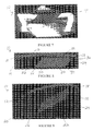
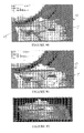
- a prosthesis 10 is depicted including a keel 22 with anterior and posterior ends 24, 26 which are angled toward the body posterior end 20 such that the distal posterior portion 28 of the keel 22 extends farther toward the body posterior end 20 compared with the proximal posterior portion 30 of the keel 22.
- Insertion of the prosthesis 10 may be facilitated by rounding of a distal anterior portion 34 of the keel as shown in FIGS. 3-4 , or rounding of both the distal anterior 34 and distal posterior portions 28 of the keel 22 as depicted in FIGS. 5-7 .
- solely the distal posterior portion 28 of the keel may be rounded.
- keel 22 may have different lengths along tibial face 14 and be positioned differently on tibial face 14.
- FIG. 5 depicts a keel 22 according to the invention having a length that extends along half the length of the tibial face 14, positioned toward body anterior end 18, whereas FIG. 6 depicts a keel 22 having a length that extends along approximately 20% of the length of the tibial face 14.
- any length, depth, and positioning of keel 22 with respect to tibial face 14 is fully contemplated.
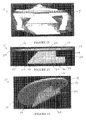
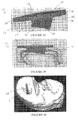
- FIGS. 8-10 depict a prosthesis including a keel with an angled posterior end 26 and chamfered distal anterior portion 34.
- FIGS. 17-25 illustrate keel embodiments according to the present invention wherein the keel posterior end 26 includes a notched or step-shaped configuration, such as to form an approximately 90° angle at the keel posterior end 26, and the keel anterior end 24 is angled, rounded, chamfered, or a combination thereof
- the keel 22 in addition to the angled posterior end 26 described above, could also incorporate an oppositely angled, notched, or step-shaped anterior end 24 wherein the keel anterior end 24 includes a proximal anterior portion 36 that extends farther toward the body anterior end 18 compared with a distal anterior portion 34 of the keel anterior end 24.
- the prosthesis 10 may be secured both anteriorly and posteriorly to preventing tipping or accidental dislodgement of the prosthesis 10.
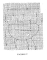
- FIGS. 26-27 a prosthesis 10 is illustrated with generic keel dimensions for a left medial knee prosthesis.
- the keel position may be described as a percentage of the length ahead of or behind the prosthesis centerline.
- the depth may be measured at the longest point as measured from the bottom face 14 of the prosthesis 10.
- a relationship table for the dimensions shown is provided below, where it is understood a change in these ratios by +/- 25% or more is fully contemplated.
- FIGS. 28-29 illustrate possible dimensions for an exemplary prosthesis according to the present invention having a 49 mm length and 2 mm thickness. It is understood, of course, that the prosthesis 10 is not limited to this configuration.
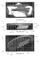
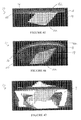
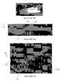
- FIGS. 30-34 illustrate a prosthesis 10 including a keel 22 with a hooked posterior end 26 and a relatively longer, angled anterior end 24 such that the keel anterior end 24 extends longer distally compared with the keel posterior end 26.
- FIG. 35 is a top perspective view of a tibial cut 68 which may be utilized for receiving the prosthesis 10 of FIG. 30 .
- FIGS. 39-41 depict a prosthesis 10 including a keel 22 with an angled posterior end 26 and a relatively shorter, rounded anterior end 24, such that the keel posterior end 26 extends longer distally compared with the keel anterior end 24.
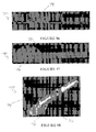
- the keel 22 in any embodiment depicted herein may taper in width from an end proximal to the prosthesis bottom face 14 to an end distal from the prosthesis bottom face 14 such that a proximal end 38 of the keel 22 is wider than a distal end 40 of the keel 22, creating a sort of knife edge which may facilitate insertion.
- a thinner prosthesis may be used where the final intent is to cover at least one face of the base prosthesis with a load-absorbing, cushioning, or other surfacing component 42.
- a hard articulating surface bearing material like metal, ceramic, or certain polymers (e.g., pyrolytic carbon or PEEK) which may include a surfacing component 42 provided on a bottom face 14 thereof wherein the surfacing component 42 then contacts the tibial plateau T, or alternatively is sandwiched between the outer articulating surface and an anchoring implant base.
- the load absorbing material may be a polymer or other material, such as a metallic sponge or springs.
- Biologically compatible urethanes, various hydrogels, and/or polymers that contain biologic components can also be utilized. It is also possible that one material can perform both the articulating function and the load absorbing function.
- the prosthesis configuration may allow for volume expansion of the surfacing component 42 while under load.
- the prosthesis 10 and the surfacing component 42 may be mechanically linked at the time of surgery to allow for surgeon selection of polymer thickness and material properties such as water content, durometer, viscoelastic behavior, and others. However, such a linkage is not necessary.
- a prosthesis 10 which includes a load absorbing or cushioning component 42 on a top face 16 thereof.
- a surface of the prosthesis 10 may be prepared mechanically and/or chemically to receive the load absorbing component 42.
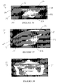
- FIG. 48 illustrates a bottom perspective view of a cushioning component 42 according to the present invention
- FIG. 49 illustrates a top perspective view of a top face 16 of the prosthesis of FIG. 45 which is prepared to receive a cushioning component 42 thereon.
- the keel 22 itself could have a load absorbing or cushioning component associated therewith, such as to provide strain isolation.
- a prosthesis 10 according to an example present only to assist in the understanding of the invention is illustrated which may be utilized for a lateral compartment implantation.
- the prosthesis depicted includes a keel 22 having an angled posterior end 26 and a relatively longer, angled anterior end 24, although any of the keel 22 embodiments shown or described herein could alternatively be utilized.
- a posterior slope 44 may be provided on both the femoral and tibial faces 14, 16 of the prosthesis 10.
- the prosthesis 10 according to the present invention may also include a cross-keel 46 provided generally in the medial-lateral (ML) direction, wherein cross-keel 46 may have a shorter length in the ML direction than does keel 22 in the AP direction. Such a cross-keel 46 may enhance the stability of the prosthesis 10 once inserted.
- the cross-keel 46 may be generally rectangular in shape, but is not limited as such. FIGS.
- cross-keel member 46 has an angle which is similar to the angle of the keel posterior end 26, wherein a distal portion 48 of the cross-keel 46 extends farther toward the body posterior end 20 compared with a proximal portion 50 of the cross-keel 46.
- other depths and orientations of cross-keel 46 as compared with keel 22 are also contemplated.
- FIGS. 59-60 depict a prosthesis 10 including a keel 22 with an angled posterior end 26, a rounded anterior end 24, and an angled cross-keel 46 extending to approximately the same distal depth as the keel 22.
- FIGS. 61-62 illustrate a prosthesis 10 according to an example present only to assist in the understanding of the invention including a keel 22 with an angled posterior end 26, a rounded anterior end 24, and a cross-keel member 46 extending along the depth of the keel 22 generally orthogonal to the prosthesis bottom face 14.
- FIGS. 65-66 illustrate a prosthesis 10 according to an example present only to assist in the understanding of the invention including a keel 22 with an angled posterior end 26, an anterior end 24 extending distally generally orthogonal to bottom face 14, and a cross-keel member 46 extending along the depth of the keel 22 at the anterior end 24 generally orthogonal to the prosthesis bottom face 14.
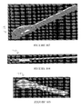
- the prosthesis 10 according to the present invention may also include shorter cross-keels or barb members 52 protruding from keel 22 generally in the ML direction.
- FIGS. 67-70 illustrate a prosthesis 10 including a keel 22 with an angled posterior end 26, a rounded, angled anterior end 24, and a plurality of angled barb members 52 having an orientation generally orthogonal to the angle of the posterior end 26, where each barb member 52 has a distal portion 54 that extends farther toward the body anterior end 18 compared with a proximal portion 56 of the barb member 52.
- Barb members 52 may be tapered such that an end 58 adjacent the keel 22 is wider compared with an end 60 removed from the keel 22.
- a single angled barb member 52 may be utilized as in FIGS. 71-77 .
- the prosthesis 10 may include a keel 22 with a hooked posterior end 26 and a rounded, angled anterior end 24, although it is understood that barb members 52 may be used with any keel design shown or described herein.
- the keel 22 may taper so as to be more narrow at an end 40 thereof distal from the prosthesis bottom face 14 such that the bottommost portion of the keel 22 may be sharpened, which may be helpful in the downward and backward motion used to insert the prosthesis 10.
- the hooked posterior end 26 may also taper to a three-sided point. This configuration may help facilitate securing the prosthesis 10 and capturing SC bone.
- the more proximal portion 30 of the posterior end 26 may remain flat in order to avoid an upward cutting capability of the prosthesis 10 once inserted.
- FIGS. 78-80 illustrate a prosthesis 10 including a posterior tab 62 provided at body posterior end 20 and extending distally beyond tibial face 14 which may be used to provide further stability to the prosthesis 10 once seated on the tibial plateau T.
- the posterior tab 62 may have any shape or depth suitable for implantation, and is not limited to the configuration depicted herein.
- the location of the keel on the prosthesis, the angle of the keel, and the overall length and/or depth of the keel may determine the allowable insertion angle and thus the overall thickness of the prosthesis, where too large a keel or too posterior a keel location may prevent insertion of the prosthesis.
- a deformable keel 22 could be utilized.
- a short depth (e.g., 2-3 mm) keel 22 could be used. In this case, once the prosthesis 10 is located in position, screws may be placed down through the interior of the keel 22 for final fixation.
- a keel that is integral with the prosthesis body may be limited in length due to insertion issues.
- a post or screw may be added to the prosthesis, such as by threading it through the prosthesis body, once the prosthesis is in position.
- "Captured" screws have a lower tapered threaded portion for grabbing the bone and an upper portion with a machined thread for attaching to the prosthesis body during the last portion of travel of the screw into the bone, allowing for additional stability for the prosthesis.
- Strain isolation bushings may be added between the prosthesis and the screw to further isolate the screw from any strain induced by micromotion of the prosthesis.
- the prosthesis 10 may include an expandable keel portion 64 such as, but not limited to, an anterior portion as depicted in FIGS. 81-82 .
- a push pin or other actuator could be advanced through an internal slot in the prosthesis 10 to flare out the expandable keel portion 64 in the ML direction for additional capture as depicted in FIGS. 83-84 .
- portions of the keel 22, especially those portions that will ultimately reside in cancellous bone, can be coated to promote bony in-growth or left smooth to discourage it.
- the keel 22 may include one or more openings therein.
- the prosthesis 10 according to the present invention could be screwed in, or have any type of fixation (e.g., cement) for additional stability.
- fixation e.g., cement
- a screw 66 or other fastener may be provided at the anterior-lateral corner of the prosthesis 10, and may be angled roughly 30 degrees downward off of the plane of the tibial plateau and 30 degrees from the AP direction of the keel 22, laterally (towards the tibial eminence).
- a screw or screws 66 are not limited to this position or orientation with respect to the prosthesis 10.
- FIG. 88 is a cross-sectional view of the tibia T showing a tibial cut 68 therein and interaction of the femur with the tibia T
- FIGS. 89-91 illustrate the prosthesis of FIG. 73 as it is inserted into the tibial cut 68.
- the prosthesis 10 may be inserted at approximately a 45 degree angle and, in theory, could only be potentially dislodged via the same path. However, were the prosthesis 10 to come upward and forward, the femur in extension would push the prosthesis back into place, thus providing inherent stability.
- the prosthesis 10 according to the present invention can be a monolithic design or may be made of two or more separate components.
- the physician may be able to draw from a library of components at the time of surgery that may adhesively, mechanically, magnetically, or otherwise cooperate with each other to yield an assembled prosthesis particularly suited for that particular patient's knee geometry, and also maintain a desired balance between the extension and flexion gap throughout the range of motion.
- An additional benefit of such a prosthesis may be that the components could be assembled in the joint space.
- This modularity of the prosthesis of the present invention may also allow the physician to implant a more standard first component while providing flexibility in the selection of a corresponding second component that may be best suited for each individual patient.
- the prosthesis 10 may comprise a relatively hard, relatively high modulus, low friction material.
- Suitable materials include, for example, metals such as steel or titanium, metal alloys, ceramics, and reinforced and non-reinforced thermoset or thermoplastic polymers.
- the material of construction may be chosen such that the top face spans defects in the femur without deforming into the defects, allowing for the provision of recessed or non-contacting areas of the prosthesis to encourage articular regeneration.
- the components need not be formed of the same material. For example, a first component may be relatively hard, whereas a conformal second component may be constructed from a relatively lower modulus material to allow for some deformation.
- the prosthesis 10 need not be made only of a single material. Rather, the prosthesis 10 or components thereof may each have areas of lower or higher modulus material, and composite structures of steel/thermoplastic, steel/ceramic, ceramic/polymer, or others may be used.
- materials of construction could include, but are not limited to, elastomeric polymers such as nylon, silicone, polyurethane, polypropylene, polyester, or the like, optionally fiber-reinforced, or viscous-elastic materials such as PVA hydrogels, as well as other hydrophilic materials or hydrophobic materials. Polymers capable of containing living cells could also be utilized. Still other possible materials are those which can replicate the function of naturally occurring cartilage or meniscus. A surface coating can be employed, such as for the reduction of friction between the prosthesis and the femoral condyle. Generally, the areas of the prosthesis 10 expected to have the most wear may be made of stronger, more abrasion resistant material than the remainder of the prosthesis when composite structures are used. As such, it is understood that particular areas may be softer than the material used for constructing the majority of the prosthesis 10.
- the prosthesis 10 may be manufactured so as to substantially contain, or have deposited thereon, a biologically or pharmaceutically active material such as, for example, one that promotes tissue regrowth, retards tissue degeneration, or decreases inflammation. This may be particularly suitable when the prosthesis functions to bridge a defective area of bone or articular cartilage.
- the active material may be provided in the form of a coating anywhere on the prosthesis 10, or may be contained within the prosthesis in the form of a solid, liquid, gel, paste, or soft polymer material. Such active materials may be designed to be delivered at once or in a timed-release manner.
- Biomechanical forces causing pain would likely occur during activity.
- bone cement usually PMMA
- PMMA percutaneous vertebroplasty
- the injected cement hardens and increases the mechanical strength of the bone.
- bone deformation under load is decreased and reduces the mechanical forces applied to the nociceptive nerve endings and further, the PMMA is known to be toxic for nerve tissue and this procedure causes at least a partial denervation of the bone matrix, yielding immediate pain relief for the patient.
- nerve-targeting agents that are known to be toxic to nerve fibers (i.e., PMMA) or have the ability to desensitize the nerve endings through overstimulation (i.e., capsaicin) can also be added to the prosthesis 10, especially in that area of the prosthesis 10 with the most direct access to these fibers, such as the keel 22.
- PMMA nerve fibers
- capsaicin overstimulation
- These agents would be intended to disperse or leach out of the prosthesis 10 itself via a coating added to the prosthesis 10 or held in a pocketed reservoir within the prosthesis 10. Combinations of such agents would be the likely methodology, whether mixed together, applied to separate regions of the prosthesis 10, or having dual functionality.
- the prosthesis 10 at some point after the initial implantation, having expended its reservoir of such agents, can also contain at least one internal conduit 90 that would allow for a surgeon to reapply the agents via a portal 92 that is accessible from the exposed edge of the prosthesis 10 and leads to that region of the keel 22 below the topmost surface of the subchondral bone and perhaps to the underside of the prosthesis 10 that rests on the subchondral bone.
- a portal 92 that is accessible from the exposed edge of the prosthesis 10 and leads to that region of the keel 22 below the topmost surface of the subchondral bone and perhaps to the underside of the prosthesis 10 that rests on the subchondral bone.
- Applications of such active agents to any keeled or posted implant as used in the hip, thumb, big toe, vertebra and other joints in the body would have similar function and pain relieving purpose.
- FIG. 92 a schematic representation of a tibia T is depicted wherein the lighter volume shown in cross-section represents a typical amount of bone resection required for a prior art unicompartmental knee replacement procedure.
- FIG. 93 is a schematic representation of a tibia T, wherein the total volume represents a typical amount of bone resection required for a prior art unicompartmental knee replacement procedure, and the upper volume shown in white represents the lesser amount of bone resection utilized for implanting a prosthesis 10.
- FIGS. 94-97 depict an instrument 70 which may be utilized for creating a tibial cut in order to implant a prosthesis 10 according to the present invention.
- the instrument 70 shown may be placed on top of the flattened tibial plateau and may be pinned or otherwise secured in place, such as using the illustrated hole 72.
- the instrument 70 also includes a tibial cut guide 74 having a slot 76 which may be formed at an angle that corresponds to the angle of the keel of the prosthesis to be implanted.
- FIGS. 98-102 illustrate a modular instrument 70 which may be utilized for creating a tibial cut in order to implant a prosthesis.
- FIG. 99 is a top perspective view of the instrument of FIG.
- FIGS. 103-105 depict an instrument 78 for sizing a tibial cut, so as to ensure that the cut has been made correctly for the prosthesis to be implanted.
- FIGS. 106-109 depict an impactor 80 in contact with a prosthesis 10 shown with reference to a cross-section of a tibia T.
- the impactor 80 may be configured to engage the prosthesis 10 toward the middle thereof, and the handle 82 may have the ability to pivot as the prosthesis 10 is being inserted.
Landscapes
- Health & Medical Sciences (AREA)
- Orthopedic Medicine & Surgery (AREA)
- Physical Education & Sports Medicine (AREA)
- Cardiology (AREA)
- Oral & Maxillofacial Surgery (AREA)
- Transplantation (AREA)
- Engineering & Computer Science (AREA)
- Biomedical Technology (AREA)
- Heart & Thoracic Surgery (AREA)
- Vascular Medicine (AREA)
- Life Sciences & Earth Sciences (AREA)
- Animal Behavior & Ethology (AREA)
- General Health & Medical Sciences (AREA)
- Public Health (AREA)
- Veterinary Medicine (AREA)
- Prostheses (AREA)
Claims (20)
- Unikondyläre Knieprothese (10) zur Implantation in einem Kniegelenk zwischen einem Femurkondylus und einem korrespondierenden Tibia-Plateau, wobei die Prothese aufweist:einen im Allgemeinen elliptischen Körper (12), der gegenüberliegende Femur-(16) und Tibia- (14) Flächen hat, wobei der Körper (12) ein vorderes Ende (18) und ein hinteres Ende (20) hat; undeinen Kiel (22), der an der Tibia-Fläche (14) in einer Ausrichtung von vorne nach hinten vorgesehen ist und entlang einer Achse vom vorderen Ende (18) zum hinteren Ende (20) verläuft, wobei der Kiel (22) eine Länge hat, die sich wenigstens entlang der Hälfte der Länge der Tibia-Fläche (14) erstreckt und diese kontaktiert, wobei der Kiel (22) ein vorderes Ende (24) und ein hinteres Ende (26) hat, wobei das hintere Ende (26) des Kiels einen proximalen hinteren Abschnitt (30) aufweist, der die Tibia-Fläche (14) entlang der Achse kontaktiert, und ein distalen hinteren Abschnitt (28), der von der Tibia-Fläche (14) beabstandet ist, wobei sich der distale hintere Abschnitt (28) entlang der Achse weiter in Richtung des hinteren Endes (20) des Körpers erstreckt, als der proximale hintere Abschnitt (30) des hinteren Endes (26) des Kiels.
- Prothese nach Anspruch 1, wobei das hintere Ende (26) des Kiels abgestuft ist, um am hinteren Ende (26) des Kiels einen Winkel von ca. 90° zu bilden.
- Prothese nach Anspruch 1, wobei ein distales Ende (40) des Kiels (22) länger als ein proximales Ende (38) des Kiels (22) ist.
- Prothese nach Anspruch 1, wobei das vordere Ende (24) des Kiels einen proximalen vorderen Abschnitt (36) aufweist, der sich weiter in Richtung des vorderen Endes (18) des Körpers erstreckt, als ein distaler vorderer Abschnitt (34) des vorderen Endes (24) des Kiels.
- Prothese nach Anspruch 1, wobei das hintere Ende (26) des Kiels hakenförmig ist, um am hinteren Ende (26) des Kiels einen stumpfen Winkel zu bilden.
- Prothese nach Anspruch 1, wobei sich das vordere Ende (24) des Kiels im Vergleich zum hinteren Ende (26) des Kiels distal länger erstreckt.
- Prothese nach Anspruch 1, wobei sich das hintere Ende (26) des Kiels im Vergleich zum vorderen Ende (24) des Kiels distal länger erstreckt.
- Prothese nach Anspruch 1, wobei sich der Kiel (22) derart verjüngt, dass ein proximales Ende (38) des Kiels (22) breiter ist, als ein distales Ende (40) des Kiels (22).
- Prothese nach Anspruch 1, die des Weiteren eine Oberflächenbelagskomponente aufweist, die auf wenigstens einer der Tibia- (14) und der Femur- (16) Fläche vorgesehen ist.
- Prothese nach Anspruch 1, die des weiteren einen Kreuzkiel (46) aufweist, der eine im Allgemeinen medial-laterale Ausrichtung hat.
- Prothese nach Anspruch 10, wobei sich der Kiel (22) distal länger erstreckt, als der Kreuzkiel (46).
- Prothese nach Anspruch 10, wobei sich ein distaler Abschnitt (48) des Kreuzkiels (46) weiter in Richtung des hinteren Endes (20) des Körpers erstreckt, als ein proximaler Abschnitt (50) des Kreuzkiels (46).
- Prothese nach Anspruch 10, wobei sich der Kreuzkiel (46) distal entlang des hinteren Endes (24) des Kiels erstreckt.
- Prothese nach Anspruch 1, wobei der Kiel (22) des Weiteren wenigstens ein Widerhakenteil (52) aufweist, das davon vorsteht und eine im Allgemeinen medial-laterale Ausrichtung hat, wobei das Widerhakenteil (52) einen distalen Abschnitt (54) hat, der sich weiter in Richtung des vorderen Endes (18) des Körpers erstreckt, als ein proximaler Abschnitt (56) des Widerhakenteils (52).
- Prothese nach Anspruch 14, wobei sich das wenigstens eine Widerhakenteil (52) derart verjüngt, dass ein Ende (58) nahe dem Kiel (22) breiter ist, als ein Ende (60), das vom Kiel (22) entfernt ist.
- Prothese nach Anspruch 1, die des Weiteren eine Lasche (62) aufweist, die sich distal vom hinteren Ende (20) des Körpers (12) erstreckt.
- Prothese nach Anspruch 1, wobei der Kiel (22) einen Abschnitt aufweist, der in einer im Allgemeinen medial-lateralen Richtung aufweitbar ist.
- Prothese nach Anspruch 1, wobei der Kiel (22) aus einem verformbaren Material hergestellt ist.
- Prothese nach Anspruch 1, wobei die Prothese (10) ein zugehöriges biologisch oder pharmazeutisch aktives Material aufweist.
- Prothese nach Anspruch 1, die des Weiteren einen inneren Kanal vom Körper (12) zum Kiel (22) aufweist.
Applications Claiming Priority (2)
| Application Number | Priority Date | Filing Date | Title |
|---|---|---|---|
| US93801207P | 2007-05-15 | 2007-05-15 | |
| PCT/US2008/063712 WO2008144393A1 (en) | 2007-05-15 | 2008-05-15 | Surgically implantable knee prosthesis with captured keel |
Publications (3)
| Publication Number | Publication Date |
|---|---|
| EP2155120A1 EP2155120A1 (de) | 2010-02-24 |
| EP2155120A4 EP2155120A4 (de) | 2013-05-15 |
| EP2155120B1 true EP2155120B1 (de) | 2015-09-16 |
Family
ID=40122134
Family Applications (1)
| Application Number | Title | Priority Date | Filing Date |
|---|---|---|---|
| EP08755543.9A Active EP2155120B1 (de) | 2007-05-15 | 2008-05-15 | Chirurgisch implantierbare knieprothese mit erfasstem kiel |
Country Status (6)
| Country | Link |
|---|---|
| US (2) | US20100249941A1 (de) |
| EP (1) | EP2155120B1 (de) |
| JP (1) | JP5584115B2 (de) |
| AU (1) | AU2008255048B2 (de) |
| CA (1) | CA2684759C (de) |
| WO (1) | WO2008144393A1 (de) |
Families Citing this family (9)
| Publication number | Priority date | Publication date | Assignee | Title |
|---|---|---|---|---|
| EP2155120B1 (de) | 2007-05-15 | 2015-09-16 | Barry M. Fell | Chirurgisch implantierbare knieprothese mit erfasstem kiel |
| US8900316B2 (en) * | 2010-01-29 | 2014-12-02 | Smith & Nephew, Inc. | Cruciate-retaining knee prosthesis |
| GB201004068D0 (en) | 2010-03-11 | 2010-04-28 | Goodfellow John | Tibial prosthetic component for a partial or unicondylar meniscal bearing knee replacement,method of selecting such a tibial prosthetic component |
| EP2685936B1 (de) * | 2011-03-18 | 2016-05-11 | Smith & Nephew Orthopaedics AG | Tibiaplateau für eine kniegelenkprothese und kniegelenkprothese damit |
| US9445909B2 (en) | 2013-03-15 | 2016-09-20 | Mako Surgical Corp. | Unicondylar tibial knee implant |
| US20140277530A1 (en) * | 2013-03-15 | 2014-09-18 | Smed-Ta/Td, Llc | Fixation of bone implants |
| DE102013227136B4 (de) * | 2013-12-23 | 2020-12-31 | Mathys Ag Bettlach | Beschichtetes Hemiprothesen-Implantat |
| EP3056171B1 (de) * | 2015-02-13 | 2019-03-13 | InnoLux Corporation | Kniegelenkprothese und tibialkomponente und femurkomponente dafür |
| CA2988052A1 (en) * | 2016-12-06 | 2018-06-06 | Smed-Ta/Td, Llc | Orthopaedic implant with fixation feature and a method of implanting thereof |
Family Cites Families (70)
| Publication number | Priority date | Publication date | Assignee | Title |
|---|---|---|---|---|
| US3869731A (en) | 1973-02-14 | 1975-03-11 | Univ California | Articulated two-part prosthesis replacing the knee joint |
| GB1462876A (en) * | 1973-05-17 | 1977-01-26 | Thackray C F Ltd | Knee arthroplasty |
| US4052753A (en) | 1976-08-02 | 1977-10-11 | Dedo Richard G | Knee spacer and method of reforming sliding body surfaces |
| US4207627A (en) | 1979-01-18 | 1980-06-17 | Cloutier Jean Marie | Knee prosthesis |
| DK13981A (da) * | 1980-01-17 | 1981-07-18 | Howmedica | Skinnebensprotetik-komponent og komplet protetikindretning med saadan komponent |
| ATE4440T1 (de) | 1980-02-21 | 1983-08-15 | J. & P. Coats, Limited | Vorrichtung zur behandlung von beschaedigten oberflaechen menschlicher gelenke. |
| DE3010421A1 (de) | 1980-03-19 | 1981-09-24 | Waldemar Link (Gmbh & Co), 2000 Hamburg | Instrument zum halten und einsetzen der tibiaplateaus fuer eine kniegelenk-gleitflaechenprothese |
| US4344193A (en) | 1980-11-28 | 1982-08-17 | Kenny Charles H | Meniscus prosthesis |
| US4502161A (en) | 1981-09-21 | 1985-03-05 | Wall W H | Prosthetic meniscus for the repair of joints |
| US4446578A (en) | 1982-03-08 | 1984-05-08 | Perkins Ezra C | Joint treatment |
| US4722948A (en) | 1984-03-16 | 1988-02-02 | Dynatech Corporation | Bone replacement and repair putty material from unsaturated polyester resin and vinyl pyrrolidone |
| US4808185A (en) | 1986-02-07 | 1989-02-28 | Penenberg Brad L | Tibial prosthesis, template and reamer |
| US4822362A (en) | 1987-05-19 | 1989-04-18 | Walker Peter S | Process and apparatus for tibial plateau compenent |
| US5158574A (en) | 1987-07-20 | 1992-10-27 | Regen Corporation | Prosthetic meniscus |
| US5007934A (en) | 1987-07-20 | 1991-04-16 | Regen Corporation | Prosthetic meniscus |
| US4880429A (en) | 1987-07-20 | 1989-11-14 | Stone Kevin R | Prosthetic meniscus |
| US4759767A (en) | 1987-08-10 | 1988-07-26 | Dow Corning Wright Corporation | Prosthesis for tibial component of knee joint |
| US4938763B1 (en) | 1988-10-03 | 1995-07-04 | Atrix Lab Inc | Biodegradable in-situ forming implants and method of producing the same |
| US4919667A (en) | 1988-12-02 | 1990-04-24 | Stryker Corporation | Implant |
| FR2640498B1 (fr) | 1988-12-20 | 1997-08-29 | Sport Sarl | Dispositif d'ancrage pour prothese de genou |
| US5263987A (en) | 1989-08-25 | 1993-11-23 | Shah Mrugesh K | Method and apparatus for arthroscopically replacing a bone joint |
| US5067964A (en) | 1989-12-13 | 1991-11-26 | Stryker Corporation | Articular surface repair |
| US5171322A (en) | 1990-02-13 | 1992-12-15 | Kenny Charles H | Stabilized meniscus prosthesis |
| JPH03267055A (ja) | 1990-03-16 | 1991-11-27 | Koshino Nariko | 人工膝関節の脛骨側コンポーネント |
| US5358531A (en) | 1990-06-12 | 1994-10-25 | British Technology Group Limited | Prosthetic knee joint devices |
| EP0510178B1 (de) | 1990-11-14 | 1998-02-25 | Arch Development Corporation | Verbesserte knieprothese mit beweglichem lager |
| US5109589A (en) | 1991-03-11 | 1992-05-05 | United Technologies Corporation | Processes for making metal prototype parts |
| US5344459A (en) | 1991-12-03 | 1994-09-06 | Swartz Stephen J | Arthroscopically implantable prosthesis |
| NZ243181A (en) | 1992-04-23 | 1994-10-26 | Michael John Pappas | Prosthetic joint with guide means to limit articulation of a first element and bearing means to two degrees of freedom |
| US5271737A (en) | 1992-09-04 | 1993-12-21 | U.S. Medical Products, Inc. | Tibial prosthetic implant with offset stem |
| FR2700262B1 (fr) | 1993-01-08 | 1995-03-17 | Michel Allard | Prothèse partielle du genou. |
| GB9310193D0 (en) | 1993-05-18 | 1993-06-30 | Walker Peter S | Knee prosthesis with femoral,tibial conformity |
| US5496682A (en) | 1993-10-15 | 1996-03-05 | W. R. Grace & Co.-Conn. | Three dimensional sintered inorganic structures using photopolymerization |
| US6197065B1 (en) * | 1993-11-01 | 2001-03-06 | Biomet, Inc. | Method and apparatus for segmental bone replacement |
| US5871541A (en) | 1993-11-23 | 1999-02-16 | Plus Endoprothetik, Ag | System for producing a knee-joint endoprosthesis |
| ATE182263T1 (de) * | 1993-11-23 | 1999-08-15 | Bruno E Dr Gerber | System für die ausbildung einer kniegelenk- endoprothese |
| US5888220A (en) | 1994-05-06 | 1999-03-30 | Advanced Bio Surfaces, Inc. | Articulating joint repair |
| US5556429A (en) | 1994-05-06 | 1996-09-17 | Advanced Bio Surfaces, Inc. | Joint resurfacing system |
| US5549688A (en) | 1994-08-04 | 1996-08-27 | Smith & Nephew Richards Inc. | Asymmetric femoral prosthesis |
| US5609642A (en) | 1995-02-15 | 1997-03-11 | Smith & Nephew Richards Inc. | Tibial trial prosthesis and bone preparation system |
| US5683468A (en) | 1995-03-13 | 1997-11-04 | Pappas; Michael J. | Mobile bearing total joint replacement |
| FR2738739B1 (fr) * | 1995-09-15 | 1997-12-19 | Rousseau Jacques Marie | Prothese de genou unicondylienne du type dit "a glissement" |
| FR2743716B1 (fr) | 1996-01-23 | 1998-04-10 | Tornier Sa | Prothese tibiale |
| US5902599A (en) | 1996-02-20 | 1999-05-11 | Massachusetts Institute Of Technology | Biodegradable polymer networks for use in orthopedic and dental applications |
| US5964808A (en) | 1996-07-11 | 1999-10-12 | Wright Medical Technology, Inc. | Knee prosthesis |
| EP0927010B1 (de) | 1996-09-11 | 2002-10-09 | Plus Endoprothetik Ag | Tibia-teil einer kniegelenkendoprothese |
| JP3667909B2 (ja) * | 1996-11-29 | 2005-07-06 | 京セラ株式会社 | 人工膝関節 |
| US8545569B2 (en) * | 2001-05-25 | 2013-10-01 | Conformis, Inc. | Patient selectable knee arthroplasty devices |
| US5957979A (en) | 1997-12-12 | 1999-09-28 | Bristol-Myers Squibb Company | Mobile bearing knee with metal on metal interface |
| DE69918894T2 (de) * | 1998-05-13 | 2005-08-11 | Depuy Products, Inc., Warsaw | Tibiaplattform mit einstellbarem Schaft |
| US6206927B1 (en) | 1999-04-02 | 2001-03-27 | Barry M. Fell | Surgically implantable knee prothesis |
| US6558421B1 (en) | 2000-09-19 | 2003-05-06 | Barry M. Fell | Surgically implantable knee prosthesis |
| US7341602B2 (en) | 1999-05-10 | 2008-03-11 | Fell Barry M | Proportioned surgically implantable knee prosthesis |
| US6966928B2 (en) * | 1999-05-10 | 2005-11-22 | Fell Barry M | Surgically implantable knee prosthesis having keels |
| US6299645B1 (en) | 1999-07-23 | 2001-10-09 | William S. Ogden | Dove tail total knee replacement unicompartmental |
| US6210444B1 (en) | 1999-10-26 | 2001-04-03 | Bristol-Myers Squibb Company | Tibial knee component with a mobile bearing |
| US6342075B1 (en) * | 2000-02-18 | 2002-01-29 | Macarthur A. Creig | Prosthesis and methods for total knee arthroplasty |
| GB2360457A (en) * | 2000-03-21 | 2001-09-26 | Biomet Merck Ltd | Knee prosthesis with keel |
| DE10109804C2 (de) | 2001-03-01 | 2003-04-03 | Mathys Medizinaltechnik Ag Bet | Gelenkprothese |
| MXPA06003123A (es) * | 2003-09-22 | 2006-05-31 | Euro Celtique Sa | Agentes terapeuticos utiles para el tratamiento del dolor. |
| US7294149B2 (en) * | 2003-12-05 | 2007-11-13 | Howmedica Osteonics Corp. | Orthopedic implant with angled pegs |
| US20050142315A1 (en) * | 2003-12-24 | 2005-06-30 | Desimone Joseph M. | Liquid perfluoropolymers and medical applications incorporating same |
| US8828080B2 (en) * | 2005-02-22 | 2014-09-09 | Barry M. Fell | Method and system for knee joint repair |
| US7578850B2 (en) * | 2005-04-18 | 2009-08-25 | Uni-Knee, Llc | Unicondylar knee implant |
| WO2007001624A2 (en) * | 2005-06-28 | 2007-01-04 | Microchips, Inc. | Medical and dental implant devices for controlled drug delivery |
| US7572293B2 (en) * | 2005-06-30 | 2009-08-11 | Depuy Products, Inc. | Tibial insert and associated surgical method |
| JP4356842B2 (ja) * | 2005-08-18 | 2009-11-04 | ナカシマプロペラ株式会社 | 人工膝関節 |
| EP3187153A3 (de) | 2005-09-30 | 2017-09-20 | ConforMIS, Inc. | Lagerimplantat |
| US8764839B2 (en) * | 2006-06-22 | 2014-07-01 | DePuy Synthes Products, LLC | Tibial insert having a keel including a bore formed therein |
| EP2155120B1 (de) | 2007-05-15 | 2015-09-16 | Barry M. Fell | Chirurgisch implantierbare knieprothese mit erfasstem kiel |
-
2008
- 2008-05-15 EP EP08755543.9A patent/EP2155120B1/de active Active
- 2008-05-15 US US12/599,123 patent/US20100249941A1/en not_active Abandoned
- 2008-05-15 CA CA2684759A patent/CA2684759C/en active Active
- 2008-05-15 AU AU2008255048A patent/AU2008255048B2/en active Active
- 2008-05-15 WO PCT/US2008/063712 patent/WO2008144393A1/en active Application Filing
- 2008-05-15 JP JP2010508573A patent/JP5584115B2/ja active Active
-
2016
- 2016-08-18 US US15/240,473 patent/US10052208B2/en active Active
Also Published As
| Publication number | Publication date |
|---|---|
| AU2008255048A1 (en) | 2008-11-27 |
| US10052208B2 (en) | 2018-08-21 |
| AU2008255048B2 (en) | 2014-05-01 |
| US20100249941A1 (en) | 2010-09-30 |
| WO2008144393A1 (en) | 2008-11-27 |
| JP2010527271A (ja) | 2010-08-12 |
| JP5584115B2 (ja) | 2014-09-03 |
| CA2684759A1 (en) | 2008-11-27 |
| US20170105842A1 (en) | 2017-04-20 |
| EP2155120A1 (de) | 2010-02-24 |
| CA2684759C (en) | 2015-11-03 |
| EP2155120A4 (de) | 2013-05-15 |
Similar Documents
| Publication | Publication Date | Title |
|---|---|---|
| US10052208B2 (en) | Surgically implantable knee prosthesis with captured keel | |
| US9744044B2 (en) | Unicondylar tibial knee implant | |
| EP1480582B1 (de) | Patello-femoraler gelenkersatz | |
| EP2044906B1 (de) | Vorrichtung für Arthroplastie des Handgelenks | |
| AU2014265029B2 (en) | Talar dome prosthesis | |
| US8372154B2 (en) | Method and apparatus for wrist arthroplasty | |
| EP1897517A1 (de) | Verfahren und Vorrichtung für Arthroplastie des Handgelenks | |
| US20160302933A9 (en) | Methods and apparatus for conformable prosthetic implants | |
| AU2010214727A1 (en) | Apparatus and method for sculpting the surface of a joint | |
| US20210338448A1 (en) | Talar Ankle Implant | |
| US20240041615A1 (en) | Tibial tray inserter | |
| Hintermann | Current designs of total ankle prostheses |
Legal Events
| Date | Code | Title | Description |
|---|---|---|---|
| PUAI | Public reference made under article 153(3) epc to a published international application that has entered the european phase |
Free format text: ORIGINAL CODE: 0009012 |
|
| 17P | Request for examination filed |
Effective date: 20091111 |
|
| AK | Designated contracting states |
Kind code of ref document: A1 Designated state(s): AT BE BG CH CY CZ DE DK EE ES FI FR GB GR HR HU IE IS IT LI LT LU LV MC MT NL NO PL PT RO SE SI SK TR |
|
| AX | Request for extension of the european patent |
Extension state: AL BA MK RS |
|
| DAX | Request for extension of the european patent (deleted) | ||
| A4 | Supplementary search report drawn up and despatched |
Effective date: 20130417 |
|
| RIC1 | Information provided on ipc code assigned before grant |
Ipc: A61F 2/38 20060101AFI20130411BHEP |
|
| 17Q | First examination report despatched |
Effective date: 20140811 |
|
| GRAP | Despatch of communication of intention to grant a patent |
Free format text: ORIGINAL CODE: EPIDOSNIGR1 |
|
| INTG | Intention to grant announced |
Effective date: 20150422 |
|
| GRAS | Grant fee paid |
Free format text: ORIGINAL CODE: EPIDOSNIGR3 |
|
| GRAA | (expected) grant |
Free format text: ORIGINAL CODE: 0009210 |
|
| AK | Designated contracting states |
Kind code of ref document: B1 Designated state(s): AT BE BG CH CY CZ DE DK EE ES FI FR GB GR HR HU IE IS IT LI LT LU LV MC MT NL NO PL PT RO SE SI SK TR |
|
| REG | Reference to a national code |
Ref country code: GB Ref legal event code: FG4D |
|
| REG | Reference to a national code |
Ref country code: CH Ref legal event code: EP |
|
| REG | Reference to a national code |
Ref country code: IE Ref legal event code: FG4D |
|
| REG | Reference to a national code |
Ref country code: AT Ref legal event code: REF Ref document number: 749183 Country of ref document: AT Kind code of ref document: T Effective date: 20151015 |
|
| REG | Reference to a national code |
Ref country code: DE Ref legal event code: R096 Ref document number: 602008040201 Country of ref document: DE |
|
| REG | Reference to a national code |
Ref country code: CH Ref legal event code: NV Representative=s name: FIAMMENGHI-FIAMMENGHI, CH |
|
| REG | Reference to a national code |
Ref country code: NL Ref legal event code: MP Effective date: 20150916 |
|
| PG25 | Lapsed in a contracting state [announced via postgrant information from national office to epo] |
Ref country code: FI Free format text: LAPSE BECAUSE OF FAILURE TO SUBMIT A TRANSLATION OF THE DESCRIPTION OR TO PAY THE FEE WITHIN THE PRESCRIBED TIME-LIMIT Effective date: 20150916 Ref country code: GR Free format text: LAPSE BECAUSE OF FAILURE TO SUBMIT A TRANSLATION OF THE DESCRIPTION OR TO PAY THE FEE WITHIN THE PRESCRIBED TIME-LIMIT Effective date: 20151217 Ref country code: LT Free format text: LAPSE BECAUSE OF FAILURE TO SUBMIT A TRANSLATION OF THE DESCRIPTION OR TO PAY THE FEE WITHIN THE PRESCRIBED TIME-LIMIT Effective date: 20150916 Ref country code: NO Free format text: LAPSE BECAUSE OF FAILURE TO SUBMIT A TRANSLATION OF THE DESCRIPTION OR TO PAY THE FEE WITHIN THE PRESCRIBED TIME-LIMIT Effective date: 20151216 Ref country code: LV Free format text: LAPSE BECAUSE OF FAILURE TO SUBMIT A TRANSLATION OF THE DESCRIPTION OR TO PAY THE FEE WITHIN THE PRESCRIBED TIME-LIMIT Effective date: 20150916 |
|
| REG | Reference to a national code |
Ref country code: LT Ref legal event code: MG4D |
|
| REG | Reference to a national code |
Ref country code: AT Ref legal event code: MK05 Ref document number: 749183 Country of ref document: AT Kind code of ref document: T Effective date: 20150916 |
|
| PG25 | Lapsed in a contracting state [announced via postgrant information from national office to epo] |
Ref country code: SE Free format text: LAPSE BECAUSE OF FAILURE TO SUBMIT A TRANSLATION OF THE DESCRIPTION OR TO PAY THE FEE WITHIN THE PRESCRIBED TIME-LIMIT Effective date: 20150916 Ref country code: HR Free format text: LAPSE BECAUSE OF FAILURE TO SUBMIT A TRANSLATION OF THE DESCRIPTION OR TO PAY THE FEE WITHIN THE PRESCRIBED TIME-LIMIT Effective date: 20150916 |
|
| PG25 | Lapsed in a contracting state [announced via postgrant information from national office to epo] |
Ref country code: NL Free format text: LAPSE BECAUSE OF FAILURE TO SUBMIT A TRANSLATION OF THE DESCRIPTION OR TO PAY THE FEE WITHIN THE PRESCRIBED TIME-LIMIT Effective date: 20150916 |
|
| PG25 | Lapsed in a contracting state [announced via postgrant information from national office to epo] |
Ref country code: IS Free format text: LAPSE BECAUSE OF FAILURE TO SUBMIT A TRANSLATION OF THE DESCRIPTION OR TO PAY THE FEE WITHIN THE PRESCRIBED TIME-LIMIT Effective date: 20160116 Ref country code: ES Free format text: LAPSE BECAUSE OF FAILURE TO SUBMIT A TRANSLATION OF THE DESCRIPTION OR TO PAY THE FEE WITHIN THE PRESCRIBED TIME-LIMIT Effective date: 20150916 Ref country code: CZ Free format text: LAPSE BECAUSE OF FAILURE TO SUBMIT A TRANSLATION OF THE DESCRIPTION OR TO PAY THE FEE WITHIN THE PRESCRIBED TIME-LIMIT Effective date: 20150916 Ref country code: SK Free format text: LAPSE BECAUSE OF FAILURE TO SUBMIT A TRANSLATION OF THE DESCRIPTION OR TO PAY THE FEE WITHIN THE PRESCRIBED TIME-LIMIT Effective date: 20150916 Ref country code: EE Free format text: LAPSE BECAUSE OF FAILURE TO SUBMIT A TRANSLATION OF THE DESCRIPTION OR TO PAY THE FEE WITHIN THE PRESCRIBED TIME-LIMIT Effective date: 20150916 Ref country code: IT Free format text: LAPSE BECAUSE OF FAILURE TO SUBMIT A TRANSLATION OF THE DESCRIPTION OR TO PAY THE FEE WITHIN THE PRESCRIBED TIME-LIMIT Effective date: 20150916 |
|
| REG | Reference to a national code |
Ref country code: FR Ref legal event code: PLFP Year of fee payment: 9 |
|
| PG25 | Lapsed in a contracting state [announced via postgrant information from national office to epo] |
Ref country code: RO Free format text: LAPSE BECAUSE OF FAILURE TO SUBMIT A TRANSLATION OF THE DESCRIPTION OR TO PAY THE FEE WITHIN THE PRESCRIBED TIME-LIMIT Effective date: 20150916 Ref country code: AT Free format text: LAPSE BECAUSE OF FAILURE TO SUBMIT A TRANSLATION OF THE DESCRIPTION OR TO PAY THE FEE WITHIN THE PRESCRIBED TIME-LIMIT Effective date: 20150916 Ref country code: PL Free format text: LAPSE BECAUSE OF FAILURE TO SUBMIT A TRANSLATION OF THE DESCRIPTION OR TO PAY THE FEE WITHIN THE PRESCRIBED TIME-LIMIT Effective date: 20150916 |
|
| REG | Reference to a national code |
Ref country code: DE Ref legal event code: R097 Ref document number: 602008040201 Country of ref document: DE |
|
| PLBE | No opposition filed within time limit |
Free format text: ORIGINAL CODE: 0009261 |
|
| STAA | Information on the status of an ep patent application or granted ep patent |
Free format text: STATUS: NO OPPOSITION FILED WITHIN TIME LIMIT |
|
| 26N | No opposition filed |
Effective date: 20160617 |
|
| PG25 | Lapsed in a contracting state [announced via postgrant information from national office to epo] |
Ref country code: BE Free format text: LAPSE BECAUSE OF NON-PAYMENT OF DUE FEES Effective date: 20160531 Ref country code: DK Free format text: LAPSE BECAUSE OF FAILURE TO SUBMIT A TRANSLATION OF THE DESCRIPTION OR TO PAY THE FEE WITHIN THE PRESCRIBED TIME-LIMIT Effective date: 20150916 |
|
| PG25 | Lapsed in a contracting state [announced via postgrant information from national office to epo] |
Ref country code: SI Free format text: LAPSE BECAUSE OF FAILURE TO SUBMIT A TRANSLATION OF THE DESCRIPTION OR TO PAY THE FEE WITHIN THE PRESCRIBED TIME-LIMIT Effective date: 20150916 |
|
| PG25 | Lapsed in a contracting state [announced via postgrant information from national office to epo] |
Ref country code: BE Free format text: LAPSE BECAUSE OF FAILURE TO SUBMIT A TRANSLATION OF THE DESCRIPTION OR TO PAY THE FEE WITHIN THE PRESCRIBED TIME-LIMIT Effective date: 20150916 Ref country code: LU Free format text: LAPSE BECAUSE OF FAILURE TO SUBMIT A TRANSLATION OF THE DESCRIPTION OR TO PAY THE FEE WITHIN THE PRESCRIBED TIME-LIMIT Effective date: 20160515 |
|
| REG | Reference to a national code |
Ref country code: IE Ref legal event code: MM4A |
|
| REG | Reference to a national code |
Ref country code: FR Ref legal event code: PLFP Year of fee payment: 10 |
|
| PG25 | Lapsed in a contracting state [announced via postgrant information from national office to epo] |
Ref country code: IE Free format text: LAPSE BECAUSE OF NON-PAYMENT OF DUE FEES Effective date: 20160515 |
|
| REG | Reference to a national code |
Ref country code: FR Ref legal event code: PLFP Year of fee payment: 11 |
|
| PG25 | Lapsed in a contracting state [announced via postgrant information from national office to epo] |
Ref country code: CY Free format text: LAPSE BECAUSE OF FAILURE TO SUBMIT A TRANSLATION OF THE DESCRIPTION OR TO PAY THE FEE WITHIN THE PRESCRIBED TIME-LIMIT Effective date: 20150916 Ref country code: HU Free format text: LAPSE BECAUSE OF FAILURE TO SUBMIT A TRANSLATION OF THE DESCRIPTION OR TO PAY THE FEE WITHIN THE PRESCRIBED TIME-LIMIT; INVALID AB INITIO Effective date: 20080515 |
|
| PG25 | Lapsed in a contracting state [announced via postgrant information from national office to epo] |
Ref country code: MC Free format text: LAPSE BECAUSE OF FAILURE TO SUBMIT A TRANSLATION OF THE DESCRIPTION OR TO PAY THE FEE WITHIN THE PRESCRIBED TIME-LIMIT Effective date: 20150916 Ref country code: PT Free format text: LAPSE BECAUSE OF FAILURE TO SUBMIT A TRANSLATION OF THE DESCRIPTION OR TO PAY THE FEE WITHIN THE PRESCRIBED TIME-LIMIT Effective date: 20150916 Ref country code: MT Free format text: LAPSE BECAUSE OF NON-PAYMENT OF DUE FEES Effective date: 20160531 Ref country code: TR Free format text: LAPSE BECAUSE OF FAILURE TO SUBMIT A TRANSLATION OF THE DESCRIPTION OR TO PAY THE FEE WITHIN THE PRESCRIBED TIME-LIMIT Effective date: 20150916 |
|
| PG25 | Lapsed in a contracting state [announced via postgrant information from national office to epo] |
Ref country code: BG Free format text: LAPSE BECAUSE OF FAILURE TO SUBMIT A TRANSLATION OF THE DESCRIPTION OR TO PAY THE FEE WITHIN THE PRESCRIBED TIME-LIMIT Effective date: 20150916 |
|
| P01 | Opt-out of the competence of the unified patent court (upc) registered |
Effective date: 20230525 |
|
| PGFP | Annual fee paid to national office [announced via postgrant information from national office to epo] |
Ref country code: FR Payment date: 20230405 Year of fee payment: 16 Ref country code: DE Payment date: 20230414 Year of fee payment: 16 Ref country code: CH Payment date: 20230602 Year of fee payment: 16 |
|
| PGFP | Annual fee paid to national office [announced via postgrant information from national office to epo] |
Ref country code: GB Payment date: 20230405 Year of fee payment: 16 |