EP2154754B1 - Multishot-Koaxialstecker und Herstellungsverfahren - Google Patents
Multishot-Koaxialstecker und Herstellungsverfahren Download PDFInfo
- Publication number
- EP2154754B1 EP2154754B1 EP09009691A EP09009691A EP2154754B1 EP 2154754 B1 EP2154754 B1 EP 2154754B1 EP 09009691 A EP09009691 A EP 09009691A EP 09009691 A EP09009691 A EP 09009691A EP 2154754 B1 EP2154754 B1 EP 2154754B1
- Authority
- EP
- European Patent Office
- Prior art keywords
- injection molding
- connector
- slip ring
- coupling
- coupling body
- Prior art date
- Legal status (The legal status is an assumption and is not a legal conclusion. Google has not performed a legal analysis and makes no representation as to the accuracy of the status listed.)
- Not-in-force
Links
Images


Classifications
-
- H—ELECTRICITY
- H01—ELECTRIC ELEMENTS
- H01R—ELECTRICALLY-CONDUCTIVE CONNECTIONS; STRUCTURAL ASSOCIATIONS OF A PLURALITY OF MUTUALLY-INSULATED ELECTRICAL CONNECTING ELEMENTS; COUPLING DEVICES; CURRENT COLLECTORS
- H01R13/00—Details of coupling devices of the kinds covered by groups H01R12/70 or H01R24/00 - H01R33/00
- H01R13/46—Bases; Cases
- H01R13/502—Bases; Cases composed of different pieces
- H01R13/504—Bases; Cases composed of different pieces different pieces being moulded, cemented, welded, e.g. ultrasonic welding, or swaged together
-
- B—PERFORMING OPERATIONS; TRANSPORTING
- B29—WORKING OF PLASTICS; WORKING OF SUBSTANCES IN A PLASTIC STATE IN GENERAL
- B29C—SHAPING OR JOINING OF PLASTICS; SHAPING OF MATERIAL IN A PLASTIC STATE, NOT OTHERWISE PROVIDED FOR; AFTER-TREATMENT OF THE SHAPED PRODUCTS, e.g. REPAIRING
- B29C45/00—Injection moulding, i.e. forcing the required volume of moulding material through a nozzle into a closed mould; Apparatus therefor
- B29C45/16—Making multilayered or multicoloured articles
-
- H—ELECTRICITY
- H01—ELECTRIC ELEMENTS
- H01R—ELECTRICALLY-CONDUCTIVE CONNECTIONS; STRUCTURAL ASSOCIATIONS OF A PLURALITY OF MUTUALLY-INSULATED ELECTRICAL CONNECTING ELEMENTS; COUPLING DEVICES; CURRENT COLLECTORS
- H01R43/00—Apparatus or processes specially adapted for manufacturing, assembling, maintaining, or repairing of line connectors or current collectors or for joining electric conductors
- H01R43/18—Apparatus or processes specially adapted for manufacturing, assembling, maintaining, or repairing of line connectors or current collectors or for joining electric conductors for manufacturing bases or cases for contact members
-
- H—ELECTRICITY
- H01—ELECTRIC ELEMENTS
- H01R—ELECTRICALLY-CONDUCTIVE CONNECTIONS; STRUCTURAL ASSOCIATIONS OF A PLURALITY OF MUTUALLY-INSULATED ELECTRICAL CONNECTING ELEMENTS; COUPLING DEVICES; CURRENT COLLECTORS
- H01R43/00—Apparatus or processes specially adapted for manufacturing, assembling, maintaining, or repairing of line connectors or current collectors or for joining electric conductors
- H01R43/20—Apparatus or processes specially adapted for manufacturing, assembling, maintaining, or repairing of line connectors or current collectors or for joining electric conductors for assembling or disassembling contact members with insulating base, case or sleeve
- H01R43/24—Assembling by moulding on contact members
-
- H—ELECTRICITY
- H01—ELECTRIC ELEMENTS
- H01R—ELECTRICALLY-CONDUCTIVE CONNECTIONS; STRUCTURAL ASSOCIATIONS OF A PLURALITY OF MUTUALLY-INSULATED ELECTRICAL CONNECTING ELEMENTS; COUPLING DEVICES; CURRENT COLLECTORS
- H01R9/00—Structural associations of a plurality of mutually-insulated electrical connecting elements, e.g. terminal strips or terminal blocks; Terminals or binding posts mounted upon a base or in a case; Bases therefor
- H01R9/03—Connectors arranged to contact a plurality of the conductors of a multiconductor cable, e.g. tapping connections
- H01R9/05—Connectors arranged to contact a plurality of the conductors of a multiconductor cable, e.g. tapping connections for coaxial cables
- H01R9/0521—Connection to outer conductor by action of a nut
-
- B—PERFORMING OPERATIONS; TRANSPORTING
- B29—WORKING OF PLASTICS; WORKING OF SUBSTANCES IN A PLASTIC STATE IN GENERAL
- B29C—SHAPING OR JOINING OF PLASTICS; SHAPING OF MATERIAL IN A PLASTIC STATE, NOT OTHERWISE PROVIDED FOR; AFTER-TREATMENT OF THE SHAPED PRODUCTS, e.g. REPAIRING
- B29C45/00—Injection moulding, i.e. forcing the required volume of moulding material through a nozzle into a closed mould; Apparatus therefor
- B29C45/16—Making multilayered or multicoloured articles
- B29C2045/1696—Making multilayered or multicoloured articles injecting metallic layers and plastic material layers
-
- B—PERFORMING OPERATIONS; TRANSPORTING
- B29—WORKING OF PLASTICS; WORKING OF SUBSTANCES IN A PLASTIC STATE IN GENERAL
- B29C—SHAPING OR JOINING OF PLASTICS; SHAPING OF MATERIAL IN A PLASTIC STATE, NOT OTHERWISE PROVIDED FOR; AFTER-TREATMENT OF THE SHAPED PRODUCTS, e.g. REPAIRING
- B29C45/00—Injection moulding, i.e. forcing the required volume of moulding material through a nozzle into a closed mould; Apparatus therefor
- B29C45/14—Injection moulding, i.e. forcing the required volume of moulding material through a nozzle into a closed mould; Apparatus therefor incorporating preformed parts or layers, e.g. injection moulding around inserts or for coating articles
- B29C45/14639—Injection moulding, i.e. forcing the required volume of moulding material through a nozzle into a closed mould; Apparatus therefor incorporating preformed parts or layers, e.g. injection moulding around inserts or for coating articles for obtaining an insulating effect, e.g. for electrical components
-
- H—ELECTRICITY
- H01—ELECTRIC ELEMENTS
- H01R—ELECTRICALLY-CONDUCTIVE CONNECTIONS; STRUCTURAL ASSOCIATIONS OF A PLURALITY OF MUTUALLY-INSULATED ELECTRICAL CONNECTING ELEMENTS; COUPLING DEVICES; CURRENT COLLECTORS
- H01R13/00—Details of coupling devices of the kinds covered by groups H01R12/70 or H01R24/00 - H01R33/00
- H01R13/46—Bases; Cases
- H01R13/52—Dustproof, splashproof, drip-proof, waterproof, or flameproof cases
- H01R13/5205—Sealing means between cable and housing, e.g. grommet
-
- H—ELECTRICITY
- H01—ELECTRIC ELEMENTS
- H01R—ELECTRICALLY-CONDUCTIVE CONNECTIONS; STRUCTURAL ASSOCIATIONS OF A PLURALITY OF MUTUALLY-INSULATED ELECTRICAL CONNECTING ELEMENTS; COUPLING DEVICES; CURRENT COLLECTORS
- H01R13/00—Details of coupling devices of the kinds covered by groups H01R12/70 or H01R24/00 - H01R33/00
- H01R13/46—Bases; Cases
- H01R13/52—Dustproof, splashproof, drip-proof, waterproof, or flameproof cases
- H01R13/5219—Sealing means between coupling parts, e.g. interfacial seal
-
- H—ELECTRICITY
- H01—ELECTRIC ELEMENTS
- H01R—ELECTRICALLY-CONDUCTIVE CONNECTIONS; STRUCTURAL ASSOCIATIONS OF A PLURALITY OF MUTUALLY-INSULATED ELECTRICAL CONNECTING ELEMENTS; COUPLING DEVICES; CURRENT COLLECTORS
- H01R13/00—Details of coupling devices of the kinds covered by groups H01R12/70 or H01R24/00 - H01R33/00
- H01R13/62—Means for facilitating engagement or disengagement of coupling parts or for holding them in engagement
- H01R13/622—Screw-ring or screw-casing
-
- H—ELECTRICITY
- H01—ELECTRIC ELEMENTS
- H01R—ELECTRICALLY-CONDUCTIVE CONNECTIONS; STRUCTURAL ASSOCIATIONS OF A PLURALITY OF MUTUALLY-INSULATED ELECTRICAL CONNECTING ELEMENTS; COUPLING DEVICES; CURRENT COLLECTORS
- H01R2103/00—Two poles
-
- H—ELECTRICITY
- H01—ELECTRIC ELEMENTS
- H01R—ELECTRICALLY-CONDUCTIVE CONNECTIONS; STRUCTURAL ASSOCIATIONS OF A PLURALITY OF MUTUALLY-INSULATED ELECTRICAL CONNECTING ELEMENTS; COUPLING DEVICES; CURRENT COLLECTORS
- H01R24/00—Two-part coupling devices, or either of their cooperating parts, characterised by their overall structure
- H01R24/38—Two-part coupling devices, or either of their cooperating parts, characterised by their overall structure having concentrically or coaxially arranged contacts
- H01R24/40—Two-part coupling devices, or either of their cooperating parts, characterised by their overall structure having concentrically or coaxially arranged contacts specially adapted for high frequency
-
- Y—GENERAL TAGGING OF NEW TECHNOLOGICAL DEVELOPMENTS; GENERAL TAGGING OF CROSS-SECTIONAL TECHNOLOGIES SPANNING OVER SEVERAL SECTIONS OF THE IPC; TECHNICAL SUBJECTS COVERED BY FORMER USPC CROSS-REFERENCE ART COLLECTIONS [XRACs] AND DIGESTS
- Y10—TECHNICAL SUBJECTS COVERED BY FORMER USPC
- Y10T—TECHNICAL SUBJECTS COVERED BY FORMER US CLASSIFICATION
- Y10T29/00—Metal working
- Y10T29/49—Method of mechanical manufacture
- Y10T29/49002—Electrical device making
- Y10T29/49117—Conductor or circuit manufacturing
- Y10T29/49123—Co-axial cable
-
- Y—GENERAL TAGGING OF NEW TECHNOLOGICAL DEVELOPMENTS; GENERAL TAGGING OF CROSS-SECTIONAL TECHNOLOGIES SPANNING OVER SEVERAL SECTIONS OF THE IPC; TECHNICAL SUBJECTS COVERED BY FORMER USPC CROSS-REFERENCE ART COLLECTIONS [XRACs] AND DIGESTS
- Y10—TECHNICAL SUBJECTS COVERED BY FORMER USPC
- Y10T—TECHNICAL SUBJECTS COVERED BY FORMER US CLASSIFICATION
- Y10T29/00—Metal working
- Y10T29/49—Method of mechanical manufacture
- Y10T29/49002—Electrical device making
- Y10T29/49117—Conductor or circuit manufacturing
- Y10T29/49169—Assembling electrical component directly to terminal or elongated conductor
- Y10T29/49171—Assembling electrical component directly to terminal or elongated conductor with encapsulating
- Y10T29/49172—Assembling electrical component directly to terminal or elongated conductor with encapsulating by molding of insulating material
Definitions
- the invention relates to an electrical connector. More particularly the invention relates to a lightweight and cost efficient electrical connector for coaxial cable with significant material and manufacturing efficiencies realized by application of multi-shot injection molding technology.
- Connectors for coaxial cable are typically manufactured via precision machining of a plurality of metal and dielectric elements that are then assembled to form the connector assembly.
- JP 2007 042415 A discloses a typical coaxial connector provided with a waterproofing gasket in which its multitudinous parts must be formed separately.
- the inventor has recognized that injection moldable metal compositions, usable with conventional polymeric injection molding equipment, enables manufacture of multi-shot combination metal and polymeric material connector assemblies. Thereby, numerous manufacturing steps and the prior need for additional seals between separate elements may be eliminated to realize a significant materials and manufacturing cost savings.
- An example of an injection moldable metal composition is "Xyloy” TM M950 available from Cool Poly, Inc. of Warwick, RI, US.
- "Xyloy” TM M950 comprises an aluminum and zinc composition delivered in pellet form to injection molding equipment in the same manner as raw polymer pellets. Because the melting point of zinc is comparatively low, a combination of aluminum and zinc results in an alloy with a low enough melting point and viscosity characteristics suitable for use in polymeric injection molding machines without requiring any modification thereto.
- Other suitable injection moldable metal compositions preferably have melting points and viscosity characteristics that similarly enable use of conventional polymeric injection molding equipment with maximum operating temperatures around 1100 degrees Fahrenheit.
- Injection moldable metal compositions as described herein above do not require specialized metal injection molding "MIM" equipment, which relies upon application of higher temperatures and/or pressure incompatible with traditional injection moldable polymers to fluidize a metal alloy, such as thixotropic magnesium alloy(s).
- MIM metal injection molding
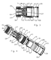
- Figures 1-4 Exemplary embodiments of coaxial connectors configured for connection to annular corrugated solid outer conductor coaxial cable are shown in Figures 1-4 .
- Figures 1 and 2 demonstrate a connector configured for the 7-16 DIN Female standard connection interface
- Figures 3 and 4 demonstrate a connector configured for the 7-16 DIN Male standard connection interface.
- any desired standard or proprietary connection interface may be applied.
- alternative cable attachment mechanisms well known in the art, for example suitable for straight wall or helically corrugated outer conductor coaxial cable, may be applied.
- the connector is configured for use with annular corrugated outer conductor coaxial cable (not shown).
- the cable is received through a bore 1 of a coupling body 3, a slip ring 5 and the connector body 7.
- a leading edge of the outer conductor is retained clamped between an annular ramp surface 9 formed on an end face 10 of an inner body 17 of the connector body 7 and a clamp spring 11, such as a canted coil spring.
- the clamp spring 11 is pressed against the outer surface of the leading edge by the slip ring 5 driven by the coupling body 3.
- the slip ring 5 is rotatable independent of the coupling body 3, to minimize the chance for damage to the clamp spring 11 during rotation of the coupling body 3 to thread the coupling body 3 upon the connector body 7, thus applying the clamping force to the leading edge of the outer conductor.
- An inner conductor of the coaxial cable is received into an inner contact 13 held coaxial within the bore 1 by a dielectric insulator 15.
- a metal inner body 17 is provided as an outer conductor conductive path between the annular ramp surface 9 and the connection interface 19.
- a polymeric outer body 21 surrounds the inner body 17 and may include, for example, tool flats 23 for use during connector assembly and or mating threads 25 for the coupling body 3.
- the slip ring 5 spring mating surface 27 with the clamp spring 11 may be formed of metal, to avoid polymeric material creep that may occur over time which could prevent easy separation of the clamp spring 11 from the split ring 5 when removed, for example, for periodic inspections of the cable and connector interconnection.
- a cylindrical slip ring body 29 that maintains coaxial alignment of the slip ring 5 with the coaxial cable may be formed from polymeric material.
- the coupling body 3 may be formed entirely from polymeric material.
- Environmental sealing of the connector may be improved by applying environmental seal(s) 31 such as gasket(s) and/or o-rings between the outer conductor and the connector, for example positioned between the slip ring 5 and the coupling body 3 and/or between the connector body 7 and the coupling body 3.
- a further sheath seal 33, sealing between the coupling body 3 and an outer sheath of the cable may be formed in place upon an outer surface of the coupling body 3 bore 1, for example molded into an annular groove 35.
- the inner contact 13 may be similarly manufactured by molding, a conventionally machined inner contact 13 is preferred to enable use of beryllium copper and or phosphor bronze alloys with suitable mechanical characteristics for spring finger and/or spring basket 37 features of the inner contact 13 that receive and retain the inner conductor of the cable and/or of the inner conductor mating portions of the mating connector at the connection interface 19.
- multi-shot injection molding is understood to be an injection molding manufacturing procedure wherein additional layers are injection molded upon a base element and/or prior injection molded layers.
- the portion undergoing molding need not be fully released from the mold. Instead, the portion is retained aligned within the mold nest and only portions of the mold as required to define a further cavity to be injection molded with material are reconfigured.
- the resulting element is permanently integrated without any mechanical coupling mechanisms, fasteners or assembly requirements.
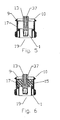
- a mold for the conductive sleeve is injected with the injection moldable metal composition, forming the inner body 17 conductive sleeve.
- An inner portion of the mold is removed and the inner contact 13 positioned therein as shown for example in Figure 5 .
- the inner contact 13 may be positioned first, and mold portions nested thereupon using the inner contact 13 as an alignment element for the various molding operations.
- a space between the inner contact 13 and the inner body 17 is then injected with a dielectric polymer to form the dielectric insulator 15 in situ as shown in Figure 6 .
- the inner body 17 is also positioned as the core for a molding step wherein a polymer is injected to form the outer body 21 in situ as shown in Figure 7 .
- the order of molding is preferably arranged based upon the melting point of the various materials applied with the injection moldable metal composition typically being first, the dielectric polymer second and the outer body 21 polymer last.
- the slip ring mating surface 27, as shown in Figure 8 may be similarly formed by injecting the injection moldable metal composition into a slip ring mating surface mold, then, if desired, replacing a portion of the mold to form an adjacent cavity for injection of polymeric material to form the slip ring body 29 integral with the slip ring mating surface 27 as shown in Figure 9 .
- the coupling body 3, as shown in Figure 10 may be formed by injecting a polymer into a coupling body mold. If desired, the coupling body mold may be opened and portions exchanged to form a sheath seal cavity that is then injected with a polymeric gasket material to form the sheath seal 33 in situ, as shown in Figure 11 .
- the connector is formed in only three main elements that are easily assembled with the desired environmental seal(s) 31, clamp spring 11 and any further connection interface 19 portions to form the connector.
- the slip ring 5 may be eliminated by forming the coupling body 3 as a monolithic polymer portion with a clamp ring surface 39 for direct engagement with the clamp spring 11 or the like, as shown for example in Figures 12-14 .
- FIG. 15 and 16 additional alternative configurations also eliminate the clamp spring 11 by forming the coupling body 3 with spring finger(s) 41.
- a representative coupling body and associated connector body 7 retaining lip 43 are disclosed in detail in US patent application No. 11/672,631 , "Annular Corrugated Coaxial Cable Connector with Polymeric Spring Finger Nut” by Jim Wlos, filed February 8, 2007, co-owned with the present application by Commscope, Inc. of North Carolina and hereby incorporated by reference in the entirety.
- the resulting connector has only two primary elements.
- a spring finger portion 45 may be first formed from the injection moldable metal composition as shown in Figure 17 , over which the remainder of the coupling body 3 is molded from polymer material, as shown in Figure 18 .
- Environmental seal(s) 31, for example between the coupling body 3 and the cable outer conductor and or sheath may also be added, as described herein above.
- the invention provides a significant materials cost and weight savings.
- metal machining By replacing metal machining with injection molding technology, the number of separate sub-elements is significantly reduced, manufacturing is simplified, numerous assembly steps are eliminated and the required skill level(s) of manufacturing personnel are each significantly reduced. Further, because numerous prior elements are multi-shot injection molded directly upon one another, the number of pathways between discrete components is reduced, resulting in a connector with superior long term sealing characteristics requiring fewer environmental seals.
Landscapes
- Engineering & Computer Science (AREA)
- Manufacturing & Machinery (AREA)
- Mechanical Engineering (AREA)
- Coupling Device And Connection With Printed Circuit (AREA)
- Details Of Connecting Devices For Male And Female Coupling (AREA)
- Manufacturing Of Electrical Connectors (AREA)
- Connector Housings Or Holding Contact Members (AREA)
- Injection Moulding Of Plastics Or The Like (AREA)
Claims (20)
- Ein Koaxialkabel-Stecker, umfassend:einen Steckerkörper (7), wobei der Steckerkörper umfasst:einen dielektrischen Isolator (15) aus dielektrischem Polymer, welcher auf einen Außendurchmesser des Innenkontaktes geformt ist;einen koaxialen Innenkörper (17); undeinen Außenkörper (21); dadurch gekennzeichnet, dass der koaxiale Innenkörper (17) aus durch Spritzguss formbarer Metallverbindung hergestellt ist, welche auf einen Außendurchmesser des dielektrischen Isolators (15) geformt ist; undder Außenkörper (21) aus einem Polymer hergestellt ist, welches auf einen Außendurchmesser des Innenkörpers (17) durch Spritzguss geformt ist.
- Koaxialkabel-Stecker gemäß Anspruch 1, welcher ferner einen mit dem Außenkörper (21) schraubbar verbundenen Verbindungskörper (3) aus Polymer aufweist.
- Koaxialkabel Stecker gemäß Anspruch 1, welcher ferner aufweist:eine ringförmige Rampenfläche (9), welche an eine Stirnseite (10) des Innenkörpers (17) angeformt ist,einen im wesentlichen zylindrischen Schleifring (5), welcher innerhalb einer Bohrung (1) des Steckerkörpers (7) positioniert ist,eine Klemmfeder (11), welche zwischen der ringförmigen Rampenfläche (9) und dem Schleifring (5) positioniert ist undeinen Verbindungskörper (3) aus Polymer, welcher mit dem Außenkörper (21) schraubbar verbunden ist und bewirkt, dass der Schleifring gegen die Klemmfeder gedrückt wird.
- Koaxialstecker gemäß Anspruch 1, welcher ferner aufweist:eine ringförmige Rampenfläche (9), welche an eine Stirnseite (10) des Innenkörpers (17) angeformt ist,eine Klemmfeder (11), welche zwischen der ringförmigen Rampenfläche (9) undeinen schraubbar mit dem Außenkörper verbundenen Verbindungskörper (3) aus Polymer angeordnet ist, was bewirkt, dass die Klemmfeder (11) gegen die ringförmige Rampenfläche (9) gedrückt wird.
- Koaxialstecker gemäß Anspruch 1, welcher ferner aufweist:eine ringförmige Rampenfläche (9) an einer Stirnseite (10) des Innenkörpers (17),eine Haltelippe (43) an einer Seitenwand des Innendurchmessers des Außenkörpers (21) nahe der ringförmigen Rampenfläche (9); undeinen Verbindungskörper (3) aus Polymer, welcher schraubbar mit dem Außenkörper (21) verbunden ist;wobei der Verbindungskörper (3) aus Polymer auf ein Federfingerelement (45) aus durch Spritzguss formbarer Metallverbindung geformt ist; wobei mehrere Federfinger (41) des Federfingerelements (45) zu der ringförmigen Rampenfläche (9) vorstehen; wobei das Einschrauben des Verbindungskörpers (3) aus Polymer in den Steckerkörper (7) bewirkt, dass ein distales Ende der Federfinger (41) auf die ringförmige Rampenfläche (9) gedrückt wird.
- Koaxialstecker gemäß Anspruch 1, wobei die durch Spritzguss formbare Metallverbindung eine Legierung ist, die Zink und Aluminium beinhaltet.
- Verfahren zur Herstellung eines Koaxialkabel-Steckers durch Multishot-Spritzgießen, welches die Schritte umfasst:Spritzgießen eines Innenkörpers (17) aus durch Spritzguss formbarer Metallverbindung;Anordnen eines Innenkontaktes (13) innerhalb einer Bohrung (1) des Innenkörpers (17),Spritzgießen eines dielektrischen Isolators (15) zwischen den Innenkörper (17) und den Innenkontakt (13); undSpritzgießen eines Außenkörpers (21) aus Polymer auf eine Fläche des Außendurchmessers des Innenkörpers (17).
- Verfahren gemäß Anspruch 7, welches ferner das Spritzgießen eines Schleifringes (5) umfasst, umfassend:Formen einer Feder-Passfläche (27) des Schleifrings (5) aus durch Spritzguss formbarer Metallverbindung;Spritzgießen eines Schleifringkörpers (29) aus Polymer auf die Feder-Passfläche (27) des Schleifrings (5);Spritzgießen eines Verbindungskörpers (3) und Koppeln des Verbindungskörpers (3) an den Außenkörper (21) durch Verschrauben, wobei der Schleifring (5) zwischen dem Innenkörper (17) und dem Verbindungskörper (3) fixiert wird.
- Verfahren gemäß Anspruch 7, welches ferner das Spritzgießen eines Verbindungskörpers (3) aus Polymer umfasst und
Koppeln des Verbindungskörpers (3) an den Außenkörper (21) durch Verschrauben. - Verfahren gemäß Anspruch 7, wobei ein Federfingerelement (45) des Verbindungskörpers (3) durch Spritzgießen aus einer durch Spritzguss formbaren Metallverbindung geformt wird, und wobei das Verfahren ferner das Spritzgießen eines Polymers um das Federfinger-Element (45) umfasst.
- Verfahren gemäß Anspruch 7, das ferner das Spritzgießen eines Verbindungskörpers (3) umfasst, welcher mit einer Klemmringfläche (39) ausgestattet ist und wobei
eine ringförmige Rampenfläche (9) an einer Stirnseite (10) des Innenkörpers (17) angeformt wird, und der Verbindungskörper (3) in den Außenkörper (21) einschraubbar geformt ist, um die Klemmringfläche (39) gegen die ringförmige Rampenfläche (9) zu drücken. - Verfahren gemäß Anspruch 7, wobei die Metallverbindung für das Spritzgießen eine Legierung ist, die Aluminium und Zink beinhaltet.
- Verfahren gemäß Anspruch 7, wobei das Spritzgießen bei einer Temperatur von 1100 Grad Fahrenheit oder weniger durchgeführt wird.
- Verfahren zur Herstellung eines Koaxialkabel-Steckers durch Multishot-Spritzgießen, welches die Schritte umfasst:Einsetzen eines Innenkontaktes (13) in eine Form;Spritzgießen eines Innenkörpers (17) aus durch Spritzguss formbarer Metallverbindung;Spritzgießen eines dielektrischen Isolators (15) zwischen dem Innenkontakt (13) und dem Innenkörper (17);Spritzgießen eines Außenkörpers (21) aus Polymer auf eine Fläche des Außendurchmessers des Innenkörpers (17).
- Verfahren gemäß Anspruch 14, das ferner das Spritzgießen eines Schleifringes umfasst, umfassend:Formen einer Feder-Passfläche (27) des Schleifringes (5) aus einer durch Spritzguss formbarer Metallverbindung;Spritzgiessen eines Polymer-Schleifringkörpers (29) auf die Feder-Passfläche (27) des Schleifringes (5);Spritzgiessen eines Verbindungskörpers (3) undEinschrauben des Verbindungskörpers (3) in den Steckerkörper (7), Fixieren des Schleifringes (5) zwischen dem Verbindungskörper (3) und dem Steckerkörper (7).
- Verfahren gemäß Anspruch 14, welches ferner das Spritzgießen eines Verbindungskörpers (3) aus Polymer und
das Verschrauben des Verbindungskörpers (3) mit dem Außenkörper (21) umfasst. - Verfahren gemäß Anspruch 16, wobei ein Federfingerelement (45) des Verbindungskörpers (3) durch Spritzgießen aus einer durch Spritzguss formbaren Metallverbindung hergestellt wird, und das Verfahren ferner das Spritzgießen eines Polymers um das Federfinger Element (45) umfasst.
- Verfahren gemäß Anspruch 14, welches ferner das Spritzgießen eines Verbindungskörpers (3) umfasst, welcher eine Klemmringfläche (39) aufweist, und
wobei eine ringförmige Rampenfläche (9) an eine Stirnseite (10) des Innenkörpers (17) angeformt wird;
wobei der Verbindungskörper (3) in den Außenkörper (21) einschraubbar geformt wird, um die Klemmringfläche (39) gegen die ringförmige Rampenfläche (9) zu drücken. - Verfahren gemäß Anspruch 14, wobei die Metallverbindung für das Spritzgießen eine Legierung ist, die Aluminium und Zink beinhaltet.
- Verfahren gemäß Anspruch 14, wobei das Spritzgießen bei einer Temperatur von 1100 Grad Fahrenheit oder weniger durchgeführt wird.
Applications Claiming Priority (1)
| Application Number | Priority Date | Filing Date | Title |
|---|---|---|---|
| US12/191,922 US7607942B1 (en) | 2008-08-14 | 2008-08-14 | Multi-shot coaxial connector and method of manufacture |
Publications (2)
| Publication Number | Publication Date |
|---|---|
| EP2154754A1 EP2154754A1 (de) | 2010-02-17 |
| EP2154754B1 true EP2154754B1 (de) | 2011-09-07 |
Family
ID=41161319
Family Applications (1)
| Application Number | Title | Priority Date | Filing Date |
|---|---|---|---|
| EP09009691A Not-in-force EP2154754B1 (de) | 2008-08-14 | 2009-07-27 | Multishot-Koaxialstecker und Herstellungsverfahren |
Country Status (5)
| Country | Link |
|---|---|
| US (1) | US7607942B1 (de) |
| EP (1) | EP2154754B1 (de) |
| JP (1) | JP2010045031A (de) |
| CN (1) | CN101651276A (de) |
| AT (1) | ATE523927T1 (de) |
Families Citing this family (94)
| Publication number | Priority date | Publication date | Assignee | Title |
|---|---|---|---|---|
| US8157589B2 (en) | 2004-11-24 | 2012-04-17 | John Mezzalingua Associates, Inc. | Connector having a conductively coated member and method of use thereof |
| US7114990B2 (en) | 2005-01-25 | 2006-10-03 | Corning Gilbert Incorporated | Coaxial cable connector with grounding member |
| US20110003507A1 (en) * | 2008-08-14 | 2011-01-06 | Andrew Llc | Multi-shot Connector Assembly and Method of Manufacture |
| US7837502B2 (en) * | 2008-08-14 | 2010-11-23 | Andrew Llc | Multi-shot coaxial connector and method of manufacture |
| US8062063B2 (en) | 2008-09-30 | 2011-11-22 | Belden Inc. | Cable connector having a biasing element |
| GB2466255B (en) * | 2008-12-17 | 2013-05-22 | Antenova Ltd | Antennas conducive to semiconductor packaging technology and a process for their manufacture |
| US8047870B2 (en) * | 2009-01-09 | 2011-11-01 | Corning Gilbert Inc. | Coaxial connector for corrugated cable |
| US8025518B2 (en) | 2009-02-24 | 2011-09-27 | Corning Gilbert Inc. | Coaxial connector with dual-grip nut |
| US8029315B2 (en) * | 2009-04-01 | 2011-10-04 | John Mezzalingua Associates, Inc. | Coaxial cable connector with improved physical and RF sealing |
| US7824216B2 (en) | 2009-04-02 | 2010-11-02 | John Mezzalingua Associates, Inc. | Coaxial cable continuity connector |
| US8573996B2 (en) | 2009-05-22 | 2013-11-05 | Ppc Broadband, Inc. | Coaxial cable connector having electrical continuity member |
| US9570845B2 (en) | 2009-05-22 | 2017-02-14 | Ppc Broadband, Inc. | Connector having a continuity member operable in a radial direction |
| US8444445B2 (en) | 2009-05-22 | 2013-05-21 | Ppc Broadband, Inc. | Coaxial cable connector having electrical continuity member |
| US9017101B2 (en) | 2011-03-30 | 2015-04-28 | Ppc Broadband, Inc. | Continuity maintaining biasing member |
| US8287320B2 (en) | 2009-05-22 | 2012-10-16 | John Mezzalingua Associates, Inc. | Coaxial cable connector having electrical continuity member |
| BRPI1015143A2 (pt) * | 2009-06-05 | 2016-10-25 | Andrew Llc | conector coaxial de contato de anel deslizante. |
| US8517763B2 (en) * | 2009-11-06 | 2013-08-27 | Corning Gilbert Inc. | Integrally conductive locking coaxial connector |
| US8272893B2 (en) | 2009-11-16 | 2012-09-25 | Corning Gilbert Inc. | Integrally conductive and shielded coaxial cable connector |
| WO2011107075A2 (de) * | 2010-03-01 | 2011-09-09 | Franz Binder Gmbh + Co. Elektrische Bauelemente Kg | Verfahren zum herstellen einer elektrischen schnittstelle und schnittstelle |
| TWI549386B (zh) | 2010-04-13 | 2016-09-11 | 康寧吉伯特公司 | 具有防止進入及改良接地之同軸連接器 |
| US8152551B2 (en) | 2010-07-22 | 2012-04-10 | John Mezzalingua Associates, Inc. | Port seizing cable connector nut and assembly |
| US8079860B1 (en) | 2010-07-22 | 2011-12-20 | John Mezzalingua Associates, Inc. | Cable connector having threaded locking collet and nut |
| US8113879B1 (en) | 2010-07-27 | 2012-02-14 | John Mezzalingua Associates, Inc. | One-piece compression connector body for coaxial cable connector |
| US8888526B2 (en) | 2010-08-10 | 2014-11-18 | Corning Gilbert, Inc. | Coaxial cable connector with radio frequency interference and grounding shield |
| DE102010037193A1 (de) * | 2010-08-27 | 2012-03-01 | Phoenix Contact Gmbh & Co. Kg | Kabelzugentlastung |
| US8167636B1 (en) | 2010-10-15 | 2012-05-01 | John Mezzalingua Associates, Inc. | Connector having a continuity member |
| US8323053B2 (en) | 2010-10-18 | 2012-12-04 | John Mezzalingua Associates, Inc. | Connector having a constant contact nut |
| US8075338B1 (en) | 2010-10-18 | 2011-12-13 | John Mezzalingua Associates, Inc. | Connector having a constant contact post |
| US8167646B1 (en) | 2010-10-18 | 2012-05-01 | John Mezzalingua Associates, Inc. | Connector having electrical continuity about an inner dielectric and method of use thereof |
| US8167635B1 (en) | 2010-10-18 | 2012-05-01 | John Mezzalingua Associates, Inc. | Dielectric sealing member and method of use thereof |
| TWI558022B (zh) | 2010-10-27 | 2016-11-11 | 康寧吉伯特公司 | 具有耦合器和固持及釋放機制的推入固定式纜線連接器 |
| US8337229B2 (en) | 2010-11-11 | 2012-12-25 | John Mezzalingua Associates, Inc. | Connector having a nut-body continuity element and method of use thereof |
| US8479383B2 (en) | 2010-11-22 | 2013-07-09 | Andrew Llc | Friction weld coaxial connector and interconnection method |
| US9761959B2 (en) | 2010-11-22 | 2017-09-12 | Commscope Technologies Llc | Ultrasonic weld coaxial connector |
| US8887388B2 (en) | 2010-11-22 | 2014-11-18 | Andrew Llc | Method for interconnecting a coaxial connector with a solid outer conductor coaxial cable |
| US8622768B2 (en) | 2010-11-22 | 2014-01-07 | Andrew Llc | Connector with capacitively coupled connector interface |
| US8302296B2 (en) | 2010-11-22 | 2012-11-06 | Andrew, Llc | Friction weld coaxial connector and interconnection method |
| US8365404B2 (en) | 2010-11-22 | 2013-02-05 | Andrew Llc | Method for ultrasonic welding a coaxial cable to a coaxial connector |
| US8563861B2 (en) | 2010-11-22 | 2013-10-22 | Andrew Llc | Friction weld inner conductor cap and interconnection method |
| US8453320B2 (en) | 2010-11-22 | 2013-06-04 | Andrew Llc | Method of interconnecting a coaxial connector to a coaxial cable via ultrasonic welding |
| US8826525B2 (en) | 2010-11-22 | 2014-09-09 | Andrew Llc | Laser weld coaxial connector and interconnection method |
| US8876549B2 (en) | 2010-11-22 | 2014-11-04 | Andrew Llc | Capacitively coupled flat conductor connector |
| US9728926B2 (en) | 2010-11-22 | 2017-08-08 | Commscope Technologies Llc | Method and apparatus for radial ultrasonic welding interconnected coaxial connector |
| US8414322B2 (en) | 2010-12-14 | 2013-04-09 | Ppc Broadband, Inc. | Push-on CATV port terminator |
| US8398421B2 (en) | 2011-02-01 | 2013-03-19 | John Mezzalingua Associates, Inc. | Connector having a dielectric seal and method of use thereof |
| US8157588B1 (en) | 2011-02-08 | 2012-04-17 | Belden Inc. | Cable connector with biasing element |
| US9062386B2 (en) | 2011-03-01 | 2015-06-23 | Srg Global, Inc. | Methods of multi-shot injection molding and metal-plated polymeric articles made therefrom |
| US8465322B2 (en) | 2011-03-25 | 2013-06-18 | Ppc Broadband, Inc. | Coaxial cable connector |
| US8342879B2 (en) | 2011-03-25 | 2013-01-01 | John Mezzalingua Associates, Inc. | Coaxial cable connector |
| US8366481B2 (en) | 2011-03-30 | 2013-02-05 | John Mezzalingua Associates, Inc. | Continuity maintaining biasing member |
| US8388377B2 (en) | 2011-04-01 | 2013-03-05 | John Mezzalingua Associates, Inc. | Slide actuated coaxial cable connector |
| US8348697B2 (en) | 2011-04-22 | 2013-01-08 | John Mezzalingua Associates, Inc. | Coaxial cable connector having slotted post member |
| US9711917B2 (en) | 2011-05-26 | 2017-07-18 | Ppc Broadband, Inc. | Band spring continuity member for coaxial cable connector |
| US9203167B2 (en) | 2011-05-26 | 2015-12-01 | Ppc Broadband, Inc. | Coaxial cable connector with conductive seal |
| US8758050B2 (en) | 2011-06-10 | 2014-06-24 | Hiscock & Barclay LLP | Connector having a coupling member for locking onto a port and maintaining electrical continuity |
| US8591244B2 (en) | 2011-07-08 | 2013-11-26 | Ppc Broadband, Inc. | Cable connector |
| US9190744B2 (en) | 2011-09-14 | 2015-11-17 | Corning Optical Communications Rf Llc | Coaxial cable connector with radio frequency interference and grounding shield |
| US20130072057A1 (en) | 2011-09-15 | 2013-03-21 | Donald Andrew Burris | Coaxial cable connector with integral radio frequency interference and grounding shield |
| US9147955B2 (en) | 2011-11-02 | 2015-09-29 | Ppc Broadband, Inc. | Continuity providing port |
| WO2013071204A1 (en) * | 2011-11-11 | 2013-05-16 | Andrew Llc | Connector with capacitively coupled connector interface |
| US8558746B2 (en) | 2011-11-16 | 2013-10-15 | Andrew Llc | Flat panel array antenna |
| US8866687B2 (en) | 2011-11-16 | 2014-10-21 | Andrew Llc | Modular feed network |
| US9160049B2 (en) | 2011-11-16 | 2015-10-13 | Commscope Technologies Llc | Antenna adapter |
| US9136654B2 (en) | 2012-01-05 | 2015-09-15 | Corning Gilbert, Inc. | Quick mount connector for a coaxial cable |
| EP2615699B1 (de) * | 2012-01-11 | 2017-03-22 | Spinner GmbH | HF-Verbinder |
| US9407016B2 (en) | 2012-02-22 | 2016-08-02 | Corning Optical Communications Rf Llc | Coaxial cable connector with integral continuity contacting portion |
| JP5680005B2 (ja) * | 2012-02-24 | 2015-03-04 | 株式会社東芝 | コネクタの嵌合状態を検査する検査方法および検査装置、並びにコネクタを有する電気機器の組立方法 |
| CN102623829A (zh) * | 2012-03-09 | 2012-08-01 | 深圳市大富科技股份有限公司 | 一种腔体滤波器、连接器及相应的制造工艺 |
| US8777658B2 (en) * | 2012-03-19 | 2014-07-15 | Holland Electronics, Llc | Ingress reduction coaxial cable connector |
| US9793660B2 (en) * | 2012-03-19 | 2017-10-17 | Holland Electronics, Llc | Shielded coaxial connector |
| EP2680372B1 (de) * | 2012-06-29 | 2017-06-07 | Corning Optical Communications RF LLC | Isolator mit mehreren Abschnitten für Koaxialstecker |
| US9287659B2 (en) | 2012-10-16 | 2016-03-15 | Corning Optical Communications Rf Llc | Coaxial cable connector with integral RFI protection |
| US9048527B2 (en) | 2012-11-09 | 2015-06-02 | Commscope Technologies Llc | Coaxial connector with capacitively coupled connector interface and method of manufacture |
| US9147963B2 (en) | 2012-11-29 | 2015-09-29 | Corning Gilbert Inc. | Hardline coaxial connector with a locking ferrule |
| US9153911B2 (en) | 2013-02-19 | 2015-10-06 | Corning Gilbert Inc. | Coaxial cable continuity connector |
| US9172154B2 (en) | 2013-03-15 | 2015-10-27 | Corning Gilbert Inc. | Coaxial cable connector with integral RFI protection |
| US9130281B2 (en) | 2013-04-17 | 2015-09-08 | Ppc Broadband, Inc. | Post assembly for coaxial cable connectors |
| US10290958B2 (en) | 2013-04-29 | 2019-05-14 | Corning Optical Communications Rf Llc | Coaxial cable connector with integral RFI protection and biasing ring |
| CN105284015B (zh) | 2013-05-20 | 2019-03-08 | 康宁光电通信Rf有限责任公司 | 具有整体rfi保护的同轴电缆连接器 |
| US9548557B2 (en) | 2013-06-26 | 2017-01-17 | Corning Optical Communications LLC | Connector assemblies and methods of manufacture |
| US9048599B2 (en) | 2013-10-28 | 2015-06-02 | Corning Gilbert Inc. | Coaxial cable connector having a gripping member with a notch and disposed inside a shell |
| US20160126664A1 (en) * | 2014-10-31 | 2016-05-05 | Motorola Solutions, Inc | Connector providing combined fastener and radio frequency interface |
| US9548572B2 (en) | 2014-11-03 | 2017-01-17 | Corning Optical Communications LLC | Coaxial cable connector having a coupler and a post with a contacting portion and a shoulder |
| US10033122B2 (en) | 2015-02-20 | 2018-07-24 | Corning Optical Communications Rf Llc | Cable or conduit connector with jacket retention feature |
| US9590287B2 (en) | 2015-02-20 | 2017-03-07 | Corning Optical Communications Rf Llc | Surge protected coaxial termination |
| US10211547B2 (en) | 2015-09-03 | 2019-02-19 | Corning Optical Communications Rf Llc | Coaxial cable connector |
| US9525220B1 (en) | 2015-11-25 | 2016-12-20 | Corning Optical Communications LLC | Coaxial cable connector |
| CN108963687A (zh) * | 2018-07-11 | 2018-12-07 | 嘉兴市金利达电子有限公司 | 一种加强型音频线接头 |
| USD913945S1 (en) * | 2018-08-01 | 2021-03-23 | Gigalane Co., Ltd. | Connector for signal transmission |
| CN112787182A (zh) * | 2019-11-05 | 2021-05-11 | 康普技术有限责任公司 | 电缆连通器和电缆组件 |
| CA3183218A1 (en) * | 2020-06-19 | 2021-12-23 | Donald Andrew Burris | Coaxial blindmate connectors and methods for using the same |
| CN112895337B (zh) * | 2021-03-29 | 2022-08-12 | 深圳市创益通技术股份有限公司 | Smp母座自动化生产注塑模具结构 |
| US12034264B2 (en) | 2021-03-31 | 2024-07-09 | Corning Optical Communications Rf Llc | Coaxial cable connector assemblies with outer conductor engagement features and methods for using the same |
| US12482970B2 (en) | 2021-10-19 | 2025-11-25 | Corning Optical Communications Rf Llc | Bullet-type connectors, printed circuit board assemblies, and methods |
Family Cites Families (15)
| Publication number | Priority date | Publication date | Assignee | Title |
|---|---|---|---|---|
| US5137470A (en) * | 1991-06-04 | 1992-08-11 | Andrew Corporation | Connector for coaxial cable having a helically corrugated inner conductor |
| US5354217A (en) | 1993-06-10 | 1994-10-11 | Andrew Corporation | Lightweight connector for a coaxial cable |
| DE10350763A1 (de) * | 2002-11-16 | 2004-06-03 | Spinner Gmbh Elektrotechnische Fabrik | Koaxialkabel mit Winkelsteckverbindung |
| US7249969B2 (en) * | 2003-07-28 | 2007-07-31 | Andrew Corporation | Connector with corrugated cable interface insert |
| US7029304B2 (en) * | 2004-02-04 | 2006-04-18 | John Mezzalingua Associates, Inc. | Compression connector with integral coupler |
| CN100559515C (zh) * | 2004-11-04 | 2009-11-11 | 中国电子科技集团公司第四十一研究所 | 一种适用于宽温度范围的高性能同轴连接器介质支撑 |
| JP2007042415A (ja) * | 2005-08-03 | 2007-02-15 | D D K Ltd | 同軸コネクタ |
| US7217154B2 (en) * | 2005-10-19 | 2007-05-15 | Andrew Corporation | Connector with outer conductor axial compression connection and method of manufacture |
| US7517258B1 (en) * | 2006-01-31 | 2009-04-14 | H-Tech, Llc | Hermetically sealed coaxial type feed-through RF Connector |
| CN1835299A (zh) * | 2006-03-01 | 2006-09-20 | 四川华丰企业集团有限公司 | 一种射频同轴连接器 |
| US7275957B1 (en) * | 2006-03-22 | 2007-10-02 | Andrew Corporation | Axial compression electrical connector for annular corrugated coaxial cable |
| US8174132B2 (en) * | 2007-01-17 | 2012-05-08 | Andrew Llc | Folded surface capacitor in-line assembly |
| US7435135B2 (en) | 2007-02-08 | 2008-10-14 | Andrew Corporation | Annular corrugated coaxial cable connector with polymeric spring finger nut |
| FR2915324B1 (fr) * | 2007-04-17 | 2009-07-03 | Radiall Sa | Embase de connexion coaxiale 7-16. |
| US7419403B1 (en) * | 2007-06-20 | 2008-09-02 | Commscope, Inc. Of North Carolina | Angled coaxial connector with inner conductor transition and method of manufacture |
-
2008
- 2008-08-14 US US12/191,922 patent/US7607942B1/en active Active
-
2009
- 2009-07-27 AT AT09009691T patent/ATE523927T1/de not_active IP Right Cessation
- 2009-07-27 EP EP09009691A patent/EP2154754B1/de not_active Not-in-force
- 2009-08-11 JP JP2009186916A patent/JP2010045031A/ja active Pending
- 2009-08-14 CN CN200910162627A patent/CN101651276A/zh active Pending
Also Published As
| Publication number | Publication date |
|---|---|
| ATE523927T1 (de) | 2011-09-15 |
| US7607942B1 (en) | 2009-10-27 |
| EP2154754A1 (de) | 2010-02-17 |
| JP2010045031A (ja) | 2010-02-25 |
| CN101651276A (zh) | 2010-02-17 |
Similar Documents
| Publication | Publication Date | Title |
|---|---|---|
| EP2154754B1 (de) | Multishot-Koaxialstecker und Herstellungsverfahren | |
| US7837502B2 (en) | Multi-shot coaxial connector and method of manufacture | |
| EP2432081A1 (de) | Multishot-Steckeranordnung und Herstellungsverfahren | |
| EP2184814B1 (de) | Koaxialer Axialkompressionssteckverbinder | |
| US7661984B2 (en) | Locking threaded connection coaxial connector | |
| KR101044271B1 (ko) | 동축 케이블용 압축 커넥터 | |
| EP1777784B1 (de) | Stecker mit axialer Anschlußkompression des äußeren Leiters und Herstellungmethode | |
| US6939169B2 (en) | Axial compression electrical connector | |
| US7753727B1 (en) | Threaded crimp coaxial connector | |
| EP2009746B1 (de) | Koaxialer Winkelstecker mit innerem Leitungsübergang und Herstellungsverfahren | |
| CN100433459C (zh) | 与具有内外导体和外皮的同轴电缆配合使用的同轴连接器 | |
| US6994587B2 (en) | Coaxial cable connector installable with common tools | |
| EP1837952A2 (de) | Elektrischer Verbinder mit axialer Kompression für ein ringförmiges, geriffeltes Koaxialkabel | |
| EP1956687A2 (de) | Verbinder für ein ringförmiges, geriffeltes Koaxialkabel mit polymerer Flügelfedermutter | |
| WO2011053439A2 (en) | Self gauging insertion coupling coaxial connector | |
| US20120184135A1 (en) | Low PIM Coaxial Connector | |
| EP2497157A2 (de) | Selbstkalibrierender koaxialsteckverbinder mit einsatzkupplung | |
| EP2083484A2 (de) | Koaxialstecker mit Sperrgewindeverbindung | |
| CN100574017C (zh) | 电连接装置 | |
| CN117406347A (zh) | 室外防水快速连接器 | |
| HK1150682A (en) | Compression connector for coaxial cable |
Legal Events
| Date | Code | Title | Description |
|---|---|---|---|
| PUAI | Public reference made under article 153(3) epc to a published international application that has entered the european phase |
Free format text: ORIGINAL CODE: 0009012 |
|
| AK | Designated contracting states |
Kind code of ref document: A1 Designated state(s): AT BE BG CH CY CZ DE DK EE ES FI FR GB GR HR HU IE IS IT LI LT LU LV MC MK MT NL NO PL PT RO SE SI SK SM TR |
|
| AX | Request for extension of the european patent |
Extension state: AL BA RS |
|
| 17P | Request for examination filed |
Effective date: 20100329 |
|
| 17Q | First examination report despatched |
Effective date: 20100526 |
|
| GRAP | Despatch of communication of intention to grant a patent |
Free format text: ORIGINAL CODE: EPIDOSNIGR1 |
|
| GRAS | Grant fee paid |
Free format text: ORIGINAL CODE: EPIDOSNIGR3 |
|
| GRAA | (expected) grant |
Free format text: ORIGINAL CODE: 0009210 |
|
| REG | Reference to a national code |
Ref country code: GB Ref legal event code: FG4D |
|
| REG | Reference to a national code |
Ref country code: CH Ref legal event code: EP |
|
| REG | Reference to a national code |
Ref country code: IE Ref legal event code: FG4D |
|
| REG | Reference to a national code |
Ref country code: CH Ref legal event code: NV Representative=s name: OFFICE ERNEST T. FREYLINGER S.A. |
|
| REG | Reference to a national code |
Ref country code: DE Ref legal event code: R096 Ref document number: 602009002486 Country of ref document: DE Effective date: 20111117 |
|
| REG | Reference to a national code |
Ref country code: NL Ref legal event code: VDEP Effective date: 20110907 |
|
| PG25 | Lapsed in a contracting state [announced via postgrant information from national office to epo] |
Ref country code: HR Free format text: LAPSE BECAUSE OF FAILURE TO SUBMIT A TRANSLATION OF THE DESCRIPTION OR TO PAY THE FEE WITHIN THE PRESCRIBED TIME-LIMIT Effective date: 20110907 Ref country code: LT Free format text: LAPSE BECAUSE OF FAILURE TO SUBMIT A TRANSLATION OF THE DESCRIPTION OR TO PAY THE FEE WITHIN THE PRESCRIBED TIME-LIMIT Effective date: 20110907 Ref country code: SE Free format text: LAPSE BECAUSE OF FAILURE TO SUBMIT A TRANSLATION OF THE DESCRIPTION OR TO PAY THE FEE WITHIN THE PRESCRIBED TIME-LIMIT Effective date: 20110907 Ref country code: NO Free format text: LAPSE BECAUSE OF FAILURE TO SUBMIT A TRANSLATION OF THE DESCRIPTION OR TO PAY THE FEE WITHIN THE PRESCRIBED TIME-LIMIT Effective date: 20111207 |
|
| LTIE | Lt: invalidation of european patent or patent extension |
Effective date: 20110907 |
|
| PG25 | Lapsed in a contracting state [announced via postgrant information from national office to epo] |
Ref country code: CY Free format text: LAPSE BECAUSE OF FAILURE TO SUBMIT A TRANSLATION OF THE DESCRIPTION OR TO PAY THE FEE WITHIN THE PRESCRIBED TIME-LIMIT Effective date: 20110907 Ref country code: LV Free format text: LAPSE BECAUSE OF FAILURE TO SUBMIT A TRANSLATION OF THE DESCRIPTION OR TO PAY THE FEE WITHIN THE PRESCRIBED TIME-LIMIT Effective date: 20110907 Ref country code: GR Free format text: LAPSE BECAUSE OF FAILURE TO SUBMIT A TRANSLATION OF THE DESCRIPTION OR TO PAY THE FEE WITHIN THE PRESCRIBED TIME-LIMIT Effective date: 20111208 Ref country code: AT Free format text: LAPSE BECAUSE OF FAILURE TO SUBMIT A TRANSLATION OF THE DESCRIPTION OR TO PAY THE FEE WITHIN THE PRESCRIBED TIME-LIMIT Effective date: 20110907 Ref country code: SI Free format text: LAPSE BECAUSE OF FAILURE TO SUBMIT A TRANSLATION OF THE DESCRIPTION OR TO PAY THE FEE WITHIN THE PRESCRIBED TIME-LIMIT Effective date: 20110907 |
|
| REG | Reference to a national code |
Ref country code: AT Ref legal event code: MK05 Ref document number: 523927 Country of ref document: AT Kind code of ref document: T Effective date: 20110907 |
|
| PG25 | Lapsed in a contracting state [announced via postgrant information from national office to epo] |
Ref country code: BE Free format text: LAPSE BECAUSE OF FAILURE TO SUBMIT A TRANSLATION OF THE DESCRIPTION OR TO PAY THE FEE WITHIN THE PRESCRIBED TIME-LIMIT Effective date: 20110907 |
|
| PG25 | Lapsed in a contracting state [announced via postgrant information from national office to epo] |
Ref country code: CZ Free format text: LAPSE BECAUSE OF FAILURE TO SUBMIT A TRANSLATION OF THE DESCRIPTION OR TO PAY THE FEE WITHIN THE PRESCRIBED TIME-LIMIT Effective date: 20110907 Ref country code: SK Free format text: LAPSE BECAUSE OF FAILURE TO SUBMIT A TRANSLATION OF THE DESCRIPTION OR TO PAY THE FEE WITHIN THE PRESCRIBED TIME-LIMIT Effective date: 20110907 Ref country code: IS Free format text: LAPSE BECAUSE OF FAILURE TO SUBMIT A TRANSLATION OF THE DESCRIPTION OR TO PAY THE FEE WITHIN THE PRESCRIBED TIME-LIMIT Effective date: 20120107 |
|
| PG25 | Lapsed in a contracting state [announced via postgrant information from national office to epo] |
Ref country code: PT Free format text: LAPSE BECAUSE OF FAILURE TO SUBMIT A TRANSLATION OF THE DESCRIPTION OR TO PAY THE FEE WITHIN THE PRESCRIBED TIME-LIMIT Effective date: 20120109 Ref country code: EE Free format text: LAPSE BECAUSE OF FAILURE TO SUBMIT A TRANSLATION OF THE DESCRIPTION OR TO PAY THE FEE WITHIN THE PRESCRIBED TIME-LIMIT Effective date: 20110907 Ref country code: RO Free format text: LAPSE BECAUSE OF FAILURE TO SUBMIT A TRANSLATION OF THE DESCRIPTION OR TO PAY THE FEE WITHIN THE PRESCRIBED TIME-LIMIT Effective date: 20110907 Ref country code: PL Free format text: LAPSE BECAUSE OF FAILURE TO SUBMIT A TRANSLATION OF THE DESCRIPTION OR TO PAY THE FEE WITHIN THE PRESCRIBED TIME-LIMIT Effective date: 20110907 Ref country code: NL Free format text: LAPSE BECAUSE OF FAILURE TO SUBMIT A TRANSLATION OF THE DESCRIPTION OR TO PAY THE FEE WITHIN THE PRESCRIBED TIME-LIMIT Effective date: 20110907 |
|
| PLBE | No opposition filed within time limit |
Free format text: ORIGINAL CODE: 0009261 |
|
| STAA | Information on the status of an ep patent application or granted ep patent |
Free format text: STATUS: NO OPPOSITION FILED WITHIN TIME LIMIT |
|
| PG25 | Lapsed in a contracting state [announced via postgrant information from national office to epo] |
Ref country code: DK Free format text: LAPSE BECAUSE OF FAILURE TO SUBMIT A TRANSLATION OF THE DESCRIPTION OR TO PAY THE FEE WITHIN THE PRESCRIBED TIME-LIMIT Effective date: 20110907 |
|
| 26N | No opposition filed |
Effective date: 20120611 |
|
| PGFP | Annual fee paid to national office [announced via postgrant information from national office to epo] |
Ref country code: IT Payment date: 20120630 Year of fee payment: 4 |
|
| REG | Reference to a national code |
Ref country code: DE Ref legal event code: R097 Ref document number: 602009002486 Country of ref document: DE Effective date: 20120611 |
|
| PGFP | Annual fee paid to national office [announced via postgrant information from national office to epo] |
Ref country code: FI Payment date: 20120727 Year of fee payment: 4 |
|
| PGFP | Annual fee paid to national office [announced via postgrant information from national office to epo] |
Ref country code: FR Payment date: 20120731 Year of fee payment: 4 Ref country code: DE Payment date: 20120727 Year of fee payment: 4 |
|
| PG25 | Lapsed in a contracting state [announced via postgrant information from national office to epo] |
Ref country code: MC Free format text: LAPSE BECAUSE OF NON-PAYMENT OF DUE FEES Effective date: 20120731 Ref country code: MK Free format text: LAPSE BECAUSE OF FAILURE TO SUBMIT A TRANSLATION OF THE DESCRIPTION OR TO PAY THE FEE WITHIN THE PRESCRIBED TIME-LIMIT Effective date: 20110907 |
|
| PG25 | Lapsed in a contracting state [announced via postgrant information from national office to epo] |
Ref country code: ES Free format text: LAPSE BECAUSE OF FAILURE TO SUBMIT A TRANSLATION OF THE DESCRIPTION OR TO PAY THE FEE WITHIN THE PRESCRIBED TIME-LIMIT Effective date: 20111218 |
|
| REG | Reference to a national code |
Ref country code: IE Ref legal event code: MM4A |
|
| PG25 | Lapsed in a contracting state [announced via postgrant information from national office to epo] |
Ref country code: BG Free format text: LAPSE BECAUSE OF FAILURE TO SUBMIT A TRANSLATION OF THE DESCRIPTION OR TO PAY THE FEE WITHIN THE PRESCRIBED TIME-LIMIT Effective date: 20111207 |
|
| PG25 | Lapsed in a contracting state [announced via postgrant information from national office to epo] |
Ref country code: IE Free format text: LAPSE BECAUSE OF NON-PAYMENT OF DUE FEES Effective date: 20120727 Ref country code: MT Free format text: LAPSE BECAUSE OF FAILURE TO SUBMIT A TRANSLATION OF THE DESCRIPTION OR TO PAY THE FEE WITHIN THE PRESCRIBED TIME-LIMIT Effective date: 20110907 |
|
| REG | Reference to a national code |
Ref country code: CH Ref legal event code: PL |
|
| GBPC | Gb: european patent ceased through non-payment of renewal fee |
Effective date: 20130727 |
|
| REG | Reference to a national code |
Ref country code: DE Ref legal event code: R119 Ref document number: 602009002486 Country of ref document: DE Effective date: 20140201 |
|
| REG | Reference to a national code |
Ref country code: FR Ref legal event code: ST Effective date: 20140331 |
|
| PG25 | Lapsed in a contracting state [announced via postgrant information from national office to epo] |
Ref country code: TR Free format text: LAPSE BECAUSE OF FAILURE TO SUBMIT A TRANSLATION OF THE DESCRIPTION OR TO PAY THE FEE WITHIN THE PRESCRIBED TIME-LIMIT Effective date: 20110907 Ref country code: CH Free format text: LAPSE BECAUSE OF NON-PAYMENT OF DUE FEES Effective date: 20130731 Ref country code: DE Free format text: LAPSE BECAUSE OF NON-PAYMENT OF DUE FEES Effective date: 20140201 Ref country code: GB Free format text: LAPSE BECAUSE OF NON-PAYMENT OF DUE FEES Effective date: 20130727 Ref country code: FI Free format text: LAPSE BECAUSE OF NON-PAYMENT OF DUE FEES Effective date: 20130727 Ref country code: LI Free format text: LAPSE BECAUSE OF NON-PAYMENT OF DUE FEES Effective date: 20130731 |
|
| PG25 | Lapsed in a contracting state [announced via postgrant information from national office to epo] |
Ref country code: LU Free format text: LAPSE BECAUSE OF NON-PAYMENT OF DUE FEES Effective date: 20120727 Ref country code: FR Free format text: LAPSE BECAUSE OF NON-PAYMENT OF DUE FEES Effective date: 20130731 Ref country code: SM Free format text: LAPSE BECAUSE OF FAILURE TO SUBMIT A TRANSLATION OF THE DESCRIPTION OR TO PAY THE FEE WITHIN THE PRESCRIBED TIME-LIMIT Effective date: 20110907 Ref country code: IT Free format text: LAPSE BECAUSE OF NON-PAYMENT OF DUE FEES Effective date: 20130727 |
|
| PG25 | Lapsed in a contracting state [announced via postgrant information from national office to epo] |
Ref country code: HU Free format text: LAPSE BECAUSE OF FAILURE TO SUBMIT A TRANSLATION OF THE DESCRIPTION OR TO PAY THE FEE WITHIN THE PRESCRIBED TIME-LIMIT Effective date: 20090727 |